Cooling Fans - orientalmotor.com · Cooling Fans Centrifugal Blowers Centrifugal blowers maximize...
23
Cooling Fans Thermostats Axial Flow Fans AC Input DC Input AC Input DC Input DC Input Centrifugal Blowers Cross Flow Fans AC Input MRS Variable Flow MU Long Life MDE MDS MD MB MBD MF MFD Accessories Introduction Before Using a Fan Centrifugal Blowers Introduction································································E-62 MB Series ·································································E-66 MBD Series·······························································E-78 Technical Reference················································F-1 General Information ················································G-1 Additional Information E-61
Transcript of Cooling Fans - orientalmotor.com · Cooling Fans Centrifugal Blowers Centrifugal blowers maximize...
Co
olin
gFan
sTherm
ostats
Axial F
low
Fans
AC
Inp
ut
DC
Inp
ut
AC
Inp
ut
DC
Inp
ut
DC
Inp
ut
Cen
trifug
al Blo
wers
Cross Flow
FansA
C In
pu
t
MRS
Variab
leF
low
MU
Lo
ng
Life
MD
EM
DS M
DM
BM
BD
MF
MFD
AccessoriesIntroduction
Before Usinga Fan
Centrifugal Blowers
Introduction································································E-62MB Series ·································································E-66MBD Series·······························································E-78
Technical Reference················································F-1General Information················································G-1
Additional Information
E-61

E-62
Co
olin
gFan
s
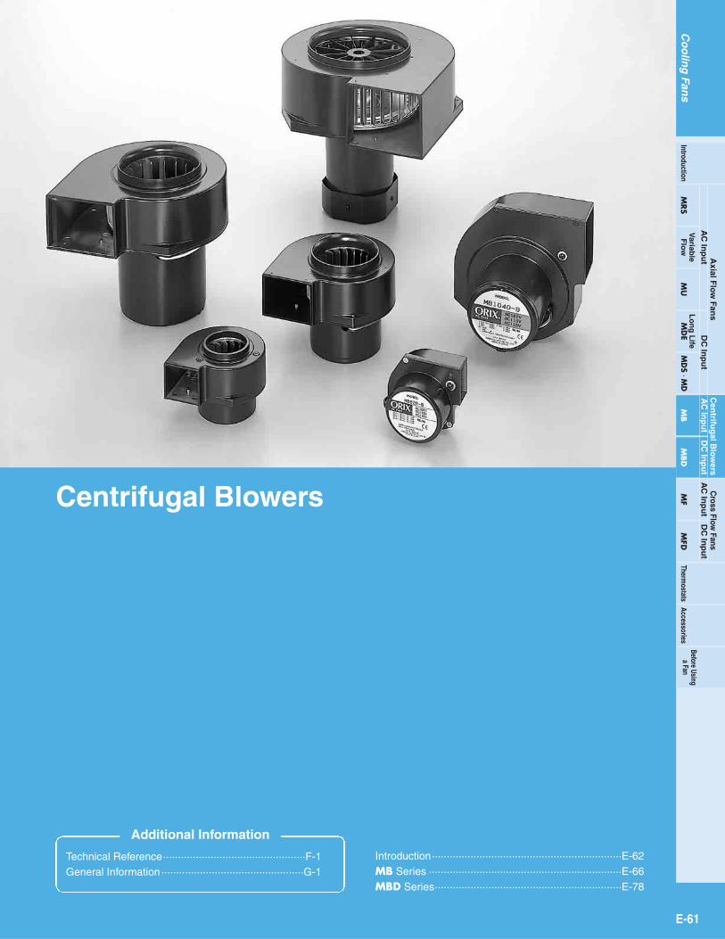
Centrifugal Blowers
Centrifugal blowers maximize static pressure toprovide concentrated airflow in one defined direction.These blowers can be used in a fixed position ormounted on moving parts, and are optimal for localcooling and airflow through ducts.
Safety Standards and CE MarkingModel Standards Certification Body Standards File No. CE Marking
UL507CSA C22.2 No.113
EN60950
UL
VDE
E58377
6755135714
Low Voltage DirectivesMB Series
Details of Safety StandardPage G-2 List of Safety Standard Approved ProductsPage G-24
DEMKO
System Configuration
Finger Guards (Accessories) Protect against the hazards posedby rotating fan blades.(Page E-102)
Filters (Accessories) Prevent dust from enteringthe fan, eliminating particulatecontamination of the equipment.(Page E-105)
Mounting Brackets (Accessories) Used to mount centrifugal blowers. (Page E-109)
Duct Joints (Accessories)Connect the centrifugal blower outlet with the duct.(Page E-110)
ThermostatsThermostats make itpossible for fans tooperate only whencooling is necessary,thereby conserving energy.(Page E-97)
E-63
Co
olin
gFan
sTherm
ostats
Axial F
low
Fans
AC
Inp
ut
DC
Inp
ut
AC
Inp
ut
DC
Inp
ut
DC
Inp
ut
Cen
trifug
al Blo
wers
Cross Flow
FansA
C In
pu
t
MRS
Variab
leF
low
MU
Lo
ng
Life
MD
EM
DS M
DM
BM
BD
MF
MFD
AccessoriesIntroduction
Before Usinga Fan
General Specifications
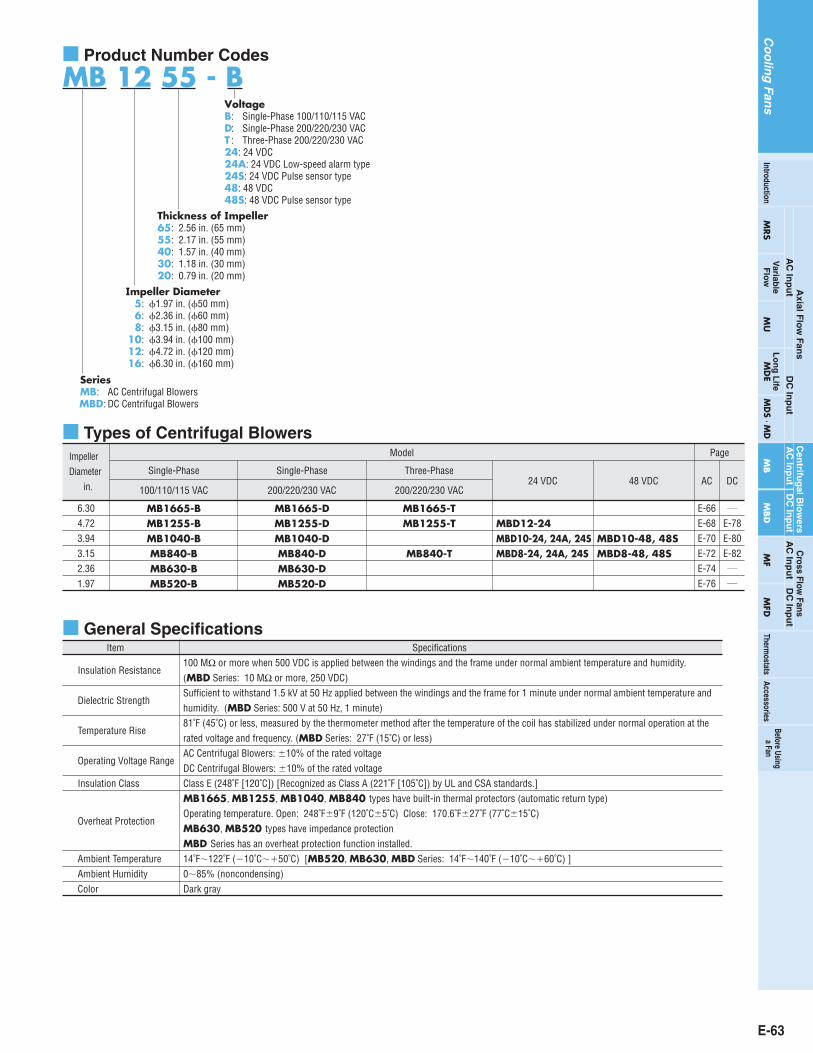
Product Number Codes
MB 12 55 - B
Thickness of Impeller65: 2.56 in. (65 mm)55: 2.17 in. (55 mm)40: 1.57 in. (40 mm)30: 1.18 in. (30 mm)20: 0.79 in. (20 mm)
Impeller Diameter5: 1.97 in. (50 mm)6: 2.36 in. (60 mm)8: 3.15 in. (80 mm)
10: 3.94 in. (100 mm)12: 4.72 in. (120 mm)16: 6.30 in. (160 mm)
SeriesMB: AC Centrifugal BlowersMBD: DC Centrifugal Blowers
VoltageB: Single-Phase 100/110/115 VACD: Single-Phase 200/220/230 VACT : Three-Phase 200/220/230 VAC24: 24 VDC24A: 24 VDC Low-speed alarm type24S: 24 VDC Pulse sensor type48: 48 VDC48S: 48 VDC Pulse sensor type
Impeller Diameter
in.
Single-Phase
100/110/115 VAC 200/220/230 VAC 200/220/230 VAC24 VDC AC DC
Single-Phase Three-Phase
Model Page
Types of Centrifugal Blowers
48 VDC
MB1665-BMB1255-BMB1040-BMB840-BMB630-BMB520-B
6.304.723.943.152.361.97
MB1665-DMB1255-DMB1040-DMB840-DMB630-DMB520-D
MB1665-TMBD12-24MBD10-24, 24A, 24SMBD8-24, 24A, 24S
E-66E-68E-70E-72E-74E-76
E-78/
E-80E-82/
/
MB1255-T
MB840-TMBD10-48, 48SMBD8-48, 48S
Item Specifications
Insulation Resistance100 MΩ or more when 500 VDC is applied between the windings and the frame under normal ambient temperature and humidity. (MBD Series: 10 MΩ or more, 250 VDC)
Dielectric StrengthSufficient to withstand 1.5 kV at 50 Hz applied between the windings and the frame for 1 minute under normal ambient temperature andhumidity. (MBD Series: 500 V at 50 Hz, 1 minute)
Temperature Rise81˚F (45˚C) or less, measured by the thermometer method after the temperature of the coil has stabilized under normal operation at therated voltage and frequency. (MBD Series: 27˚F (15˚C) or less)
Operating Voltage RangeAC Centrifugal Blowers: 10% of the rated voltageDC Centrifugal Blowers: 10% of the rated voltage
Insulation Class Class E (248˚F [120˚C]) [Recognized as Class A (221˚F [105˚C]) by UL and CSA standards.]MB1665, MB1255, MB1040, MB840 types have built-in thermal protectors (automatic return type)
Overheat ProtectionOperating temperature. Open: 248˚F9˚F (120˚C5˚C) Close: 170.6˚F27˚F (77˚C15˚C)MB630, MB520 types have impedance protectionMBD Series has an overheat protection function installed.
Ambient Temperature 14˚F122˚F (10˚C50˚C) [MB520, MB630, MBD Series: 14˚F140˚F (10˚C60˚C) ]Ambient Humidity 085% (noncondensing)Color Dark gray

E-64
Comparisons of Characteristics MB Series 50 Hz
0.1 0.2 0.3 0.4 0.5 0.6 0.7
Air Flow [CFM]
Air Flow [m3/min]
Stat
ic P
ress
ure
[Pa]
0.20
0.05
0.10
0.15
0.25
0.35
0.30
0.40St
atic
Pre
ssur
e [in
H2O]
155 10 20 25
0
MB630
MB520
0
10
20
30
40
50
60
70
0
60 Hz
0.1 0.2 0.3 0.4 0.5 0.6 0.7
Air Flow [CFM]
Air Flow [m3/min]
Stat
ic P
ress
ure
[Pa]
0.20
0.05
0.10
0.15
0.25
0.35
0.30
0.40
Stat
ic P
ress
ure
[inH2
O]
155 10 20 25
0
MB630
MB520
0
10
20
30
40
50
60
70
0
50 Hz
2.0 4.0 6.0 8.0 10.0 12.0 14.0
Air Flow [CFM]
Air Flow [m3/min]
0
700
600
500
400
300
200
100
Stat
ic P
ress
ure
[Pa]
2.0
3.0
0.5
1.0
1.5
2.5
3.5
4.0
0
Stat
ic P
ress
ure
[inH2
O]
300100 200 400 500
0
MB1665
MB1255
MB1040
MB840
60 Hz
2.0 4.0 6.0 8.0 10.0 12.0 14.0
Air Flow [CFM]
Air Flow [m3/min]
0
700
600
500
400
300
200
100
Stat
ic P
ress
ure
[Pa]
2.0
3.0
0.5
1.0
1.5
2.5
3.5
4.0
0
Stat
ic P
ress
ure
[inH2
O]
300100 200 400 500
0
MB1665MB1255
MB1040
MB840
MBD Series DC Centrifugal Blowers
50
100
150
200
250
300
350
400
MBD12
MBD10MBD8
Air Flow [CFM]80604020 100 120
0
0.8
0.6
0.2
0
0.4
1.0
1.2
1.4
1.6
1.8
2.0
2.2
Stat
ic P
ress
ure
[Pa]
Stat
ic P
ress
ure
[inH2
O]
3.0 3.52.52.01.51.00.5Air Flow [m3/min]
0
Co
olin
gFan
s
E-65
Co
olin
gFan
sTherm
ostats
Axial F
low
Fans
AC
Inp
ut
DC
Inp
ut
AC
Inp
ut
DC
Inp
ut
DC
Inp
ut
Cen
trifug
al Blo
wers
Cross Flow
FansA
C In
pu
t
MRS
Variab
leF
low
MU
Lo
ng
Life
MD
EM
DS M
DM
BM
BD
MF
MFD
AccessoriesIntroduction
Before Usinga Fan
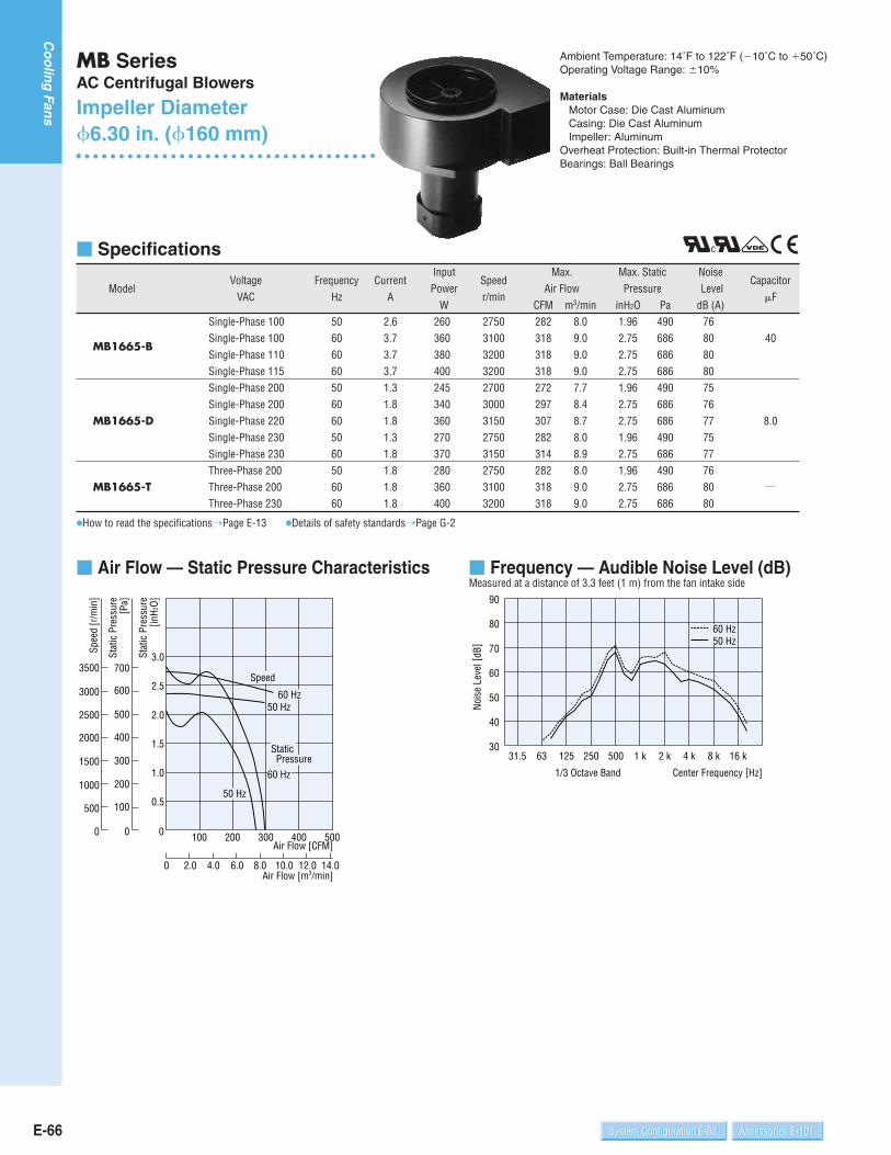
MB SeriesAC Centrifugal Blowers
Impeller Diameter6.30 in. (160 mm)
Ambient Temperature: 14˚F to 122˚F (10˚C to 50˚C)Operating Voltage Range: 10%
MaterialsMotor Case: Die Cast Aluminum Casing: Die Cast AluminumImpeller: Aluminum
Overheat Protection: Built-in Thermal ProtectorBearings: Ball Bearings
Specifications
Voltage Frequency CurrentInput
SpeedMax. Max. Static Noise
CapacitorModel
VAC Hz APower
r/minAir Flow Pressure Level
FW CFM m3/min inH2O Pa dB (A)
Single-Phase 100 50 2.6 260 2750 282 8.0 1.96 490 76
MB1665-BSingle-Phase 100 60 3.7 360 3100 318 9.0 2.75 686 80 40Single-Phase 110 60 3.7 380 3200 318 9.0 2.75 686 80Single-Phase 115 60 3.7 400 3200 318 9.0 2.75 686 80Single-Phase 200 50 1.3 245 2700 272 7.7 1.96 490 75Single-Phase 200 60 1.8 340 3000 297 8.4 2.75 686 76
MB1665-D Single-Phase 220 60 1.8 360 3150 307 8.7 2.75 686 77 8.0Single-Phase 230 50 1.3 270 2750 282 8.0 1.96 490 75Single-Phase 230 60 1.8 370 3150 314 8.9 2.75 686 77Three-Phase 200 50 1.8 280 2750 282 8.0 1.96 490 76
MB1665-T Three-Phase 200 60 1.8 360 3100 318 9.0 2.75 686 80 /
Three-Phase 230 60 1.8 400 3200 318 9.0 2.75 686 80
How to read the specificationsPage E-13 Details of safety standardsPage G-2
Air Flow — Static Pressure Characteristics
50 Hz
50 Hz
60 Hz
3500
3000
2500
2000
1500
1000
500
0
Spee
d [r
/min
]
Speed
Static Pressure
2.00 4.0 6.0 8.0 10.0 12.0 14.0Air Flow [m3/min]
Air Flow [CFM]
Stat
ic P
ress
ure
[inH
2O]
2.0
3.0
0.5
1.0
1.5
2.5
00
700
600
500
400
300
200
100
Stat
ic P
ress
ure
[Pa]
300100 200 400 500
60 Hz
Frequency — Audible Noise Level (dB)Measured at a distance of 3.3 feet (1 m) from the fan intake side
31.5 63 125 250 500 1 k 2 k 4 k 8 k 16 k
40
50
60
70
80
90
30
60 Hz50 Hz
1/3 Octave Band
Nois
e Le
vel [
dB]
Center Frequency [Hz]
RrVC
E-66 System Configuration E-62 Accessories E-101Accessories E-101System Configuration E-62
Co
olin
gFan
s

Thermostats (Sold Separately)
Thermostats make it possible for fans to operate only whencooling is necessary, thereby conserving energy.
Thermostats: AM1-WA1AM1-XA1
Page E-97
Connection Diagrams MB1665-B, D
How to connect a capacitorPage E-113
MB1665-T
Black
Red
WhiteLine
UV
W
Protective Earth (P.E.)
Capacitor
BlackRed
White
Line
Proctective Earth (P.E.)
Dimensions Scale 1/4, Unit = inch (mm)Weight: 11 lb. (5 kg)d E059
2.99 (76)3.27 (83)0.39 (10)
8.98 (228)
3.
54 (
90)
0.28 (7)
3.94
(100
)8.
94 (2
27)
0.96
(24.
5)
4.45 (113)8.74 (222)
(20)
22.5
3.66
(93)
5.
20 (
132)
3-Leads 12 inch (300 mm) LengthUL Style 3271, AWG 20
4.76(121)
M4
Air Flow
(25)
(30)
ProtectiveEarth mark
Protective Earth Terminal
0.39 (10)Unpainted
Rotation
0.98
1.18
0.51 (13)
1.57 (40)
0.79
(R1)R0.04
3.56
(90.
5)(R
1)R0.04
Panel Cut-Out Scale 1/4, Unit = inch (mm)
5.20
Intake side
2.99 (76)
3.66
(93)
Outlet side
(132)
Capacitor (Capacitor and capacitor cap are provided with single-phase blowers.)
0.24 (6)
A
CB
0.28
(7)
(20)0.
39(1
0)
0.169
AMP#187
0.16
(4)
B0.
59 (1
5)
R0.39 (10)
0.79(4.3)
Accessories (Sold Separately)
Mounting Bracket
MB1665-BMB1665-D
Model Capacitor
CH400CFAUL 2.28 (58) 1.61 (41) 2.28 (58) 6.7 (190)5.3 (150)1.97 (50)1.38 (35)2.28 (58)CH80BFAUL
Dimensions inch (mm)A B C
Weight oz. (g)
Item
Mounting BracketModel
PAS5ASafety Standards
/
Page
E-109
E-67
Co
olin
gFan
sTherm
ostats
Axial F
low
Fans
AC
Inp
ut
DC
Inp
ut
AC
Inp
ut
DC
Inp
ut
DC
Inp
ut
Cross Flow
FansA
C In
pu
t
MRS
Variab
leF
low
MU
Lo
ng
Life
MD
EM
DS M
DM
BM
BD
MF
MFD
AccessoriesIntroduction
Before Usinga Fan
Cen
trifug
al Blo
wers

E-68 System Configuration E-62 Accessories E-101Accessories E-101System Configuration E-62
Co
olin
gFan
s
MB SeriesAC Centrifugal Blowers
Impeller Diameter4.72 in. (120 mm)
Ambient Temperature: 14˚F to 122˚F (10˚C to 50˚C)Operating Voltage Range: 10%
MaterialsMotor Case: Die Cast Aluminum Casing: Die Cast AluminumImpeller: Aluminum
Overheat Protection: Built-in Thermal ProtectorBearings: Ball Bearings
Specifications
Voltage Frequency CurrentInput
SpeedMax. Max. Static Noise
CapacitorModel
VAC Hz APower
r/minAir Flow Pressure Level
FW CFM m3/min inH2O Pa dB (A)
Single-Phase 100 50 1.3 110 2850 155 4.4 1.24 309 67
MB1255-BSingle-Phase 100 60 1.6 150 3300 180 5.1 1.77 441 71
10Single-Phase 110 60 1.6 150 3300 180 5.1 1.77 441 71Single-Phase 115 60 1.6 150 3300 180 5.1 1.77 441 72Single-Phase 200 50 0.6 110 2850 155 4.4 1.26 314 67Single-Phase 200 60 0.8 145 3200 173 4.9 1.81 451 69
MB1255-D Single-Phase 220 60 0.8 145 3300 180 5.1 1.81 451 71 2.0Single-Phase 230 50 0.6 110 2900 159 4.5 1.26 314 67Single-Phase 230 60 0.8 150 3300 184 5.2 1.81 451 71Three-Phase 200 50 0.6 85 2850 155 4.4 1.26 314 67
MB1255-TThree-Phase 200 60 0.6 120 3280 177 5.0 1.81 451 70
/Three-Phase 220 60 0.65 125 3300 180 5.1 1.81 451 71Three-Phase 230 60 0.65 130 3300 184 5.2 1.81 451 71
How to read the specificationsPage E-13 Details of safety standardsPage G-2
Air Flow — Static Pressure Characteristics
50 Hz
60 Hz
50 Hz
60 Hz
1.00 2.0 3.0 4.0 5.0 6.0 7.0Air Flow [m3/min]
Air Flow [CFM]
Stat
ic P
ress
ure
[inH2
O]
15050 100 200 250
Stat
ic P
ress
ure
[Pa]
0
400
450
300
350
200
250
100
150
50
0.4
0.6
0.8
1.2
1.4
1.6
1.8
0.2
1.0
00
1000
1500
500
2000
2500
3000
3500
4000
4500
Spee
d [r
/min
]
Speed
Static Pressure
Frequency — Audible Noise Level (dB)Measured at a distance of 3.3 feet (1 m) from the fan intake side
31.5 63 125 250 500 1 k 2 k 4 k 8 k 16 k
30
40
50
60
70
80
20
60 Hz50 Hz
1/3 Octave Band
Nois
e Le
vel [
dB]
Center Frequency [Hz]
RrVC

Thermostats (Sold Separately)
Thermostats make it possible for fans to operate only whencooling is necessary, thereby conserving energy.
Thermostats: AM1-WA1AM1-XA1
Page E-97
Connection Diagrams MB1255-B, D Type
How to connect a capacitorPage E-113
MB1255-T Type
Black
Red
White
Protective Earth (P.E.)
UV Line
W
Capacitor
BlackRed
White
Line
Protective Earth (P.E.)
Dimensions Scale 1/4, Unit = inch (mm)Weight: 8.8 lb. (4 kg)d E060
0.71(18)
3.
78 (
96)
2.28 (58) 0.39 (10)2.56 (65)
7.05 (179)
3.09
(78.
5)
4.
02 (
102)
0.51 (13)
6.85 (174)3.54 (90)
6.93
(176
)3.
35 (8
5)0.
59(1
5) 3.31
3-Leads 12 inch (300 mm) LengthUL Style 3271, AWG 20
0.26 (6.5) 0.08 (2)
22.5
1.18
(30)
0.98(25)
Air Flow
0.39 (10) Unpainted
Rotation
2.97
(75.
5)
R0.04(R1)
R0.04
(R1)
Protective Earth Mark
Protective EarthTerminal M4
(84)
Panel Cut-Out Scale 1/4, Unit = inch (mm)
3.78
2.28 (58)
3.09
(78.
5)
Outlet side Intake side
(96)
Capacitor (Capacitor and capacitor cap are provided with single-phase blowers.)
0.169(20)
A
C ( 1
0)
B0.
18(4
.5)
0.16
(4)
0.39
( 10) 0.24
(6)
0.79(4.3)
B0.3
9AMP#187
MB1255-BMB1255-D
Model Capacitor
CH100CFAUL 1.89 (48) 0.89 (22.5) 1.24 (31.5) 1.41 (40)1.41 (40)1.14 (29)00.75 (19)01.89 (48)CH20BFAUL
Dimensions inch (mm)A B C
Weightoz. (g)
Accessories (Sold Separately)
MountingBracket
Duct Joint
Filter
A finger guard can be installed in place of the filter.
Item
Finger Guard
Filter
Mounting Bracket
Duct Joint
Model
FGB12FLB12PAS6AFD12
Safety Standards
/
/
/
Page
E-104
E-106
E-109
E-110
E-69
Co
olin
gFan
sTherm
ostats
Axial F
low
Fans
AC
Inp
ut
DC
Inp
ut
AC
Inp
ut
DC
Inp
ut
DC
Inp
ut
Cross Flow
FansA
C In
pu
t
MRS
Variab
leF
low
MU
Lo
ng
Life
MD
EM
DS M
DM
BM
BD
MF
MFD
AccessoriesIntroduction
Before Usinga Fan
Cen
trifug
al Blo
wers
These products have been designed to pass tests set forth under the UL andCSA standards for equipment used in fans. They conform to the standards onlywhen used with an O.
E-70 System Configuration E-62 Accessories E-101Accessories E-101System Configuration E-62
Co
olin
gFan
s
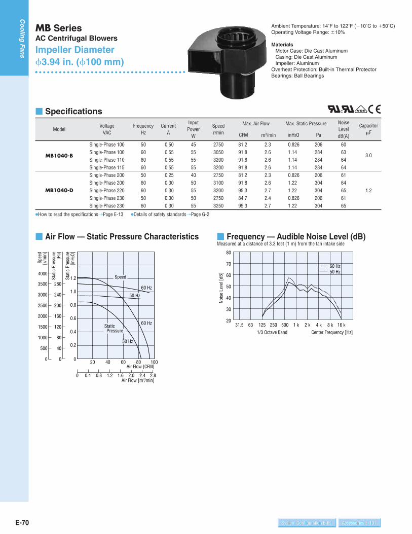
MB SeriesAC Centrifugal Blowers
Impeller Diameter3.94 in. (100 mm)
Ambient Temperature: 14˚F to 122˚F (10˚C to 50˚C)Operating Voltage Range: 10%
MaterialsMotor Case: Die Cast Aluminum Casing: Die Cast AluminumImpeller: Aluminum
Overheat Protection: Built-in Thermal ProtectorBearings: Ball Bearings
Frequency — Audible Noise Level (dB)Measured at a distance of 3.3 feet (1 m) from the fan intake side
31.5 63 125 250 500 1 k 2 k 4 k 8 k 16 k
30
40
50
60
70
80
1/3 Octave Band
Nois
e Le
vel [
dB]
Center Frequency [Hz]
20
60 Hz50 Hz
RrVC Specifications
Model
How to read the specificationsPage E-13 Details of safety standardsPage G-2
VoltageVAC
FrequencyHz
MB1040-B
MB1040-D
Single-Phase 100Single-Phase 100Single-Phase 110Single-Phase 115Single-Phase 200Single-Phase 200Single-Phase 220Single-Phase 230Single-Phase 230
506060605060605060
CurrentA
0.500.550.550.550.250.300.300.300.30
InputPower
W
455555554050555055
Speedr/min
275030503200320027503100320027503250
CFM
Max. Air Flow
81.291.891.891.881.291.895.384.795.3
m3/min inH2O
Max. Static Pressure
Pa
2.32.62.62.62.32.62.72.42.7
0.8261.141.141.140.8261.221.220.8261.22
206284284284206304304206304
Noise LeveldB(A)
606364646164656165
CapacitorF
3.0
1.2
Air Flow — Static Pressure Characteristics
0
500
1000
1500
2000
2500
3000
3500
4000
50 Hz
50 Hz
60 Hz
60 Hz
Speed
Static Pressure
2.82.42.01.61.20.80.40Air Flow [m3/min]
Air Flow [CFM]6020 40 80 100
Spee
d [r
/min
]
Stat
ic P
ress
ure
[inH
2O]
0.8
1.2
0.2
0.4
0.6
1.0
00
40
80
120
160
200
240
280
Stat
ic P
ress
ure
[Pa]
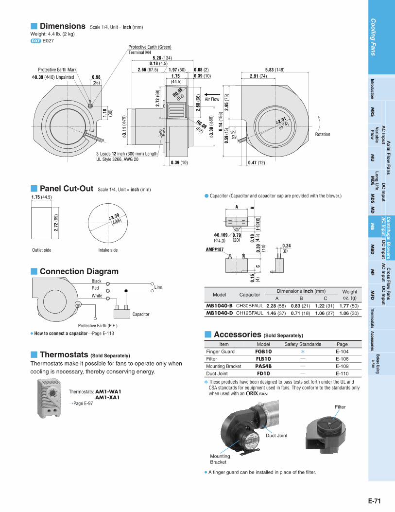
Panel Cut-Out Scale 1/4, Unit = inch (mm)
3.39
1.75 (44.5)
2.72
(69)
Outlet side Intake side
(86)
Dimensions Scale 1/4, Unit = inch (mm)Weight: 4.4 lb. (2 kg)d E027
0.39 (10) Unpainted
Protective Earth Mark
0.98(25)
Protective Earth (Green)Terminal M4
1.18
(30)
3.
11 (
79)
5.28 (134)
2.66 (67.5)0.18 (4.5)
1.97 (50) 0.08 (2)0.39 (10)1.75
(44.5)
2.72
(69)
R0.08
(R2)
2.60
(66)
R0.08(R2)
3.
39 (
86)
0.39 (10)
3-Leads 12 inch (300 mm) Length UL Style 3266, AWG 20
0.47 (12)
6.14
(156
)0.
59 (1
5)2.
95 (7
5)
22.5
˚
2.91
(74)
Rotation
2.91 (74)5.83 (148)
Air Flow
Connection Diagram
How to connect a capacitorPage E-113
Capacitor
BlackRed
White
Line
Protective Earth (P.E.)
Accessories (Sold Separately)
Model
MB1040-BMB1040-D
Capacitor
CH30BFAUL
CH12BFAUL
Dimensions inch (mm)
A B C
2.28 (58)
1.46 (37)
0.83 (21)
0.71 (18)
1.22 (31)
1.06 (27)
Weightoz. (g)
1.77 (50)
1.06 (30)
MountingBracket
Duct Joint
Filter
A finger guard can be installed in place of the filter.
Thermostats (Sold Separately)
Thermostats make it possible for fans to operate only whencooling is necessary, thereby conserving energy.
Thermostats: AM1-WA1AM1-XA1
Page E-97
Capacitor (Capacitor and capacitor cap are provided with the blower.)
0.169(20)
A
CB
0.18
(4.5
)0.
16(4
)
AMP#187 0.39
( 10) 0.24
(6)
0.79(4.3)
B0.3
9(10)
Item
Finger Guard
Filter
Mounting Bracket
Duct Joint
Model
FGB10FLB10PAS4BFD10
Safety Standards
/
/
/
Page
E-104
E-106
E-109
E-110
E-71
Co
olin
gFan
sTherm
ostats
Axial F
low
Fans
AC
Inp
ut
DC
Inp
ut
AC
Inp
ut
DC
Inp
ut
DC
Inp
ut
Cross Flow
FansA
C In
pu
t
MRS
Variab
leF
low
MU
Lo
ng
Life
MD
EM
DS M
DM
BM
BD
MF
MFD
AccessoriesIntroduction
Before Usinga Fan
Cen
trifug
al Blo
wers
These products have been designed to pass tests set forth under the UL andCSA standards for equipment used in fans. They conform to the standards onlywhen used with an O.

E-72 System Configuration E-62 Accessories E-101Accessories E-101System Configuration E-62
Co
olin
gFan
s
MB SeriesAC Centrifugal Blowers
Impeller Diameter3.15 in. (80 mm)
Ambient Temperature: 14˚F to 122˚F (10˚C to 50˚C)Operating Voltage Range: 10%
MaterialsMotor Case: Die Cast Aluminum Casing: Die Cast AluminumImpeller: Aluminum
Overheat Protection: Built-in Thermal ProtectorBearings: Ball Bearings
Frequency — Audible Noise Level (dB)Measured at a distance of 3.3 feet (1 m) from the fan intake side
31.5 63 125 250 500 1 k 2 k 4 k 8 k 16 k
10
20
30
40
50
60
0
1/3 Octave Band
Nois
e Le
vel [
dB]
Center Frequency [Hz]
60 Hz50 Hz
RrDC Specifications
Model
MB840-T is conformed by UL and CSA standards. How to read the specificationsPage E-13 Details of safety standardsPage G-12
VoltageVAC
FrequencyHz
MB840-B
MB840-D
MB840-T
Single-Phase 100Single-Phase 100Single-Phase 110Single-Phase 115Single-Phase 200Single-Phase 200Single-Phase 220Single-Phase 230Single-Phase 230Three-Phase 200Three-Phase 200Three-Phase 220Three-Phase 230
50606060506060506050606060
CurrentA
0.290.370.370.370.140.180.180.150.180.120.150.150.15
InputPower
W
28323536283235353625283030
Speedr/min
2800315033003350280032003350285033502800320033503350
CFM
Max. Air Flow
56.563.563.563.556.563.563.556.563.556.563.563.563.5
m3/min inH2O
Max. Static Pressure
Pa
1.61.81.81.81.61.81.81.61.81.61.81.81.8
0.610.8860.9060.9060.610.8860.9060.630.9060.610.8860.9060.906
152221226226152221226157226152221226226
Noise LeveldB(A)
55585959555859555955585959
CapacitorF
1.5
2.5
/
Air Flow — Static Pressure Characteristics
50 Hz
50 Hz
60 Hz
60 Hz
3500
3000
2500
2000
1500
1000
500
0
4000
Spee
d [r
/min
]
Stat
ic P
ress
ure
[inH
2O]
0.8
1.2
0.2
0.4
0.6
1.0
00
40
80
120
160
200
240
280
Stat
ic P
ress
ure
[Pa]
Speed
Static Pressure
2.82.42.01.61.20.80.40Air Flow [m3/min]
Air Flow [CFM]6020 40 80 100
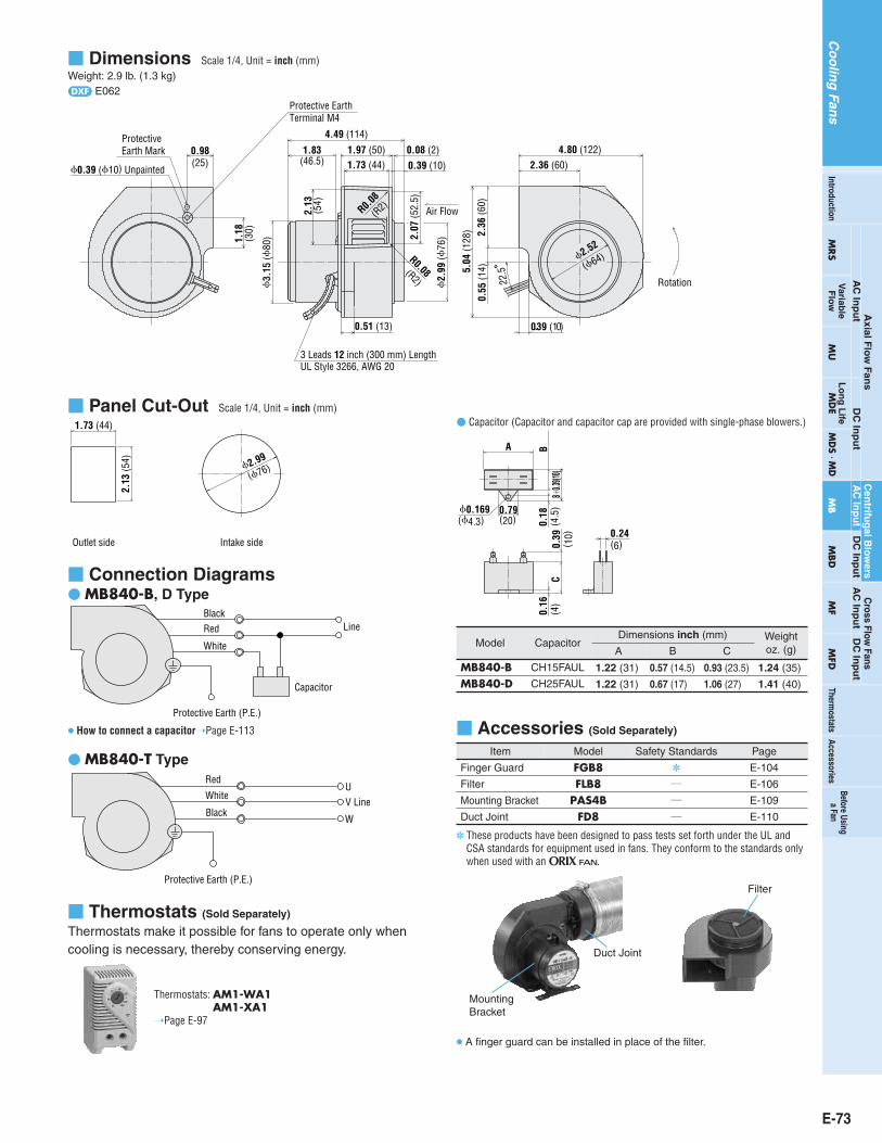
Panel Cut-Out Scale 1/4, Unit = inch (mm)
1.73 (44)
2.13
(54)
Outlet side Intake side
2.99
(76)
Dimensions Scale 1/4, Unit = inch (mm)Weight: 2.9 lb. (1.3 kg)d E062
4.80 (122)2.36 (60)
5.04
(128
)
4.49 (114)
1.97 (50)1.73 (44)
2.13
(54)
3.
15 (
80)
0.51 (13)
0.39 (10)
2.36
(60)
0.55
(14)
2.52
(64)
0.39 (10)
2.
99 (
76)
0.08 (2)
22.5
0.98
1.18
0.39 (10) Unpainted
ProtectiveEarth Mark
(25)
(30)
Protective EarthTerminal M4
Air Flow
Rotation
3 Leads 12 inch (300 mm) LengthUL Style 3266, AWG 20
R0.08
(R2)
R0.08(R2)
2.07
(52.
5)
1.83(46.5)
Connection Diagrams MB840-B, D Type
How to connect a capacitorPage E-113
Capacitor
BlackRed
White
Line
Protective Earth (P.E.)
MB840-T Type
Black
Red
White
Protective Earth (P.E.)
UV Line
W
Accessories (Sold Separately)
Model
MB840-BMB840-D
Capacitor
CH15FAUL
CH25FAUL
Dimensions inch (mm)
A B C
1.22 (31)
1.22 (31)
0.57 (14.5)
0.67 (17)
0.93 (23.5)
1.06 (27)
Weightoz. (g)
1.24 (35)
1.41 (40)
MountingBracket
Duct Joint
Filter
A finger guard can be installed in place of the filter.
Capacitor (Capacitor and capacitor cap are provided with single-phase blowers.)
0.169(20)
A
CB
0.18
(4.5
)0.
16(4
)0.
39( 1
0) 0.24(6)
0.79(4.3)
B0.3
9(10)
Thermostats (Sold Separately)
Thermostats make it possible for fans to operate only whencooling is necessary, thereby conserving energy.
Thermostats: AM1-WA1AM1-XA1
Page E-97
Item
Finger Guard
Filter
Mounting Bracket
Duct Joint
Model
FGB8FLB8
PAS4BFD8
Safety Standards
/
/
/
Page
E-104
E-106
E-109
E-110
E-73
Co
olin
gFan
sTherm
ostats
Axial F
low
Fans
AC
Inp
ut
DC
Inp
ut
AC
Inp
ut
DC
Inp
ut
DC
Inp
ut
Cross Flow
FansA
C In
pu
t
MRS
Variab
leF
low
MU
Lo
ng
Life
MD
EM
DS M
DM
BM
BD
MF
MFD
AccessoriesIntroduction
Before Usinga Fan
Cen
trifug
al Blo
wers
These products have been designed to pass tests set forth under the UL andCSA standards for equipment used in fans. They conform to the standards onlywhen used with an O.

E-74 System Configuration E-62 Accessories E-101Accessories E-101System Configuration E-62
Co
olin
gFan
s
MB SeriesAC Centrifugal Blowers
Impeller Diameter2.36 in. (60 mm)
Ambient Temperature: 14˚F to 122˚F (10˚C to 50˚C)Operating Voltage Range: 10%
MaterialsMotor Case: Die Cast Aluminum Casing: Die Cast AluminumImpeller: Aluminum
Overheat Protection: Impedance ProtectionBearings: Ball Bearings
Frequency — Audible Noise Level (dB)Measured at a distance of 3.3 feet (1 m) from the fan intake side
50 Hz 60 Hz
31.5 63 125 250 500 1 k 2 k 4 k 8 k 16 k
10
20
30
40
50
60
0
1/3 Octave Band
Nois
e Le
vel [
dB]
Center Frequency [Hz]
RrVC Specifications
Model
How to read the specificationsPage E-13 Details of safety standardsPage G-12
VoltageVAC
FrequencyHz
MB630-B
MB630-D
Single-Phase 100Single-Phase 100Single-Phase 110Single-Phase 115Single-Phase 200Single-Phase 200Single-Phase 220Single-Phase 230Single-Phase 230
506060605060605060
CurrentA
0.110.110.120.120.080.080.080.090.08
InputPower
W
8.08.09.5
10.012.011.013.016.014.0
Speedr/min
230019002300250025002600290026002900
CFM
Max. Air Flow
15.512.715.917.317.317.719.417.719.4
m3/min inH2O
Max. Static Pressure
Pa
0.440.360.450.490.490.500.550.500.55
0.2130.3050.3090.3170.2250.3330.3330.2250.333
537677795683835683
Noise LeveldB(A)
373338403839423943
Air Flow — Static Pressure Characteristics
50 Hz
60 Hz50 Hz
60 Hz
3500
3000
2500
2000
1500
1000
500
0
4000
Spee
d [r
/min
]
Stat
ic P
ress
ure
[inH
2O]
0.20
0.30
0.05
0.10
0.15
0.25
0
70
80
60
50
40
30
20
10
0
Stat
ic P
ress
ure
[Pa]
Speed
Static Pressure
0.10 0.2 0.3 0.4 0.5 0.6 0.7Air Flow [m3/min]
Air Flow [CFM]155 10 20 25

Panel Cut-Out Scale 1/4, Unit = inch (mm)
1.89 2.64
120
1.38(35)
1.42
(36)
0.138 (3.5)
Outlet side Intake side
(48) (67)
3 Holes
Dimensions Scale 1/4, Unit = inch (mm)Weight: 1.1 lb. (0.5 kg)d E063
2.95 (75)1.57 (40)
0.24 (6)0.04 (1)
1.
89(
48)
2.
36(
60)
1.42
(36)
1.38(35)
0.35 (9) 0.04 (1)
3.54 (90)1.81 (46)
3.54
(90) 1.
57 (4
0)0.
39 (1
0)
0.31 (8)
2.64(67)
1.65
(42)0.28(7)
M3 P0.5-3 places
22.52 Leads 12 inch (300 mm) LengthUL Style 3266, AWG 20
0.79
(20)
0.59 (15)
Air Flow
0.39 (10) Unpainted
Rotation
Protective Earth Mark
ProtectiveEarth Terminal M4
R0.04 (R1)
R0.04(R1)
1.38
(3
5)
Connection Diagram
Line
Protective Earth (P.E.)
Accessories (Sold Separately)
Mounting Bracket
Thermostats (Sold Separately)
Thermostats make it possible for fans to operate only whencooling is necessary, thereby conserving energy.
Thermostats: AM1-WA1AM1-XA1
Page E-97
Item
Mounting Bracket
Model
PAS2BSafety Standards
/
Page
E-109
E-75
Co
olin
gFan
sTherm
ostats
Axial F
low
Fans
AC
Inp
ut
DC
Inp
ut
AC
Inp
ut
DC
Inp
ut
DC
Inp
ut
Cross Flow
FansA
C In
pu
t
MRS
Variab
leF
low
MU
Lo
ng
Life
MD
EM
DS M
DM
BM
BD
MF
MFD
AccessoriesIntroduction
Before Usinga Fan
Cen
trifug
al Blo
wers
E-76 System Configuration E-62 Accessories E-101Accessories E-101System Configuration E-62
Co
olin
gFan
s
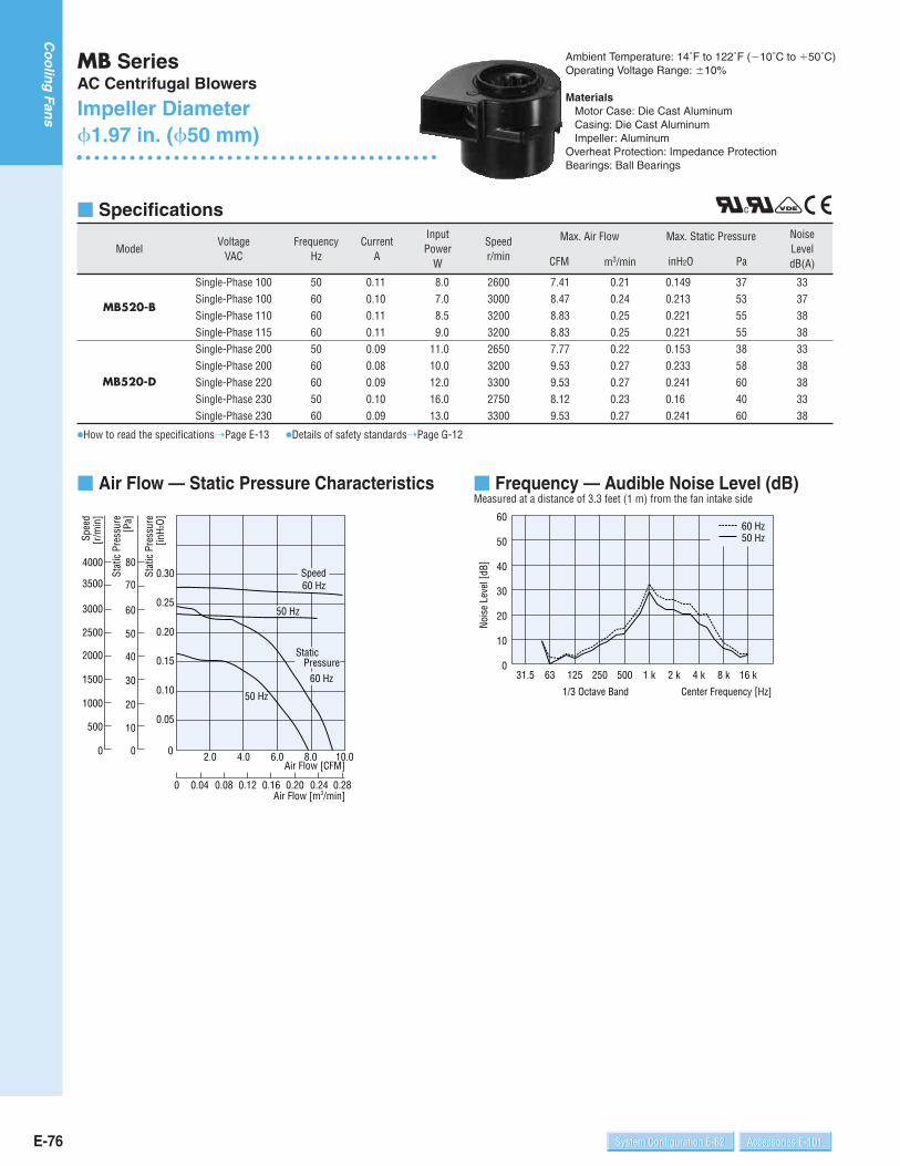
MB SeriesAC Centrifugal Blowers
Impeller Diameter1.97 in. (50 mm)
Ambient Temperature: 14˚F to 122˚F (10˚C to 50˚C)Operating Voltage Range: 10%
MaterialsMotor Case: Die Cast Aluminum Casing: Die Cast AluminumImpeller: Aluminum
Overheat Protection: Impedance ProtectionBearings: Ball Bearings
Frequency — Audible Noise Level (dB)Measured at a distance of 3.3 feet (1 m) from the fan intake side
50 Hz60 Hz
31.5 63 125 250 500 1 k 2 k 4 k 8 k 16 k
10
20
30
40
50
60
0
1/3 Octave Band
Nois
e Le
vel [
dB]
Center Frequency [Hz]
RrVC Specifications
Model
How to read the specificationsPage E-13 Details of safety standardsPage G-12
VoltageVAC
FrequencyHz
MB520-B
MB520-D
Single-Phase 100Single-Phase 100Single-Phase 110Single-Phase 115Single-Phase 200Single-Phase 200Single-Phase 220Single-Phase 230Single-Phase 230
506060605060605060
CurrentA
0.110.100.110.110.090.080.090.100.09
InputPower
W
8.07.08.59.0
11.010.012.016.013.0
Speedr/min
260030003200320026503200330027503300
CFM
Max. Air Flow
7.418.478.838.837.779.539.538.129.53
m3/min inH2O
Max. Static Pressure
Pa
0.210.240.250.250.220.270.270.230.27
0.1490.2130.2210.2210.1530.2330.2410.160.241
375355553858604060
Noise LeveldB(A)
333738383338383338
Air Flow — Static Pressure Characteristics
50 Hz
50 Hz
60 Hz
60 Hz3500
3000
2500
2000
1500
1000
500
0
4000
Spee
d [r
/min
]
Stat
ic P
ress
ure
[inH
2O]
0.20
0.30
0.05
0.10
0.15
0.25
0
70
80
60
50
40
30
20
10
0
Stat
ic P
ress
ure
[Pa]
Speed
Static Pressure
0.280.240.200.160.120.080.040Air Flow [m3/min]
Air Flow [CFM]6.02.0 4.0 8.0 10.0
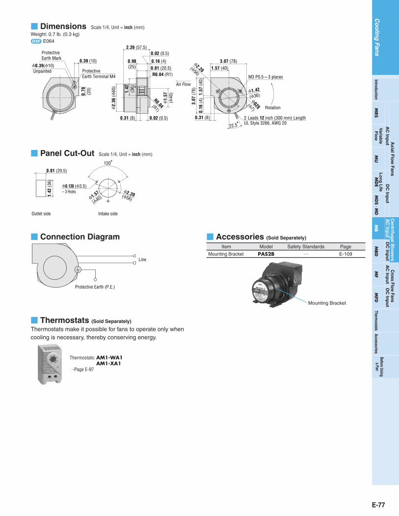
Panel Cut-Out Scale 1/4, Unit = inch (mm)
0.81 (20.5)
1.42
(36)
1.57 2.20
120
0.138 (3.5)– 3 Holes
Outlet side Intake side
(40) (56)
Dimensions Scale 1/4, Unit = inch (mm)Weight: 0.7 lb. (0.3 kg)d E064
1.
57(
40)
0.81 (20.5)0.98(25)
2.26 (57.5)
1.42
(36)
2.
36 (
60)
0.31 (8) 0.02 (0.5)
0.16 (4)
0.02 (0.5)
0.39 (10)
0.79
(20)
2.20(56)
1.42
(36)
22.5
1.57 (40)3.07 (78)
1.57
(40)
0.16
(4)
3.07
(78)
0.31 (8) 2-Leads 12 inch (300 mm) LengthUL Style 3266, AWG 20
0.28(7)
M3 P0.53 places
Air Flow
Rotation
0.39(10) Unpainted
ProtectiveEarth Mark
ProtectiveEarth Terminal M4
R0.04(R1)
R0.04 (R1)
Connection Diagram
Line
Protective Earth (P.E.)
Accessories (Sold Separately)
Mounting Bracket
Thermostats (Sold Separately)
Thermostats make it possible for fans to operate only whencooling is necessary, thereby conserving energy.
Thermostats: AM1-WA1AM1-XA1
Page E-97
Item
Mounting Bracket
Model
PAS2BSafety Standards
/
Page
E-109
E-77
Co
olin
gFan
sTherm
ostats
Axial F
low
Fans
AC
Inp
ut
DC
Inp
ut
AC
Inp
ut
DC
Inp
ut
DC
Inp
ut
Cross Flow
FansA
C In
pu
t
MRS
Variab
leF
low
MU
Lo
ng
Life
MD
EM
DS M
DM
BM
BD
MF
MFD
AccessoriesIntroduction
Before Usinga Fan
Cen
trifug
al Blo
wers

MBD SeriesDC Centrifugal Blowers
Impeller Diameter4.72 in. (120 mm)
Ambient Temperature: 14˚F to 140˚F (10˚C to 60˚C)Operating Voltage Range: 10%
MaterialsMotor Case: Die Cast Aluminum Casing: Die Cast AluminumImpeller: AluminumOverheat Protection: Built-in Overheat Protection CircuitBearings: Ball Bearings
Frequency — Audible Noise Level (dB)Measured at a distance of 3.3 feet (1 m) from the fan intake side
31.5 63 125 250 500 1 k 2 k 4 k 8 k 16 k
10
20
30
40
50
60
0
1/3 Octave Band
Nois
e Le
vel [
dB]
Center Frequency [Hz]
E-78 System Configuration E-62 Accessories E-101Accessories E-101System Configuration E-62
Co
olin
gFan
s
Specifications
Model
How to read the specificationsPage E-13
Rated VoltageVDC
MBD12-24 24
Rated CurrentA
1.5
Rated Speedr/min
1900CFM
Max. Air Flow
106m3/min inH2O
Max. Static PressurePa
3.0 1.49 372
Noise LeveldB(A)
58
Air Flow — Static Pressure Characteristics
0
500
1000
1500
2000
2500
3000
4000
3500
3.02.52.01.51.00.50Air Flow [m3/min]
Air Flow [CFM]80604020 100 120
0.8
0.6
0.2
0
0.4
1.0
1.2
1.4
1.6
Stat
ic P
ress
ure
[inH
2O]
0
50
100
150
200
250
300
350
400
Stat
ic P
ress
ure
[Pa]
Spee
d [r
/min
]
Speed
Static Pressure

Panel Cut-Out Scale 1/4, Unit = inch (mm)
3.78
2.28 (58)
3.09
(78.
5)
Outlet side Intake side
(96)
Dimensions Scale 1/4, Unit = inch (mm)Weight: 3.3 lb. (1.5 kg)d E031
3.31
Air Flow
3.54 (90)6.85 (174)
3.35
(85)
0.59
(15)6.
93 (1
76)
0.71 (18)
3.
78
3.
15
3.09
(78.
5)2.28 (58)
22.5
2.56 (65)0.39 (10)
5.18 (131.5)
2-Leads 12 inch (300 mm) LengthUL Style 1007,AWG 24
0.08 (2)
Rotation
(80
)
(96
)
(84)
R0.04
(R1)
R0.04(R1)
2.97
(75.
5)
Connection Diagram
Black
Red
GND
24 VDC
Accessories (Sold Separately)
Item
Finger Guard
Filter
Mounting Bracket
Duct Joint
Model
FGB12FLB12PAS4BFD12
Safety Standards
/
/
/
Page
E-104
E-106
E-109
E-110
Mounting Bracket
Duct Joint
Filter
A finger guard can be installed in place of the filter.
E-79
Co
olin
gFan
sTherm
ostats
Axial F
low
Fans
AC
Inp
ut
DC
Inp
ut
AC
Inp
ut
DC
Inp
ut
DC
Inp
ut
Cross Flow
FansA
C In
pu
t
MRS
Variab
leF
low
MU
Lo
ng
Life
MD
EM
DS M
DM
BM
BD
MF
MFD
AccessoriesIntroduction
Before Usinga Fan
These products have been designed to pass tests set forth under the UL andCSA standards for equipment used in fans. They conform to the standards onlywhen used with an O.
Cen
trifug
al Blo
wers
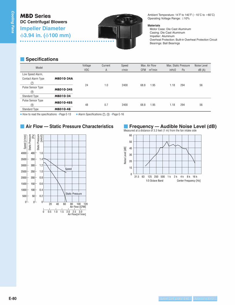
MBD SeriesDC Centrifugal Blowers
Impeller Diameter3.94 in. (100 mm)
Specifications
Air Flow — Static Pressure Characteristics
0.50 1.0 1.5 2.0 2.5 3.0Air Flow[m3/min]
0
50
100
150
200
250
300
350
400
Static Pressure
Speed
500
0.41000
1500
2000
2500
3000
3500
4000
0.6
0.8
1.0
1.2
1.4
0.2
1.6
Spee
d [r
/min
]
Air Flow [CFM]
Stat
ic P
ress
ure
[inH
2O]
Stat
ic P
ress
ure
[Pa]
0 020 40 60 80 100 120
E-80 System Configuration E-62 Accessories E-101Accessories E-101System Configuration E-62
Co
olin
gFan
s
Ambient Temperature: 14˚F to 140˚F (10˚C to 60˚C)Operating Voltage Range: 10%
MaterialsMotor Case: Die Cast Aluminum Casing: Die Cast AluminumImpeller: AluminumOverheat Protection: Built-in Overheat Protection CircuitBearings: Ball Bearings
Frequency — Audible Noise Level (dB)Measured at a distance of 3.3 feet (1 m) from the fan intake side
31.5 63 125 250 500 1 k 2 k 4 k 8 k 16 k
10
20
30
40
50
60
0
1/3 Octave Band
Nois
e Le
vel [
dB]
Center Frequency [Hz]
ModelVoltage Current Speed Max. Air Flow Max. Static Pressure Noise Level
VDC A r/min CFM m3/min inH2O Pa dB (A)Low Speed Alarm,Contact Alarm Type MBD10-24A
24 1.0 2400 68.8 1.95 1.18 294 56
Pulse Sensor TypeMBD10-24S
Standard Type MBD10-24Pulse Sensor Type
MBD10-48S 48 0.7 2400 68.8 1.95 1.18 294 56
Standard Type MBD10-48
How to read the specificationsPage E-13 Alarm Specifications , Page E-16
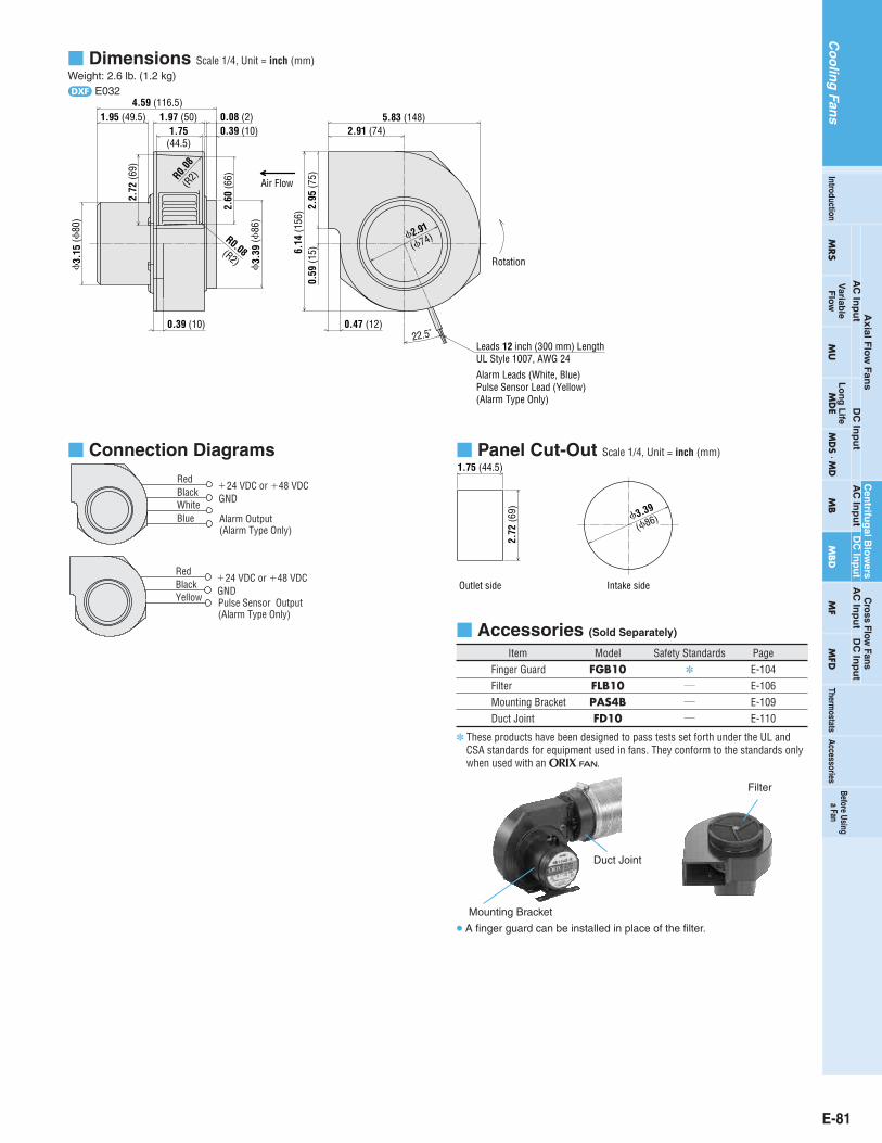
Dimensions Scale 1/4, Unit = inch (mm)Weight: 2.6 lb. (1.2 kg)d E032
22.5˚
4.59 (116.5)1.95 (49.5) 1.97 (50)
1.75(44.5)
0.39 (10)0.08 (2)
Air Flow
2.72
(69)
2.60
(66)R0.
08(R
2)
R0.08(R2)
3.39
(86
)
0.39 (10)
3.
15 (
80)
6.14
(156
) 2.95
(75)
0.59
(15)
0.47 (12)
Leads 12 inch (300 mm) LengthUL Style 1007, AWG 24
Alarm Leads (White, Blue)Pulse Sensor Lead (Yellow)(Alarm Type Only)
Rotation
5.83 (148)2.91 (74)
2.91
(74)
Panel Cut-Out Scale 1/4, Unit = inch (mm)
3.39
1.75 (44.5)
2.72
(69)
Outlet side Intake side
(86)
Connection Diagrams
BlackRed
GNDPulse Sensor Output(Alarm Type Only)
24 VDC or 48 VDC
Yellow
BlackRed
GND
Alarm Output(Alarm Type Only)
24 VDC or 48 VDC
BlueWhite
Accessories (Sold Separately)
Item Model Safety Standards PageFinger Guard FGB10 E-104Filter FLB10 / E-106Mounting Bracket PAS4B / E-109Duct Joint FD10 / E-110
Mounting Bracket
Duct Joint
Filter
A finger guard can be installed in place of the filter.
E-81
Co
olin
gFan
sTherm
ostats
Axial F
low
Fans
AC
Inp
ut
DC
Inp
ut
AC
Inp
ut
DC
Inp
ut
DC
Inp
ut
Cross Flow
FansA
C In
pu
t
MRS
Variab
leF
low
MU
Lo
ng
Life
MD
EM
DS M
DM
BM
BD
MF
MFD
AccessoriesIntroduction
Before Usinga Fan
These products have been designed to pass tests set forth under the UL andCSA standards for equipment used in fans. They conform to the standards onlywhen used with an O.
Cen
trifug
al Blo
wers

E-82 System Configuration E-62 Accessories E-101Accessories E-101System Configuration E-62
Co
olin
gFan
s
MBD SeriesDC Centrifugal Blowers
Impeller Diameter3.15 in. (80 mm)
Specifications
Air Flow — Static Pressure Characteristics
0.50 1.0 1.5 2.0 2.5 3.0Air Flow [m3/min]
Static Pressure
Speed
500
0.41000
1500
2000
2500
3000
3500
4000
0.6
0.8
1.0
1.2
1.4
1.6
0.2
Spee
d [r
/min
]
Air Flow [CFM]
Stat
ic P
ress
ure
[inH
2O]
0
50
100
150
200
250
300
350
400
Stat
ic P
ress
ure
[Pa]
0 020 40 60 80 100 120
Frequency — Audible Noise Level (dB)Measured at a distance of 3.3 feet (1 m) from the fan intake side
Center Frequency [Hz]1/3 Octave Band31.5 63 125 250 500 1 k 2 k 4 k 8 k 16 k0
10
20
30
40
50
60
Nois
e Le
vel [
dB]
Ambient Temperature: 14˚F to 140˚F (10˚C to 60˚C)Operating Voltage Range: 10%
MaterialsMotor Case: Die Cast Aluminum Casing: Die Cast AluminumImpeller: AluminumOverheat Protection: Built-in Overheat Protection CircuitBearings: Ball Bearings
ModelVoltage Current Speed Max. Air Flow Max. Static Pressure Noise Level
VDC A r/min CFM m3/min inH2O Pa dB (A)Low Speed Alarm,Contact Alarm Type MBD8-24A
24 0.7 2600 51.2 1.45 0.786 196 51Pulse Sensor Type
MBD8-24S
Standard Type MBD8-24Pulse Sensor Type
MBD8-48S 48 0.5 2600 51.2 1.45 0.786 196 51
Standard Type MBD8-48
How to read the specificationsPage E-13 Alarm Specifications , Page E-16
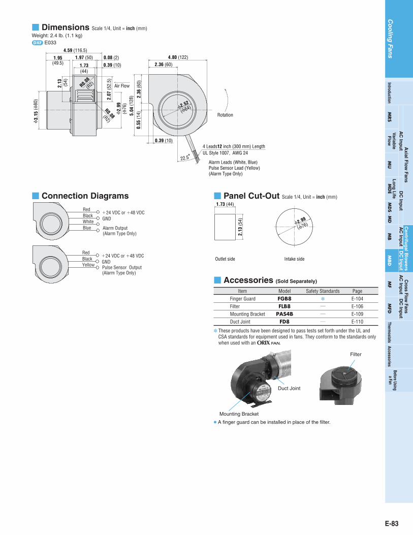
Dimensions Scale 1/4, Unit = inch (mm)Weight: 2.4 lb. (1.1 kg)d E033
22.5
Air Flow
2.36 (60)4.80 (122)
2.36
(60)
0.55
(14)5.
04 (1
28)
0.39 (10)
2.
99
3.
15 (
80)
1.95(49.5)
2.13
(54)
1.73(44)
1.97 (50)
0.39 (10)
4.59 (116.5)0.08 (2)
2.52
(76
)
(64)
Rotation
4 Leads12 inch (300 mm) Length UL Style 1007, AWG 24
Alarm Leads (White, Blue)Pulse Sensor Lead (Yellow)(Alarm Type Only)
R0.08
(R2)
R0.08(R2)
2.07
(52.
5)
Panel Cut-Out Scale 1/4, Unit = inch (mm)1.73 (44)
2.13
(54)
Outlet side Intake side
2.99
(76)
Connection Diagrams
BlackRed
GNDPulse Sensor Output(Alarm Type Only)
24 VDC or 48 VDC
Yellow
BlackRed
GND
Alarm Output(Alarm Type Only)
24 VDC or 48 VDC
BlueWhite
Accessories (Sold Separately)
Item Model Safety Standards PageFinger Guard FGB8 E-104Filter FLB8 / E-106Mounting Bracket PAS4B / E-109Duct Joint FD8 / E-110
Mounting Bracket
Duct Joint
Filter
A finger guard can be installed in place of the filter.
E-83
Co
olin
gFan
sTherm
ostats
Axial F
low
Fans
AC
Inp
ut
DC
Inp
ut
AC
Inp
ut
DC
Inp
ut
DC
Inp
ut
Cross Flow
FansA
C In
pu
t
MRS
Variab
leF
low
MU
Lo
ng
Life
MD
EM
DS M
DM
BM
BD
MF
MFD
AccessoriesIntroduction
Before Usinga Fan
These products have been designed to pass tests set forth under the UL andCSA standards for equipment used in fans. They conform to the standards onlywhen used with an O.
Cen
trifug
al Blo
wers