Cooling a Mobile Radar Shelter Saab Defense and Security · Sensor Systems Portfolio USMC G/ATOR...
38
The information in this document is proprietary to, and the property of Saab Defense and Security USA, LLC. It may not be duplicated, used, or disclosed in whole or in part for any purpose without express written consent. © Saab Defense and Security USA, LLC 2013 Peter Ruzicka October 07,2014 SAAB DEFENSE AND SECURITY USA, LLC Cooling a Mobile Radar Shelter Saab Defense and Security
Transcript of Cooling a Mobile Radar Shelter Saab Defense and Security · Sensor Systems Portfolio USMC G/ATOR...

The information in this document is proprietary to, and the
property of Saab Defense and Security USA, LLC. It may
not be duplicated, used, or disclosed in whole or in part for
any purpose without express written consent.
© Saab Defense and Security USA, LLC 2013
Peter Ruzicka
October 07,2014
SAAB DEFENSE AND SECURITY USA, LLC
Cooling a Mobile Radar Shelter
Saab Defense and Security

Sensor Systems Portfolio
USMC G/ATOR• Teamed with Northrop Grumman
• Multi-function 3D Expeditionary Radar
• Replaces 5 Legacy radars
• Supports Maneuver Warfare
USAF/USMC 3DELRR• Teamed with multiple Primes
• First functional prototype <18 months
• Composites for expeditionary missions
• Single vehicle containment
Radar Upgrades• Same or better performance at a fraction
of the cost of a replacement radar
• COTS/OA Architecture
• Multi-Band Global Installations
• Ground and Naval Systems
GIRAFFE• Multi-Mission Surveillance System
• Small target performance in all conditions
• High mobility and survivability
• Being deployed by Dept. of State
Sea Giraffe AMB Naval Radar• Multi-function Radar Aboard LCS
• Air/Surface Surveillance Tracking
• Target ID/Cueing For Weapon Systems
• Excellent Low RCS Target Detection
Small Scale Radar• RF solution for Hostile Fire Detection
• Small Arms (5.56/7.62/50 Cal), and
RPG Detection
• Small Lightweight for vehicle, watercraft,
or fixed site applications
-
-
-
Carabas FOPEN/GPEN SAR• Multi-Band SAR Technology
• Enhances ground penetration at low band
and improves resolution at high band
• Scalable for future UAV deployment

Saab Defense and Security
Spectrum of Radar ExperienceRadar Modernization and Sustainment
• Significant experience with foreign radar designs and upgrades
• OEM host nations were U.S., Russia, and U.K.
• Modernized 18 different types of Radars in 14 different countries
• All without support from Original Equipment Manufacturer
Next Generation Radar Design and Development
• USAF 3DELRR TD Phase Prime prototype in 19 months: L-Band AESA
• Key subcontractor to Northrop Grumman on USMC G/ATOR radar
• R&D Investment in next generation radar technology building blocks
• Open Architecture Radar Library in Development
Saab Radar Systems
• Saab Sensis is the “Radar House” for Saab AB in the U.S.
• Sea Giraffe for the Navy, Land Giraffe for Dept of State
• Supports entire Saab radar portfolio in the U.S.
• Access to significant radar technology in various freq. bands and mission sets

The information in this document is proprietary to, and the
property of Saab Defense and Security USA, LLC. It may
not be duplicated, used, or disclosed in whole or in part for
any purpose without express written consent.
© Saab Defense and Security USA, LLC 2013
Design of a Mobile equipment shelter

Two System Developed
Roof top Radar Installation Ground based Radar Installation
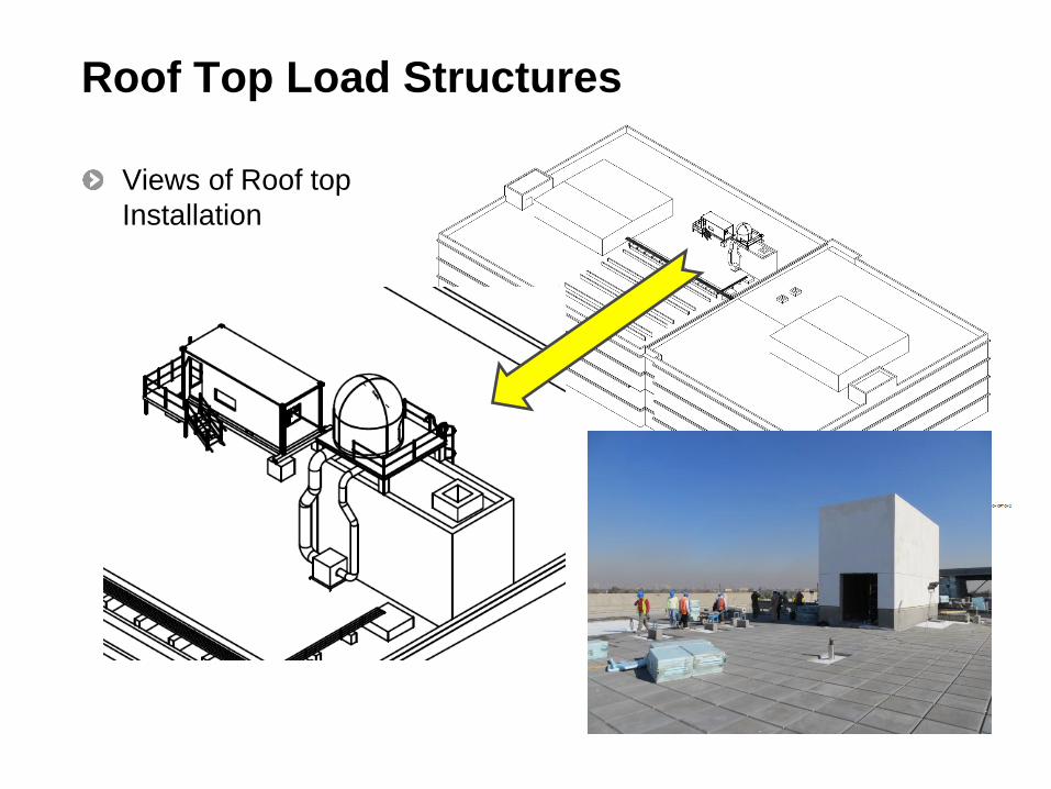
Roof Top Load Structures
Views of Roof top
Installation

Container Assembly Exterior ViewMain Components Identified.
Power, Signal
and Waveguide
Output
Opening and
Support for
Supplemental
A/C unit
Opening for
Power Input
Panel
2 access doors

Detailed Design Considerations
High Ambient air temperatures in summer seasons with the
seasonal high average of 44°C.
Maximum solar loading in the region of over 500 watts/m2.
Electro-Magnetic Interference (EMI) design requirements.
High reliability and availability are critical for protection.
Provide environmental shelter protection for critical electronic
equipment.

Initial Concept Design Issues and Challenges
When I was brought onto the design team and reviewed
the initial concept design I was able to recognize some key
short comings:
• The Initial sizing of the Air Conditioning Unit did not include the
environmental thermal loading and that the AC unit being a long lead
item was already ordered was undersized.
• The need for service personnel to have adequate ventilation of “fresh
air” was overlooked.
• The EMI requirement was challenged because of the through wall
piercings for the AC unit refrigerant lines to the evaporator resulted in
a area of EMI ingress/egress.

Design Changes to Overcome the
Issues and Challenges.
I addressed the EMI Ingress/Egress concern by bringing the Compressor
and Condenser package into the EMI “Envelope” by using EMI “Honey
Comb” filters that would provide the needed shielding and still allow for
the air flow required by the condenser fan.
I added a ventilation system that was capable of providing the needed
fresh air as determined by OSHA requirements for two service personnel.
This system was controlled by dampers and a fan that would be turned
on with the inside illumination when service personnel entered the
container and go off and close when the personnel left and turned off the
lights.
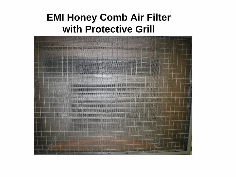
EMI Honey Comb Air Filter
with Protective Grill

Design Changes to Overcome the
Cooling Issues and Challenges.
I validated my suspected claim that the current two
packaged AC unit was not capable to cool the container by
using a “Back of the Envelope” hand calculation using the
ACCA Manual J worksheet.
Determined that a “supplemental AC unit was required.
The supplemental AC unit was “oversized” to allow for high
temperature operation degradation and to provide design
margin for reliability.

“Back of the Envelope Calculation”
Heat Loads
Component
Heat Emission to the
Containerized system
Cooling Air (kW)
Heat Emission to the
Containerized system
Cooling Air (BTU/Hr)
Climate System
Air Handler (FAU) 1.30 4435.8
Sensor
TRU + Stand by 4.15 14160.4
SDU 0.70 2388.5
Two Lap Tops 0.10 341.2
RIU 0.05 170.6
TT 0.17 580.1
28 VDC
Timeserver 0.06 218.4
IFF Interrogator 0.03 102.4
IFF Booster 0.05 170.6
Power Loss DC Conversion 0.20 682.4
Miscellaneous
DAU 0.30 1023.6
Battery Charger 0.20 682.4
Power Distribution 0.20 682.4
One Person 0.09 300.0
Environmental Heat Gain 4.02 13716.8
Totals 11.62 39655.7
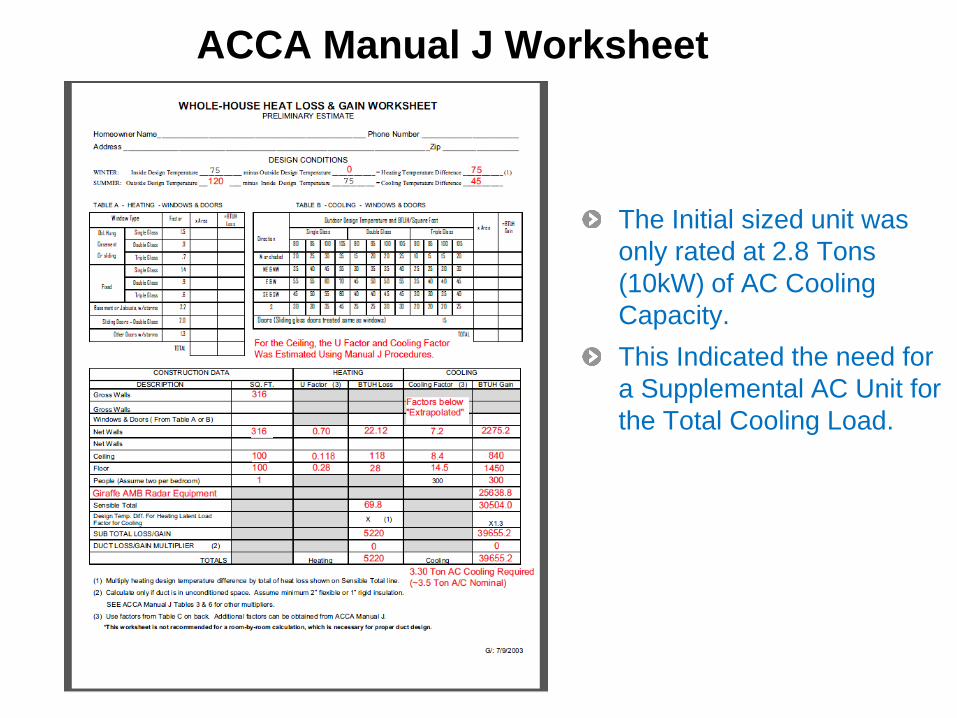
ACCA Manual J Worksheet
The Initial sized unit was
only rated at 2.8 Tons
(10kW) of AC Cooling
Capacity.
This Indicated the need for
a Supplemental AC Unit for
the Total Cooling Load.

Block Diagram of AC Cooling of
Container Equipment
TRU SDU
Air Flow
Air F
low
Air F
low
Air Flow to “Room” Air Flow
Air Handler
(Blower)
Room
Air Filter
Evaporator UnitHVAC
Condensor
Unit
“Supplemental”
AC Unit
“Supplemental” AC Unit
Recirculation of “Room”
Air During Operation
Air
Flo
w in
fro
m “
Ro
om
”

Container AC Unit Placement and Wall Insulation

Container Details

Cooling Units and Container Insulation Values
Subcomponent Description Cooling Capacity
Weiss ZKB 15/10-SH Main Air Conditioning Unit (Split Pack) 2.8 Tons (10 kW)
Friedrich Hazardgard SH20 Supplemental Air Conditioning Unit (window unit)
1.6 Tons (5.7 kW)
Owens Corning Foamular 150 Extruded Polystyrene Rigid Foam Insulation
Rigid Foam Insulation utilized in walls and ceiling of container
R-5 per inch

Container Cooling Issue
When the system was deployed
we quickly identified a cooling air
distribution issue!
• Air circulation within the container is
not sufficient to get the cool air to
where it is needed most!
• The Container had a “cool” end and a
“hot” end!
• The cool air circulates at one end of
the container, while the warm air
circulates at the other end!• Resulting in SDU temperature warnings
and faults!
“Before” illustration of heat flow

Container Cooling Air Distribution
Solutions
Created a computer simulation model to investigate the
potential solution of adding air flow directing duct work
tothe Transmitter Unit (TRU) and the Signal Data Unit
(SDU).
Needed to validate that there indeed was sufficient air
conditioning capacity.
Needed to show system would operate in the extreme
“hot” environmental conditions and eliminate SDU over
temperature warnings and faults.

Container Modeling
The container was modeled and represented by a 0.089
thick steel shell, with 3 inches thick foam insulation of (R-
5/inch) along the exterior walls and 1/8 inch wood paneling
with the foyer room having only 1 inch thickness between
the adjacent wall of the equipment room. The floor was
represented by a steel plate with a 1/8 inch surface that
was left “un-insulated”.
The heat loads were assigned to representative models for
the equipment and assigned the values from Table on
Slide 13.
The thermal loads for the SDU and TRU were modeled
using the thermal dissipative power assigned to a low flow
resistance porous media representation; airflow through
these devices was modeled using constant flow fan
representations.

Container Modeling - Continued
The air handler thermal contribution was handled again
with the porous media representation with the associate
thermal load assigned. Airflow through the air handler was
accomplished by modeling the connecting ductwork.
To realize results of the air intact of the air handler a
porous media grill was created at the entrance opening to
allow for the results of the surface parameters within the
software output.
The airflow for the SDU was fixed at 147 CFM and the flow
rate through the TRU rep was set to 500 CFM.
The main air condition and the supplemental air
conditioners were modeled again using a porous media
with the assigned cooling capacity as a negative power in
total watts and the airflow through each assigned using
“fixed flow” fan models.

Container Modeling - Continued
Air Conditioning Unit Modeling
• The main AC is a Weiss model number ZKB 15/10-SH with a cooling
capacity of 10,000 watts and supply air flow of 1,900 m3/hr (~1120
CFM).
• The supplemental AC a Friedrich Hazardgard 20 with 19500 BTU/hr
or approximately 5714 watts. (1 BTU/hr ≈ 0.293 watts). This modeled
unit representation was assigned a cooling capacity of 5700 watts
with supply airflow of 425 CFM.
• The air flow rates were derived directly from the specification sheet
for each of the AC units.

Container Modeling - Continued
Environmental Boundary Conditions - container were that
all external surface were assigned a constant temperature
of 44 °C with the exception of the top surface that was
assigned a power of 501 w/m2 surface generation power.
This value was obtained from an online academic
reference titled “Estimation of Global Solar Radiation
on Horizontal Surface Using Routine Meteorological
Measurements for Different Cities in Iraq” the location
of this on the web is:
http://scialert.net/fulltext/?doi=ajsr.2010.240.248&org=11

Container Modeling - Continued
Environmental Boundary Conditions - In the reference
document, “Estimation of Global Solar Radiation on
Horizontal Surface Using Routine Meteorological
Measurements for Different Cities in Iraq”, indicated
that the peak monthly daily solar radiation occurs in the
month of June with a value of 27.036 M J/m2/day or about
313 w/m2 for this location. In the real world, the daily
temperatures along with the solar radiation values are
transient values.
MODELING ASSUMPTION-By using the geographical
maximum value of 501 w/m2 value and assuming full
absorption with a maximum outside temperature of 44 °C
as a steady state condition, this should result in a worst-
case approximation and be very conservative by over
estimating the internal air temperatures.

Container Modeling - Continued
The porous media model
was used to represented
the heat load of each
device.
The air handler model
used the porous media at
the inlet to simulate air
intake filter and to obtain
modeling results, and at
the duct entrance for the
thermal load.
Air Handler
TRU
SDU
Porous Media
Thermal Load
Porous Media
Thermal Load
Porous
Media
Intake Air

Container Modeling - Continued
The remaining heat
producing equipment
was modeled and
placed in the proper
position within the
container.
The associated heat
loads were also
applied to the
equipment models.

Container Modeling - Continued
The main AC and
supplemental unit were
modeled using porous
media with a negative
heat load, with the air flow
assigned to each model
rep with “fixed flow” fans
as determined by the unit
specification sheet.
Main AC Unit Evaporator
Supplemental AC Unit

Container Modeling - Continued
The container model
included the materials of
construction in layers that
were modeled a solids.
This gives more accurate
through wall heat transfer
but has a cost of
processor time and
memory.
Solar loading was applied
as a distributive heat load
over the top surface area.
The remaining outside
walls of the container were
assigned the
environmental
temperature boundary
condition.

Simulation Results
This “worst case” simulation resulted in an average air inlet
temperature of the modeled air handler of 14 °C with a
minimum temperature of 12 °C, and a maximum inlet
temperature of 19.1 °C, within required limit of 20 °C.
The average air temperature including the un-cooled and
un-insulated foyer volume was 22.7 °C.
There was no “mixing fan” in this simulation and the air
mixing was all due to the modeled fans in the AC units and
those modeled fans within the forced air-cooled path with
the directing exit air ducts.
PAGE 30

Simulation Results - Continued

Simulation Results - Continued

Simulation Results - Continued

Simulation Results - Continued
The top surface temperature gradients are due to the distributed “solar load” of 500
w/m2 and note that surface temperature peaks to approximately 215 °C.
This does not include any convection or radiation heat loss to the environment and is
very conservative.
Steady state condition is the sun is beating down onto roof continually, in the real world
this is a transient condition.

Prototyped Modifications to Validate Simulation
1) TRU Exhaust Ducting• Directs warm exhaust air down and away from the blower
inlet
• THIS IS THE MOST IMPORTANT MODIFICATION
2) SDU Exhaust Ducting• Directs warm exhaust air down and away from the blower
inlet and away from the TRU
• ANTHER IMPORTANT MODIFICATION
3) Circulating Fan (Added as an Enhancement)• Directs cool air from the a/c system directly towards the
blower air inlet
• Creates circulation
• Study shows this is really not needed, but was added to increase air “mixing”.

Verified Effectiveness of Cooling Fix on Site
Once cooling modifications were in place on the typical summer day of 38 °C at high sun.• Set thermostat in room at 20 C
• Turned off secondary AC
• Allow room temperature to stabilize
• Door closed
• Preferably lights off so outside air is not circulating through container (outside air ventilation system off).
• Measure temperature of cooling air with IR thermometer (or equivalent)
• Was approximately 20 C (66F) entering blower
• SDU/TRU air duct will also measure approximately 20 C (66 F)
Secondary AC will be on and used to supplement cooling in the extreme hot ambient temperatures of 44 °C plus and with added heat load due to incident solar radiation.

Questions?
I know I did not speak to any of these Topics.
But in the air conditioner world what is meant by “Sensible Heat”?
What is the difference between the total cooling capacity and the
sensible heat load.
What does “Dew Point” mean in the air conditioner world, and what
issues does it present?
What are the variables that determine the operating temperature range
of an air conditioning unit?
What causes the cooling performance degradation with temperature?

My contact information
Peter J. Ruzicka
Senior Mechanical Engineer
Sensor Systems
Saab Defense and Security USA, LLC
5717 Enterprise Parkway
East Syracuse, New York 13057
Phone: (315) 234-7950, Fax: (315) 234-9400
Email: [email protected]