Convincing worldwide: HERMETIC pumps in solar thermal ...
16
CHEMICAL OIL & GAS REFRIGERATION POWER GENERATION SERVICE Convincing worldwide: HERMETIC pumps in solar thermal applications
Transcript of Convincing worldwide: HERMETIC pumps in solar thermal ...

C H E M I C A L
O I L & G A s
R E F R I G E R A T I O N
P O w E R G E N E R A T I O N
s E R v I C E
Convincing worldwide: HERMETIC pumps in solar thermal applications

2 H e r m e t i c
The technical power potential of solar thermal power
generation is much higher than worldwide power
consumption.
Newest generations of solar thermal power plants
are able to produce energy in the range from 50 to
250 megawatt, and thus they are most appropriate for
the industrial generation of low-cost current. When
integrating a thermal storage, the current additionally
can be planned and supplied reliably after sunset.
Solar thermal power plants have the potential to
reduce the dependence on fossil resources considerably
and to replace traditionally heated power plants.
They are concentrated on climate compatibility,
sustainability of power supply and security of supply.
Solar energy nearly is inexhaustible:
Every year, the sun sends 1.080.000.000 terawatt-
hours energy to the earth – the 60.000-fold of
world’s power requirement.
C L E A R s I G H T A N D
R E s P O N s I B I L I T Y
H e r m e t i c 3
The suitable solution for forward-looking technologies.
In solar thermal power plants
(CSP = Concentrating Solar Power),
canned motor pumps preferably are
used in the field of high temperature
applications.
While in parabolic trough power
plants and Fresnel collector plants
with heat transfer oil intermediate
circuit synthetic thermal oil is circu -
lated with a temperature of up to
400 °C, water is used as heat transfer
medium in solar thermal power
plants with direct evaporation
(DISS = Direct Solar System).
The different designs of solar thermal
power plants are based on sophisti-
cated and complicated processes.
High pumping fluid temperatures,
high system pressures and changing
rated flows determine the profile
of pump requirements and can be
implemented according to demand
by the use of canned motor pumps.
HERMETIC pumps provide solutions for special requirements.
Your power generation is based on: Our solution:
high availability We provide you with a reliable and nearlymaintenance-free pump technology tosafe and optimize various processes.
environment protection andoperational safety
The leakage-free pump technologyensures a safe conveying of different circuit fluids.
complex plant conditions Simple constructions allow safe operatingmethods and minimize the complexity.Thus, it can be reached more processsafety.
various applications We can put a wide range of pumps at your disposal for standardized applications as well as for customized processes.
HERMETIC pumps provide solutions
for special requirements.

4 H e r m e t i c
HERMETIC pumps are made fit
to your process conditions and
requirements. They became
integrated into your system as
a significant component of your
power plant. The only thing
that counts is: Availability at
maximum safety.
I N N O v A T I O N A N D
E X P E R I E N C E
The products of the company HERMETIC-
Pumpen GmbH stand for best quality
and maximum operational safety in
the chemical and petrochemical
industry, as well as in refrigeration
and power generation.
HERMETIC engineers combine selected
materials suitable for process and
individual solutions to sophisticated
units. Products are developed in
partnership with our customers in a
flexible construction and production
process coming up to the special
process requirements.
Long service lives and low life-cycle
costs are a main characteristic
of HERMETIC products from the
beginning.
An integral part of our developments
are the requirements for explosion
protection according to the directive
94/9/EC (ATEX).
The complete production line of
HERMETIC-Pumpen GmbH is an
essential contribution in observing
the directive 96/61/EC, the so-called
IPPC directive (Integrated Pollution
Prevention and Control), respectively.
HERMETIC pumps are “Best Available
Technology” when handling dangerous
and harmful fluids.

H e r m e t i c 5
For others it is “extreme”,
for us it is standard■■ changing pumping fluid tempe-
ratures■■ high system pressures up to
120 MPa■■ explosive and flammable fluids
High potential risk originating
from the medium to be conveyed
The fluid to be conveyed can have a
high or very high risk potential and
thus could be dangerous for human
being and environment. An absolute
tightness of the pumps must be
guaranteed.
we offer a highest level of safety –also with extreme parameters.
HERMETIC pumps are designed for
extreme conditions.
Thus, they always are used if conven-
tional technologies come to their
limit.
High system pressures, strong
temperature fluctuations, most
difficult pumping liquids – HERMETIC
pumps won’t be impressed by that.
But they convince with impressive
performance!
Fluids to be conveyed at extreme
temperatures
In the different technologies of solar
heat, extremely high temperatures can
be found making additional demands
on safety and availability of the pumps.
HERMETIC pumps are in a position
to convey liquids with a temperature
of up to +450 °C.
6 H e r m e t i c
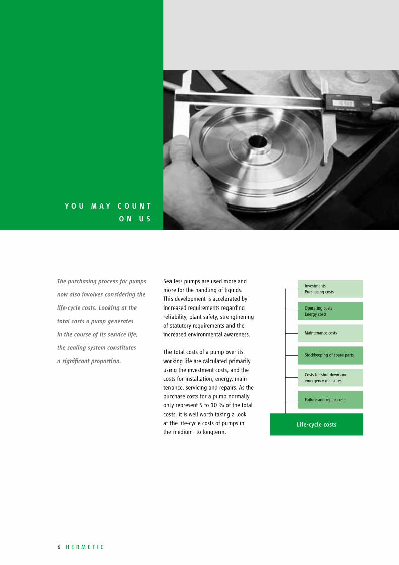
The purchasing process for pumps
now also involves considering the
life-cycle costs. Looking at the
total costs a pump generates
in the course of its service life,
the sealing system constitutes
a significant proportion.
Sealless pumps are used more and
more for the handling of liquids.
This development is accelerated by
increased requirements regarding
reliability, plant safety, strengthening
of statutory requirements and the
increased environmental awareness.
The total costs of a pump over its
working life are calculated primarily
using the investment costs, and the
costs for installation, energy, main-
tenance, servicing and repairs. As the
purchase costs for a pump normally
only represent 5 to 10 % of the total
costs, it is well worth taking a look
at the life-cycle costs of pumps in
the medium- to longterm.
Y O U M A Y C O U N T
O N U s
InvestmentsPurchasing costs
Life-cycle costs
Operating costsEnergy costs
Maintenance costs
Stockkeeping of spare parts
Costs for shut down andemergency measures
Failure and repair costs
H e r m e t i c 7
Depending on the operator’s point
of view, the results are by their very
nature variable, but they all indicate
that considering the investment costs
alone is not enough in the long-term.
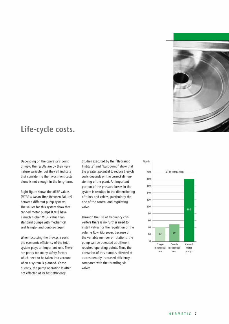
Right figure shows the MTBF values
(MTBF = Mean Time Between Failure)
between different pump systems.
The values for this system show that
canned motor pumps (CMP) have
a much higher MTBF value than
standard pumps with mechanical
seal (single- and double-stage).
When focussing the life-cycle costs
the economic efficiency of the total
system plays an important role. There
are partly too many safety factors
which need to be taken into account
when a system is planned. Conse-
quently, the pump operation is often
not effected at its best efficiency.
Studies executed by the “Hydraulic
Institute” and “Europump” show that
the greatest potential to reduce lifecycle
costs depends on the correct dimen-
sioning of the plant. An important
portion of the pressure losses in the
system is resulted in the dimensioning
of tubes and valves, particularly the
one of the control and regulating
valve.
Through the use of frequency con-
verters there is no further need to
install valves for the regulation of the
volume flow. Moreover, because of
the variable number of rotations, the
pump can be operated at different
required operating points. Thus, the
operation of this pump is effected at
a considerably increased efficiency,
compared with the throttling via
valves.
Life-cycle costs.
Months
200
180
160
140
120
100
80
60
40
20
0Single
mechanicalseal
Doublemechanical
seal
Cannedmotorpumps
42 50
180
MTBF comparison
8 H e r m e t i c
H E R M E T I C P U M P s
I N s O L A R T H E R M A L
P O w E R P L A N T s
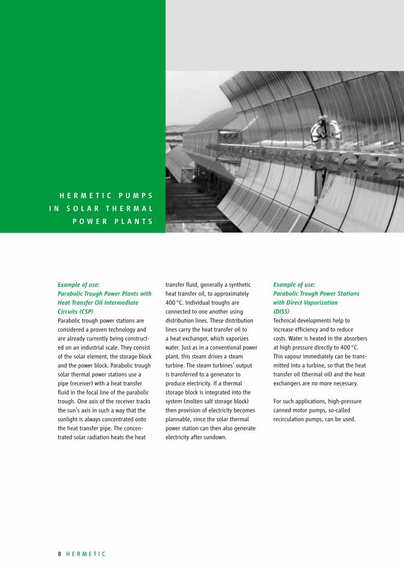
Example of use:
Parabolic Trough Power Plants with
Heat Transfer Oil Intermediate
Circuits (CSP)
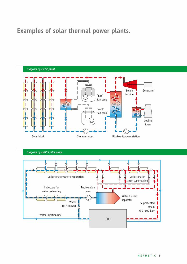
Parabolic trough power stations are
considered a proven technology and
are already currently being construct-
ed on an industrial scale. They consist
of the solar element, the storage block
and the power block. Parabolic trough
solar thermal power stations use a
pipe (receiver) with a heat transfer
fluid in the focal line of the parabolic
trough. One axis of the receiver tracks
the sun‘s axis in such a way that the
sunlight is always concentrated onto
the heat transfer pipe. The concen-
trated solar radiation heats the heat
transfer fluid, generally a synthetic
heat transfer oil, to approximately
400 °C. Individual troughs are
connected to one another using
distribution lines. These distribution
lines carry the heat transfer oil to
a heat exchanger, which vaporizes
water. Just as in a conventional power
plant, this steam drives a steam
turbine. The steam turbines’ output
is transferred to a generator to
produce electricity. If a thermal
storage block is integrated into the
system (molten salt storage block)
then provision of electricity becomes
plannable, since the solar thermal
power station can then also generate
electricity after sundown.
Example of use:
Parabolic Trough Power Stations
with Direct Vaporization
(DISS)
Technical developments help to
increase efficiency and to reduce
costs. Water is heated in the absorbers
at high pressure directly to 400 °C.
This vapour immediately can be trans-
mitted into a turbine, so that the heat
transfer oil (thermal oil) and the heat
exchangers are no more necessary.
For such applications, high-pressure
canned motor pumps, so-called
recirculation pumps, can be used.
H e r m e t i c 9
Diagram of a CSP plant
Diagram of a DISS pilot plant
Examples of solar thermal power plants.
Solar block Storage system
Coolingtower
GeneratorSteam turbine
Recirculationpump
Block-unit power station
Collectors forsteam superheating
Collectors forwater preheating
B.O.P.Water injection line
Collectors for water evaporation
“hot”Salt tank
“cool”Salt tank
Water / steamseparator
Superheatedsteam
(30–100 bar)
Water(40–108 bar)
10 H e r m e t i c
Hence the canned motor pump
contributes to a great extent to an
optimisation of process costs as well
as to the fulfilment of international
environment protection requirements.
The advantages of the canned motor
pump can be summarized as follows:■■ 100% leakage-free thanks to
double containment design.■■ Canned motor pumps comply with
the most significant requirements
regarding environmental protection.■■ Extremely low noise level.■■ Virtual lack of wear and minimized
maintenance.■■ High availability and long service
life.
■■ Due to the sealless construction and
the fluid-lubricated, hydrodynamic
slide bearings, an expensive and
complex installation of lubricating
and cooling systems is not neces-
sary.■■ Due to construction of the canned
motor pump, cost-intensive wearing
parts such as mechanical shaft seals,
buffer fluid systems or ball bearings
do not apply. As a consequence 3-
to 4-fold MTBF values (Mean Time
Between Failure) can be reached.
Reduced maintenance costs and
long lifetimes are the result. ■■ Easy installation, since no shaft
alignment of motor and coupling
is required.
One critical item when using
conventional centrifugal pumps is
to seal the shaft passages on the
pump casing. The high rate of
repairs is a reason for the steadily
increasing use of sealless pumps.
The canned motor pump is not
equipped with shaft seals which are
susceptible to faults or with ball
bearings sensitive to wear. Thus longer
lifetimes can be reached. Fewer
repairs with expensive spare parts
additionally offer considerable
reduction of life-cycle costs.
T E C H N O L O G Y
A T T H E H I G H E s T
s T A G E

H e r m e t i c 11
Pump principle of cannedmotor pumps.
Functional principle of canned
motor pumps
Canned motor pumps are character-
ized by a compact, integrated unit
without mechanical seal. The motor
and pump form a unit with the rotor
and the impeller fitted onto a common
shaft. The rotor is guided by two
identical, medium-lubricated slide
bearings. The stator on the drive
motor is separated from the rotor
space using a thin stator liner. The
rotor cavity itself, along with the
hydraulic section of the pump, creates
a combined cavity which needs to be
filled with pumping medium before
commissioning. The heat loss from
the motor is carried off by a partial
flow between the rotor and the stator.
At the same time, the partial flow
lubricates both slide bearings in the
rotor cavity.
Both, the can which is a hermetically
sealed component, and the motor
casing are used as a safety contain-
ment. Because of that, canned motor
pumps always ensure a highest safety
level when conveying dangerous,
toxic, explosive and valuable media.
impeller discharge nozzle rotor stator motor casing (secondary containment)
suction nozzles slide bearings rotor lining (primary containment)
impeller discharge nozzle rotor stator motor casing (secondary containment)
suction nozzles slide bearings rotor lining (primary containment)
Diagram of a single-stage canned motor pump
Diagram of a multistage canned motor pump
12 H e r m e t i c
C O N s T R U C T I O N
P R I N C I P L E s F O R
H I G H - T E M P E R A T U R E
A P P L I C A T I O N s
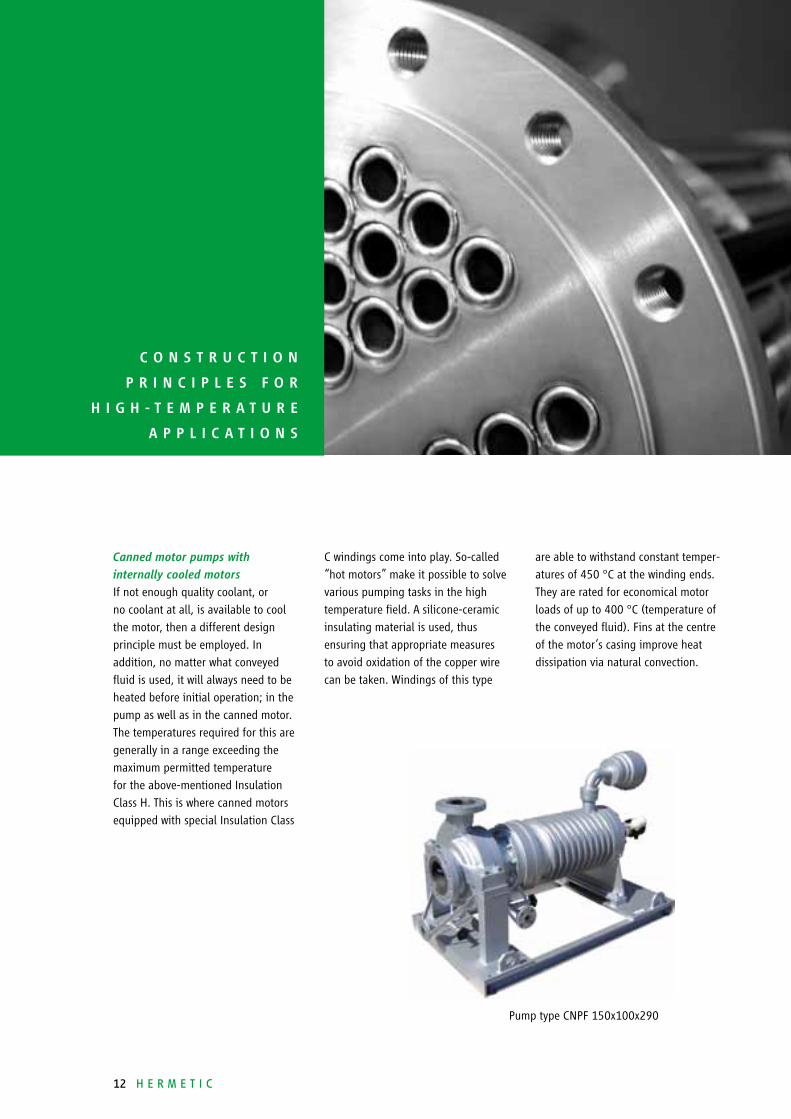
Canned motor pumps with
internally cooled motors
If not enough quality coolant, or
no coolant at all, is available to cool
the motor, then a different design
principle must be employed. In
addition, no matter what conveyed
fluid is used, it will always need to be
heated before initial operation; in the
pump as well as in the canned motor.
The temperatures required for this are
generally in a range exceeding the
maximum permitted temperature
for the above-mentioned Insulation
Class H. This is where canned motors
equipped with special Insulation Class
C windings come into play. So-called
“hot motors” make it possible to solve
various pumping tasks in the high
temperature field. A silicone-ceramic
insulating material is used, thus
ensuring that appropriate measures
to avoid oxidation of the copper wire
can be taken. Windings of this type
are able to withstand constant temper-
atures of 450 °C at the winding ends.
They are rated for economical motor
loads of up to 400 °C (temperature of
the conveyed fluid). Fins at the centre
of the motor‘s casing improve heat
dissipation via natural convection.
Pump type CNPF 150x100x290

H e r m e t i c 13
Canned motor pumps with
externally cooled motors
In this design, the pump is spatially
separated from the canned motor by
an intermediate component acting as
a thermal barrier. This prevents heat
transfer from the conveyed fluid to
the motor. A relatively narrow, long
circumferential gap equalizes the
pressure differential between the
hydraulics and the rotor cavity. An
auxiliary impeller is installed in the
motor itself, recirculating the fluid
in the rotor cavity through a heat
exchanger mounted around the motor
or a separately mounted external
heat exchanger. Motor heat loss is
absorbed by a cooling fluid. This
creates two pump circuits with different
temperatures. The operational circuit
can be rated at temperatures of up to
450 °C, while the conveyed fluid in
the secondary cooling / lubricating
circuit has much lower temperatures of
between 60 °C and 80 °C. As a result,
the motor windings can be manufac-
tured in long-lived Insulation Class H.
Due to the pressure equalization in the
thermal barrier‘s circumferential gap,
there is hardly any fluid exchange
between the two temperature levels.
This cooling option and/or alignment
can be used for single and multistage
canned motor pumps.
Should no cooling water be available,
then various models of air heat
exchanger can also be used. These
include simple honeycomb heat
exchangers with ventilators, mounted
above the unit and fixed to the base
plate. Separately installed system dry
air heat exchangers (also with axial
ventilators) are used for higher pump
ratings.
Pump type CNPK 100x50x400 Pump type CNPK 250-630
14 H e r m e t i c
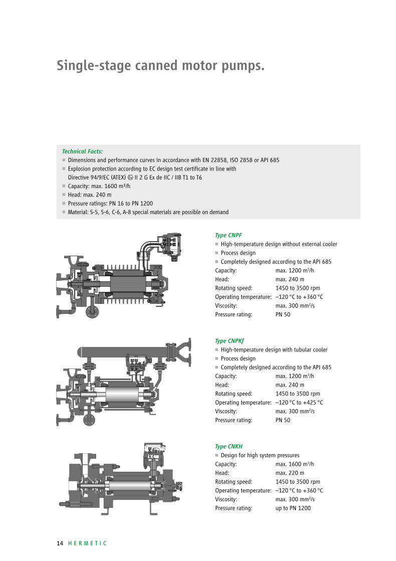
single-stage canned motor pumps.
Type CNPF■ High-temperature design without external cooler■ Process design■ Completely designed according to the API 685
Capacity: max. 1200 m3/h
Head: max. 240 m
Rotating speed: 1450 to 3500 rpm
Operating temperature: –120 °C to +360 °C
Viscosity: max. 300 mm2/s
Pressure rating: PN 50
Type CNPKf■ High-temperature design with tubular cooler■ Process design■ Completely designed according to the API 685
Capacity: max. 1200 m3/h
Head: max. 240 m
Rotating speed: 1450 to 3500 rpm
Operating temperature: –120 °C to +425 °C
Viscosity: max. 300 mm2/s
Pressure rating: PN 50
Type CNKH■ Design for high system pressures
Capacity: max. 1600 m3/h
Head: max. 220 m
Rotating speed: 1450 to 3500 rpm
Operating temperature: –120 °C to +360 °C
Viscosity: max. 300 mm2/s
Pressure rating: up to PN 1200
Technical Facts:■■ Dimensions and performance curves in accordance with EN 22858, ISO 2858 or API 685■■ Explosion protection according to EC design test certificate in line with Directive 94/9/EC (ATEX) II 2 G Ex de IIC / IIB T1 to T6
■■ Capacity: max. 1600 m³/h■■ Head: max. 240 m■■ Pressure ratings: PN 16 to PN 1200■■ Material: S-5, S-6, C-6, A-8 special materials are possible on demand
H e r m e t i c 15
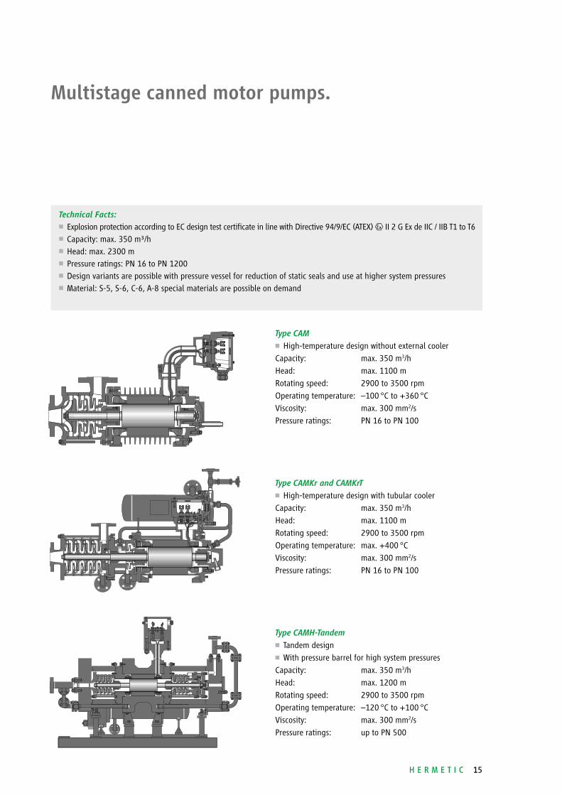
Multistage canned motor pumps.
Type CAM■ High-temperature design without external cooler
Capacity: max. 350 m3/h
Head: max. 1100 m
Rotating speed: 2900 to 3500 rpm
Operating temperature: –100 °C to +360 °C
Viscosity: max. 300 mm2/s
Pressure ratings: PN 16 to PN 100
Type CAMKr and CAMKrT■ High-temperature design with tubular cooler
Capacity: max. 350 m3/h
Head: max. 1100 m
Rotating speed: 2900 to 3500 rpm
Operating temperature: max. +400 °C
Viscosity: max. 300 mm2/s
Pressure ratings: PN 16 to PN 100
Type CAMH-Tandem■ Tandem design■ With pressure barrel for high system pressures
Capacity: max. 350 m3/h
Head: max. 1200 m
Rotating speed: 2900 to 3500 rpm
Operating temperature: –120 °C to +100 °C
Viscosity: max. 300 mm2/s
Pressure ratings: up to PN 500
Technical Facts: ■■ Explosion protection according to EC design test certificate in line with Directive 94/9/EC (ATEX) II 2 G Ex de IIC / IIB T1 to T6■■ Capacity: max. 350 m³/h■■ Head: max. 2300 m■■ Pressure ratings: PN 16 to PN 1200■■ Design variants are possible with pressure vessel for reduction of static seals and use at higher system pressures■■ Material: S-5, S-6, C-6, A-8 special materials are possible on demand
Among others, our products comply with:■■ Directive 2006/42/EC
(Machinery Directive)■■ Explosion protection acc. to
Directive 94/9/EC (ATEX); UL; KOSHA;
NEPSI; CQST; CSA; Rostechnadzor■■ Directive 96/61/EC (IPPC Directive)■■ Directive 1999/13/EC (VOC Directive)■■ TA-Luft■■ RCC-M, Niveau 1, 2, 3
HERMETIC-Pumpen GmbH is certified acc. to:■■ ISO 9001:2008■■ GOST; GOST “R”■■ Directive 94/9/EC■■ AD 2000 HP 0; Directive 97/23/EC■■ DIN EN ISO 3834-2■■ KTA 1401; AVS D 100 / 50;
IAEA 50-C-Q■■ Certified company acc. to § 19 I WH
Important features are readiness, mobility, flexibility, availability and reliability.
We are anxious to ensure a pump operation at best availability and efficiency
to our customers.
Convincing service.
Installation and commissioning■ service effected on site by own
service technicians
Spare part servicing■ prompt and longstanding
availability■ customized assistance in spare
part stockkeeping
Repair and overhauling■ professional repairs including test
run executed by the parent factory■ or executed by one of our service
stations worldwide
Retrofit■ retrofit of your centrifugal pumps
by installing a canned motor
to comply with the requirements
of the IPPC Directive
Maintenance and service
agreement■ concepts individually worked
out to increase the availability
of your production facilities
Training and workshops■ extra qualification of your
staff to ensure the course of
your manufacture
ENERGIE / E / 01 / 2012
All details as stated in this document comply with the technical standard that is applicable at the date of printing. These details are subject to technical innovations and modifications at any time.
HERMETIC-Pumpen GmbHGewerbestrasse 51 · D-79194 Gundelfingenphone +49 761 5830-0 · fax +49 761 [email protected]
Images at page 5/8: Solar Millennium AG