Conveyor Mounted Radiation System Work Plan
103
Conveyor Mounted Radiation System Work Plan Thorium Remediation Project Tulsa, Oklahoma April 2004 Prepared by: Shonka Research Associates, Inc. For: Rtem~dhaI Constrauotion Serviftso LP. 9720 Derrington Houston, Texas 77064 (281) 955-2442 JK (B ill)uminum&C i o t Kaiser Alumninum & Chemical Corporation. Date: Revision 00 Effective Date Apffl 2004
Transcript of Conveyor Mounted Radiation System Work Plan

Conveyor Mounted Radiation SystemWork Plan
Thorium Remediation ProjectTulsa, Oklahoma
April 2004
Prepared by:
Shonka Research Associates, Inc.
For:
Rtem~dhaI Constrauotion Serviftso LP.
9720 Derrington
Houston, Texas 77064
(281) 955-2442
JK (B ill)uminum&C i o tKaiser Alumninum & Chemical Corporation.
Date:
Revision 00Effective Date Apffl 2004

P, -.,Z 7 '7
Conveyor Mounted Radiation SystemWork Plan
Thorium Remediation ProjectTulsa, Oklahoma
April 2004
Prepared by:
Shonka Research Associates, Inc.
For:
9720 Derrington
Houston, Texas 77064
(281) 955-2442pSt inSO I
Diana .- rown Da:Remedial Constructions Services, L.P.
Richard t. rewis 'Date:Remedial Construction Services, L.P.
I
Revision 00Effective Date April 2004
al1

Thorium Remediation Project - Tulsa, OKConveyor Mounted Radiation System Work Plan
Revision 0TABLE OF CONTENTS
1. PREFACE ................. 1
2. BACKGROUND ................. 1
3. INTRODUCTION ................ 1
4. METHODOLOGY ................... 2
4.1 THlE CONVEYOR MOUNTED SMCM .24.2 ESTABLISHMENT FOR SORTING UNITS .34.3 PRESORTING ACTIVITIES .34.4 PERFORMING THE SORTING .34.5 SORTING METHODS 4
4.5.1 On-Site (0-Pile) DCGLemc DiversionAlarms . ...............................54.5.2 Landfill (L-Pile) DCGLw Diversion Alarms . .................................S
4.6 QUALITY CONTROL ......................................... 54.7 DATA ANALYSIS ......................................... 6
4.7.1 RecordedDaa ........................................D..6
5. SORTING RESULTS ......................................... 7
5.1 SMCM VS. LAB ......................................... 7
6. MARK III CONTAMINATION MONITORS ....................................... 7
6.1 ACTIVITY MONITOR ......................................... 76.2 INSIWuBUCKETMONITOR ......................................... 8
7. RESPONSIBILITIES ...................................................................................................... 8
8. M OBILIZATION ........................................................................... 8
9. P ROC EDURES ......................................... 8
Table of Tables:
Table 5-1. Typical summary of laboratory radiological information collected ........................ 7
Attachment
Attachment 1 - Sorting Release Record Report
i

Thorium Remediation Project - Tulsa, OKConveyor Mounted Radiation System Work Plan
Revision 0Acronyms:
Acronym Descriptioncps Counts per Second
DCGLEMC Derived Concentration Guideline Level - Elevated Measurement ComparisonDCGLw Derived Concentration Guideline Level - Wilcoxon Rank Sum
DOE Department of EnergyDP Decommissioning Plan
Kaiser Kaiser Aluminum and Chemical CorporationMCA Multi-Channel AnalyzerNal Sodium Iodide
NASVD Noise Adjusted Single Value DecompositionNIST National Institute for Standards and TechnologyNRC Nuclear Regulatory CommissionRCT Radiological Control Technician
RECON Remedial Construction Services, L.P.SMW Standard Magnesium Corporation
SMCM Sub-Surface Multi-Spectral Contamination MonitorSRA Shonka Research Associates
ii

Thorium Remediation Project - Tulsa, OKConveyor Mounted Radiation System Work Plan
Revision 0
1. PREFACE
The Shonka Research Associates, Inc. (SRA) conveyor mounted radiation system workplan involves three items.
* Setup, operate and maintain a radiation system mounted over a conveyor.* Summarize the data collected from the radiation detection system mounted over
the conveyor for a paper report handed to Remedial Construction Services, L.P.(RECON).
* Setup, operate and maintain additional radiation detector systems used for wastecharacterization.
2. BACKGROUND
The Kaiser Aluminum & Chemical Corporation (Kaiser) plant in Tulsa, Oklahoma wasbuilt by the Standard Magnesium Corporation (SMC) in the early to mid-1950s tomanufacture magnesium products. Kaiser purchased the facility in 1964.
The Kaiser facility is located at 7311 East 41st Street in Tulsa, Oklahoma. It is situated inTulsa County, Oklahoma, about 5 miles southeast of the downtown center of the city ofTulsa. An approximate 14-acre pond parcel north of the railroad contains a retentionpond, the flux building, a former freshwater pond area, and a segment of Fulton Creek.The remediation area is bounded by the south fence line, the freshwater pondembankment on the west, Fulton Creek ditch on the north, the east fence line, and thenorthern and western edges of the flux building and paved area. The areas to beremediated include a portion of the 4-acre operational area south of the railroad, and alarge portion of the 14-acre pond parcel located north of the railroad. The pond parcel isdivided into three parts--the non-impacted former freshwater pond to the west 4 acres, theaffected retention pond/reserve pond area to the east approximately 9 acres, and the areacontaining the flux building and paved area approximately I acre.
3. INTRODUCTION
RECON will utilize a system of conveyors and radiation monitors to sort the soil anddross (material) and to document that the material is below the limits dictated in thefacility Decommissioning Plan (DP) filed with the Nuclear Regulatory Commission(NRC) and is ready for the Final Status Sampling (FSS) Survey. Radiationcharacterization tools will be utilized and include: walk-over monitors and excavatorbucket monitor. SRA was contracted to build and operate radiation monitors or systems.
SRA utilizes a system called the Subsurface Multi-spectral Contamination Monitor(SMCM), which was developed with funding from the NRC (NRC-04-92-096."Continued Development of a High Sensitivity Landfill Monitor: The Results of a PhaseII SBIR Grant". December, 1994). SMCM combines into one instrument the capabilitiesof both scanning (rolling) detection with in situ gamma spectrometry. The SMCM is ascanning spectrometer. The data is processed with Noise Adjusted Single ValueDecomposition (NASVD) algorithms originally developed for sonar. This treatment of
1

Thorium Remediation Project - Tulsa, OKConveyor Mounted Radiation System Work Plan
Revision 0
the data greatly reduces the statistical fluctuation normally encountered in scanningdetection.
The SMCM controls the operational flow of the material to sort the raw material into 2piles, On-Site Piles (0-Pile), < 31.1 pCilg of Th-232 net or Landfill Piles (L-Pile) 2 31.1pCi/g of Th-232 net. The established background level for the Thorium RemediationProject is 1.1 pCi/g. The SMCM sorting logic setpoint is 31.1 pCi/g of Th-232 net. Thesetpoint for the SMCM sorting logic may vary during the sorting operations if necessary.
The O-Piles will be used as onsite backfill. The L-Piles will be transported to USEcology Inc., Simco, Idaho (Waste Transfer Facility) with final disposal at US Ecology,Inc Grandview Operations Facility, Grandview, Idaho.
The SMCM system will be operated with alarm setpoints. The raw material flow iscontrolled by the RECON excavator operator. The SMCM will control diversion parts ofthe conveyor system.
4. METHODOLOGY
4.1 The Conveyor Mounted SMCM
The SMCM utilizes a radiation detection system that is a fixed platform mounted over aconveyor. The Thorium Remediation Project will make use of a single thallium-dopedsodium iodide (Nal (Tl)) detector. Spectra in a pre-defined energy range will becollected successively over a fixed time via a Multi-Channel Analyzer (MCA).
The detector will be placed into a protective enclosure. The detector will have thermalprotection for temperature stabilization and will be shielded to reduce the radiationbackground as well as reducing any variability from changes in background due to radonin air, moving vehicles, and changes in nearby material. A trailer will be used as amobile command center for the SMCM electronics and the process computer system.
Prior to deployment, the detector will be calibrated. Appropriate calculations will beperformed to establish a calibration in an equivalent manner to the method of Helfer andMiller: "Calibration factors for Ge Detectors used for Field Spectrometry (Health PhysicsVol. 55 No.1 (July), pp 15-29 1988).
The SMCM includes a sensor to verify that the conveyor speed is 250 fpm (feet perminute). The sensor is monitored (and the conveyor speed is calculated) during datacollection.
The SMCM is equipped with a level switch to verify the material depth.
All measurements will be recorded to the process computer's hard drive and backed upon a CD. The SMCM operator controls the starting and stopping of the recorded data.All the recorded data between the starting of the recorded data and stopping of the
2

Thorium Remediation Project - Tulsa, OKConveyor Mounted Radiation System Work Plan
Revision 0
recorded data is called a "survey strip." Data collected when the belt is stationary or withno material present is recorded but not reported.
The SMCM is equipped with a number of alarm enunciators. When material >31.1pCi/g of Th-232 net is detected, the operation screen changes color. A remote day lightreadable monitor is available for the conveyor operator. The SMCM process computeractivates a radiation diversion alarm light to the operator.
4.2 Establishment for Sorting Units
The raw material from the 9-acre pond parcel, the 3-acre area south of the railroad tracksand the area under the Flux Building define the excavation areas. The excavation areawill have a grid system as shown in RECON's Work Plan, Figure WP B 2, to define theorigin of materials.
4.3 Presorting Activities
Excavated material will be presorted prior to being separated by the Conveyor MountedSMCM. The presort will be a rough cut for the purpose of providing a relativelyconsistent feed to the Conveyor Mounted SMCM. Material presorted as above 31.1 pCi/gof Th-232 net will be fed to the conveyor system separately from material presorted asbelow that criterion. Campaigning above and below criterion material separately willprevent the sorter from cycling excessively during operation. The bucket monitordescribed in Section 6.2 will be used to perform the presort. Decisions on which materialwill need to be disposed of off site and which material is suitable for backfill will bebased on detailed data collected from the Conveyor Mounted SMCM as discussed inSection 4.4.
If the bucket monitor fails to perform as expected or becomes unavailable, hand-heldmeters or other methods will be used for the rough presort.
4.4 Performing the Sorting
RECON's excavator will place material on a vibrating screen to remove all debris andany material over 6 inches in diameter. The material that is less than 6 inches in diameterwill pass thru the vibrating screen and will be carried to the Conveyor Mounted SMCMconveyor. Before it passes under the Conveyor Mounted SMCM, material will be leveledwith a leveling bar placed across the conveyor to ensure that material is spread evenlyacross the conveyor belt and that only 6-8 inches of material will pass under theConveyor Mounted SMCM. Once material is found to be either < 31.1 pCi/g of Th-232net or 2 31:1 pCi/g of Th-232 net, it will fall into a pant leg chute. The SMCM sortinglogic setpoint is a derated value from 31.1 pCi/g of Th-232 net. The Conveyor MountedSMCM process computer will electronically control the gate inside the chute.Depending on the pCilg, the material will fall onto one of two stacker conveyors creatingan L-Pile or O-Pile described below.
3

Thorium Remediation Project - Tulsa, OKConveyor Mounted Radiation System Work Plan
Revision 0
Onsite Pile (0-Pile) - These raw materials will be sorted into piles of approximately 2000ton sorting units (sorting units may vary and should not be considered a change to theplan). Note.- The number of piles is based on the quantity of materials sorted with a valueof < 31.1 pCi/g of Th-232 net. Material < 31.1 pCi/g of Th-232 net will be placed inpiles with identification numbers such as; 0-1, 0-2, 0-3, etc. Note: "O" - representsOnsite Pile, "1" representing an incrementing number based on the number of pilesgenerated.
Landfill Pile (L-Pile) - These raw materials will then be sorted into piles of variousranges in pCi/g. Note: The number of piles and ranges selected to associate with thosepiles is based on the quantity of materials in various ranges of value of pCi/g in the L-Pilematerial. Material less than or equal to the derived concentration cut-off levels (ranges inpCi/g) will be placed in piles with naming conventions such as:
L-1-A 31.2pCi!g - 35 pCi/g of Th-232 netIL-l-B 3 5.1pCi/g - 45 pCi/g of Th-232 netIL-1-C 45.lpCi/g - 55 pCi/g of Th-232 netL-1-D 55.1 pCi/g- 100 pCi/g of Th-232 net
Note: "L" represents (L-Pile), "1" representing an incrementing number based on thenumber of L-Piles produced, and the "A", "B",- "Z", will represent the range of values ofTh-232 pCi/g present. Depending on the actual materials encountered, the number ofpiles and ranges of activities will vary throughout the project. With this data the processcomputer creates a standardized pick list that will be utilized to create approximate 100ton stockpiles <55 pCi/g for loading into railcars as described in Section 4.5.2. During thesorting for creating approximate 100 ton stockpiles, the pant leg chute will divert materialunder the direction of the SMCM computer if the stockpiled material will exceed 55pCi/g averaged over a total of 100 tons. Diverted materials will be resorted with materialsthat will meet the offsite acceptance criteria (<55pCi/g).
All materials that have been scanned and placed into 100-ton piles will have a unique pilename as discussed above. For O-Piles, a number of piles may be treated as a sorting unit.For L-Piles there is only one pile that is equal to the sorting unit. Each L-Pile sorting unitis summarized in a Sorting Release Record Report that will accompany manifests foroffsite material. Sorting release records will be generated upon request by the sitemanagement team members. A sample copy of the Sorting Release Record Report islocated in Attachment No. 1.
4.5 Sorting Methods
The conveyor mounted SMCM collects data over a fixed time period as the materialmoves at 250 fpm (feet per minute). The collected data is termed an acquisition. Duringeach acquisition, the process computer records the following: a spectra and live time fromthe MCA, the distance traveled, the average height of the material and the averagedensity. Periodically during the operation, the operator records the system statusinformation such as temperature in a field notebook or other means. Although all ofthese signals are collected and monitored during operations, the system's most important
4

Thorium Remediation Project - Tulsa, OKConveyor Mounted Radiation System Work Plan
Revision 0
function is the real time low-level radiation alarms based on the data analysis. A briefdescription of the real time data analysis, alarms, and investigative measures is givenbelow.
The spectra will be converted from units of counts to count per second (cps) by dividingby the live time. The net value in each region of interest is determined. The regions ofinterest of concern will be for potassium (K-40 @ 1461 keV), uranium (U-238 using Bi-214 @ 1764 keV), and thorium (Th-232 using TI-208 @ 2614 keV). The monitoring ofK-40 and U-238 helps assure the conveyor spectra is being recorded correctly whencomparisons are made with the off-site lab as discussed in Section 5.1. A Cs-137 densitygauge is used as described below. A source response check will be performed wheneverthe belt is empty.
The net Cs-137 is required for the density measurement and is calculated by removing thecontribution to the Cs-137 region of interest from each of the primordials: K-40, U-238,and Th-232. To strip a spectrum (window) means to remove the contributions to anenergy window from radionuclides emitting gammas of higher energies. Only a fractionof the emitted gamma photons register as full energy photons. Scattered photonsoriginating from higher energy photons are measured in lower energy windows. Thecontribution from those scattered photons is removed when stripping the spectra.
4.5.1 On-Site (0-Pile) DCGLemc Diversion Alarms
Alarm logic drives the sorting mechanism. A moving window that averages the materialon the conveyor belt will be set to divert material that is 2 31.1 pCi/g of Th-232 net.
4.5.2 Landfill (L-Pile) DCGLw Diversion Alarms
The conveyor will divert material if the average of a railcar will exceed 55 pCi/gaveraged over a total of 100 tons. A pick list (a list that contains the various pCi/g levelsin each L-Pile) will be provided for the heavy equipment loader operator so that the loadscan be fed in a manner that ensures the 55 pCi/g is not exceeded. For example,alternating loads of 45 and 65 pCi/g materials should average 55 pCi/g and no materialwill be diverted as long as the 45 pCi/g hopper load is used first to start the averagingprocess. As the total reaches the 1 00-ton railcar load, the influence on the average fromalternating higher range pCi/g materials and lower range pCi/g materials will diminish.
4.6 Quality Control
Quality control and quality assurance for the laboratory environment has been studied forsome time and is well established in the nuclear industry for radiation detectionequipment. However, quality control associated with the operation of radiation detectorin the field is not generally established with the same degree of rigor. To attain lab-likestability in the field, rigorous quality control and quality assurance measures are requiredthat go beyond common practice. The following text outlines the traditional qualitycontrol measures for gamma spectrometers when operated in a laboratory environment.The remaining controls that are imperative to proper field operation have been integratedinto Section 4.7.
5

Thorium Remediation Project - Tulsa, OKConveyor Mounted Radiation System Work Plan
Revision 0
Prior to deploying, the Nal detector will be calibrated at SRA's laboratory in Marietta,Georgia. The MCAs will be aligned to ensure a linear relationship, with a zero offset,between channels and energy. The internal computer-controlled digital gain in all MCAsis adjusted to align 1461 keV (K-40 photo peak) into channel 250. This calibration(5.844 keV per channel with 512 channels or 0 to 3 MeV) is used in order to resolve the2.614 keV photon from the Tl-208 daughter product in the Th-232 decay chain. Thedetector will be calibrated to determine, their intrinsic efficiency by placing NationalInstitute for Standards and Technology (NIST) traceable button sources, Co-60 (nominal0.5 jsCi) or Cs-137 (nominal 9.0 pCi), one meter below the front face of the detector.
During operation, source response checks will be performed at the beginning and end ofeach day and at least once during the day (typically every five hours throughout the day).The source response checks will be performed by recording data over a fixed time whilecheck sources are present. The sources will be mounted to a removable source responsecheck fixture, which is mounted to the detector enclosure. The sources used for thesource response checks are not typically NIST traceable. The sources are only intendedto act as a stable artifact and not as a means of calibration. The source response checksare the same checks performed with hand-held instruments. In the case of the SMCM,the source response checks serve as a measure of the condition of the detector, preamps,and MCAs. Quality control charts for the source response checks will be maintained foreach detector.
A density gauge will be used, and source response checks will be performed by theSMCM software whenever the belt is free of material.
4.7 Data Analysis
Implementation of a laboratory radiation detector in the field requires that added qualitycontrol / quality assurance measures be taken. Some of these added measures, as thestandard measures described above in section 4.6, can be taken, and evaluated beforeprocessing. However, the source of information for the majority of these measurescomes from the data itself. The measures can only be evaluated after processing. Thepost analysis and data processing are described below; collectively, the two arecommonly referred to as post processing.
4.7.1 Recorded Data
In order to achieve the needed detection limit and throughput, a large number ofparameters will be recorded and analyzed by the SMCM system. For each acquisition,the live time and raw spectra is recorded for the detector. During operation, a summa'ryfile is also generated which records virtually levery parameter that was collected orcalculated for each acquisition.
The NASVD algorithms will be performed during the post processing. NASVD is aspectral component analysis procedure for the removal of noise from gamma-ray spectra.The procedure transforms observed spectra into orthogonal spectral components. Thelower-order components represent the signal in the original observed spectra, and the
6
Thorium Remediation Project - Tulsa, OKConveyor Mounted Radiation System Work Plan
Revision 0
higher-order components represent uncorrelated noise. Noise is removed from the.observed spectra by rejecting noise components and reconstructing the spectra fromlower-order components. The raw spectra files will be loaded for a particular data set andthe NASVD software determines the principal components. Identification of pointsources is one of the tasks for which NASVD is very efficient.
5. SORTING RESULTS
Summary reports for each L-Pile and O-Pile will be documented on the form "SortingRelease Record" as shown in Attachment #1.
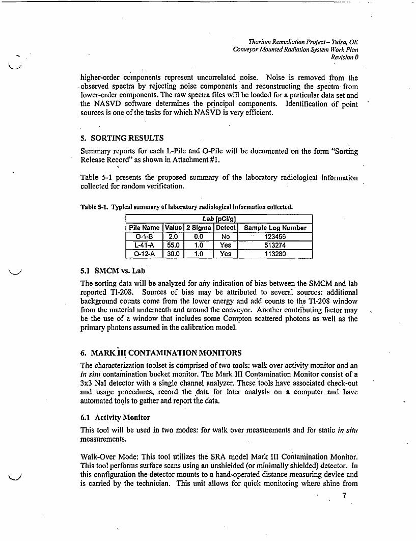
Table 5-1 presents the proposed summary of the laboratory radiological informationcollected for random verification.
Table 5-1. Typical summary of laboratory radiological Information collected.
Lab [pCi/g]Pile Name Value 2 Sigma Detect Sample Log Number
0-1-B 2.0 0.0 No 123456L-41-A 55.0 1.0 Yes 5132740-12-A 30.0 1.0 Yes 113280
5.1 SMCM vs. Lab
The sorting data will be analyzed for any indication of bias between the SMCM and labreported Tl-208. Sources of bias may be attributed to several sources: additionalbackground counts come from the lower energy and add counts to the TI-208 windowfrom the material underneath and around the conveyor. Another contributing factor maybe the use of a window that includes some Compton scattered photons as well as theprimary photons assumed in the calibration model.
6. MARK iII CONTAMINATION MONITORS
The characterization toolset is comprised of two tools: walk over activity monitor and anin situ contamination bucket monitor. The Mark III Contamination Monitor consist of a3x3 Nal detector with a single channel analyzer. These tools have associated check-outand usage procedures, record the data for later analysis on a computer and haveautomated tools to gather and report the data.
6.1 Activity Monitor
This tool will be used in two modes: for walk over measurements and for static in situmeasurements.
Walk-Over Mode: This tool utilizes the SRA model Mark III Contamination Monitor.This tool performs surface scans using an unshielded (or minimally shielded) detector. Inthis configuration the detector mounts to a hand-operated distance measuring device andis carried by the technician. This unit allows for quick monitoring where shine from
7

71orium Remediation Project - Tulsa, OKConveyor Mounted Radiation System Work Plan
Revision 0
nearby radiation sources is not of concern and where surface conditions are safe forworkers to enter. This tool can also be used to screen the 2-foot lifts during backfilloperations.
Static or Direct Push Mode: This tool utilizes the SRA model Mark III ContaminationMonitor. This tool performs a spot check of the raw material "drying pile" or other areasin the raw material pond. In this configuration the detector is pushed into the rawmaterial with raw material backfilled over the entire detector. This tool will be used inconjunction with the Walk-Over mode to subtract shine.
6.2 In Situ( Bucket Monitor
This tool utilizes the SRA model Mark III Contamination Monitor. This tool provides 3types of information: optimizes where to stop digging, allows the operator to identifylevels of Th-232 in the material being excavated, and gives a rough analysis of thematerial being placed into a dump truck. A totalizer on the excavator will count eachbucket going into a dump truck. The total will be manually reset with the informationtransferred by voice radio to the dump truck driver to indicate where the load should bedumped. This tool also reduces the volume of material that needs to be shipped off-siteby pre-sorting into 2 piles: either < 31.1 pCi/g of Th-232 net or 2 31.1 pCilg of Th-232net.
7. RESPONSIBILITIES
SRA will be responsible for data collection and analysis from the SMCM and operated bya single Radiological Engineer or technician.
Quality control checks and data review will be done by an SRA engineer located inMarietta, GA.
Maintenance and repair of SRA equipment will be handled by an SRA mechanicalengineer.
RECON's radiological control technicians (RCTs) and equipment operators will betrained to use the Mark III Contamination Monitors.
8. MOBILIZATION
Currently, mobilization by SRA to the Tulsa job site is planned for April 26h, 2004. Theconveyor system will be installed and commissioned before SRA's arrival. The SRAsystem should take one week to install, calibrate and run a performance test on theSMCM system.
9. PROCEDURES
SRA will use the following SRA procedures:
Subsurface Multi-spectral Contamination Monitor (SMCM)* SMCM Procedure 004
8

Thorium Remediazion Project - Tulsa, OKConveyor Mounted Radiation System Work Plan
Revision 0
o Source Response Checks and Performance Based Checks of any NalDetector Configuration Installed on the SMCM
* SMCM Procedure 005o Calibration and Confirmation of a SMCM Incremental Encoder
* SMCM Procedure 006o Requirements for Completion of a Survey Using the SMCM
* SMCM Procedure 007o Calibration of Nal Detector
Mark III Contamination Monitor* Mark III Contamination Monitor Procedure 001
o Calibration of Mark III Contamination Monitor Nal Detector* Mark III Contamination Monitor Procedure 002
o Requirements for Completion of a Survey Using the In Situ BucketMonitor
* Mark Ill Contamination Monitor Procedure 003o Requirements for Completion of a Survey Using the Walk/Roll Over
Activity Monitor (ROAM)* Mark III Contamination Monitor Procedure 004
o Requirements for Completion of a Survey Using the SubsurfaceContamination Radiation Activity Monitor (SCRAM)
* Mark III Contamination Monitor Procedure 005o Source Response Checks and Performance Based Checks of any Mark III* Contamination Monitor Nal Detector
SRA will adhere to the following RECON plans:
RECON Radiation Health and Safety Plan (RHASP) Revision 01, April 2004
RECON Environmental Health and Safety Plan (EHASP), February 2004
All applicable RECON procedures'
9

Sorting Release RecordPile Name .L-0001-A
Sorting Equipment |Sub-Surface Multi-Spectral Contamination Monitor
Sorting Date [12-May-2004 15:29:52, 12-May-2004 14:41:48
Sorter Operator K. Murray
Sorted Material Soil and Dross
Criteria .; 55.0 pCilg
Number of Measurements .921
Tons Sorted |100.0
. Table 1. SMCM Concentrations reported in pCi/g.
Isotope Mean Median MaximumMinimum| 2-SigmaTh-232. [-- 45.-9 [ 43.0 79.2.F- 25.5 ,F0.13
SHONKA RESEARCH ASSOCIATES, INC.May 31, 2004
. Page 1 of ISorting Release Record

T Thorium Remediation Project- Tulsa, OKConveyor Mounted Radiation System Work Plan
Revision 0
Procedures
11

PROCEDURE: SMCMI 004
Source Response Checks and Performance BasedChecks of any Nal Detector Configuration
Installed on the SMCMThorium Remediation Project
Tulsa, Oklahoma
REVISION: 04
EFFECTIVE DATE: APRIL 2004
431 4" __________
J.W. (Bill) Vinzant I Kaiser Aluminum & Chemical Corporation Date Approve d:

PROCEDURE: SMCM 004
Source Response Checks and Performance BasedChecks of any Nal Detector Configuration'
Installed on -the SMCMThorium Remediation Project
Tulsa, Oklahoma
&.
REVISION: 04
EFFECTIVE DATE: APRIL 2004
(C )tcRIBD
Reviewed by: . Date:
. i o l ab
Quality Control Manager: Date:

Control Copy #_ _
Shonka Research Associates, Inc.4939 Lower Roswell Road, Suite 106Marietta GA 30068770-509-7606
Subsurface Mult-sIpecta ContaminationMonitor
SMCMPcedW04vRev4
Smm Response Checks an Petfonnnce Based Checks of myNa DtectorConfff9Uff8*i %Staled ofteSMC

SUCM PROCEDURE 004, REV34 DATE: 41104 PAGE 2 OF 12TITLE: SOURCE RESPONSE CHECKS AND PERFORMANCE BASED CHECKS OF ANY NAI DETECTOR
CONFIGURATION INSTALLED ON THE SMCM
Table A 1. Revision Table
REVISION AUTHOR(S) DATE BRIEF SUMMARY OF CHANGES
001 M. Marcial 11/5/01 Style
002 D. Debord 11/25/01 Equation 1 and Grammatical
Added to Project Managerresponsibilities. Added conditionsto be followed when the SMCM
003 M. Marcial 2/14/03 Process Software is configured toreport net values. Added the
option to use the SMCM ProcessSoftware PBC feature for SRCs
and PBCs.
004 K. Murray 4/1/04 Added exemption for PBCs whenconditions warrant.
REVIEWED BY: DATE:
Michael MarcialQA REVIEW BY: Q ( 1 DATE:
Deborah Shonka
EFFECTIVE DATE: 411104

SMCM PROCEDURE 004, REV34 DATE: 411104 PAGE 3 OF 12TITLE:SOURCERESPONSECHECKSANDPERFORMANCEBASEDCHECKSOFANYNAIDETECTOR
CONFIGURATION INSTALLED ON THE SMCM
1. PurposeThis procedure details the requirements for baseline Source Response Checks (SRC), dailySRCs, and Performance Based Checks (PBC) of anyNal detector configuration installed onthe SMCM.
2. Scope and LimitaionsThis procedure applies to version 1.0 or later of the SMCM process software.
3 Definitions and Acronyms
Table 1. Definitions and Acronyms.DEAS CPTION
-I- - ________________
The Subsurface Multispectral Contamination Monitor is a mobileplatform containing detectors, support electronics, and data logger
used for conducting radiological surveys.SMCM
Survey Information Management System - SIMS is flexible andcomprehensive interfacing software for the SRA SMCM. SIMSprocesses the SMCM instrument data with a sophisticated data
parser, integrated spreadsheet, and powerful special functions suchas spatial data filters. SIMS provides the most flexible reportingsystem available for printing survey records or complete stand-
alone survey reports. SIMS contains all the tools needed tomeaningfully communicate between the SMCM and the data
analysis team.
SIMS
M-Style detector with the photo multiplier tube optically coupled toa NaI crystal A mu-metal magnetic/light shield over the PMT
Ncompletes the detector. A low energy X-ray lead umbrella shieldcovers the detector and PMT. The detector is attached to a
preamplifier and encased in a thermally insulated electricallyshielded container.
SRC Source Response Check - Determines if the detector is operatingthe same from day-to-day.
PBC Performance Based Check - Provides measurement ofthe system'sperfoet-ance in field conditions.
ROI Region of Interest - Channels assigned to a particular isotope.

SMCM PROCEDURE 004, REV34 DATE: 411104 PAGE 4 OF 12TITLE: SOURCE RESPONSE CHECKS AND PERFORMANCE BASED CHECKS OF ANY MAI DETECTOR
CONFIGURATION INSTALLED ON THE SMCM
4A General InformationNormal operation of the SMCM with a Nal requires daily SRCs to assure that the NaI isperforming within acceptable limits. Perform this procedure at the beginning and end of eachshift for each detector in use. Compare the results of the daily SRC to the baseline SRC forthis project. Use the initial daily SRC for a project as the baseline SRC.
Any time a system component or operating parameter changes, take a new baseline SRC forcomparison with proceeding days. Examples of altered parameters would be:
1. Calibration source changed.2. Detector replaced.
Perform Performance Based Checks (PBC) at a minimum of approximately every 5 hoursduring performance of the survey. The PBCs confirm constant system performance. Themeasurements are used to bound surveys. Failure of a PBC constitutes rejection of the surveysit bounds.
5. Materials, Equipment, and Suppliesm
Table 2. Materials, Equipment, and Supplies.ITEMS I UPWCIFICATON 1
SMCM Platform and with detector height and width specificationsas determined by Project Manager.
SMCM Process Software Version 1.0 or later.
MCA Process Software Maestro, ScintiVision, or equivalent..
SIMS Current approved version.
Na! Insulated Sodium Iodide detectors with mu and low energyi_ 1gamma ray shields.
Check Source As determined by Project Manager.
6. Responsibilities6.1. Project Manager
6.1.1. Determines the check source type and activity to use
6.1.2. Determines the ROIs to be used for the SRCs.
6.1.3. Evaluates SRCs that fail the acceptance criteria
6.1.4. Determines if the SMCM Process Software will be configured to report netvalues using active background subtraction.
6.1.5. Has successfully completed SMCM Level II Training.

8MCM PROCEDURE 004 REV34 DATE: 411104 PAGE 5 OF 12TITLE: SOURCE RESPONSE CHECKS AND PERFORMANCE BASED CHECKS OF ANY NAI DETECTOR
CONFIGURATION INSTALLED ON THE SMCM
62. Operator
6.2.1. Reads and becomes familiar with this procedure before performingcalibration.
6.2.2. Performs all measurements in accordance with this procedure.
6.2.3. Has successfully completed SMCM Level I training.
7. Procedure7.1. Background Spectra Check Measurement
7.1.1. If the SMCM Process Software is configured to report net values, then takea 10-minute background spectra using ScintiVision. Compare the shape ofthe whole spectra to previously stored spectra. Perform this measurementbefore the SRC and PBC measurements.
7.2. Source Response Check Measurement using MCA Software
7.2.1. If this is a baseline SRC, use the form in Appendix A, "Baseline SourceResponse Check Form"; otherwise, use the form in Appendix B, "DailySource Response Check Form." Use this procedure for all detectorsregardless of configuration. Perform all Source Response Checks with thedetector and source stationary. Use the source placement jig on thedetector.
Note: Check sources are matched to each detector at the beginning ofthe survey. For eachdetector use only check sources that have been speci1aUy assigned to that detector.
7.2.2. The Project Manager will provide a list of Isotopes and corresponding ROIsas well as count times for the sources. Generally, count times are I to 5minutes yielding 10,000 to 100,000 net cpm.
7.2.3. Launch MCA software and select detector of interest.
7.2.4. Make sure that there are no unshielded sources near the detector.
7.2.5. Clear the display and initiate a count.
7.2.6. When the count is complete, integrate each ROI and record the number ofbackground counts for each isotope.
7.2.7. Record the measured background on the appropriate form in the columnlabeled "ROI Background Counts" and the corresponding isotope row.
7.2.8. Place the appropriate check source in the source jig on the detector.
7.2.9. Clear the display and initiate a count.
7.2.10. When the count is complete, integrate each ROI and record the number ofsource counts for each isotope.
7.2.11. Record the measured source counts on the appropriate form-in the columnlabeled "ROI Source Counts" and the corresponding isotope row.
7.2.12. Repeat Steps 7.2.8-7.2.11 for each isotope of interest.

SMCM PROCEDURE 004, REV34 DATE: 4)1104 PAGE 6 OF 12TITLE: SOURCE RESPONSE CHECKS AND PERFORMANCE BASED CHECKS OF ANY NAI DETECTOR
CONFIGURATION INSTALLED ON THE SMCM
7.2.13. Repeat Steps7.2.3-7.2.12 for each detector in the Nal array. If more thanone detector is used and more than one check source is available, thenmultiple detectors may be counted in step 7.2.12 by placing a source oneach detector.
7.3. Source Response Check Measurement using SMCM Process Software
73.1. If the SMCM Process Software is configured to report net values and theonly isotope of concern is Cs-I 37, then this section may be used to measureand track the SRCs. There must be as many check sources available asdetectors in the SMCM detector array.
7.3.2. The Project Manager will provide a list of Isotopes and corresponding ROIsas well as count times for the sources. Generally, count times are I to 5minutes yielding 10,000 to 100,000 net cpm.
7.3.3. Perform all Source Response Checks with the detector and sourcestationary. Use the source placement jig on the detector.
Note: Check sources are natched to each defector athe beginningof the survey. For eachdetector use only check sources that have been speciflkal6 assigned to that detector.
73.4. Place the appropriate check sources in the source jig on each detector.
7.3.5. Launch SMCM Process software and execute the PBC feature and followthe on screen prompts.
7A. Source Response Check Evaluation
7.4.1. If section 7.3 was used to take the SRCs, then follow this step and skip therest of this section. Otherwise, skip this step. The SMCM Process softwareuses a stored spreadsheet that updates with the new count values anddisplays a graph. Compare the graph values with the acceptance criteriacontained in Step 8.1.2. If the value is greater than the acceptance criteria,notify the Project Manager.
7.4.2. For each ROI, subtract the recorded background entered in the data table inthe column labeled "ROI Background Counts" from the recorded "ROISource Counts" for each detector, and enter the result in the "ROI NetCounts" column.
Note: If this procedure is bring done to establish a baseline, it is nowv complete.If this is a comparison to baseline, proceed to step 7.4.3
7.4.3. Copy values in the column labeled "ROI Net Counts" from the baselineform for each detector onto the form "Daily Source Response Check Form"in the column labeled "Baseline Net Counts" provided in Appendix B.
7A.4. For each detector perform the calculation shown in Equation I and recordthe value in block "Percent Difference from Baseline Measurement! on theform in Appendix B.

goCd PROCEDURE 004, REV34 DATE: 4104 PAGE 7 OF 12TITLE: SOURCE RESPONSE CHECKS.AND PERFORMANCE BASED CHECKS OF ANY NA[ DETECTOR
CONFIGURATION INSTALLED ON THE SMCM
100 Daily NetCounts - Baseline NetCountsBaseline KetCount l
Equation I
7.4.5. Compare these values with the acceptance criteria contained in Step 8.1.2.If the value is greater than the acceptance criteria, notify the ProjectManager.
7.5. Survey Performance Based Checks
Note: Perform Performance Based Checks (PBCs) with the detectors operating In she node inwhich the surveys bounded by the Performance Based Checks will beperfornel.
7.5.1. Perform periodic PBCs during the performance of the survey, unlessconditions prevent the PBC from being implemented. Perform PBCs at thebeginning of the shift, approximately every 5 hours of surveying, and at thecompletion of each shift.
7.5.2. Document if conditions prevent PBCs from being performed.
Note: Check sources are matchiedto each detectorattl beginnitg ofthesurvey. For eachdetector use only check sources that have been specirically assigned to that detector. The sourceusedfor efficiency determination is acceptable but not required to be used
7.5.3. Obtain PBCs in the same performance manner as normal surveys, i.e.detector height, heating, amplifier gain.
7.5.4. If the SMCM Process Software is configured to report net values, you mayskip steps 7.5.5 through 7.5.8 and use the SMCM Process software PBCfeature by following all steps in section 7.3. This technique will graph theinitial daily SRC and all subsequent daily PBCs on the same chart.
7.5.5. Place each source onto its corresponding detector.
7.5.6. Press the <Record> button. Continue the strip until at least 20 acquisitionshave been logged.
7.5.7. Record the time, filename, strip numbers, and the source used in thelogbook or survey form.
7.5.8. Repeat 7.5.6 through 7.5.7 without the sources present to establish abackground for the PBC.
7.5.9. Evaluation of the PBCs for the duration of the survey occurs in the surveyreport issued upon completion of the survey.
8. Acceptance Cuitena8.1. SAC
8.1.1. For baseline SRCs, there is no acceptance criterion.

SUICU PROCEDURE 004, REV34 DATE: 411104 PAGE 8 OF 12TITLE: SOURCE RESPONSE CHECKS AND PERFORMANCE BASED CHECKS OF ANY uAl DETECTOR
CONFIGURATION INSTALLED ON THE SMCM
8.1.2. Daily SRCs are'acceptable if all "Percent Difference from BaselineMeasurement" values are less than 20%
8.2. PBC
8.2.1. Use SIMS to process the PBC data files. Optionally, if the PBC optionwithin the SMCM Process software was used to collect and generate thecontrol charts, the data has already been processed into a control chart.Establish a control chart indicating the mean and "2-sigma" and "3-sigma"values. Evaluate subsequent PBCs against the "2-sigma" and "3-sigma"criteria and for indications of adverse trends. If two consecutivemeasurements obtained during a PBC are greater than the "2-sigma" or ifany measurement is greater than "3-sigma", the PBC fails.
8.2.2. Surveys bounded by a failed PBC are considered suspect. The nature of thefailure must be determined. The Project Manager has the option toinvalidate surveys bounded by a failed SRC.
9. ReferencesN/A
10. Required RecordsThe forms in Appendix A and B shall be kept with the survey documentation.
If the SMCM Process software was used to generate spreadsheets and graphs, the Excel filesare required to be kept with the survey documentation.
11. Appendices11.1. Appondix A2 Baseline Source Response Check Form
11.2. Appendix B: Daily Source Response Check Form

SUCM PROCEDURE04 REOJ34 DATE: 411104 PAGE 9 OF 12TTLE: SOURCE RESPONSE CHECKS AND PERFORMANCE BASED CHECKS OF ANY NAI DETECTOR
CONFIGURATION INSTALLED ON THE SMCM
Appendx A
Basenhm Souce Response Check Fam

SMCM PROCEDURE 004, REV34 DATE: 4/1104 . PAGE 10 OF 12TITLE: SOURCE RESPONSE CHECKS AND PERFORMANCE BASED CHECKS OF ANY MAI DETECTOR
CONFIGURATION INSTALLED ON THE SMCM
oBasern Some Reponse Check Fowm
SMCM CONFIGURATION: SMCM SERIAL NUMBER,
DETECTOR SERIAL NUMBER OR ID:
ISOTOPE/ ROI ROIBACKGROUND ROI SOURCE ROi NET
NUMBER CHANNELS COUNTS COUNTS COUNTSNUMBER
NOTE: ENTER N/A FOR ALL NON-EXISTING ISOTOPES
PERFORMED BY: DATE:
REVIEWED BY: DATE:

SUCM PROCEDURE 004, REV34 DATE: 4/1104 PAGE 1I OF 12TITLE: SOURCE RESPONSE CHECKS AND PERFORMANCE BASED CHECKS OF ANY HAI DETECTOR
CONFIGURATION INSTALLED ON THE SMCM
Appendix B
DaW Somc Rspone Check Form

SMCM PROCEDURE 004, REV34 DATE: 411/04 PAGE 12 OF 12TITLE: SOURCE RESPONSE CHECKS AND PERFORMANCE BASED CHECKS OF ANY NAI DETECTOR
CONFIGURATION INSTALLED ON THE SMCM
Daily Sotuw Respose Chlrc Fon
BASELINE SOURCE RESPONSE CHECK CONFIGURATION DATE:
SMCM CONFIGURATION:. SMCM SERIALNUMBER: _
DETECTOR SERIAL NUMBER OR ID: _ _
-' -
NUBRCHANNELS CUTCONSNET NET FROM BASELINENUBE CUNS OUTSCOUNTS COUNTS MEASUREMENT
- -. - _ ., .ENTER N/A FOR ALL NON-EXISTING ISOTOPES
INITIALS_ NO MEASUREMENT VARIES MORE THAN 20% FROM BASELINE
INITIALS_
PERFORMED BY:
PASSED
DATE:
REVIEWED BY: DATE:REVIEWED BY: DATE:

PROCEDURE: SMCM 005
Calibration and Confirmation of a SMCMIncremental EncoderThorium Remediation Project
Tulsa, Oklahoma
REVISION: 03
EFFECTIVE DATE: APRIL 2004
�. e-IZZI
LW. (Bill) Vinzant I Kaiser Aluninun & Chemical Corporation * Date Appnrod.

* PROCEDURE: SMCM 005
Calibration and Confirmation of a SMCMIncremental'EncoderThorium Remediation Project
Tulsa, Oklahoma
REVISION: 03
EFFECTIVE DATE: APRIL 2004
Reviewed by: . Date:
/Quality Control Manager~
4/ /,
Date:
- I -.- -1 -- - �-- -----

Control Copy #__
Shonka Research Associates, Inc.4939 Lower Roswell Road, Suite 106Marietta GA 30068770-509-7606
Subsulface Multi-spectral ContaminationMonitor
SMCM Pm We 05, Re3
Cato and thConfinaion of a SMCM IncntaW Encoder
SUCH PROCEDURE 005, REV3 DATE. 316/03 PAGE 2 OF 11TITLE: CALIBRATION AND CONFIRMATION OF A SMCM INCREMENTAL ENCODER
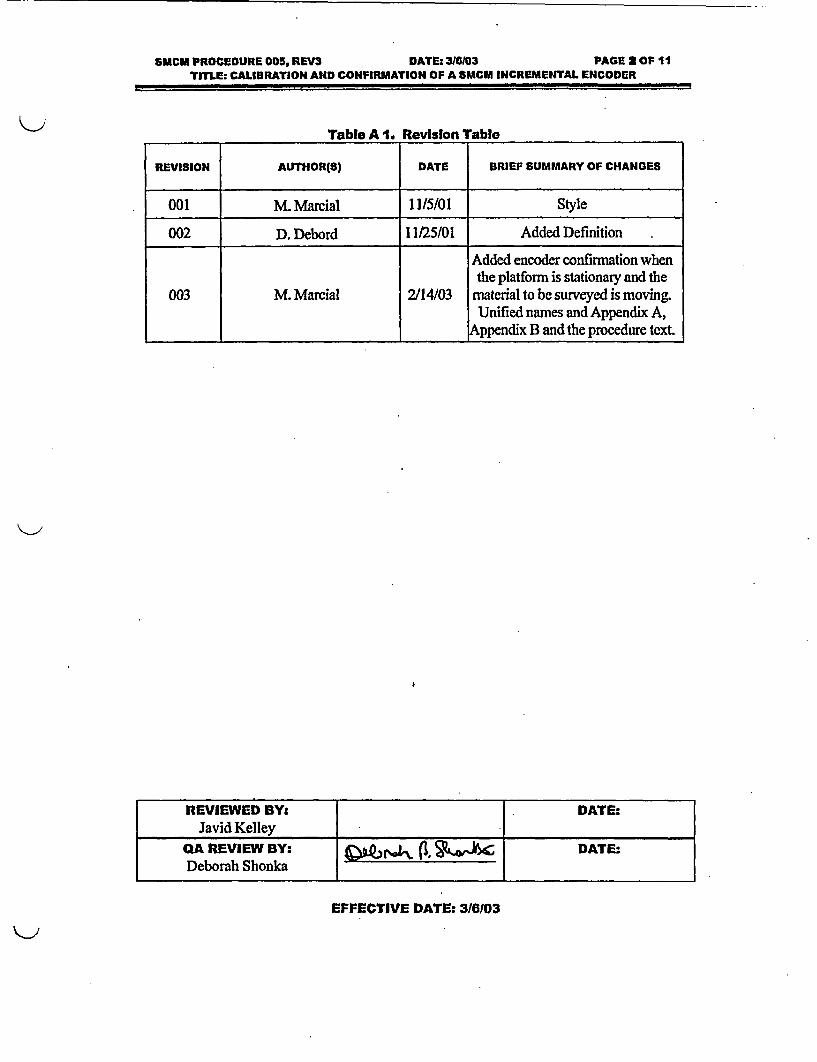
Table A 1. Revislon Table
REVISION AUTHOR(S) DATE BRIEF SUMMARY OF CHANGES
001 M. Marcial 11/5/01 Style
002 D. Debord 11/25/01 Added Definition
Added encoder confirmation whenthe platform is stationary and the
003 M. Marcial 2/14/03 material to be surveyed is movingUnified names and Appendix A,
Appendix B and the procedure text.
REVIEWED BY:. DATE:Javid Kelley - _
QA REVIEW BY: Q 1 (l CDATE:Deborah Shonka
EFFECTIVE DATE: 316/03

SMCM PROCEDURE 005, REV3 DATE: 3160X3 PAGE 2 OF 11TITLE: CALIBRATION AND CONFIRMATION OF A SMCM INCREMENTAL ENCODER
1. Purpose
The purpose of this procedure is to establish the methods for calibration and verificationof the incremental encoder included on the SMCM.
2. Scope and Limitations
Any SMCM used to conduct a rolling survey must have completed a valid encoderconfirmation. A new encoder confirmation must be performed IF any of the followingoccur.
I. Maintenance on the encoder.
2. Disassembly/re-assembly of the system or platform.
3. A new computer, software, or encoder is added to the cart.
4. 24 months since last confirmation.
5. Anomalies in the reported strip distance are noticed by the operator.
Calibration should be performed whenever the mean of an encoder confirmation exceeds1% error.
3. Definitions and Acronyms
ITEM
Table 1. Deilnltlons and Acronyms.DESCRIPTION
SMCM The Subsurface Multispectral Contamination Monitor is amobile platform containing detectors, support electronics,
and data logger used for conducting radiological landsurveys.
Incremental Encoder Electronic device used to measure distance via rotation.
Target Survey Speed Maximum survey speed determined to support requiredMDA.
MDA Minimum Detectable Activity.
TTL Transistor Transistor Logic
4A General Information
The incremental encoder provides a method of determining the distance traveled by theSMCM. As the encoder turns, TTL level pulses are generated at regular intervals. Acalibration factor in pulses per inch allows the SMCM to determine distance by numberof pulses. This calibration factor could be determined by dividing the pulses per rotation

SMCM PROCEDURE 005, REV3 DATE: 316103 PAGE 4 OF 11TILE. CALIBIRATION AND CONFIRMATION OF A SMCM INCREMENTAL ENCODER
by the circumference of the wheel. To reduce the impact of measurement error thisprocedure determines the calibration factor by rolling the cart a known distance anddividing by the pulses received by the counter card in the SMCM to get a pulse/in factor.The user must be cautious to operate the SMCM in straight lines. Failure to do so canresult in distance errors of more than 1%.
5. Materials, Equipment, and Supplies
Table 2. Materials, Equipment, and Supples.ITEM SPECIFICATION
SiMiCM Platform with installed'incremental encoder Any Model
SMCM Software Version 2.0 or later
Tape Measure or Laser Range 100 m or Suitable EquivalentFinder
Location marking Flags or Poles
Survey Documentation_ j Survey Logbook
6. Responsibilities6.1.Operator
6.1.1. Reads and becomes familiar with this procedure before performingcalibration.
6.1.2. Has successfully completed SMCM I training.
6.1.3. Ensures the measurements are performed according to thisprocedure.
7. Procedure7.1.Encoder Confrmatlon for Moving Plafforms
7.1.1. Mark a beginning position by placing a marker directly beneath thecenterline of the detector array.
7.1.2. Place a second marker at a distance of 30m for user-propelledsystems or lOOm for vehicular-propelled systems.
7.1.3. Initiate the measurement by pressing the "Record" button.
7.1.4. Begin moving the SMCM platform toward the second flag.
Note: The platform must be kept traveling In a straight line or the reported distance may bemisreported In relation to the actual distance.

651CM PROCEDURE 005, REV3 DATE: 316103 PACE I OF ItTITLE: CALIBRATION AND CONFIRMATION OF A SMCM INCREMENTAL ENCODER
7.1.5. Stop the platform when the centerline of the detector array lines upwith the second flag.
7.1.6. Complete the measurement by pressing the "Stop" key.
7.2.Encodor Confirmation for Stationary Platforms
7.2.1. If a conveyor is used to transport material by the stationary SMCMthen follow this section.
7.2.2. Measure the distance of the conveyor belt that the wheel encoderwill ride on.
7.2.3. Mark the belt. This mark will be used to start and end the recordingof a strip.
7.2.4. Initiate the measurement by pressing the "Record" button when themark passes by a reference point.
7.2.5. Record a strip that is at least 75 meters. The belt may need to makemore than I revolution.
7.2.6. Stop the measurement by pressing the "Stop" button when the markpasses by the starting reference point.
*7.2.7. Calculate the actual distance the mark traveled.
7.3.Encoder Confirmation Evaluation
7.3.1. Record the reported and actual distances (in meters) in Appendix A"Incremental Encoder Calibration Verification Data Sheet."
7.3.2. Repeat steps 7.1 or 7.2 two additional times for a total of threemeasurements.
7.3.3. Calculate the mean and the percent deviation from the mean for eachof the three measurements using Equation 1. Record the mean andpercent deviation from the mean for each measurement in AppendixA "Incremental Encoder Calibration Verification Data Sheet!'
Equation IDMean - Measurement
Deviation% = Mean *100
7.3.4. If the mean of the three measurements differs from the actualdistance by more than 1%, proceed to 7.4 and perform an encodercalibration.

SMCM PROCEDURE 005, REV3 DATE: 316103 PAGE S OF IITITLE: CALIBRATION AND CONFIRMATION OF A SMCM INCREMENTAL ENCODER
7.3.5. Calculate the percent deviation of the mean from the actual distanceusing Equation 2. Record the value in Appendix A "IncrementalEncoder Calibration Verification Data Sheet."
Equation 2Deviation% = IMean - ActualLength * 100
Mean7.3.6. If the deviation from the mean is larger than 3% for any
measurement, repeat the confirmation test or troubleshoot encoder.
7.A.Encoder Calibration
7.4.1. Perform confinuation measurements outlined in 7.1 or 7.2.
7A.2. Record the mean of the three confirmation measurements in thelogbook.
7.4.3. Calculate a new encoder calibration constant based on theconfirmation measurements average. Record the following on theAppendix B "Encoder Calibration Data Sheet":
* Enter the old encoder calibration constant in Constantold
* For conveyor systems, enter the actual distance the mark traveledin ActualDistance.
* For user-propelled systems, enter the 30 in ActualDistance.
* For vehicular-propelled systems, enter 100 in ActualDistance.
* Enter the value shown on the SMCM Process software screenlabeled "Distance Traveled [in]" in REportedDistance.
7.4.4. Set software to new encoder calibration constant.
7.4.5. Perform encoder confirmation in Section 7.1 to verify new encodercalibration constant.
8. Acceptance CntenaCompletion of a successful encoder confirmation routine.
All encoder confirmation and/or calibration information has been recorded in thesurvey logbook.

SMCM PROCEDURE 005, REVS3 DATEt 316103 PAGE T OF 11TITLE: CALIBRATION AND CONFIRMATION OF A SMCM INCREMENTAL ENCODER
9. References9.1.SMCM Procedure 005, uRoquIrements for Completion of a Survey Using the
SMCM."
10. RQuired Records10.1. Survey Logbook
11. Appendices11.1. Appendix A: Incremental Encoder Calibration Verification Data Sheet
11.2. Appendix B: Encoder Calibration Data Sheet

SMCM PROCEDURE 005, REV3 DATE: 316103 PAGE 0 OF 11TITLE: CALIBRATION AND CONFIRMATION OF A SMCM INCREMENTAL ENCODER
Appendix A
Znenl Encde Cabrafon VeuifiaHon Data Sheet

SMCM PROCEDURE 005, REV3 DATE: 316/03 PACE D OF 11TITLE: CALIBRATION AND CONFIRMATION OF A SMCM INCREMENTAL ENCODER
Em
Appendix A
Incremental Encoder Calibration Verification Data Sheet
Date: SMCM S/N:
SMCM Speed:
Note: The test should be performed at the Intended survey speed.
Table 1: Strip Distances
Measurement DIstance (Moters) Dev. From Mean (%) Dev. From Mean UmitMl)
1 3
2 3
33
Mean N/A N/A
Actual Distance* N/A N/a
*Distance between flags for moving platforms or marks on a conveyor for stationary platforms.
Mean deviation from actual distance: %
Mean Deviation from Actual Distance less than 1%
Deviation from Mean for each Measurement within 3% of the Actual Distance
Lmit
Init
Performed By:
Reviewed By:
Date:
Date:
Time:_
Time:

SUCH PROCEDURE 005, REV3 DATE: 316103 PAGE 1 OF 11TITI.ES CALIBRATION AND CONFIRMATION OF A SUCM INCREMENTAL ENCODER
Appendix B
EncodrCudon D[M SheA

8MCM PROCEDURE 005, REV3 DATE: 318103 PAGE 11 OF 11TITLE: CALIBRATION AND CONFIRMATION OF A 551CM INCREMENTAL ENCODER
Appendix B
Encoder Calibration Data Sheet
Date: SMCM SIN:
SMCM Speed:
Note: The test should be performed at the intended survey speed
ReportedDistance (this is the value shown on theSMCM Process software screen labeled "DistanceTraveled [m]") Enter the mean of 3 distance Inmeasurements.
Constantowi
ActualDISTANCE (Distance between flags formoving platforms or marks on a conveyor forstationary platforms.)
pulse/m
m
ConstantNw = Constantold *ActualDISTANCEREporledDistance
ConstantN,, : pulse/m
Init SMCM Process software updated with ConstantN,,
Init Perform encoder confirmation.
Performed By: Date: Time:
Reviewed By: Date: Time:

PROCEDURE: SMCM 006
Requirements for Completion of a Survey Usingthe SMCM
Thorium Remediation ProjectTulsa, Oklahoma
REVISION: 03
EFFECTIVE DATE: APRIL 2004
A.f 1'-' ';'
J.W. (Bill) Vinzant / Kaiser Aluminum & Chemical Corporation Date Approved:

PROCEDURE: SMCM 006
Requirements for Completion of a Survey Using- the SMCM
Thorium Remediation ProjectI . Tulsa, Oklahoma
REVISION: 03
EFFECTIVE DATE: APRIL 2004
L'2,l~2,,LReviewed by: .Date: Quality Control Manager. -Date:

Control Copy #__
Shonka Research Associates, Inc.4939 Lower Roswell Road, Suite 106Marietta GA 30068770-509-7606
Subsurface Mul-specral ContaminationMonitor
SM.M Procedum 006, Rev 3
F-%IN~sp**rConieon ofa Sureyr UsbVte SMCM

SMCM PROCEDURE 006, REV3 DATE: 411104 PAGE 2 OF 8TITLE: REQUIREMENTS FOR COMPLETION OF A SURVEY USING THE SMCM
Table A 1. Revision Table
REVISION AUTHOR(S) DATE BRIEF SUMMARY OF CHANGES
000 _M. Marcial 11/12/01 Major Revision to 001
001 D. Debord 11/25/01 Stop Work Conditions
. Added section when SMCM
002 M. Maxial 2114/03 platform is used in stationary modeand a conveyor tanwsports material._ _ by the system.
003 K Murray 4/1/04 Added assessment of Stop Work____ ___ ____ ___ ____ ___ _ __ __ I C onditions.
REVIEWED BY: DATE:Michael MarcialQA REVIEW BY: (I . DATE:Deborah Shonka
.I
EFFECTIVE DATE: 411104

SMCTA PROCEDURE 00% REV3 DATE. 411104 PAGE 3 OF 8TME: REQUIREMENTS FOR COMPLETION OF A SURVEY USING THE SMCM
1. Purpose
The purpose of this procedure is to detail the requirements for completion of a survey using theSMCM.
2. Scope and limtftions
This procedure applies to version 1.0 or later of the process software.
3. Definitions and Acronyms
Table 1. De finitons and Acronyms.
ITEM T DESCRIPTION
SMCM The Subsurface Multispectral Contamination Monitor is amobile platform containing detectors, support electronics, anddata logger used for conducting radiological surveys.
SIMS Survey Information Management System - SIMS is flexibleand comprehensive interfacing software for the SRA SMCM.SIMS processes the SMCM instrument data with asophisticated data parser, integrated spreadsheet, and powerfulspecial functions such as spatial data filters. SIMS provides themost flexible reporting system available for printing surveyrecords or complete stand-alone survey reports. SIMS containsall the tools needed to meaningfully communicate between theSMCM and the data analysis team.
Nal M-Style detector with the photo multiplier tube opticallycoupled to a NaI crystal. A mu-metal magnetic/light shield overthe PMT completes the detector. A low energy X-ray leadumbrella shield covers the detector and PMT. The detector isattached to a preamplifier and encased in a thermally insulatedelectrically shielded container.
SRC Source Response Check-Determines if the detector is_operating the same from day-to-day.
PBC Performance Based Check - Provides measurement of thesystem_'s performance in field conditions.
ROI Region of Interest - Channels assigned to a particular isotope.
MCA Multi-Channel Analyzer-Equipment used to view spectral data.

SMCT. PROCEDURE 006, REV3 DATE: 41104 PAGE 4 OF 8TITLE: REQUIREMENTS FOR COMPLETION OF A SURVEY USING THE SMCM
4. General Irbrmation4.1. Scanning Mode
Upon arrival on site, the encoder will be checked per SMCM Procedure 005 and the NaIs will besource checked per SMCM Procedure 004 and calibrated per SMCM Procedure 007.
The array mounted Nal detectors can be used for both scanning and in situ. Survey speed willbe established by the Project Manager based on the isotopes of concern and sensitivity to beattained.
For Moving Plasfonns: A survey is conducted in a series of strips, which can be reassembled inSIMS to provide complete documentation of a survey without requiring any manual transfer ofdata. To accomplish a survey an operator first makes a crude sketch of the area and indicates thedirection and start point of each strip. The file name of the survey should be recorded on thesketch and a reference coordinate for the South West comer of the survey area should be noted.The survey is divided into strips by placing large markers and flags on opposing edges of thesurvey area. The operator starts the SMCM software if it is not already active and enters thesurvey parameters: Survey Name (File Name), and Operator ID. The SMCM platform scansstrait strips of the survey area. Once the entire accessible survey area has been covered by theSMCM, the survey is complete. In situ measurements may be incorporated into the survey inareas that are not accessible to the SMCM.
For Stationary Platf orms: A survey is conducted in a series of strips, which can be reassembledin SIMS to provide complete documentation of a survey without requiring any manual transferof data. To accomplish a survey an operator decides what a collection of strips will represent,i.e., a 250-ton pile of material, a B-25 container, etc. The filename of the survey should berecorded in the logbook. The operator starts the SMCM software if it is not already active andenters the survey parameters: Survey Name (File Name), and Operator ID. The SMCM platformscans strips of the survey material. This procedure will reference the movement of the materialpast the SMCM platform as a conveyor. Other conveying mechanisms may be used besides atypical conveyor with belt. Once the entire collection of strips area has been covered by theSMCM, the survey is complete.
4.2. Xbof& mode
In situ surveys using the SMCM platform should be performed per SMCM Procedure 002.

3M1CU PROCEDURE 006, REV3 DATE. 41/04 PAGE 5 OF 8TITLE: REQUIREMENTS FOR COMPLETION OF A SURVEY USING THE SMCCM
5. Mateials, Equipment, and Supplies
Table 2. Materials, Equipment, and Supplies.ITEM SPECIFICATION
SMCM platform Any platform with detector heights and spacing asi determined by survey team leader.
Soft1w- -____ _ _ __ __ _
Software I SMCMProcess
Field Notes Logbook
Reference markers Existing landmarks or identified known GPS locations
Strip markers Flags or Equivalent
Differential GPS (if available) Any device capable of outputting NEMA strings that theSMCM Prcess software can interpret I
6. Responsibilities
6.1. Operator
6.1.1. Reads and becomes familiar with this procedure before performingcalibration.
6.1.2. Ensures all surveys are performed according to this procedure.
6.1.3. Operates the SMCM during the survey.
6.1.4. Guides and Monitors the SMCM's speed throughout the surveys.
6.1.5. Has successfully completed SMCM I training.
6.2. Project Manager
6.2.1. Reads and becomes familiar with this procedure.
62.2. Confirms the quality of SMCM operations.
6.2.3. Periodically confirms quality of collected SMCM data.
62.4. Has successfully completed SMCM II Training.
6.2.5. Establish SMCM survey speed and NaI temperatures.
7. Procedure
7.1. Initial SMCM Preparation
7.1.1. Confirm the survey platform is in good worldng condition and is setupappropriately for the survey area environment.

SMCM PROCEDURE 006, REV3 DATE: 411/04 PAGE 6 OF 8TITLE REQUIREMENTS FOR COMPLETION OF A SURVEY USING THE SMCM
7.1.2. ForMovingPlaforms: Establish a reference heading e.g. Magnetic, True,or Map North, or a direction based on permanent site landmarks. All datastrips will be taken parallel or perpendicular to the reference heading.
7.1.3. Turn detector heaters on and set thermostat to temperature determined byProject Manager.
WARNGThe temperature of theNaldetedors should not exceed 100 F.
7.1.4. For Moving Ptaforms: When available, turn differential GPS on.
7.1.5. Calibrate SMCM encoder per SMCM Procedure 005.
7.1.6. If not already done, calibrate NaI detectors per SMCM Procedure 007.
7.2. Survey Setup
7.2.1. If using a gas generator, ensure there is enough gas in the generator toIcomplete the survey area:
7.2.2. If using the radon detector, start the pump 20 minutes before data collection.
7.2.3. If using the detector thermal stabilizers, start the electronics 20 minutesbefore data collection.
7.2.4. Start the SMCM software if it was not already running.
7.2.5. Align detectors using the SMCM Process software alignment feature.
7.2.6. If this is the beginning of a shift, perform daily Source Response Check andPerformance Based Check per SMCM Procedure 004.
7.2.7. For Moving Pla forms: Establish a survey grid. The edges of the surveygrid must be parallel or perpendicular to the established reference heading.Square or rectangular (with the longer edge being the primary direction oftravel) survey grids are generally more efficient. The time of the surveygenerally increases with the number of strips required to cover the grid.
7.2.8. For Moving Pla oorms: Make a crude sketch of the survey area includingdistances.
7.2.9. For Moving PlaoJorms: Identify SW comer on drawing and provide areference coordinate, if available.
7.2.10. For Moving Plaforms: When available, take a differential GPS reading inthe South West comer of the survey grid.
7.2.11. Record the date, time, location, and detector temperatures in the logbook.
7.2.12. For Moving Plabforms: Indicate strip locations and directions on sketch witharrows.
7.2.13. For Moving Plabforms: Identify and mark the first survey lane using a tapemeasure and stake or other markings. Center a stake at the end of the firststrip.

SMCM PROCEDURE 006, REV3 DATE: 411104 PAGE 7 OF 8TITLE: REQUIREMENTS FOR COMPLETION OF A SUMVEY USING THE SMCM
7.3. Scanning Survey Operations
7.3.1. When prompted by the SMCM softvare, enter a survey name and record thename on the sketch of the survey. For stationary platforms, there is nosketch of the area.
7.3.2. For Moving Platforms: When possible, move the SMCM platform to theSouth West comer of the survey grid. Else, move to the most easilyaccessible corner, and align the detector array even with the edge of thesurvey grid, pointed in the direction of travel.
7.3.3. Start recording the strip by hitting the <Start> button in the SMCMsoftware. For Stationary Platforms, assure the conveyor is clear of material.After pressing the start button, the SMCM process software will indicate itis ready for material after its internal filters are conditioned. The initialconditioning of the filters happens only when the software is first started orthe operator performs a filter reset.
7.3.4. For Moving Platforms: Using a marker at the other side of the survey gridas a target, drive the array across the survey area at the speed determined bythe Project Manager.
7.3.5. For Moving Platforms: If obstacles prevent completing the strip, stop thestrip by hitting the <Stop> button in the SMCM software, note on surveysketch, start a second strip on the other side of the obstacle, or turn theplatform around and repeat steps 7.3.3 through 7.3.5.
7.3.6. For Stationary Platforms: After a pre-determined time or if the conveyor isout of material, stop the strip by pressing the <Stop> button. The ProjectManager determines the predetermined time of a typical strip. The SMCMsoftware may stay in record mode when no material is present. However, itis not recommended to un-necessarily record background data.
7.3.7. For Stationary Patforms: If the SMCM Process software indicates analarm, then wait for the conveyor to stop, and then stop the strip by pressingthe <Stop> button. Use the SMCM Process software post-visualizationfeature to identify the type of alarm and its location along the conveyor.
7.3.8. For Moving Platforms: Once the array is over the marker at the oppositeedge of the survey grid, hit the <Stop> button to complete the survey strip.
7.3.9. For Moving Plaform=s: Turn the array around and align it next to theprevious one.
7.3.10. Monitor the SMCM Process software alignment peak window after everystrip, every 30-minutes or whenever it is suspected that the system isbecoming misaligned. Mis-alignment is typically seen when the ambienttemperature is changing.
7.3.11. Repeat 7.3.3 through 7.3.7 until all accessible areas of the survey grid havebeen surveyed.
7.3.12. Record the stop time in the logbook.

SMCM PROCEDURE 006, REV3 DATE:Y 411104 PAGE S OF 8TITLE: REQUIREMENTS FOR COMPLETION OF A SURVEY USING THE SMCM
7.3.13. Perform Performance Based Checks in accordance with SMCM Procedure004
7A. Stop work conditions
Note: Under the following conditions, an assessment shall he made that evaluates if theseconditions impact survey data.
7A.1. Onset of moderate rain or snowfall that removes radon daughters from airand their impact on product measurement.
74.2. Standing water in excess of .5 inches deep or snow in excess of 6 inchesdeep over areas larger than 1O rn2 , unless specifically approved by theProject Manager.
7.4.3. Movement of sources greater than 50 nCi at a distance of 1 meter from adetector. The activity shall be adjusted for inverse square relation.
7.4.4. Rapid change in ground level radon daughter product concentration due toinversion.
7.4.5. Large temperature changes.
8. Acceptance Criteia
None, outside ofthe reference procedures.
9. Refrnces9.1. SMCM Procedure 005 "Callbration and Confirmation of Incremental Encoder"
92. SMCM Procedure 004 "Source Response Checks and Performance Based Checks ofany Mal Detector Configuration Installed on the WMCM"
9.3 SMCM Procedure 007 "Callbration of Hal detector"
10. Required Records
N/A
11. Appendices
NIA

PROCEDURE: SMCM 007
Calibration of Nal DetectorThorium Remediation Project
Tulsa, Oklahoma
REVISION: 02
EFFECTIVE DATE: APRIL 2004I,
,/ 1-=, - o
J.W. (Bill) Vinzant I Kaiser Aluminum & Chemical Coporation Date Approved,

PROCEDURE: SMCM 007
Calibration of Nal DetectorThorium Remediation Project
Tulsa, Oklahoma
REVISION: 02
EFFECTIVE DATE: APRIL 2004
Reviewed by: Date: Quality Control Manager:-Dte Date:

Control Copy #_ _
Shonka Research Associates, Inc.4939 Lower Roswell Road, Suite 106Marietta GA 30068770-509-7606
Subsurface Multi-spectral ContaminationMonitor
SM=M PWCedM W07, fV2
Caton af NWDetecDow

SMCM PROCEDURE 007, REV2TmTLE., CALIBRATION OF NMA DETECTOR
DATE: 3J6/03 PAGE 2OF 6
Table A 1. Revislon Table
REVISION AUTHOR(S) DATE BRIEF SUMMARY OF CHANGES
000 M. Marcial 11/5/01 Major Revision to 003
001 D. Debord 11/25/01 Added Calibration Stickers
Added Project Manager002 M. Marcial 2/14/03 responsibilities. Added required
records.
REVIEWED BY: DATE:Javid Kelley
QA REVIEW BY: QLZ P|L%, DAATE:Deborah Shonka A
EFFECTIVE DATE: 3/6103

SMCM PROCEDURE,007, REV2 .TITLE: CALIBRATION OF NAI DETECTOR
DATE. 3t6103 PACE 3 OF 6
- DATE.� 3I6� PAGE 3 OF 6
1. Purpose
The purpose of this procedure is to define the operational methods and requirements forperforming a detector/source calibration with any MMdil.
2. Scope and Umitations
N/A
3. Defintions and Acronyms
Table 1. Definitions and Acronyms.ITEM DESCRIPTION
| The Subsurface Multispectral Contamination Monitor is a
SMCM ! mobile platform containing detectors, support electronics, anddata logger used for conducting radiological surveys.
Survey Information Management System - SIMS is flexibleand comprehensive interfacing software for the SRA SMCM.
SIMS processes the SMCM instrument data with asophisticated data parser, integrated spreadsheet, and powerful
SIMS pecial functions such as spatial data filters. SIMS provides themost flexible reporting system available for printing survey
records orcomplete stand-alone survey reports. SIMS containsall the tools needed to meaningfully communicate between the
SMCM and the data analysis team.
M-Style detector with the photo multiplier tube opticallycoupled to aNa crystal. A mu-metal magnetic/light shield over
Nal the PMT completes the detector. A low energy X-ray leadumbrella shield covers the detector and PMT. The detector isattached to a preamplifier and encased in a thermally insulated
i_ electrically shielded container.
a SRC Source Response Check - Determines if the detector islR _ operating the same from day-to-day.
PBC Performance Based Check - Provides measurement oftheIB system's performance in field conditions.
ROI I Region of Interest-Channels assigned to a particular isotope.

SMCM PROCEDURE 007, REV2TfTLE: CALIBRATION OF NAI DETECTOR
DATE: 3/6103 PACE 4 OF e
DATE: 3/6103 PAGE4OF 6
4. General Information
Before any gamma spectroscopy in support of land surveys are performed with Na!detectors, all detectors must be calibrated. The data collected from the calibration will beused to calculate calibration factors for the duration of the survey. The calibration factorwill convert count rate into planar or deposited concentrations.
5. Material Equipment and Supplies
Table 2. Materials, Equipment, and Supplies.ITEM I SPECIFICATION
Detector Any size NaI or equivalent gamma detector.
Software I MCB software
NIST traceable Check 60 Co 137CS & other if Scope requires.Sources _ _Co,_ _ _ _ _ _ _ _ _ _ _ _ _ _ _ _ _
Hardware I prAce or ulNomad MCA
Computer Desktop PC orPocketPC
Field Notes Log Book
6. Pesponsibilities
6.1. Technician
6.1.1. Reads and becomes familiar with this procedure.
6.1.2. Ensures that all measurements are made in accordance with thisprocedure.
62. Project Manager
62.1. Determines the calibration source and count times to use.
6.22. Ensures that all measurements are made in accordance with thisprocedure.

SMCM PROCEDURE 007, REV2 DATE: 31803 PAGE 5 OF 6TITLE: CALIBRATION OF NAI DETECTOR
7. Procedure
7.1. Alignment of Nal Spectrum
7.1.1. Prior to performing the calibration, alignment of the spectrum channelsshall be performed.
7.1.2. Alignment shall occur for each detector in use.
7.1.3. The alignment is typically performed using the 40K background peak.
7.1.4. The alignment is performed by adjusting the gain in the SMCM orMCA software to shift the 40K peak until the center of the 1461 keVpeak is centered in channel 250, when the multi-channel analyzer is setto a conversion gain of 512 channels.
7.2. Calibration of Hal Detectors
7.2.1. Prior to field use, each Nal detector will be calibrated to NISTtraceable sources. Calibrations will include 640Co and 137CS sealedsources, or other isotopes approved by the Project Manager based onthe specific survey requirements.
7.2.2. Calibration of the Nal detector will be performed by taking a 10-minute background using the NaI detectorfMCA system.
7.2.3. Then take a 10-minute count with the source exactly 1 meter below thebottom face of the crystal. The count time may be varied based uponthe source strength. (determined by the Project Manager).
7.2.4. Visually inspect the recorded peak and record the net counts, centerchannel and FWHM in the logbook.
7.2.5. Record the background and source spectra in the computer as a *.CHNfile.
7.2.6. Perform Source Response Check and Performance Based Check inaccordance with SMCM Procedure 004 to establish traceability to thecalibration measurement.
7.2.7. Affix a calibration sticker to the detector. The due date shall notexceed 6 months from the current date.
72.8. Repeat steps 7.2.2 to 7.2.7 for each detector to be used.

SMCM PROCEDURE 007, REV2 DATE: 36103 PAGE 6 OF 6TITLE. CAUBRATION OF NHU DETECTOR
8. Acceptance crfterja
8.1. Reported source to Nal crystal distance i3 within t5mm.
9. References
N/A
10. Required Records
10.1. Background and Source *.CHN flies.
11. Appendices
N/A

PROCEDURE: Mark III Contamination Monitor 001
Calibration of Mark mI Contamination MonitorNal Detector
Thorium. Remediation ProjectTulsa, Oklahoma
REVISION: 00
EFFECTIVE DATE: APRIL 2004
*Xov 4- e2 ~
1.W. (Bill) Vinzant / Kaiser Aluminum & Chemical Corporation Date Approved:

K- I
PROCEDURE: Mark III Contamination Monitor 001
Calibration of Mark III Contamination MonitorNal Detector
Thorium Remediation ProjectTulsa, Oklahoma
REVISION: 00
EFFECTIVE DATE: APRIL 2004
±~-o~ AUoyReviewed by: -Date: e Quality Control Manager: Date:

Control Copy #__
Shonka Research Associates, Inc.4939 Lower Roswell Road, Suite 106Marietta GA 30068770-509-7606
MkdDI Contamination Monitor
uamM Pcec001, R0
Callbtion of MNdIICM NaM Detetor

&MKIIICM PROCEDURE 001, REVOTITLE: CAUBRATION OF MKIIECM NAI DETECTOR
DATE: 411104 PAGE 2OF 5
Table A 1. Revision Table
REVISION AUTHOR(S) DATE BRIEF SUMMARY OF CHANGES
REVIEWED BY: DATE:
QA REVIEW BY: DATE:
EFFECTIVE DATE: 411/04
MKIIICU PROCEDURE 001, REVOTITLE: CAUBRATION OF MKIIICM NA_ DETECTOR
DATE: 4M104 PAGE 30 F5
DATE: 411104 PAGE 3 OF 5
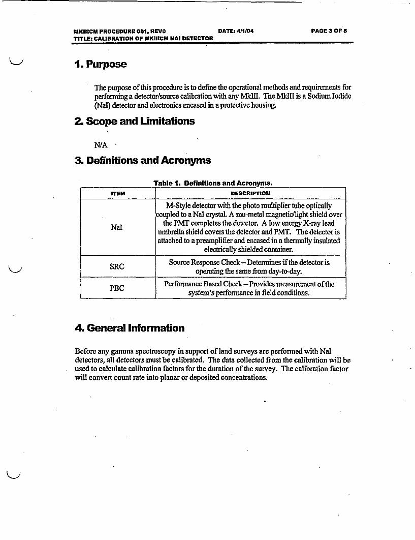
1. Purpose
The purpose ofthis procedure is to define the operational methods and requirements forperforming a detector/source calibration with any MMIll. The MkIIl is a Sodium Iodide(Nal) detector and electronics encased in a protective housing.
2. Scope and Urmitations
N/A
3. Definitions and Acronyms
Table 1. DefinItlons and Acronyms.
ITEM DESCRIPTION
M-Style detector with the photo multiplier tube opticallycoupled to a NaI crystal. A mu-metal magnetic/light shield over
Nal the PMT completes the detector. A low energy X-ray leadNa umbrella shield covers the detector and PMT. The detector is
attached to a preamplifier and encased in a thermally insulatedelectrically shielded container.
SRC Source Response Check - Determines if the detector is__ operating the same from day-to-day.
PBC Performance Based Check -Provides measurement of thesystem's performance in field conditions.
4. General Information
Before any gamma spectroscopy in support of land surveys are performed with NaIdetectors, all detectors must be calibrated. The data collected from the calibration will beused to calculate calibration factors for the duration of the survey. The calibration factorwill convert count rate into planar or deposited concentrations.

MKIIICM PROCEDURE 001, REVOTITLEs CALIBRATION OF MKIIICM NAI DETECTOR
DATEs 411104 APAGE 4 OF 5
5. Material Equipment and Supplies
Table 2. Materials, Equipment, and Supplies.,
: _
ITEM SPECIFICATION
Detector Any size NaI or equivalent gamma detector.
NIST traceable Check 60Co, '"Cs & other if Scope requires.Sources
Computer PocketPC
Field Notes Log Book
6. Responsibilities
6.1. Technician
6.1.1. Reads and becomes familiar with this procedure.
6.1.2. Ensures that all measurements are made in accordance with thisprocedure.
6.2. Project Manager
6.2.1. Determines the calibration source and count times to use.
6.2.2. Ensures that all measurements are made in accordance with thisprocedure.
7. Procedure
7.1. Calibration of MkIlICM Mal Detectors
7.1.1. Prior to field use, each Nal detector will be calibrated to NISTtraceable sources. Calibrations may include 6"Co and '7Cs sealedsources, or other isotopes approved by the Project Manager based onthe specific survey requirements.
7.1.2. Perform a 10-minute background of the NaI detector.

MK111CM PROCEDURE 001, REVOTITLE: CAUBRATION OF MKIIICU NAI DETECTOR
DATE. 4/1104 PAGE 6 OF 5
- DATE: 411104 PAGE 5 OF 5
7.1.3. Perform a 10-minute count with the source placed one meter from thecenter of the detector. The count time may be varied based upon thesource strength. (Determined by the Project Manager).
7.1.4. Review the data collected.
7.1.5. Perform Source Response Check and Performance Based Check (ifapplicable) in accordance with MkIIICM Procedure 005 to establishtraceability to the calibration measurement.
7.1.6. Affix a calibration sticker to the detector. The due date shall notexceed 6 months from the current date.
7.1.7. Repeat steps 7.1.2 to 7.1.6 for each detector to be used.
8. Acceptance criteria
8.1. Reported source to Nal crystal distance Is within 15mm.
9. References
N/A
10. Required Records
10.1. CalIbratlon data shoots
11. Appendices
N/A

PROCEDURE: Mark III Contamination Monitor 002
Requirements for Completion of a Survey Usingthe In Situ Contamination Bucket Monitor
Thorium Remediation ProjectTulsa, Oklahoma
REVISION: 00
EFFECTIVE DATE: April 2004
./'X.I- ep '.5.,
J.W. (Bill) Vinzant / Kaiser Aluminum & Chemical Corporation Date Approved:

PROCEDURE: Mark III Contamination Monitor 002
Requirements for Completion of a Survey Usingthe In Situ Contamination Bucket Monitor
Thorium Remediation ProjectTulsa, Oklahoma
REVISION: 00
EFFECTIVE DATE: April 2004
(7,- IV �,� ,Reviewed by: Date:.
QQuality Control Manager Date:

Control Copy #_ _
Shonka Research Associates, Inc.4939 Lower Roswell Road, Suite 106Marietta GA 30068770-509-7606
MklIl Contamination Monitor
kSdIICM Pmceda n W2, ReO
Reqi"mens for Compbeion of a SWBy Ushm tH ICBM

MKIIICM PROCEDURE 002 REVO DATE: 4M104TITLE: REQUIREMENTS FOR COMPLETION OF A SURVEY USING THE ICBM
PAGE 2 OF 5
REVIEWED BY:. DATE:
QA REVIEW.BY: DATE:
. 5
EFFECTIVE DATE: 4/1104

1KIIICM PROCEDURE 002 REVO DATE: 411104TITLE: REQUIREMENTS FOR COMPLETION OF A SURVEY USING THE ICBM
PAGE 3 OF 5
1. Purpose
The purpose of this procedure is to define the operational methods and requirements for usinga MkIIl as a sub-system in a In Situ Contamination Bucket Monitor (ICMB). The MkIil is aSodium Iodide (Na!) detector and electronics encased in a protective housing.
2. Scope and Umitations
N/A
3. Definitions and Acronyms
Table 1. Deffnitlions and Acronyms.ITEM DESCRIPTION
ICBM The In Situ Contamination Bucket Monitor containinga Nal detector encased in a protective housing used forestimating activity of the soil excavated or loaded.
Nal M-Style detector with the photo multiplier tubeoptically coupled to a NaI crystal. A mu-metalmagnetic/light shield over the PMT completes the
L detector. A low energy X-ray lead umbrella shieldcovers the detector and PMT. The detector is attachedto a preamplifier and encased in a thermally insulatedelectrically shielded container.
SRC Source Response Check - Determines if the detector isoperating the same from day-to-day.
L _ _ _ _ _ _ _ _ _ _ _ _ _ _ _ _ _ _ _ _ _ _ _ _ _
4. General Information
The In Situ Contamination Bucket Monitor optimizes where to stop digging,identification of unknown material, and estimating activity of raw material placed into adump truck.

UKIIICM PROCEDURE 002 REVO DATE: 411104 PAGE 4 OF 5TITLE: REQUIREMENTS FOR COMPLETION OF A SURVEY USING THE ICBM
5. Material Equipment and Supplies
Table 2 . Materials, Equipment, and Supplies.ITEM I SPECIFICATION
Nal detector i Model 3
QC Check Source Typically a Cs-137 source
Field Records i Log book
6. Responsibilities
6.1. Technician
6.1.1. Reads and becomes familiar with this procedure.
6.1.2. Ensures that all measurements are made in accordance with thisprocedure.
6.2. Project Manager
6.2.1. Ensures proper placement of ICBM on excavator or equivalent.
6.2.2. Reviews the survey information.
7. Procedure
7.1. Calibration of MkIIICM Nal Detectors
7.1.1. Calibration shall be performed per MkIIICM Procedure 001.
7.2. Source Response and Performance Based Check of Hal detectors
7.2.1. The Source Response and Performance Based Checks for the Nal aredescribed in MkJI1CM Procedure 005.

MKIIICM PROCEDURE 002 REVO DATE: 411104 PAGE 5 OF 5TITLE: REQUIREMENTS FOR COMPLETION OF A SURVEY USING THE ICBM
7.3. Operation of the ICBM
7.3.1, Turn on Pocket PC to activate the ICBM. This can be done eitherfrom the cab of the equipment or from the ground.
7.3.2. Ensure the total is reset for counting bucket loads, for each truck thatis.
7.3.3. Start logging data from the ICBM prior to excavating or loading.
7.3.4. Upon completion of excavating or loading stop data logging on thePocket PC.
7.3.5. Return the Pocket PC to technician if applicable for review of datacollected.
8. Acceptance criteria
Surveys performed in accordance with this procedure are designed to identify different levelsof radioactivity for possible segregation of soil.
Response check data shall be evaluated for the survey. Control chart data should indicatespecific acceptance criteria for the survey being performed. Response check values outside theprescribed acceptance band shall be evaluated for their impact on the survey and dispositionedor those areas impacted re-surveyed.
9. References
9.1. MkIIICM Procedure 0019 "Calibration of MkIIlCM Nal Detector"
9.2. MkIIICM Procedure 005, SSourco Response Checks and Performance BasedChecks of any MkIIICM Nal Detector"
10. Required Records
N/A
11. Appendices
N/A

PROCEDURE: Mark III Contamination Monitor 003
Requirements for Completion of a Survey Usingthe Walk over Activity Monitor
Thorium Remediation ProjectTulsa, Oklahoma
REVISION: 00
EFFECTIVE.DATE: April 2004
J.W. (Bill) Vinzant /Kaiser Aluminum & Chemical Cor
- e:� ��
Date Approved:

PROCEDURE: Mark III Contamination Monitor 003
Requirements for Completion of a Survey Usingthe Walk over Activity Monitor
Thorium Remediation ProjectTulsa, Oklahoma
REVISION: 00
EFFECTIVE DATE: April 2004
- (0-1 d L24 -Reviewed by:
ID QDate: Quality Control Manager: Date:

I Rnlqnd Wood - MkIWHCM Procedure 003 RevO.Ddf Page 1 !Ir, 7 7--- 7-: , - ------
( ? Control Copy#___
Shonka Research Associates, Inc.4939 Lower Roswell Road, Suite 106Marietta GA 30068770-509-7606
Mkill Contamination Monitor
MkIllCM Procedure 003, Rv0
Requirements for Completion of a Survey Using the ROAM

- i
I Roland Wood - MkIWHCM Procedure 003 RevO.pdf Page 2 ;
MKIIICM PROCEDURE 003 REVO DATE: 411104TITLE: REQUIREMENTS FOR COMPLETION OF A SURVEY USING THE ROAM
PAGE 2 OF 6
Table A 1. Revislon Table
IREVISION I AUTHORES) I DATE I BRIEF SUMMARY OF CHANGES
EFFECTIVE DATE: 411104

I Ro'land Wood - MkI11CM Procedure 003 RevO.Ddf Page 3RolandI: Wod-MII rcdr 00 RevOodfPag 3
MKIIICM PROCEDURE 003 REVO DATE: 411104 PAGE 3 OF 3
TITLE: REQUIREMENTS FOR COMPLETION OF A SURVEY USING THE ROAM
1. PurposeThe purpose of this procedure is to define the operational methods and requirement forperforming Roll Over Activity Monitor (ROAM) gamma surveys usirg a Sodium Iodide(Nal) detector.
2. Scope and Limitations
N/A
3. Definitions and Acronyms
Table 1. Definitions and Acronyms.
ITEM DESCRIPTION
ROAM The Roll Over Activity Monitor is a mobile platformcontaining Nal detectors and data logger used forconducting radiological surveys.
Nal M-Styledetector with the photo multiplier tubeoptically coupled to a Nal crystal. A mu-metalmagnetic/light shield over the PM T completes thedetector. A low energy X-ray lead umbrella shieldcovers the detector and PM T. The detector is attachedto a preamplifier and encased in a thermally insulatedelectrically shielded container.
SRC Source Response Check - Determines if the detector isoperating the same from day-to-day.
4. General Information
ROAM gamma surveys are performed with Nal detectors set at a constant height abovethe ground surface. Theobjective of the survey is to verify when an area is below setsite-specific limits.

r .-A It Prl nri Wnnrl - MkILIC.M Prnocdiire 0A0 RevODndf radyue e1, Ixlal -sv - -- ru .... -v w vv -- I -~v _ -
MKIIICM PROCEDURE 003 REVO DATE: 4/1/04 PAGE 4 OF 6TITLE: REQUIREMENTS FOR COMPLETION OF A SURVEY USING THE ROAM
5. Material Equipment and Supplies
Table 2 . Materlals.Equlpment, and Supplies.
ITEM SPECIFICATION
Nal detector Model 3
QC Check Source Typically a Th-232 sourcee
Field Records Log book
6. Responsibilities
6.1. Technician
6.1.1. Reads and becomes familiar with this procedure.
6.1.2. Ensures that all measurements are made in accordance with thisprocedure.
6.2. Project Manager
6.2.1. Defines locations, count time and detector height for allmeasurements.
6.2.2. Reviews the net count rates.
7. Procedure
7.1. Calibration of MkIllCM Nal Detectors
7.1.1. Calibration shall beperformed per MkIlICM Procedure001.
7.2. Source Response and Performance Based Check of MkIIICM Nal detectors
7.2.1. The Source Response and Performance Based Checks for the Nal aredescribed in MkIlICM Procedure 005.

Roland Wood - MkIIICM Procedure 003 RevO.pdf Page 5
MKIIICM PROCEDURE 003 REVO DATE: 411104 PAGE 5 OF eTITLE: REQUIREMENTS FOR COMPLETION OF A SURVEY USING THE ROAM
7.3. Walkover Mode Surveys
7.3.1. Walkover surveys are performed using a Nal detector mounted to alocation-based sensor or distance encoder when applicable.
7.3.2. Perform surveys by walking over designated survey lanes with thedetector held at a constant level (typically about 1 meter). Surveylanes are separated by twice the height of the detector above theground (e.g. if the detector is one meter above ground, survey lanes are2 meters apart).
7.3.3. Start logging survey information on Pocket PC.
7.3.4. Upon completion of survey stop logging data on Pocket PC.
7.3.5. Review data collected upon completion of survey.
Note: Thistypeof setup allowsfor quick surveyswherebackgrundstend to below and notinfluenced by nearby radiation sources, If backgrounds areinfluenced by nearby radiationsources, use of shielded detectors mounted on a platformused in Drive Over Modeshall beperformed.
7.4. Drive Over Mode Surveys
7.4.1. Drive Over surveys are performed using a heavily shielded Naldetectors mounted on a platform that can be carried by a Bobcat orequivalent equipment.
7.4.2. Perform surveys by driving over designated survey lanes with thedetector held at a constant level (typically about 1 meter).
7.4.3. Start logging survey information on Pocket PC.
7.4.4. Upon completion of survey stop logging data on Pocket PC.
7.4.5. Review data collected upon completion of survey.
8. Acceptance criteria
Surveys performed in aooordancewith this procedure are designei to identify areas that areabove site-specific limitsand not to quantify levels of radioactivity.
Response check data shall be evaluated for the survey. Control chart data should indicatespecific acceptancecriteria for the survey being performed. Response check values outside theprescribed acceptance band shall be evaluated for their impact on the survey and dispositionedor those areas impacted re-surveyed.

I Roland Wood - MkI11CM Procedure 003 RevO.pdf Page 6 1
MKIIICM PROCEDURE 003 REVO DATE: 4/1104TITLE: REQUIREMENTS FOR COMPLETION OF A SURVEY USING THE ROAM
PAGE 0 OF 5
9. References
9.1. Mk1IICM Procedure 001, "Calibration of MkIIICM Nal Detector"
9.2. MkIIICM Procedure 005, 'Source Response Checks and Performance BasedChecks of any MkI1ICM Nal Detector "
10. Required Records
NlA
1 1. Appendices
N/A

PROCEDURE: Mark III Contamination Monitor 004
Requirements for Completion of a Survey Usingthe Static Contamination Radiation Activity Monitor
Thorium Remediation ProjectTulsa, Oklahoma
REVISION: 00
EFFECTIVE DATE: April 2004
4j/4&t4Z -ff;
J. W. (Bill) Vinzant I Kaiser Aluminum & Chemical Corporation
Z:,2".p --e:�' '�"
-Date Approved:

PROCEDURE: Mark III Contamination Monitor 004
Requirements for Completion of a Survey Usingthe Static Contamination Radiation Activity Monitor
Thorium Remediation ProjectTulsa, Oklahoma
REVISION: 00
EFFECTIVE DATE: April 2004
Rev.iee bReviewed by:
�'Z_ J-2-0i
Quality Control Manager Date:

Control Copy #_ _
Shonka Research Associates, Inc.4939 Lower Roswell Road, Suite 106Marietta GA 30068770-509-7606
MkIIl Contamination Monitor
MlMICM Pmce& O4O RevO
ReG uemwets forCompetof ca Suey Using the SubsulacCoabAMSCRAM
MKIIICM PROCEDURE 004 REVO DAT 411104 PAGE 2 OF 8TITLEs REQUIREMENTS FOR COMPLETION OF A SURVEY USING THE SUBSURFACECONTAMINATION ACTIVITY MONITOR (SCRAM)
Table A 1. Revision Table
REVISION AUTHORIS) DATE BRIEF SUMMARY OF CHANGES
REVIEWED BY: DATE:
QA REVIEW BY: j DATE:
EFFECTIVE DATE: 411104

MKIIICM PROCEDURE 004 REVO OATE: 4H1104 PAGE 3 OF 6TITfL: REQUIREMENTS FOR COMPLETION OF A SURVEY USING TIHE SUBSURFACECONTAMINATION ACTIVITY MONITOR (SCRAM)
1. PurposeThe purpose of this procedure is to define the operational methods and requirements for usinga Mkdl as a sub-system in a Subsurface Contamination Radiation Activity Monitoring(SCRAM). The MkIll is a Sodium Iodide (Nal) detector and electronics encased in aprotective housing.
2. Scope and Umitations
N/A
3. Definitions and Acronyms
Table 1. DefinlUons and Acronyms.ITEM DESCRIPTION
SCRAM The Subsurface Contamination Radiation ActivityMonitor containing a Nal detector used for conductingradiological surveys.
Nal M-Style detector with the photo multiplier tubeoptically coupled to a Nal crystal. A mu-metalmagnetic/light shield over the PMT completes thedetector. A low energy X-ray lead umbrella shieldcovers the detector and PMT. The detector is attachedto a preamplifier and encased in a thermally insulatedelectrically shielded container.
SRC Source Response Check - Determines if the detector isoperating the same from day-to-day.
4A General Information
SCRAM surveys are performed with Nal detectors for use in the ground or a samplecontainer. The objective of the survey is to verify activity in the soil for areas that mayhave influence from radioactive sources.

MKIIICM PROCEDURE 004 REVO DATE: 4IM104 PAGE 4 OF 6TIME: REQUIREMENTS FOR COMPLETION OF A SURVEY USING THE SUBSURFACECONTAMINATION ACTIVITY MONITOR (SCRAM)
5. Material Equipment and Supplies
Table 2. Materials, EquIpmet and Suppfigs.ITEM SPECIFICATION
Nal detector Model 3
QC Check Source Typically a Cs-137 source
Field Records Log book
6. Responsibiflties
6.1. Technician
6.1.1. Reads and becomes familiar with this procedure.
6.1.2. Ensures that all measurements are made in accordance with thisprocedure.
6.2. Project Manager
6.2.1. Defines locations and count times for all measurements.
6.2.2. Reviews the net count rates.
7. Procedure
7.1. Calibration of MkIIICM Hal Detector
7.1.1. Calibration shall be performed per MkIIICM Procedure 001.
7.2. Source Response and Performance Based Check of Nal detectors
7.2.1. The Source Response and Performance Based Checks for the Nal aredescribed in MkIIICM Procedure 005. 1

MKIIICM PROCEDURE 004 KEVO DATE: 4/1104 PAGE 5 OF 6TITLE: REQUIREMENTS FOR COMPLETION OF A SURVEY USING THE SUBSURFACECONTAMINATION ACTIVITY MONITOR (SCRAM)
7.3. Subsurface mode Surveys
7.3.1. Subsurface surveys are performed using a Nal detector encased in aplastic tube.
7.3.2. Perform surveys by inserting the detector into borehole or samplelocation and start logging information on Pocket PC.
7.3.3. Upon completion of survey count stop logging data on Pocket PC.
7.3.4. Review data collected upon completion of survey.
7A. Sample mode Surveys
7.4.1. Sample mode surveys are performed using a Nal detector encased in aplastic tube.
7.4.2. Perform surveys by inserting detector into holding fixture and placesample container (large volume Marinelli or equivalent geometry) ondetector for counting.
7A.3. Start logging survey information on Pocket PC.
7A.4. Upon completion of survey stop logging data on Pocket PC.
7A.5. Review data collected upon completion of survey.
8. Acceptance citeria
Surveys performed in accordance with this procedure are designed to identify areas that areabove site-specific limits and not to quantify levels of radioactivity.
Response check data shall be evaluated for the survey. Control chArt data should indicatespecific acceptance criteria for the survey being performed. Response check values outside theprescribed acceptance band shall be evaluated for their impact on the survey and dispositionedor those areas impacted re-surveyed.

MKIIICM PROCEDURE 004 REVO DATE: 411104 PAGE 6 OF 6TITLE: REQUIREMENTS FOR COMPUMON OF A SURVEY USING THE SUBSURFACECONTAMINATION ACTIVITY MONITOR (SCRAM)
9. References
9.1. MkIlICM Procedure 001, ZCaIlbratlon o0fMkIIICM Hal Detector"
9.2. MkIIICM Procedure 005, 'Bource Response Chocks and Perfonnance BasedChecks of any MkIlICM Nal Detector"
10. Required Records
N/A
11. Appendices
N/A

PROCEDURE: Mark III Contamination Monitor 095
Source Response Checks and Performance Based Checksof any Mark mH Contamination Monitor Nal Detector
Thorium Remediation ProjectTulsa, Oklahoma
REVISION: 00
EFFECTIVEDATE: April2004
J.W. (Bill) Vinzant / Kaiser Aluminum & Chemical Cor
-6XDate Approved:

PROCEDURE: Mark III Contamination Monitor 005
Source Response Checks and Performance Based Checksof any Mark III Contamination Monitor Nal Detector
. . Thorium Remediation ProjectTulsa, Oklahoma
REVISION: 00
EFFECTIVE DATE: April 2004 -
." -
Reviewed by:
q(ZJJK( 4'.'
- Date:I - IIQuality Control Manager. Date:

Control Copy #_ _
Shonka Research Associates, Inc.4939 Lower Roswell Road, Suite 106Marietta GA 30068770-509-7606
MkIll Contamination Monitor
NMdUCM PROeF0, REgOM
Souce Resp e Checks and FMIM Based Checks of my MIWI Detectcr

MKIW PROCEDURE 005, REVO DATE 411104 PAGE 2 OF IDTITLE: SOURCE RESPONSE CHECKS AND PERFORMANCE BAED CHECKS OF ANY MKIIICb1 DETECTOR
REVIEWED DY: { DATE:
QA REVIEW BY. DATE:
EFFECTIVE DATE: 411t04

MKIII PROCEDURE 005, REVO DATE: 411104 PAGE 3 OF 10TITLE SOURCE RESPONSE CHECKS AND PERFORMANCE BASED CHECKS OF ANY MKIICM DETECTOR
1. PurposeThis procedure details the requirements for baseline Source Response Checks (SRQ, dailySRCs, and Performance Based Checks (PBC) of any MkIICM Nal detector.
2. Scope and UmitafionsN/A
3. Definitions and Acronyms
Table 1. Definftlons and Acronyms.ED lDEClPTION
|M-Style detector with the photo multiplier tube optically coupled toa Nal crystal A mu-metal magnetic/light shield over the PMT
completes the detector. A low energy X-ray lead urnbrella shieldcovers the detector and PMT. The detector is attached to a
I preamplifier and encased in a thermally insulated electricallyshielded container.
SRC Source Response Check- Determines if the detector is operatingthe same from day-to-day.
PBC Performance Based Check - Provides measurement of the system'sPB j performance in field conditions.
4. General InformatonNormal operation ofthe MkMIICM Nal requires daily SRCs to assure that the NaI isperforming within acceptable limits. Perform this procedure at the beginning and end of eachshift for each detector in use. Compare the results of the daily SRC to the baseline SRC forthis project. Use the initial daily SRC for a project as the baseline SRC.
Any time a system component or operating parameter changes, take a new baseline SRC forcomparison with proceeding days. Examples of altered parameters would be:
1. Calibration source changed.2. Detector replaced.
Perform Performance Based Checks (PBC) at a minimum of approximately every 5 hoursduring performance of the survey. The PBCs confirm constant system performance. Themeasurements are used to bound surveys. Failure of a PBC constitutes investigations ofthesurveys it bounds.

MKIII PROCEDURE 005, REVO DATE 41104 PAGE 4 OF 10TITLE: SOURCE RESPONSE CHECKS AND PERFORMANCE BASED CHECKS OF ANY MKIIICM DETECTOR
5. Materials, Equipment, and Supplies.
Table 2. Materials, EquIpment, and Supplies.
ETEU UPECIFICATION
I Insulated Sodium Iodide detectors with mu and low energy___ _ Jgamma ray shields. l
Check Source Th-232 or as determined by Project Manager.
6. Responsibilities6.1. Project Manager
6.1.1. Determines the check source type and activity to use
6.1.2. Evaluates SRCs that fail the acceptance criteria
6.2. Operator
62.1. Reads and becomes familiar with this procedure before performingcalibration.
62.2. Performs all measurements in accordance with this procedure.
7. Procedure7.1. Background Check Measurement
7.1.1. Make sure that there are no unshielded sources near the detector.
7.1.2. Perform a 10-minute background check
7.1.3. Retrieve data from Pocket PC.
7.1.4. Record the measured background on the appropriate form in the columnlabeled "Background Counts".
72. Source Response Check Measurement
7.2.1. If this is a baseline SRC, use the form in Appendix A, "Baseline SourceResponse Check Form"; otherwise, use the form in Appendix B, "DailySource Response Check Form." Perform all Source Response Checks withthe detector and source stationary. Use the source placement tube on thedetector.
Note: Check sources are matched to eaca detector at the beginning of the survey. For eachdetector use only check sources that have been specificaIfy assigned to that detector.
72.2. Make sure that there are no unshielded sources near the detector.
72.3. Place the appropriate check source in the source tube on the detector.
7.2A. Perform 10-minute source check.

MKIII PROCEDURE 005, REVO DATE: 4J1104 PAGES OF 10TrTLE: SOURCE RESPONSE CHECKS AND PERFORMANCE BASED CHECKS OF ANY MKIIICM DETECTOR
7.2.5. Retrieve data from Pocket PC.
7.2.6. Record the measured source counts on the appropriate form in the columnlabeled "Source Counts".
73. Source Response Check Evaluation
7.3.1. For each detector perform the calculation shown in Equation 1 and recordthe value in block "Percent Difference from Baseline Measurement" on theform in Appendix B.
loo x Daily NetCounts -Baseline NetCounts
Baseline NetCounts |
Equation 1
73.2. Compare these values with the acceptance criteria contained in Step 8.1.2.If the value is greater than the acceptance criteria, notify the ProjectManager.
7.4 Survey Performance Based Checks
Note: Perform Performance Based Checks (PBCs) with the detectors operating in the mode inwhich the sureS bounded by the Performance Based Checks will beperformed.
7.4.1. Perform periodic PBCs dining the performance of the survey, unlessconditions prevent the PBC from being implemented. Perform PBCs at thebeginning of the shift, approximately every 5 hours of surveying, and at thecompletion of each shift
7.4.2. Document if conditions prevent PBCs from being performed.
Note: Check sources are matched to each detedor at the beginning of the survey. For eachdetector se only check soarces that have been specificaly assigned to that deector. The sourceusedfor efficency determination is acceptable but not required to bei used.
7.4.3. Obtain PBCs in the same performance manner as normal surveys, i.e.detector height, heating, amplifier gain.
7.4.. Place each source in a position corresponding to actual survey conditions.
7.4.5. Survey the source as dictated by the actual survey platform and surveyinstructions.
7.4.6. Evaluation of the PBCs for the duration of the survey occurs in the surveyreport issued upon completion of the survey.
8. Accep~tne CritEria8.1. SRC
8.1.1. Forbaseline SRCs, there is no acceptance criterion.

MKIII PROCEDURE 005, REVO DATE: 4/1104 PAGE 6 OF 10TmE: SOURCE RESPONSE CHECKS AND PERFORMANCE BASED CHECKS OF ANY MKIIICM DETECTOR
8.1.2. Daily SRCs are acceptable if all Percent Difference from BaselineMeasurement" values are less than 20%
8.2. P3C
82.1. Use the post-processing software to track the PBC data files. Establish acontrol chart indicating the mean and "2-sigma" and "3-sigma" values.Evaluate subsequent PBCs against the "2-sigma" and "3-sigma" criteria andfor indications of adverse trends. If two consecutive measurements obtainedduring a PBC are greater than the "2-sigma" or if any measurement isgreater than "3-sigma", the PBC indicates change in survey performance.The reason for the change must be evaluated before accepting the surveydata. The Project Manager has the option to invalidate surveys bounded bya failed SRC.
9. ReencesN/A
10. Required RecordsThe forms in Appendix A and B shall be kept with the survey documentation.
Excel files are required to be kept with the survey documentation.
11. Appendices1.1. Appendix A: Baseline Source Response Check Form
I1.Z Appendix B: Daily Source Response Check Fonn

MKIII PROCEDURE 005, REVO DATE- 4M104 PAGE 7 OF 10TITLE: SOURCE RESPONSE CHECKS AND PERFORMANCE BASED CHECKS OF ANY UKIIICM DETECTOR
Appendi A

MKIII PROCEDURE 005, REVO DATE 4/1104 PAGE 8OF 10TITLE: SOURCE RESPONSE CHECKS AND PERFORMANCE BASED CHECKS OF ANY MKIIICM DETECTOR
Bar Soe peCh Fonm
DETECTOR SERIAL NUMBER OR ID:
ISOTOPE/ BACKGROUND SOURCE NETDATET TME NSMERIA COUNTS COUNTS COUNTS
NUMBER
NOTE: ENTER N/A FOR ALL NON-EXISTING ISOTOPES
PERFORMED BY:. DATE
REVIEWED BY: DATE:

MKIII PROCEDURE 005, REVO DATE: 411104 PAGE 9 OF 10TME. SOURCE RESPONSE CHECKS AND PERFORMANCE BASED CHECKS OF ANY MKJIICM DETECTOR
Appendix B
DaWloSo Resp Chk Faim

Thorium Rem ediation Project - Tulsa, OK* Conveyor Mounted Radiation System Work Plan
Revision 0
Attachments
* 10

MKIII PROCEDURE 005, REVO DATE: 411104 PAGE 10 OF 10TITE: SOURCE RESPONSE CHECKS AND PERFORMANCE BASED CHECKS OF ANY MKIIICM DETECTOR
Daffy So xre Ptelsp e Chck Fan
BASELINESOURCERESPONSECHECKCONFIGURATION DATE:
DETECTOR SERIAL NUMBER OR ID: l
.P PERCENTISOTOPE R BACKGROUND SOURCE NET BASELINE DIFFERENCE
NUMBER COUNTS COUNTS COUNTS NET FROM BASELINECOUNTS MEASUREMENT
ENTER N/A FOR ALL NON-EXISTING ISOTOPES
INITIALS_- NO MEASUREMENT VARIES MORE THAN 20% FROM BASEUNE
INITIALS_- PASSED
PERFORMED BY: DATE.
REVIEWED BY., DATE.REViEWED BY: DATE: