
Conveyor chain catalogue - Импортмеханика ... · e-mail: [email protected]...
19
www.renold.com Conveyor chain catalogue
-
Upload
nguyentram -
Category
Documents
-
view
220 -
download
0
Transcript of Conveyor chain catalogue - Импортмеханика ... · e-mail: [email protected]...
www.renold.com
AustraliaMelbourne (Victoria)
Tel: + 61 (0) 3 9262 3333
Fax: + 61 (0) 3 9561 8561
e-mail: [email protected]
also at: Sydney, Brisbane, Adelaide, Perth,
Newcastle, Wollongong, Townsville
AustriaVienna
Tel: + 43 (0) 1 330 3484
Fax: + 43 (0) 1 330 3484-5
e-mail: [email protected]
also at: Kiskörös (Hungary),
Jaroslavice (Czech Republic)
BelgiumBrussels
Tel: + 32 (0) 2 201 1262
Fax: + 32 (0) 2 203 2210
e-mail: [email protected]
CanadaBrantford (Ontario)
Tel: + 1 519 756 6118
Fax: + 1 519 756 1767
e-mail: [email protected]
also at: Montreal
ChinaShanghai
Tel: + 21 5046 2696
Fax: + 21 5046 2695
e-mail: [email protected]
DenmarkBrøndby (Copenhagen)
Tel: + 45 43 45 26 11
Fax: + 45 43 45 65 92
e-mail: [email protected]
FranceSeclin
Tel: + 33 (0) 320 16 29 29
Fax: + 33 (0) 320 16 29 00
e-mail: [email protected]
GermanyEinbeck
Tel: + 49 (0) 5562 81248
Fax: + 49 (0) 5562 81130
e-mail: [email protected]
also at: Hamburg, Bielefeld, Düsseldorf,
Frankfurt, Kornwestheim, Berlin
MalaysiaSelangor Darul Ehsan
Tel: + 60 3-5122 7880
Fax: + 60 3-5122 7881
e-mail: [email protected]
also at: Johor Bharu, Ipoh, Penang
NetherlandsAmsterdam
Tel: + 31 (0)20 6146661
Fax: + 31 (0)20 6146391
e-mail: [email protected]
New ZealandAuckland
Tel: + 64 9828 5018
Fax: + 64 9828 5019
e-mail: [email protected]
also at: Christchurch
SingaporeSingapore
Tel: + 65 760 2422
Fax: + 65 760 1507
e-mail: [email protected]
South AfricaBenoni (Johannesburg)
Tel: + 27 11 747 9500
Fax: + 27 11 747 9505
e-mail: [email protected]
also at: Richards Bay,
Port Elizabeth, Cape Town
SwedenBrøndby (Copenhagen)
Tel: + 45 43 45 26 11
Fax: + 45 43 45 65 92
e-mail: [email protected]
SwitzerlandDübendorf (Zürich)
Tel: + 41 (1) 824 8484
Fax: + 41 (1) 824 8411
e-mail: [email protected]
also at: Crissier (Lausanne)
UKBurton upon Trent
Tel: + 44 (0) 1283 512940
Fax: + 44 (0) 1283 512628
e-mail: [email protected]
USAMorristown TN
Tel: + 1 800 251 9012
Fax: + 1 423 581 2399
e-mail: [email protected]
For other country distributors please contact
Renold UK.
Whilst all reasonable care in compiling the
information contained in this brochure is taken,
no responsibility is accepted for printing errors.
All information contained in this brochure is
subject to change after the date of publication.
© Renold Power Transmission 2005.
Ref: REN2 / ENG / 10.05
www.renold.com
Conveyor chain catalogueConveyor Chain
Catalogue
Conveyor Chain_catalogue_print.qxd 26/9/05 10:25 am Page 1
www.renold.com engineering excellence 3
Table of Contents
Conveyor chain introduction . . . . . . . . . . . . . . . . . . . . . . . . . . . . . . . . . . . . . . . . . . . . . . . . . . . . . . . . . . . . . . . . . . . .5-7
BS conveyor chain dimensions . . . . . . . . . . . . . . . . . . . . . . . . . . . . . . . . . . . . . . . . . . . . . . . . . . . . . . . . . . . . . . . . .8-9
BS rollers and connecting links . . . . . . . . . . . . . . . . . . . . . . . . . . . . . . . . . . . . . . . . . . . . . . . . . . . . . . . . . . . . . . . . . .10
Extra strength conveyor chain . . . . . . . . . . . . . . . . . . . . . . . . . . . . . . . . . . . . . . . . . . . . . . . . . . . . . . . . . . . . . . . . .11-12
Extra strength rollers and connecting links . . . . . . . . . . . . . . . . . . . . . . . . . . . . . . . . . . . . . . . . . . . . . . . . . . . . . . . . .13
BS attachments . . . . . . . . . . . . . . . . . . . . . . . . . . . . . . . . . . . . . . . . . . . . . . . . . . . . . . . . . . . . . . . . . . . . . . . . . . . .14-20
BS spigot pins . . . . . . . . . . . . . . . . . . . . . . . . . . . . . . . . . . . . . . . . . . . . . . . . . . . . . . . . . . . . . . . . . . . . . . . . . . . . . . .21
BS outboard rollers . . . . . . . . . . . . . . . . . . . . . . . . . . . . . . . . . . . . . . . . . . . . . . . . . . . . . . . . . . . . . . . . . . . . . . . . . . . .22
ISO conveyor chain . . . . . . . . . . . . . . . . . . . . . . . . . . . . . . . . . . . . . . . . . . . . . . . . . . . . . . . . . . . . . . . . . . . . . . . . .23-27
ISO rollers . . . . . . . . . . . . . . . . . . . . . . . . . . . . . . . . . . . . . . . . . . . . . . . . . . . . . . . . . . . . . . . . . . . . . . . . . . . . . . . . . . .28
ISO connecting links . . . . . . . . . . . . . . . . . . . . . . . . . . . . . . . . . . . . . . . . . . . . . . . . . . . . . . . . . . . . . . . . . . . . . . . . . . .29
ISO attachments . . . . . . . . . . . . . . . . . . . . . . . . . . . . . . . . . . . . . . . . . . . . . . . . . . . . . . . . . . . . . . . . . . . . . . . . . . .30-34
Agricultural chain . . . . . . . . . . . . . . . . . . . . . . . . . . . . . . . . . . . . . . . . . . . . . . . . . . . . . . . . . . . . . . . . . . . . . . . . . . .35-36
Agricultural chain attachments . . . . . . . . . . . . . . . . . . . . . . . . . . . . . . . . . . . . . . . . . . . . . . . . . . . . . . . . . . . . . . . .37-40
Agricultural chain - standard sprockets . . . . . . . . . . . . . . . . . . . . . . . . . . . . . . . . . . . . . . . . . . . . . . . . . . . . . . . . .41-42
Conveyor sprocket introduction . . . . . . . . . . . . . . . . . . . . . . . . . . . . . . . . . . . . . . . . . . . . . . . . . . . . . . . . . . . . . . .44-45
3000 lbf, 13000 Newton sprockets . . . . . . . . . . . . . . . . . . . . . . . . . . . . . . . . . . . . . . . . . . . . . . . . . . . . . . . . . . . . . . .46
4500 lbf, 20000 Newton sprockets . . . . . . . . . . . . . . . . . . . . . . . . . . . . . . . . . . . . . . . . . . . . . . . . . . . . . . . . . . . . . . .47
6000 lbf, 27000 Newton sprockets . . . . . . . . . . . . . . . . . . . . . . . . . . . . . . . . . . . . . . . . . . . . . . . . . . . . . . . . . . . . . . .47
7500 lbf, 33000 Newton sprockets . . . . . . . . . . . . . . . . . . . . . . . . . . . . . . . . . . . . . . . . . . . . . . . . . . . . . . . . . . . . . . .47
12000 lbf, 54000 Newton sprockets . . . . . . . . . . . . . . . . . . . . . . . . . . . . . . . . . . . . . . . . . . . . . . . . . . . . . . . . . . . . . .48
15000 lbf, 67000 Newton sprockets . . . . . . . . . . . . . . . . . . . . . . . . . . . . . . . . . . . . . . . . . . . . . . . . . . . . . . . . . . . . . .48
24000 lbf 107000 Newton sprockets . . . . . . . . . . . . . . . . . . . . . . . . . . . . . . . . . . . . . . . . . . . . . . . . . . . . . . . . . . . . . .48
30000 lbf, 134000 Newton sprockets . . . . . . . . . . . . . . . . . . . . . . . . . . . . . . . . . . . . . . . . . . . . . . . . . . . . . . . . . . . . .48
Welded Steel Chain . . . . . . . . . . . . . . . . . . . . . . . . . . . . . . . . . . . . . . . . . . . . . . . . . . . . . . . . . . . . . . . . . . . . . . . . . . .49
Welded Steel Drag Chain . . . . . . . . . . . . . . . . . . . . . . . . . . . . . . . . . . . . . . . . . . . . . . . . . . . . . . . . . . . . . . . . . . . . . . .50
Installation and Maintenance guidelines and advice . . . . . . . . . . . . . . . . . . . . . . . . . . . . . . . . . . . . . . . . . . . . . . .52-67
Conveyor chain specification guidelines and advice . . . . . . . . . . . . . . . . . . . . . . . . . . . . . . . . . . . . . . . . . . . . . .69-106
Examples of a few industries that benefit from Renold Conveyor Chain . . . . . . . . . . . . . . . . . . . . . . . . . . . . .108-139
Section 1 - Conveyor Products and Dimensions
Section 2 - Conveyor Sprocket Details
Section 3 - Conveyor Chain Installation andMaintenance
Section 4 - Conveyor Chain Designer Guide
Section 5 - Industrial Applications and SpecialEngineered Chain

www.renold.com engineering excellence 51
CONVEYOR CHAIN INSTALLATION & MAINTENANCE
S E C T I O N 3
52 engineering excellence www.renold.com
Agricultural Chain
3
IntroductionChain Installation and Maintenance
Renold Chain has, for many years, been a leader and innovatorinvolved in the design and manufacture of standard conveyor chainand the development of engineered products for such applicationsas escalators, travelators, sterilizers, cement conveyors, leisure ridesand numerous other specialised systems for the mechanical handlingindustry. We have a detailed understanding of the maintenanceneeds on such applications and can now offer the manufacturersand operators of conveyor systems the benefits of this knowledge.
Chain is one of the most widely used moving mediums in mechanicalhandling systems, being robust and very adaptable, but it is also oneof the most neglected components within such equipment whengeneral or routine maintenance is carried out. In many cases thisproduct is attended to when problems occur, normally when thechain is already damaged and the only real option is to fit areplacement to the system.
This section has been designed with the manufacturer and operatorin mind. It covers the functional aspects of using Renold conveyorchain and emphasizes the correct use of preventative maintenanceprocedures, which will ensure better machine performance, lessdown time, lower overall maintenance costs and extended chain life.
Installation of New ChainWhen installing a complete set of new chains the method ofinstallation depends on the state of the conveyor, i.e. if the old chainis still in place, or the chain has been removed to allow refurbishingof the sprockets, tracks etc.
Old Chain Still In PlaceOn some installations where sprocket and track wear are minimale.g. escalators, it is possible to replace the chain as the old chain isremoved.
Any fixtures, slats, steps, buckets etc., which join two or more chainsshould be removed, except for enough to keep the chains at thecorrect spacing. The chains should then be broken at the tensionend by removing an outer link or connecting link as necessary.Handling lengths of the new chains can then be attached to the oldchains using old connecting links if possible. Care should be taken toensure that the chains are in the correct orientation. New fixturesshould be connected to the new chain or old fixtures should bereconnected to maintain chain cross centres.
The drive can then be used to inch the new chains on and the oldchains off.
When the new chains have been fed onto the conveyor the next newhandling lengths can be attached, this time using new connectinglinks. At the same time, the old chain can be disconnected from thelower strands. Repeat until all the chain has been replaced.
No Chain in PlaceWhere the conveyor has no chain in situ, (i.e. after refurbishing tracksetc., or a new conveyor), the method of installing chain should bedecided according to conveyor layout, access available andequipment available. The following notes are intended as a guideonly.
Horizontal & Inclined ConveyorsWhere possible, chain should be fed on at the take-up end of theconveyor and pulled up to the drive end. When enough chain hasbeen installed to fill up to the drive, the chain can then be inchedover the drive sprocket and into the return tracks. Care should betaken to make sure that the chain is always restrained and cannot runback.
NOTE: On horizontal conveyors, chain can be fed into the returntracks either over the drive or take-up wheels.
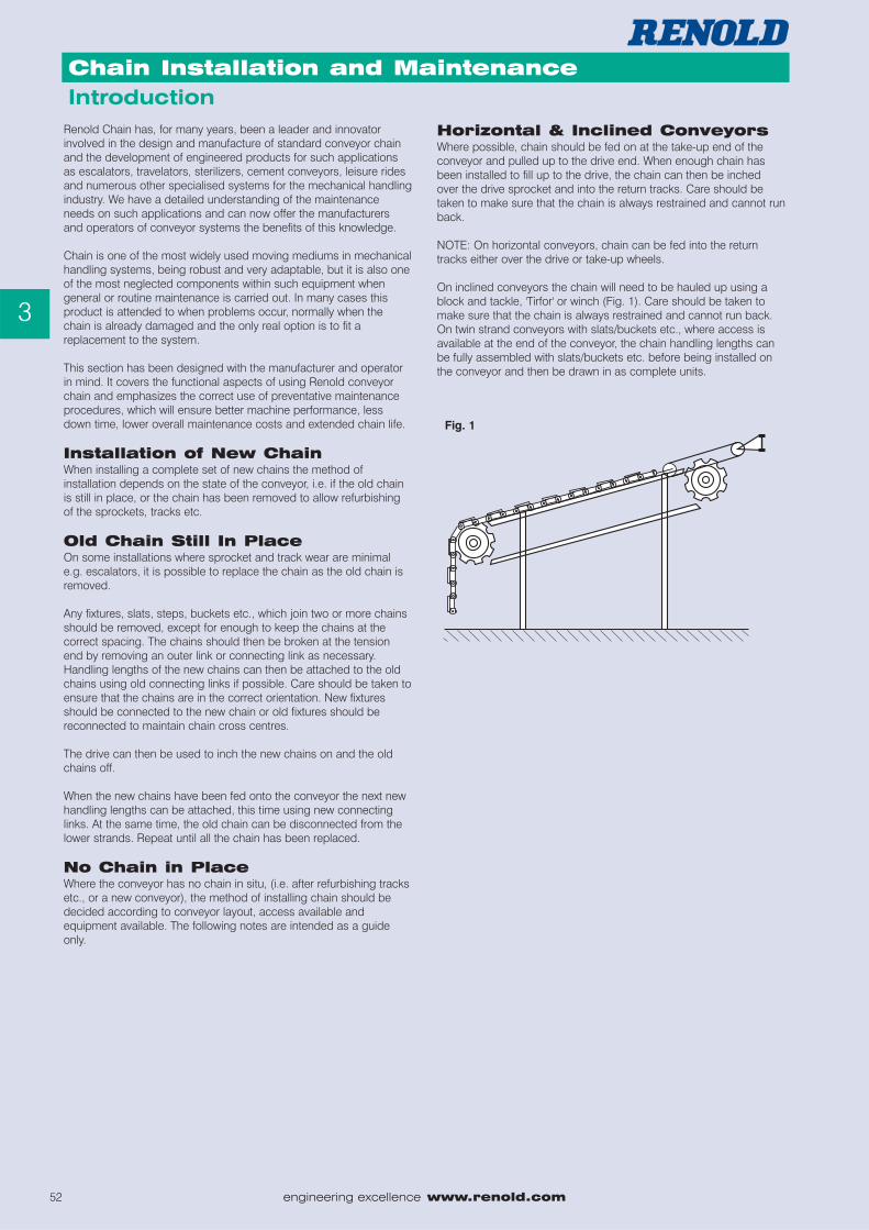
On inclined conveyors the chain will need to be hauled up using ablock and tackle, 'Tirfor' or winch (Fig. 1). Care should be taken tomake sure that the chain is always restrained and cannot run back.On twin strand conveyors with slats/buckets etc., where access isavailable at the end of the conveyor, the chain handling lengths canbe fully assembled with slats/buckets etc. before being installed onthe conveyor and then be drawn in as complete units.
Fig. 1
www.renold.com engineering excellence 53
Agricultural Chain
3
Chain Installation and Maintenance
Bucket ElevatorsOn light duty elevators it may be possible, if access and space areavailable, to install the chain from the top of the elevator and join thechain at the drive sprocket.
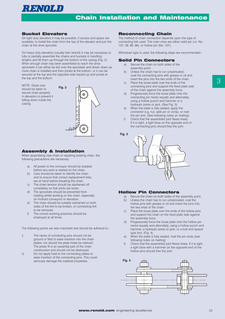
On heavy duty elevators (usually twin strand) it may be necessary tofully or partially assemble the chains and buckets in handlinglengths and lift them up through the bottom of the casing (Fig. 2).When enough chain has been assembled to reach the drivesprockets it can either be fed over the sprockets and driven down asmore chain is installed and then joined at the bottom, or it can besecured at the top and the opposite side hauled up and joined atthe top and the bottom.
NOTE: Great careshould be taken tosecure chain properlyin elevators to prevent itfalling down inside thecasing.
Assembly & InstallationWhen assembling new chain or repairing existing chain, thefollowing precautions are necessary.
a) All power to the conveyor should be isolatedbefore any work is started on the chain.
b) Care should be taken to identify the chainand to ensure that correct replacement linksare at hand before breaking the chain.
c) The chain tension should be slackened off completely so that joints are loose.
d) The sprockets should be prevented fromrotating whilst working on the chain, especiallyon inclined conveyors or elevators.
e) The chain should be suitably restrained on bothsides of the link to be broken, or connecting linkto be removed.
f) The correct working practices should beemployed at all times.
The following points are also important and should be adhered to:-
i) The necks of connecting pins should not be ground or filed to ease insertion into the chain plates, nor should the plate holes be relieved. The press fit is an essential part of the chain construction and should not be destroyed.
ii) Do not apply heat to the connecting plates to ease insertion of the connecting pins. This could seriously damage the material properties.
Reconnecting ChainThe method of chain connection depends upon the type ofconnecting link used. The main ones are either solid pin (i.e. No.107, 58, 69, 86), or hollow pin (No. 107).
Whichever type is used, the following steps are recommended:-
Solid Pin Connectorsa) Secure the chain on both sides of the
assembly point.b) Unless the chain has to run unlubricated,
coat the connecting pins with grease or oil and insert the pins into the two ends of the chain.
c) Place the loose plate over the ends of the connecting pins and support the fixed plate sideof the chain against the assembly force.
d) Progressively force the loose plate onto the connecting pin necks equally and alternately, using a hollow punch and hammer or a hydraulic press or jack. (See Fig. 3).
e) When the plate is fully seated, apply the connector e.g. nut, split pin or circlip, or rivet the pin end. (See following notes on riveting).
f) Check that the assembled joint flexes freely. If it is tight, a light blow on the opposite end of the connecting pins should free the joint.
Hollow Pin Connectorsa) Secure the chain on both sides of the assembly point.b) Unless the chain has to run unlubricated, coat the
hollow pins with grease or oil and insert the pins into the two ends of the chain.
c) Place the loose plate over the ends of the hollow pins and support the chain on the fixed plate side against the assembly force.
d) Progressively force the loose plate onto the hollow pin necks equally and alternately, using a hollow punch and hammer, a hydraulic press or jack, or a bolt and spacer type tool. (Fig. 4).
e) When the plate is fully seated, rivet the pin ends (see following notes on riveting).
f) Check that the assembled joint flexes freely. If it is tight, a light blow with a hammer on the opposite end of the hollow pins should free the joint.
Fig. 2
Fig. 3
Fig. 4
54 engineering excellence www.renold.com
Agricultural Chain
3
Chain Installation and Maintenance
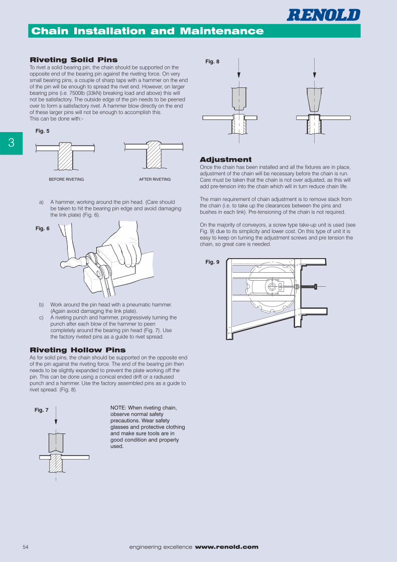
Riveting Solid PinsTo rivet a solid bearing pin, the chain should be supported on theopposite end of the bearing pin against the riveting force. On verysmall bearing pins, a couple of sharp taps with a hammer on the endof the pin will be enough to spread the rivet end. However, on largerbearing pins (i.e. 7500lb (33kN) breaking load and above) this willnot be satisfactory. The outside edge of the pin needs to be peenedover to form a satisfactory rivet. A hammer blow directly on the endof these larger pins will not be enough to accomplish this.This can be done with:-
a) A hammer, working around the pin head. (Care should be taken to hit the bearing pin edge and avoid damaging the link plate) (Fig. 6).
b) Work around the pin head with a pneumatic hammer. (Again avoid damaging the link plate).
c) A riveting punch and hammer, progressively turning the punch after each blow of the hammer to peen completely around the bearing pin head (Fig. 7). Use the factory riveted pins as a guide to rivet spread.
Riveting Hollow PinsAs for solid pins, the chain should be supported on the opposite endof the pin against the riveting force. The end of the bearing pin thenneeds to be slightly expanded to prevent the plate working off thepin. This can be done using a conical ended drift or a radiusedpunch and a hammer. Use the factory assembled pins as a guide torivet spread. (Fig. 8).
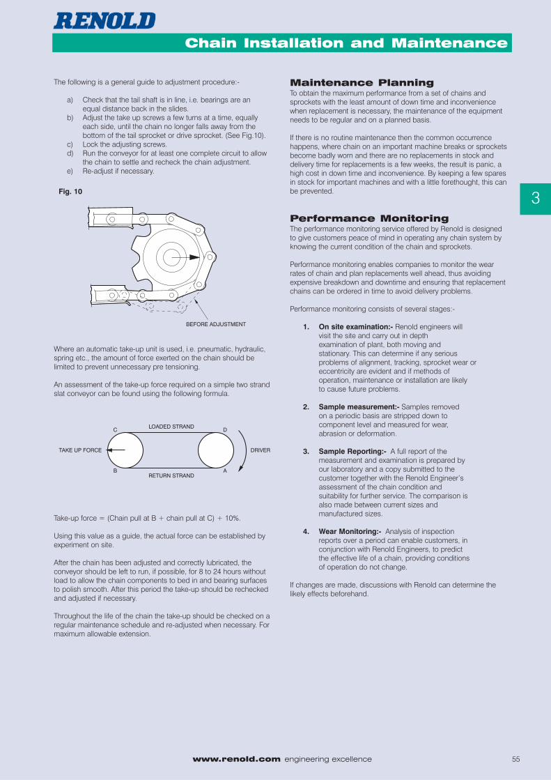
AdjustmentOnce the chain has been installed and all the fixtures are in place,adjustment of the chain will be necessary before the chain is run.Care must be taken that the chain is not over adjusted, as this willadd pre-tension into the chain which will in turn reduce chain life.
The main requirement of chain adjustment is to remove slack fromthe chain (i.e. to take up the clearances between the pins andbushes in each link). Pre-tensioning of the chain is not required.
On the majority of conveyors, a screw type take-up unit is used (seeFig. 9) due to its simplicity and lower cost. On this type of unit it iseasy to keep on turning the adjustment screws and pre tension thechain, so great care is needed.
NOTE: When riveting chain,observe normal safetyprecautions. Wear safetyglasses and protective clothingand make sure tools are ingood condition and properlyused.
Fig. 7
Fig. 9
Fig. 8
Fig. 6
Fig. 5
www.renold.com engineering excellence 55
Agricultural Chain
3
Chain Installation and Maintenance
The following is a general guide to adjustment procedure:-
a) Check that the tail shaft is in line, i.e. bearings are an equal distance back in the slides.
b) Adjust the take up screws a few turns at a time, equally each side, until the chain no longer falls away from the bottom of the tail sprocket or drive sprocket. (See Fig.10).
c) Lock the adjusting screws.d) Run the conveyor for at least one complete circuit to allow
the chain to settle and recheck the chain adjustment.e) Re-adjust if necessary.
Where an automatic take-up unit is used, i.e. pneumatic, hydraulic,spring etc., the amount of force exerted on the chain should belimited to prevent unnecessary pre tensioning.
An assessment of the take-up force required on a simple two strandslat conveyor can be found using the following formula.
Take-up force = (Chain pull at B + chain pull at C) + 10%.
Using this value as a guide, the actual force can be established byexperiment on site.
After the chain has been adjusted and correctly lubricated, theconveyor should be left to run, if possible, for 8 to 24 hours withoutload to allow the chain components to bed in and bearing surfacesto polish smooth. After this period the take-up should be recheckedand adjusted if necessary.
Throughout the life of the chain the take-up should be checked on aregular maintenance schedule and re-adjusted when necessary. Formaximum allowable extension.
Maintenance PlanningTo obtain the maximum performance from a set of chains andsprockets with the least amount of down time and inconveniencewhen replacement is necessary, the maintenance of the equipmentneeds to be regular and on a planned basis.
If there is no routine maintenance then the common occurrencehappens, where chain on an important machine breaks or sprocketsbecome badly worn and there are no replacements in stock anddelivery time for replacements is a few weeks, the result is panic, ahigh cost in down time and inconvenience. By keeping a few sparesin stock for important machines and with a little forethought, this canbe prevented.
Performance MonitoringThe performance monitoring service offered by Renold is designedto give customers peace of mind in operating any chain system byknowing the current condition of the chain and sprockets.
Performance monitoring enables companies to monitor the wearrates of chain and plan replacements well ahead, thus avoidingexpensive breakdown and downtime and ensuring that replacementchains can be ordered in time to avoid delivery problems.
Performance monitoring consists of several stages:-
1. On site examination:- Renold engineers will visit the site and carry out in depth examination of plant, both moving and stationary. This can determine if any serious problems of alignment, tracking, sprocket wear or eccentricity are evident and if methods of operation, maintenance or installation are likely to cause future problems.
2. Sample measurement:- Samples removed on a periodic basis are stripped down to component level and measured for wear, abrasion or deformation.
3. Sample Reporting:- A full report of the measurement and examination is prepared by our laboratory and a copy submitted to the customer together with the Renold Engineer’s assessment of the chain condition and suitability for further service. The comparison isalso made between current sizes and manufactured sizes.
4. Wear Monitoring:- Analysis of inspection reports over a period can enable customers, in conjunction with Renold Engineers, to predict the effective life of a chain, providing conditions of operation do not change.
If changes are made, discussions with Renold can determine thelikely effects beforehand.
Fig. 10
56 engineering excellence www.renold.com
Agricultural Chain
3
Chain Installation and MaintenanceMaintenance Schedule
A typical maintenance schedule is laid out below. This should beadapted to suit each specific application, based on the localconditions and duty cycle.
Typical Maintenance Schedule
EVERY WEEK
� Check lubrication and lubricate if necessary.
FIRST MONTH'S RUNNING
� Check chain take-up and adjust if necessary.
� Check for unusual wear and identify cause and rectify.
EVERY 3 MONTHS
� Check chain take-up and adjust if necessary.
� Check unusual wear and identify cause and rectify.
AFTER 3 MONTHS
� Check chain adjustment and rectify if necessary.
� Change oil, oil filter and clear the sump, if lubrication system fitted
ANNUALLY
� Carry out the above checks.
� Check for wear on side plates.
� Check for chain elongation.
� Check cleanliness of components.- Remove any accumulation of dirt or foreign materials.
� Check for shaft and sprocket alignment.
� Check for wear on sprockets.
� Check the condition of the lubricant.
� Check the lubrication system.
LubricationEffective lubrication of the chain bearing surfaces is essential toobtain optimum performance in addition to minimising powerabsorption, rate of wear, probability of corrosion and noise.
For normal conditions a good quality mineral oil with mediumviscosity, for example SAE 20W50, is recommended where operatingtemperatures are normal.
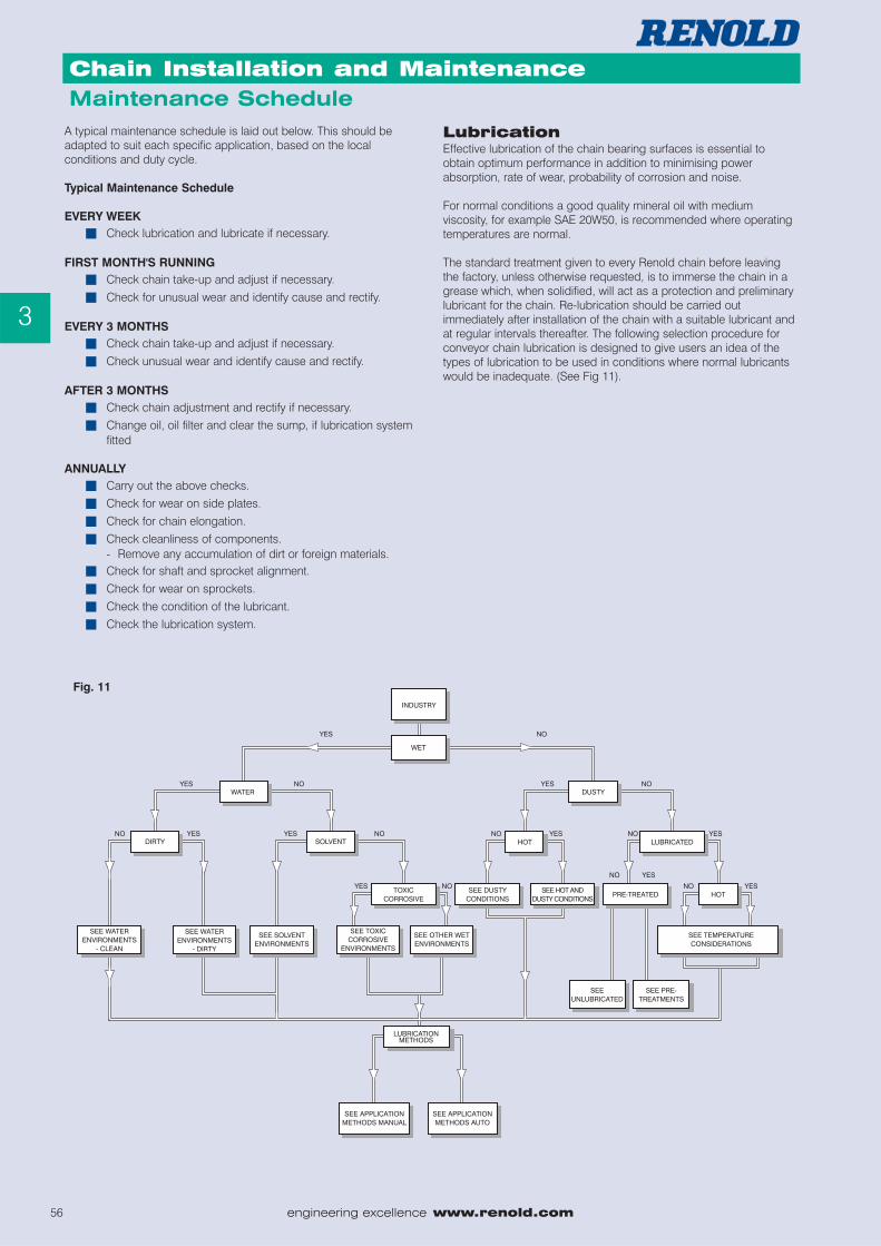
The standard treatment given to every Renold chain before leavingthe factory, unless otherwise requested, is to immerse the chain in agrease which, when solidified, will act as a protection and preliminarylubricant for the chain. Re-lubrication should be carried outimmediately after installation of the chain with a suitable lubricant andat regular intervals thereafter. The following selection procedure forconveyor chain lubrication is designed to give users an idea of thetypes of lubrication to be used in conditions where normal lubricantswould be inadequate. (See Fig 11).
Fig. 11

www.renold.com engineering excellence 57
Agricultural Chain
3
Chain Installation and Maintenance
Industry
Some industries will have special needs from aselected lubricant. These needs will usually bedetermined by the demands of the producthandled and the product susceptibility tocontamination and spoiling by direct or indirectcontact with lubricant. Some industries with
these special needs are listed and users should contact lubricantspecialists for recommendations.
Marine Industry TobaccoCeramics SugarTextiles Hospital EquipmentFood Industry Nuclear EnvironmentWater
Temperature Considerations
Low temperature conditions -60°C to 0°C,require application of low temperature, waterrepellent grease to lubricate and preventcondensation water freezing and locking thechain. Low temperature lubricants are designedto be both lubricants and water repellents. Theycomprise synthetic oils in an organic or
inorganic carrier. Lubrication is by means of synthetic polymerswhich, under load, form chains to provide a passive film on frictionsurfaces. They will not mix with, and actively repel, water.Temperature range -60°C to +120°C.
High temperature 100°C to 450°C.
Up to 160°C a wet film lubricant is generally used. Above 160°C asuitable dry-film, non-carbonising lubricant is generally employed.
Wet-film, high temperature lubricants are usually solid lubricants(greases), which are dispersed in a chlorinated hydrocarbon solvent.This allows penetration of lubricant into critical areas, after whichsolvent evaporation occurs. (Temperature range -25°C to + 160°C).
Dry-film, high temperature lubricants usually consist of colloidalmolybdenum disulphide or graphite in a non-carbonising syntheticcarrier. This carrier penetrates into the critical areas of the chain andthen evaporates, leaving a dry MoS2 or graphite film. (Temperaturerange 0° to + 450°C).
Dusty Conditions
Chain should be prelubricated before operationwith a suitable dry film lubricant to prevent dustadhering to the lubricant. Periodically the chainshould be cleaned and re-lubricated with thesame lubricant.
Chains fitted with grease gun lubricated pins and bushes are mosteffective in these environments.
Hot and Dusty Conditions
The same considerations should be usedas for dusty conditions, but the dry filmlubricant should be chosen to be effectiveat the operating temperature.
Water Environments-Clean
In water plants, chains are usually operatingabove water level and therefore requirelubricants that are effective, but sufficientlyadhesive to not fall into potential drinking water.Lubricants are available as special heavygreases and these are most effective whenapplied to the chain components during chain
assembly. Water industry grease comprises a blend of mineral oil,graphite, hydrophobic and anti-corrosive elements. Each in its turnwill lubricate, repel water and prevent corrosion. The grease will notdilute in water, is extremely adhesive and actively repels water. Thesame heavy duty greases are available for chains operating in waterwhere contamination is not a problem. Regular regreasing isnecessary in this case. Water authority approval may be required forlubricants used near drinking water.
Water Environments - Dirty
Chains operating in sewage treatment worksare frequently completely immersed and, otherthan a prelubrication, it is impossible to lubricateregularly. In these cases, chains are selected tooperate sacrificially, or special materials areselected to operate in a continuously wetenvironment. Where chains are accessible for
lubrication, grease gun lubricated chains should be used with waterrepellent grease to periodically flush out the old grease andcontaminants.
Solvent Environments
Where chains are operating in a solventatmosphere, then lubricants must be chosenwith great care. Regular re-lubrication is usuallynot possible due to removal of lubricant by thesolvent, causing solvent (and therefore product)contamination. Lubrication suppliers should beconsulted and a product obtained that will notbe dissolved by the solvent.
Other Wet Environments
These special environments must be individuallyconsidered. Consult specialist lubricant supplieror contact Renold.
58 engineering excellence www.renold.com
Agricultural Chain
3
Chain Installation and Maintenance
9. Toxic or Corrosive Environments
Specialist lubricants must be obtained for theseconditions and selection will depend upon thematerial being handled. Consult specialistlubricant supplier or contact Renold.
10. Application Methods
Manual. By oil can, brush or aerosol, applieddirectly on the chain. Automatic. By drip feed,preferably one shot lubrication which depositsthe correct amount of lubricant at the correcttime in the correct place on the chain. It isimperative that lubrication is accurately applied.Too much lubricant is as harmful as too little.
Incorrect application of lubricant will result in irregular motion of thechain, particularly at low speed or light loads due to “stick slip”.
11. Pre Treatments
The following pre treatments can be appliedduring the manufacture of chain componentsand the advantages are listed. Phosphating.The application of a manganese phosphatecoating to pin and bush surfaces. The surfacegives a small degree of pre-lubrication, but itsmain advantage is to provide a key for
subsequent lubrication and makes this much more effective andresilient. Molybdenum Disulphide. A coating applied to pins andbushes during manufacture by dipping, followed by oven curing.Lowers friction between components and acts as preliminarylubricant. The film is only a few microns thick and is eroded inabrasive conditions. PTFE. Coating applied as above, with verysimilar characteristics.
12. Unlubricated
Some environments preclude the use of anytype of lubrication or precoating, due either toproduct contamination or the possibility ofcreating volatile compounds or grinding pastes.In these cases, chain life will be improved byperiodic cleaning or washing to remove materials built up over the chain.
Compressed air can sometimes be recommended should materialbe loose and light in mass.
Lubricant Application Methods
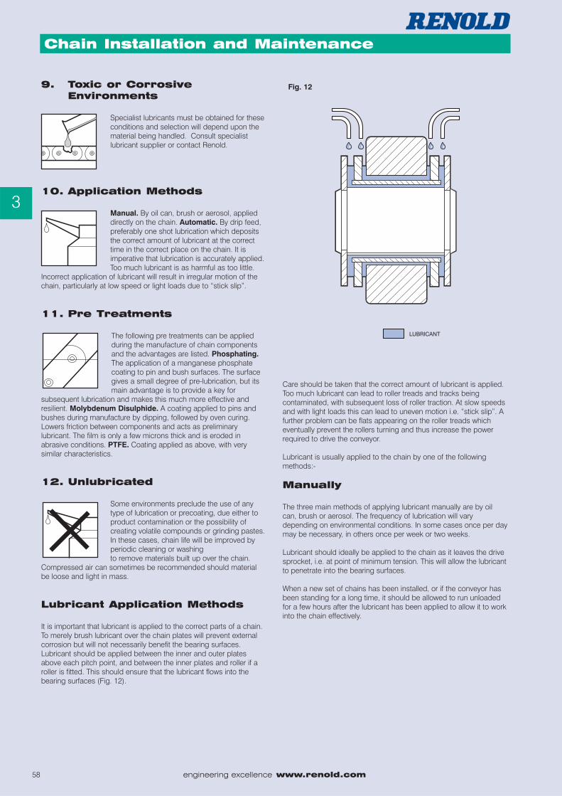
It is important that lubricant is applied to the correct parts of a chain.To merely brush lubricant over the chain plates will prevent externalcorrosion but will not necessarily benefit the bearing surfaces.Lubricant should be applied between the inner and outer platesabove each pitch point, and between the inner plates and roller if aroller is fitted. This should ensure that the lubricant flows into thebearing surfaces (Fig. 12).
Care should be taken that the correct amount of lubricant is applied.Too much lubricant can lead to roller treads and tracks beingcontaminated, with subsequent loss of roller traction. At slow speedsand with light loads this can lead to uneven motion i.e. “stick slip”. Afurther problem can be flats appearing on the roller treads whicheventually prevent the rollers turning and thus increase the powerrequired to drive the conveyor.
Lubricant is usually applied to the chain by one of the followingmethods:-
Manually
The three main methods of applying lubricant manually are by oilcan, brush or aerosol. The frequency of lubrication will varydepending on environmental conditions. In some cases once per daymay be necessary, in others once per week or two weeks.
Lubricant should ideally be applied to the chain as it leaves the drivesprocket, i.e. at point of minimum tension. This will allow the lubricantto penetrate into the bearing surfaces.
When a new set of chains has been installed, or if the conveyor hasbeen standing for a long time, it should be allowed to run unloadedfor a few hours after the lubricant has been applied to allow it to workinto the chain effectively.
Fig. 12
www.renold.com engineering excellence 59
Agricultural Chain
3
Chain Installation and Maintenance
Auto-LubThe main types of auto-lub systems are drip feed, single shot and oilmist spray. All systems consist of a fixed set of pipes, an oil reservoirand the necessary control valves and pumps. The purpose of thesystem is to automatically deposit an amount of oil in the chain as itpasses the oil discharge point. Drip feed systems are usually gravityfed, but the single shot and oil mist spray are usually pneumatic.
The system should be switched on once per day, once per week, orhowever necessary for one or two complete circuits of the chain toensure the bearing surfaces are satisfactorily lubricated. Unless theconveyor is part of a process where the lubricant is continually beingwashed off the chain, the lubricator should not be run continually.
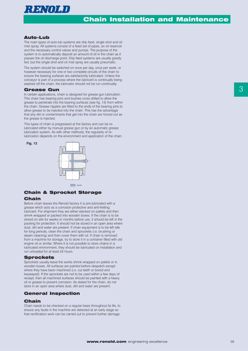
Grease GunIn certain applications, chain is designed for grease gun lubrication.This chain has bearing pins and bushes cross drilled to allow thegrease to penetrate into the bearing surfaces (see fig. 13) from withinthe chain. Grease nipples are fitted to the ends of the bearing pins toallow grease to be injected into the chain. This has the advantagethat any dirt or contaminants that get into the chain are forced out asthe grease is injected.
This types of chain is pregreased at the factory and can be re-lubricated either by manual grease gun or by an automatic greaselubrication system. As with other methods, the regularity of re-lubrication depends on the environment and application of the chain.
Chain & Sprocket Storage
ChainBefore chain leaves the Renold factory it is pre-lubricated with agrease which acts as a corrosion protective and anti-frettinglubricant. For shipment they are either stacked on pallets and thenshrink wrapped or packed into wooden boxes. If the chain is to bestored on site for weeks or months before use, it should be left in thepacking for protection. It should not be stored in an open area wheredust, dirt and water are present. If chain equipment is to be left idlefor long periods, clean the chain and sprockets (i.e. brushing orsteam cleaning) and then cover them with oil. If chain is removedfrom a machine for storage, try to store it in a container filled with oldengine oil or similar. Where it is not possible to store chains in alubricated environment, they should be lubricated on installation andrun unloaded for at least 24 hours.
SprocketsSprockets usually leave the works shrink wrapped on pallets or inwooden boxes. All surfaces are painted before despatch exceptwhere they have been machined (i.e. cut teeth or bored andkeywayed). If the sprockets are not to be used within a few days ofreceipt, then all machined surfaces should be painted with a heavyoil or grease to prevent corrosion. As stated for the chain, do notstore in an open area where dust, dirt and water are present.
General Inspection
ChainChain needs to be checked on a regular basis throughout its life, toensure any faults in the machine are detected at an early stage sothat rectification work can be carried out to prevent further damage.
Fig. 13
60 engineering excellence www.renold.com
Agricultural Chain
3
Chain Installation and Maintenance
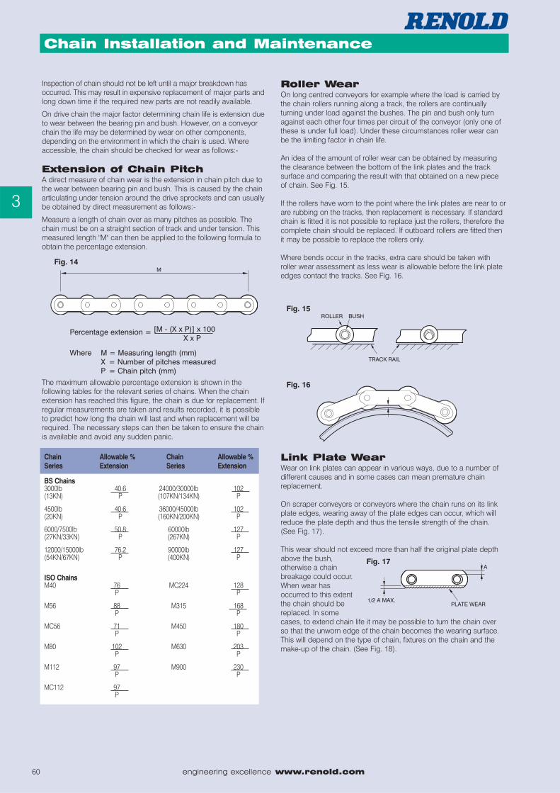
Where M = Measuring length (mm)X = Number of pitches measuredP = Chain pitch (mm)
Percentage extension = [M - (X x P)] x 100X x P
Fig. 15
Fig. 16
Inspection of chain should not be left until a major breakdown hasoccurred. This may result in expensive replacement of major parts andlong down time if the required new parts are not readily available.
On drive chain the major factor determining chain life is extension dueto wear between the bearing pin and bush. However, on a conveyorchain the life may be determined by wear on other components,depending on the environment in which the chain is used. Whereaccessible, the chain should be checked for wear as follows:-
Extension of Chain PitchA direct measure of chain wear is the extension in chain pitch due tothe wear between bearing pin and bush. This is caused by the chainarticulating under tension around the drive sprockets and can usuallybe obtained by direct measurement as follows:-
Measure a length of chain over as many pitches as possible. Thechain must be on a straight section of track and under tension. Thismeasured length "M" can then be applied to the following formula toobtain the percentage extension.
The maximum allowable percentage extension is shown in thefollowing tables for the relevant series of chains. When the chainextension has reached this figure, the chain is due for replacement. Ifregular measurements are taken and results recorded, it is possibleto predict how long the chain will last and when replacement will berequired. The necessary steps can then be taken to ensure the chainis available and avoid any sudden panic.
Roller WearOn long centred conveyors for example where the load is carried bythe chain rollers running along a track, the rollers are continuallyturning under load against the bushes. The pin and bush only turnagainst each other four times per circuit of the conveyor (only one ofthese is under full load). Under these circumstances roller wear canbe the limiting factor in chain life.
An idea of the amount of roller wear can be obtained by measuringthe clearance between the bottom of the link plates and the tracksurface and comparing the result with that obtained on a new pieceof chain. See Fig. 15.
If the rollers have worn to the point where the link plates are near to orare rubbing on the tracks, then replacement is necessary. If standardchain is fitted it is not possible to replace just the rollers, therefore thecomplete chain should be replaced. If outboard rollers are fitted thenit may be possible to replace the rollers only.
Where bends occur in the tracks, extra care should be taken withroller wear assessment as less wear is allowable before the link plateedges contact the tracks. See Fig. 16.
Link Plate WearWear on link plates can appear in various ways, due to a number ofdifferent causes and in some cases can mean premature chainreplacement.
On scraper conveyors or conveyors where the chain runs on its linkplate edges, wearing away of the plate edges can occur, which willreduce the plate depth and thus the tensile strength of the chain.(See Fig. 17).
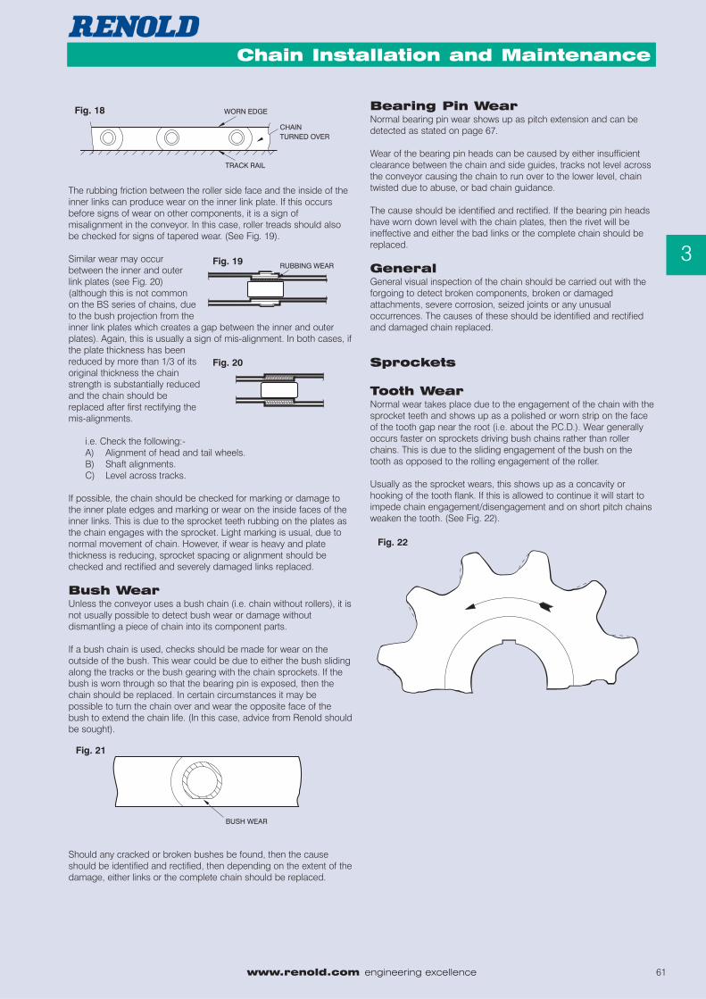
This wear should not exceed more than half the original plate depthabove the bush,otherwise a chainbreakage could occur.When wear hasoccurred to this extentthe chain should bereplaced. In somecases, to extend chain life it may be possible to turn the chain overso that the unworn edge of the chain becomes the wearing surface.This will depend on the type of chain, fixtures on the chain and themake-up of the chain. (See Fig. 18).
Fig. 14
Fig. 17
Chain Allowable % Chain Allowable %Series Extension Series Extension
BS Chains3000lb 40.6 24000/30000lb 102(13KN) P (107KN/134KN) P
4500lb 40.6 36000/45000lb 102(20KN) P (160KN/200KN) P
6000/7500lb 50.8 60000lb 127(27KN/33KN) P (267KN) P
12000/15000lb 76.2 90000lb 127(54KN/67KN) P (400KN) P
ISO ChainsM40 76 MC224 128
P P
M56 88 M315 168P P
MC56 71 M450 180P P
M80 102 M630 203P P
M112 97 M900 230P P
MC112 97P
www.renold.com engineering excellence 61
Agricultural Chain
3
Chain Installation and Maintenance
The rubbing friction between the roller side face and the inside of theinner links can produce wear on the inner link plate. If this occursbefore signs of wear on other components, it is a sign ofmisalignment in the conveyor. In this case, roller treads should alsobe checked for signs of tapered wear. (See Fig. 19).
Similar wear may occurbetween the inner and outerlink plates (see Fig. 20)(although this is not commonon the BS series of chains, dueto the bush projection from theinner link plates which creates a gap between the inner and outerplates). Again, this is usually a sign of mis-alignment. In both cases, ifthe plate thickness has beenreduced by more than 1/3 of itsoriginal thickness the chainstrength is substantially reducedand the chain should bereplaced after first rectifying themis-alignments.
i.e. Check the following:-A) Alignment of head and tail wheels.B) Shaft alignments.C) Level across tracks.
If possible, the chain should be checked for marking or damage tothe inner plate edges and marking or wear on the inside faces of theinner links. This is due to the sprocket teeth rubbing on the plates asthe chain engages with the sprocket. Light marking is usual, due tonormal movement of chain. However, if wear is heavy and platethickness is reducing, sprocket spacing or alignment should bechecked and rectified and severely damaged links replaced.
Bush WearUnless the conveyor uses a bush chain (i.e. chain without rollers), it isnot usually possible to detect bush wear or damage withoutdismantling a piece of chain into its component parts.
If a bush chain is used, checks should be made for wear on theoutside of the bush. This wear could be due to either the bush slidingalong the tracks or the bush gearing with the chain sprockets. If thebush is worn through so that the bearing pin is exposed, then thechain should be replaced. In certain circumstances it may bepossible to turn the chain over and wear the opposite face of thebush to extend the chain life. (In this case, advice from Renold shouldbe sought).
Should any cracked or broken bushes be found, then the causeshould be identified and rectified, then depending on the extent of thedamage, either links or the complete chain should be replaced.
Bearing Pin WearNormal bearing pin wear shows up as pitch extension and can bedetected as stated on page 67.
Wear of the bearing pin heads can be caused by either insufficientclearance between the chain and side guides, tracks not level acrossthe conveyor causing the chain to run over to the lower level, chaintwisted due to abuse, or bad chain guidance.
The cause should be identified and rectified. If the bearing pin headshave worn down level with the chain plates, then the rivet will beineffective and either the bad links or the complete chain should bereplaced.
GeneralGeneral visual inspection of the chain should be carried out with theforgoing to detect broken components, broken or damagedattachments, severe corrosion, seized joints or any unusualoccurrences. The causes of these should be identified and rectifiedand damaged chain replaced.
Sprockets
Tooth WearNormal wear takes place due to the engagement of the chain with thesprocket teeth and shows up as a polished or worn strip on the faceof the tooth gap near the root (i.e. about the P.C.D.). Wear generallyoccurs faster on sprockets driving bush chains rather than rollerchains. This is due to the sliding engagement of the bush on thetooth as opposed to the rolling engagement of the roller.
Usually as the sprocket wears, this shows up as a concavity orhooking of the tooth flank. If this is allowed to continue it will start toimpede chain engagement/disengagement and on short pitch chainsweaken the tooth. (See Fig. 22).
Fig. 18
Fig. 20
Fig. 21
Fig. 22
Fig. 19
62 engineering excellence www.renold.com
Agricultural Chain
3
Chain Installation and Maintenance
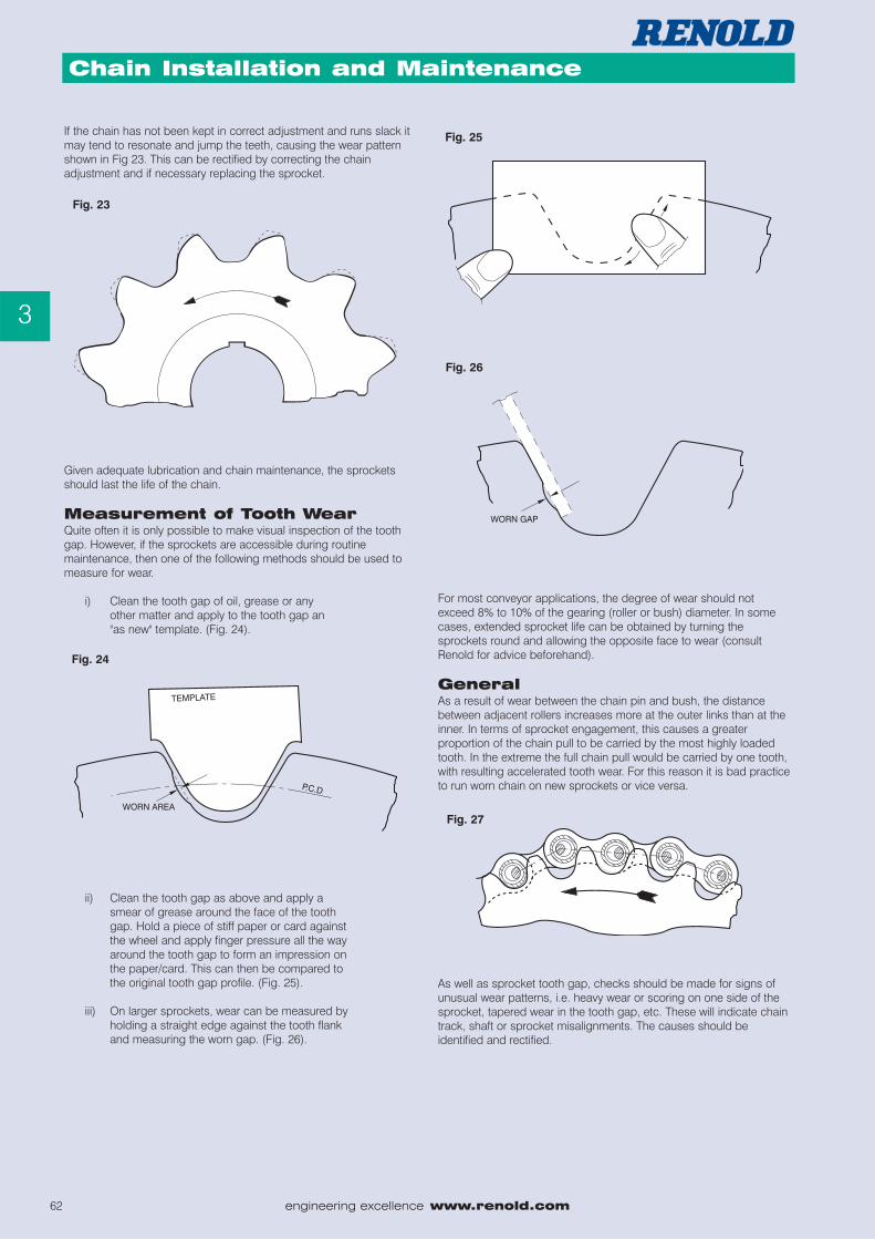
If the chain has not been kept in correct adjustment and runs slack itmay tend to resonate and jump the teeth, causing the wear patternshown in Fig 23. This can be rectified by correcting the chainadjustment and if necessary replacing the sprocket.
Given adequate lubrication and chain maintenance, the sprocketsshould last the life of the chain.
Measurement of Tooth WearQuite often it is only possible to make visual inspection of the toothgap. However, if the sprockets are accessible during routinemaintenance, then one of the following methods should be used tomeasure for wear.
i) Clean the tooth gap of oil, grease or anyother matter and apply to the tooth gap an"as new" template. (Fig. 24).
ii) Clean the tooth gap as above and apply asmear of grease around the face of the toothgap. Hold a piece of stiff paper or card againstthe wheel and apply finger pressure all the wayaround the tooth gap to form an impression onthe paper/card. This can then be compared tothe original tooth gap profile. (Fig. 25).
iii) On larger sprockets, wear can be measured byholding a straight edge against the tooth flankand measuring the worn gap. (Fig. 26).
For most conveyor applications, the degree of wear should notexceed 8% to 10% of the gearing (roller or bush) diameter. In somecases, extended sprocket life can be obtained by turning thesprockets round and allowing the opposite face to wear (consultRenold for advice beforehand).
GeneralAs a result of wear between the chain pin and bush, the distancebetween adjacent rollers increases more at the outer links than at theinner. In terms of sprocket engagement, this causes a greaterproportion of the chain pull to be carried by the most highly loadedtooth. In the extreme the full chain pull would be carried by one tooth,with resulting accelerated tooth wear. For this reason it is bad practiceto run worn chain on new sprockets or vice versa.
As well as sprocket tooth gap, checks should be made for signs ofunusual wear patterns, i.e. heavy wear or scoring on one side of thesprocket, tapered wear in the tooth gap, etc. These will indicate chaintrack, shaft or sprocket misalignments. The causes should beidentified and rectified.
Fig. 23
Fig. 24
Fig. 27
Fig. 26
Fig. 25
www.renold.com engineering excellence 63
Agricultural Chain
3
Chain Installation and Maintenance
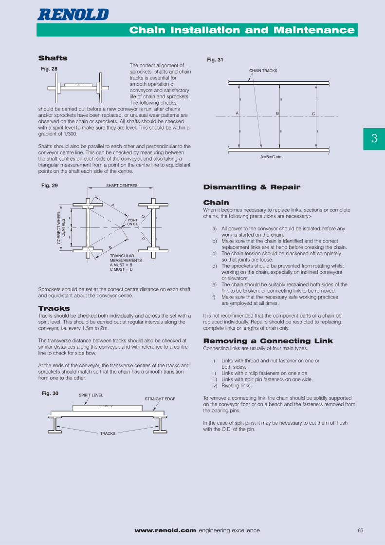
ShaftsThe correct alignment ofsprockets, shafts and chaintracks is essential forsmooth operation ofconveyors and satisfactorylife of chain and sprockets.The following checks
should be carried out before a new conveyor is run, after chainsand/or sprockets have been replaced, or unusual wear patterns areobserved on the chain or sprockets. All shafts should be checkedwith a spirit level to make sure they are level. This should be within agradient of 1/300.
Shafts should also be parallel to each other and perpendicular to theconveyor centre line. This can be checked by measuring betweenthe shaft centres on each side of the conveyor, and also taking atriangular measurement from a point on the centre line to equidistantpoints on the shaft each side of the centre.
Sprockets should be set at the correct centre distance on each shaftand equidistant about the conveyor centre.
TracksTracks should be checked both individually and across the set with aspirit level. This should be carried out at regular intervals along theconveyor, i.e. every 1.5m to 2m.
The transverse distance between tracks should also be checked atsimilar distances along the conveyor, and with reference to a centreline to check for side bow.
At the ends of the conveyor, the transverse centres of the tracks andsprockets should match so that the chain has a smooth transitionfrom one to the other.
Dismantling & Repair
ChainWhen it becomes necessary to replace links, sections or completechains, the following precautions are necessary:-
a) All power to the conveyor should be isolated before any work is started on the chain.
b) Make sure that the chain is identified and the correct replacement links are at hand before breaking the chain.
c) The chain tension should be slackened off completely so that joints are loose.
d) The sprockets should be prevented from rotating whilst working on the chain, especially on inclined conveyors or elevators.
e) The chain should be suitably restrained both sides of the link to be broken, or connecting link to be removed.
f) Make sure that the necessary safe working practices are employed at all times.
It is not recommended that the component parts of a chain bereplaced individually. Repairs should be restricted to replacingcomplete links or lengths of chain only.
Removing a Connecting LinkConnecting links are usually of four main types.
i) Links with thread and nut fastener on one orboth sides.
ii) Links with circlip fasteners on one side.iii) Links with split pin fasteners on one side.iv) Riveting links.
To remove a connecting link, the chain should be solidly supportedon the conveyor floor or on a bench and the fasteners removed fromthe bearing pins.
In the case of split pins, it may be necessary to cut them off flushwith the O.D. of the pin.
Fig. 28
Fig. 29
Fig. 30
Fig. 31
64 engineering excellence www.renold.com
Agricultural Chain
3
Chain Installation and Maintenance
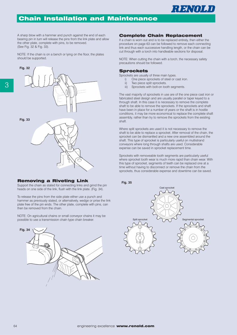
A sharp blow with a hammer and punch against the end of eachbearing pin in turn will release the pins from the link plate and allowthe other plate, complete with pins, to be removed.(See Fig. 32 & Fig. 33).
NOTE: If the chain is on a bench or lying on the floor, the platesshould be supported.
Removing a Riveting LinkSupport the chain as stated for connecting links and grind the pinheads on one side of the link, flush with the link plate. (Fig. 34).
To release the pins from the side plate either use a punch andhammer as previously stated, or alternatively, wedge or prise the linkplate free of the pin ends. The other plate, complete with pins, canthen be removed from the chain.
NOTE: On agricultural chains or small conveyor chains it may bepossible to use a transmission chain type chain breaker.
Complete Chain ReplacementIf a chain is worn out and is to be replaced entirely, then either theprocedure on page 63 can be followed to remove each connectinglink and thus each successive handling length, or the chain can becut through with a torch into handleable sections for disposal.
NOTE: When cutting the chain with a torch, the necessary safetyprecautions should be followed.
SprocketsSprockets are usually of three main types.
i) One piece sprockets of steel or cast iron.ii) Two piece split sprockets.iii) Sprockets with bolt-on tooth segments.
The vast majority of sprockets in use are of the one piece cast iron orfabricated steel design and are usually parallel or taper keyed to athrough shaft. In this case it is necessary to remove the completeshaft to be able to remove the sprockets. If the sprockets and shafthave been in place for a number of years or the shaft is in hostileconditions, it may be more economical to replace the complete shaftassembly, rather than try to remove the sprockets from the existingshaft.
Where split sprockets are used it is not necessary to remove theshaft to be able to replace a sprocket. After removal of the chain, thesprocket can be dismantled and a new one assembled around theshaft. This type of sprocket is particularly useful on multistrandconveyors where long through shafts are used. Considerableexpense can be saved in sprocket replacement time.
Sprockets with removeable tooth segments are particularly usefulwhere sprocket tooth wear is much more rapid than chain wear. Withthis type of sprocket, segments of teeth can be replaced one at atime without having to disconnect or remove the chain from thesprockets, thus considerable expense and downtime can be saved.
Fig. 32
Fig. 33
Fig. 34
Fig. 35
www.renold.com engineering excellence 65
Agricultural Chain
3
Chain Installation and Maintenance
Wear Strips and TracksWear strips and tracks have an important influence on chainperformance and life, as badly aligned or badly worn wear strips cancause abnormal wear on the conveyor chain. Therefore, it isimportant that when replacing chain the wear strips are checked andrenewed if necessary. Running new chain on worn tracks or wearstrips will reduce the life of the chain.
When replacing wear strips, the following should be considered:-
i) It is desirable that the chains are slower wearing than the wear strips as they are the more critical and expensive items in the conveyor.
ii) The wear strips should not be as hard as the chain that is running on it. Bright mild steel flats are satisfactory for most applications. However, under more arduous conditions a harder material can be used.
iii) Wear strips should be flat and level when installed (check with a spirit level). If this is not the case then chain life will be reduced and conveyor operation could be impaired. (See Fig. 30).
iv) Joints in wear strips or tracks should be smooth so that no sharp edges protrude.
v) Weld spatter, slag, metal filings, scale etc. Should be eliminated from the conveyor.
vi) Chain entry and exit points should be radiused to allow smooth transfer of chains from sprockets to tracks.
vii) Non metallic materials such as low friction plastics can be used where chains are sliding on the chain plate edges, but should not be used where severe impact loads or abrasive conditions exist.
Generala) New chains are usually supplied from the factory in
handling lengths and coiled with one loose joining link per length, so that the lengths can be assembled into a complete endless chain. When installing chains the notes on chain reconnection should be followed for joining the handling lengths together.
b) If the chains have been matched, then one end of a handling length will be tagged with a strand letter and connection number (i.e. A3, A4, B3, B4 etc.). Great care should be taken when assembling the chains that like ends are joined (i.e. A2 to A3, B2 to B3 etc.), and also that like numbers are on opposite strands (i.e. A3 opposite B3, A4 opposite B4 etc.). If short lengths are supplied to make the correct number of pitches, these are marked X and Y. The length marked X is assembled on the end of the A chains and the Y on the B chains. Do not remove the tags until the ends are joined correctly.
c) When handling chains, great care should be taken so that the chains do not get a permanent twist or side bow. This will have an adverse affect on chain operation and life.
d) When chains are supplied with attachments as handed strands (i.e. right hand and left hand) make sure that the chains are connected in the correct orientation.
e) Make sure that connecting links are installed with the connector on the correct side of the chain.
Safety Warning
HEALTH AND SAFETY WARNING
1. Always isolate the power source from the drive or equipment.
2. Always wear safety glasses.
3. Always wear appropriate protective clothing, hats, gloves and safety shoes as warranted by the circumstances.
4. Always ensure tools are in good working condition and used in the proper manner.
5. Always loosen tensioning devices.
6. Always support the chain to avoid sudden unexpected movement of chain or components.
7. Never attempt to disconnect or reconnect a chain unless the chain construction is fully understood.
8. Always ensure that directions for the correct use of any tools are followed.
9. Never reuse individual components.
10. Never reuse a damaged chain or chain part.
66 engineering excellence www.renold.com
Agricultural Chain
3
Chain Installation and MaintenanceTroubleshooting
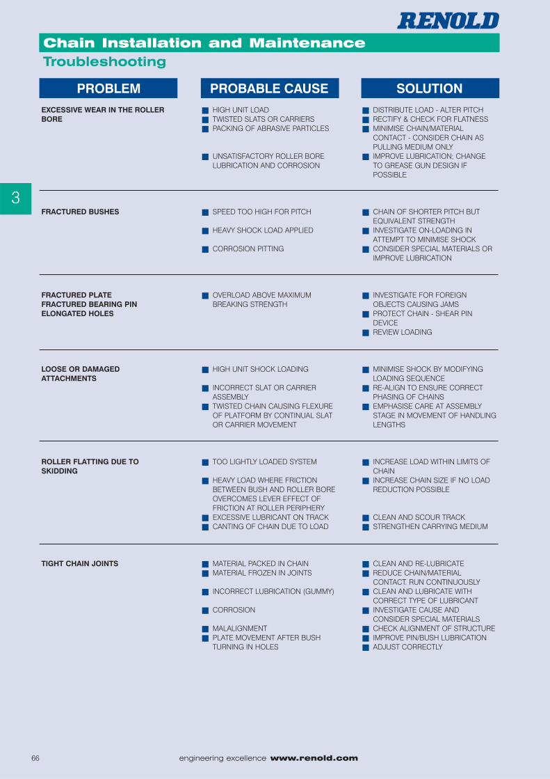
PROBLEMEXCESSIVE WEAR IN THE ROLLERBORE
FRACTURED BUSHES
FRACTURED PLATEFRACTURED BEARING PINELONGATED HOLES
LOOSE OR DAMAGEDATTACHMENTS
ROLLER FLATTING DUE TOSKIDDING
TIGHT CHAIN JOINTS
PROBABLE CAUSE
� HIGH UNIT LOAD� TWISTED SLATS OR CARRIERS� PACKING OF ABRASIVE PARTICLES
� UNSATISFACTORY ROLLER BORE LUBRICATION AND CORROSION
� SPEED TOO HIGH FOR PITCH
� HEAVY SHOCK LOAD APPLIED
� CORROSION PITTING
� OVERLOAD ABOVE MAXIMUM BREAKING STRENGTH
� HIGH UNIT SHOCK LOADING
� INCORRECT SLAT OR CARRIER ASSEMBLY
� TWISTED CHAIN CAUSING FLEXURE OF PLATFORM BY CONTINUAL SLAT OR CARRIER MOVEMENT
� TOO LIGHTLY LOADED SYSTEM
� HEAVY LOAD WHERE FRICTION BETWEEN BUSH AND ROLLER BOREOVERCOMES LEVER EFFECT OF FRICTION AT ROLLER PERIPHERY
� EXCESSIVE LUBRICANT ON TRACK� CANTING OF CHAIN DUE TO LOAD
� MATERIAL PACKED IN CHAIN� MATERIAL FROZEN IN JOINTS
� INCORRECT LUBRICATION (GUMMY)
� CORROSION
� MALALIGNMENT� PLATE MOVEMENT AFTER BUSH
TURNING IN HOLES
SOLUTION
� DISTRIBUTE LOAD - ALTER PITCH� RECTIFY & CHECK FOR FLATNESS� MINIMISE CHAIN/MATERIAL
CONTACT - CONSIDER CHAIN AS PULLING MEDIUM ONLY
� IMPROVE LUBRICATION; CHANGE TO GREASE GUN DESIGN IF POSSIBLE
� CHAIN OF SHORTER PITCH BUT EQUIVALENT STRENGTH
� INVESTIGATE ON-LOADING IN ATTEMPT TO MINIMISE SHOCK
� CONSIDER SPECIAL MATERIALS OR IMPROVE LUBRICATION
� INVESTIGATE FOR FOREIGN OBJECTS CAUSING JAMS
� PROTECT CHAIN - SHEAR PIN DEVICE
� REVIEW LOADING
� MINIMISE SHOCK BY MODIFYING LOADING SEQUENCE
� RE-ALIGN TO ENSURE CORRECT PHASING OF CHAINS
� EMPHASISE CARE AT ASSEMBLY STAGE IN MOVEMENT OF HANDLINGLENGTHS
� INCREASE LOAD WITHIN LIMITS OF CHAIN
� INCREASE CHAIN SIZE IF NO LOAD REDUCTION POSSIBLE
� CLEAN AND SCOUR TRACK� STRENGTHEN CARRYING MEDIUM
� CLEAN AND RE-LUBRICATE� REDUCE CHAIN/MATERIAL
CONTACT. RUN CONTINUOUSLY� CLEAN AND LUBRICATE WITH
CORRECT TYPE OF LUBRICANT� INVESTIGATE CAUSE AND
CONSIDER SPECIAL MATERIALS� CHECK ALIGNMENT OF STRUCTURE� IMPROVE PIN/BUSH LUBRICATION� ADJUST CORRECTLY
www.renold.com engineering excellence 67
Agricultural Chain
3
Chain Installation and MaintenanceTroubleshooting
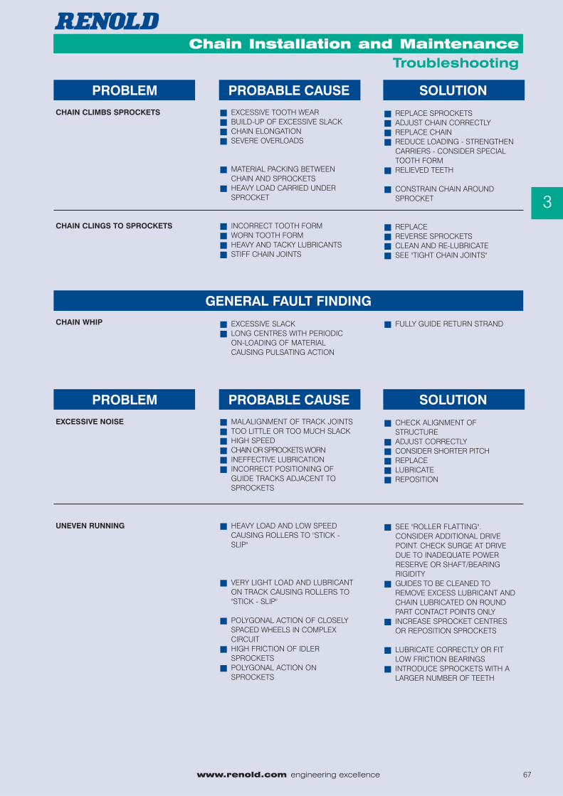
PROBLEMCHAIN CLIMBS SPROCKETS
CHAIN CLINGS TO SPROCKETS
PROBABLE CAUSE
� EXCESSIVE TOOTH WEAR� BUILD-UP OF EXCESSIVE SLACK� CHAIN ELONGATION� SEVERE OVERLOADS
� MATERIAL PACKING BETWEEN CHAIN AND SPROCKETS
� HEAVY LOAD CARRIED UNDER SPROCKET
� INCORRECT TOOTH FORM� WORN TOOTH FORM� HEAVY AND TACKY LUBRICANTS� STIFF CHAIN JOINTS
SOLUTION
� REPLACE SPROCKETS� ADJUST CHAIN CORRECTLY� REPLACE CHAIN� REDUCE LOADING - STRENGTHEN
CARRIERS - CONSIDER SPECIAL TOOTH FORM
� RELIEVED TEETH
� CONSTRAIN CHAIN AROUND SPROCKET
� REPLACE� REVERSE SPROCKETS� CLEAN AND RE-LUBRICATE� SEE "TIGHT CHAIN JOINTS"
PROBLEMEXCESSIVE NOISE
UNEVEN RUNNING
PROBABLE CAUSE
� MALALIGNMENT OF TRACK JOINTS� TOO LITTLE OR TOO MUCH SLACK� HIGH SPEED� CHAIN OR SPROCKETS WORN� INEFFECTIVE LUBRICATION� INCORRECT POSITIONING OF
GUIDE TRACKS ADJACENT TO SPROCKETS
� HEAVY LOAD AND LOW SPEED CAUSING ROLLERS TO "STICK - SLIP"
� VERY LIGHT LOAD AND LUBRICANT ON TRACK CAUSING ROLLERS TO "STICK - SLIP"
� POLYGONAL ACTION OF CLOSELY SPACED WHEELS IN COMPLEX CIRCUIT
� HIGH FRICTION OF IDLER SPROCKETS
� POLYGONAL ACTION ON SPROCKETS
SOLUTION
� CHECK ALIGNMENT OF STRUCTURE
� ADJUST CORRECTLY� CONSIDER SHORTER PITCH� REPLACE� LUBRICATE� REPOSITION
� SEE "ROLLER FLATTING".CONSIDER ADDITIONAL DRIVEPOINT. CHECK SURGE AT DRIVEDUE TO INADEQUATE POWERRESERVE OR SHAFT/BEARINGRIGIDITY
� GUIDES TO BE CLEANED TOREMOVE EXCESS LUBRICANT AND CHAIN LUBRICATED ON ROUND PART CONTACT POINTS ONLY
� INCREASE SPROCKET CENTRES OR REPOSITION SPROCKETS
� LUBRICATE CORRECTLY OR FIT LOW FRICTION BEARINGS
� INTRODUCE SPROCKETS WITH A LARGER NUMBER OF TEETH
GENERAL FAULT FINDINGCHAIN WHIP � EXCESSIVE SLACK
� LONG CENTRES WITH PERIODIC ON-LOADING OF MATERIAL CAUSING PULSATING ACTION
� FULLY GUIDE RETURN STRAND