CONVERTIBLE VERSAJET SERIES SHALLOW … Convertible VersaJet Series is designed for shallow well or...
12
BEFORE YOU START BEFORE INSTALLING PUMP, BE SURE TO READ THIS OWNER’S MANUAL CAREFULLY. REFER TO PRODUCT DATA PLATE(S) FOR ADDITIONAL OPERATING INSTRUCTIONS AND SPECIFICATIONS. Keep work area clean, well-lit and uncluttered. Keep safety labels clean and in good condition. Wear safety glasses while installing or performing maintenance on pump. Adhere to the guidelines of the National Electric Code (NEC) or Canadian Electric Code (CEC), and any other state and local codes for ALL electrical installations. Check with the appropriate agencies or contact a licensed electrician. Most water system problems result from improper installation. It is suggested that you read this manual carefully before installing your pump. The “TROUBLESHOOTING SECTION” will assist you in locating and eliminating the cause of any trouble you may encounter after installation. Check and make available all the tools you will need to install your pump. Required tooling may include wrenches, pipe sealant, pipe fittings and nipples, screwdriver, etc. Be sure to have available proper and adequate wiring material to complete the installation correctly. READ AND FOLLOW SAFETY INSTRUCTIONS This is the safety alert symbol. When you see this symbol on your pump or in this manual, look for one of the following signal words and be alert to the potential for personal injury: WARNING WARNING CAUTION CAUTION WARNING OWNER'S MANUAL CONVERTIBLE VERSAJET SERIES SHALLOW WELL JET PUMP DANGER warns about hazards that will cause serious personal injury, death or major property damage if ignored. WARNING warns about hazards that can cause serious personal injury, death or major property damage if ignored. CAUTION warns about hazards that will or can cause minor personal injury or major property damage if ignored. NOTICE indicates special instructions, which are important but not related to hazards. Carefully read and follow all safety instructions in this manual and on pump. Keep safety labels in good condition. Replace missing or damaged safety labels. HAZARDOUS PRESSURE: Do not run pump against closed discharge. Release all system pressure before working on any component. Do not run pump dry. Fill pump with water before starting or pump will be damaged. The motor on this pump is guaranteed by the manufacturer and in event of failure it must be returned to an authorized service station for repairs. Motor warranty is void if repairs aren’t made by an authorized repair station. NOTICE: If necessary, adjust pressure switch cut- out setting so that pump will not run continuously. Continuous operation at shut-off pressure will damage pump and may damage other system components. ELECTRICAL SAFETY CAUTION Make sure all ELECTRICAL POWER IS OFF before connecting any electrical wires.
Transcript of CONVERTIBLE VERSAJET SERIES SHALLOW … Convertible VersaJet Series is designed for shallow well or...
BEFORE YOU STARTBEFORE INSTALLING PUMP, BE SURE TO READ THIS OWNER’S MANUAL CAREFULLY.
REFER TO PRODUCT DATA PLATE(S) FOR ADDITIONAL OPERATING INSTRUCTIONS AND SPECIFICATIONS.
Keep work area clean, well-lit and uncluttered.
Keep safety labels clean and in good condition.
Wear safety glasses while installing or performing maintenance on pump.
Adhere to the guidelines of the National Electric Code (NEC) or Canadian Electric Code (CEC), and any other state and local codes for ALL electrical installations. Check with the appropriate agencies or contact a licensed electrician.
Most water system problems result from improper installation. It is suggested that you read this manual carefully before installing your pump.
The “TROUBLESHOOTING SECTION” will assist you in locating and eliminating the cause of any trouble you may encounter after installation. Check and make available all the tools you will need to install your pump. Required tooling may include wrenches, pipe sealant, pipe fittings and nipples, screwdriver, etc. Be sure to have available proper and adequate wiring material to complete the installation correctly.
READ AND FOLLOW SAFETY INSTRUCTIONS
This is the safety alert symbol. When you see this symbol on your pump or in this manual, look for one
of the following signal words and be alert to the potential for personal injury:
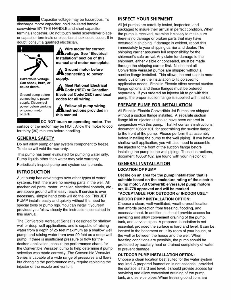
Hazardous voltage.Can shock, burn, orcause death.
Ground pump beforeconnecting to powersupply. Disconnectpower before workingon pump, motor or tank.
WA R N I N GHazardous voltage.Can shock, burn, orcause death.
Ground pump beforeconnecting to powersupply. Disconnectpower before workingon pump, motor or tank.
WA R N I N G
C A U T I O N
C A U T I O N
WARNING
OWNER'S MANUAL
CONVERTIBLE VERSAJET SERIESSHALLOW WELL JET PUMP
D A N G E R warns about hazards that will cause serious personal injury, death or major property damage if ignored.
WARNING warns about hazards that can cause serious personal injury, death or major property damage if ignored.
C A U T I O N warns about hazards that will or can cause minor personal injury or major property damage if ignored.
NOTICE indicates special instructions, which are important but not related to hazards.
Carefully read and follow all safety instructions in this manual and on pump.
Keep safety labels in good condition.
Replace missing or damaged safety labels.
HAZARDOUS PRESSURE: Do not run pump against closed discharge. Release all system pressure before working on any component.
Do not run pump dry. Fill pump with water before starting or pump will be damaged.
The motor on this pump is guaranteed by the manufacturer and in event of failure it must be returned to an authorized service station for repairs. Motor warranty is void if repairs aren’t made by an authorized repair station.
NOTICE: If necessary, adjust pressure switch cut- out setting so that pump will not run
continuously. Continuous operation at shut-off pressure will damage pump and may damage other system components.
ELECTRICAL SAFETYC A U T I O N Make sure all ELECTRICAL POWER IS
OFF before connecting any electrical wires.
WARNING Capacitor voltage may be hazardous. To discharge motor capacitor, hold insulated handle screwdriver BY THE HANDLE and short capacitor terminals together. Do not touch metal screwdriver blade or capacitor terminals or electrical shock could occur. If in doubt, consult a qualified electrician.
Wire motor for correct voltage. See “Electrical
Installation” section of this manual and motor nameplate.
Ground motor before connecting to power
supply.
Meet National Electrical Code (NEC) or Canadian
Electrical Code(CEC) and local codes for all wiring.
Follow all pump wiring instructions provided in
this manual.
C A U T I O N DO NOT touch an operating motor. The surface of the motor may be HOT. Allow the motor to cool for thirty (30) minutes before handling.
GENERAL SAFETYDo not allow pump or any system component to freeze. To do so will void the warranty.
This pump has been evaluated for pumping water only. Pump liquids other than water may void warranty.
Periodically inspect pump and system components.
INTRODUCTIONA jet pump has advantages over other types of water systems. First, there are no moving parts in the well. All mechanical parts, motor, impeller, electrical controls, etc., are above ground within easy reach. If service is ever necessary, simple hand tools will do the job. This JET PUMP installs easily and quickly without the need for special tools or pump rigs. You can install it yourself provided you follow closely the instructions contained in this manual.
The Convertible VersaJet Series is designed for shallow well or deep well applications, and is capable of raising water from a depth of 25 feet maximum as a shallow well pump, and raising water from over 90 feet as a deep well pump. If there is insufficient pressure or flow for the desired application, consult the performance charts for the Convertible VersaJet pump to help determine if pump selection was made correctly. The Convertible VersaJet Series is capable of a wide range of pressures and flows, but changing the performance may require replacing the injector or the nozzle and venturi.
Hazardous voltage.Can shock, burn, orcause death.
Ground pump beforeconnecting to powersupply. Disconnectpower before workingon pump, motor or tank.
WA R N I N G
INSPECT YOUR SHIPMENTAll jet pumps are carefully tested, inspected, and packaged to insure their arrival in perfect condition. When the pump is received, examine it closely to make sure there is no damage or broken parts that may have occurred in shipping. If damage is evident, report this immediately to your shipping carrier and dealer. The shipping carrier assumes full responsibility for the shipment’s safe arrival. Any claim for damage to the shipment, either visible or concealed, must be made through the shipping carrier first. Notice that all Convertible VersaJet pumps are shipped without a suction flange installed. This allows the end-user to more easily customize the installation to fit job specific application needs. Franklin Electric offers several suction flange options, and these flanges must be ordered separately. If you ordered an injector kit to go with this pump, the proper suction flange is supplied with that kit.
PREPARE PUMP FOR INSTALLATIONAll Franklin Electric Convertible Jet Pumps are shipped without a suction flange installed. A separate suction flange kit or injector kit should have been ordered in conjunction with this pump. That kit contains instructions, document 106581101, for assembling the suction flange to the front of the pump. Please perform that assembly before installing the pump to the well piping. If you have a shallow well application, you will also need to assemble the injector to the front of the suction flange before installing the pump to the well piping. Those instructions, document 106581102, are found with your injector kit.
GENERAL INSTALLATIONLOCATION OF PUMP
Decide on an area for the pump installation that is suitable based on the enclosure rating of the electric pump motor. All Convertible VersaJet pump motors are UL778 approved and will be marked “ACCEPTABLE FOR OUTDOOR or INDOOR USE.”
INDOOR PUMP INSTALLATION OPTION: Choose a clean, well-ventilated, weatherproof location that affords protection from freezing, flooding, and excessive heat. In addition, it should provide access for servicing and allow convenient draining of the pump, tank, and service pipes. A prepared foundation is not essential, provided the surface is hard and level. It can be located in the basement or utility room of your house, at the well or between the house and the well. When freezing conditions are possible, the pump should be protected by auxiliary heat or drained completely of water to prevent damage.
OUTDOOR PUMP INSTALLATION OPTION: Choose a clean location best suited for the water system required. A prepared foundation is not essential, provided the surface is hard and level. It should provide access for servicing and allow convenient draining of the pump, tank, and service pipes. When freezing conditions are
possible, the pump and piping system must be drained completely of water to prevent possible damage.
Decide how to seal the well from surface contamination as required by local authorities. The most common device for this purpose is the Sanitary Well Seal. If the pipes from the well have to be kept below the frost line, either bury the wellhead or use a Pitless Adapter that leaves the wellhead exposed for servicing while providing sealed openings in the well casing below the frost line.
GENERAL PIPING
Follow all state and local plumbing codes.
Plan your piping layout before starting the installation so that the correct pipe and fittings are on hand to complete the job.
Keep the pipes clean, since pebbles and other foreign material can block the injector or pump impeller.
Make sure that the bottom of your suction pipe is at least 3’ below the lowest dynamic water level in the well, and not closer than 3’ from the bottom of the well.
If you use poly pipe with barbed adapters we recommend two hose clamps at every fitting connection to protect against leaks.
HORIZONTAL OFFSET PIPING (Horizontal piping between the top of the well and the pump)
A jet pump performs best when installed close to the well because suction lift and friction losses are kept to a minimum. Although an installation near the water source is preferred, it may be necessary or more convenient to locate the pump away from the well. High spots in the piping between the top of the well and the pump will create air pockets and make priming the system very difficult. To avoid air pockets slope horizontal pipes continuously upward from water source to pump by at least 1 vertical inch for every 30” of Horizontal run. When the pump is offset from the well, the horizontal offset suction piping may have to be increased in diameter to reduce pressure loss. The pressure loss in a system increases:
1.) As the flow rate increases
2.) As the piping size decreases
Consult included friction loss tables (Appendix III) to determine the amount of head loss for a given application.
DISCHARGE PIPING
When the pump is located a long distance from points of water use, it may be necessary to increase the discharge pipe size in order to reduce pressure loss. The pressure loss in a system increases:
1.) As the flow rate increases
2.) As the piping size decreases
Consult included friction loss tables (Appendix III) to determine the amount of head loss for a given application.
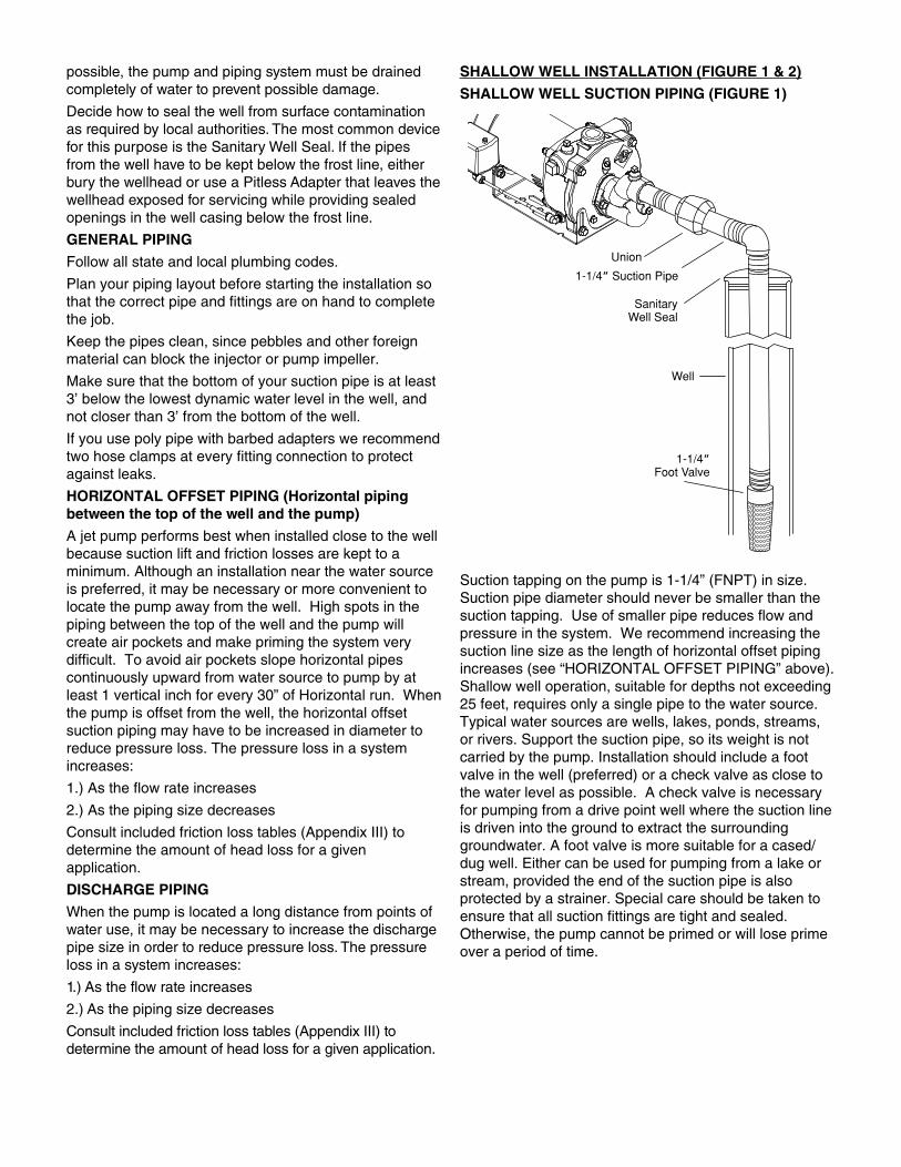
SHALLOW WELL INSTALLATION (FIGURE 1 & 2)
SHALLOW WELL SUCTION PIPING (FIGURE 1)
Suction tapping on the pump is 1-1/4” (FNPT) in size. Suction pipe diameter should never be smaller than the suction tapping. Use of smaller pipe reduces flow and pressure in the system. We recommend increasing the suction line size as the length of horizontal offset piping increases (see “HORIZONTAL OFFSET PIPING” above). Shallow well operation, suitable for depths not exceeding 25 feet, requires only a single pipe to the water source. Typical water sources are wells, lakes, ponds, streams, or rivers. Support the suction pipe, so its weight is not carried by the pump. Installation should include a foot valve in the well (preferred) or a check valve as close to the water level as possible. A check valve is necessary for pumping from a drive point well where the suction line is driven into the ground to extract the surrounding groundwater. A foot valve is more suitable for a cased/dug well. Either can be used for pumping from a lake or stream, provided the end of the suction pipe is also protected by a strainer. Special care should be taken to ensure that all suction fittings are tight and sealed. Otherwise, the pump cannot be primed or will lose prime over a period of time.
1-1/4” Suction Pipe
SanitaryWell Seal
Well
1-1/4”Foot Valve
Union
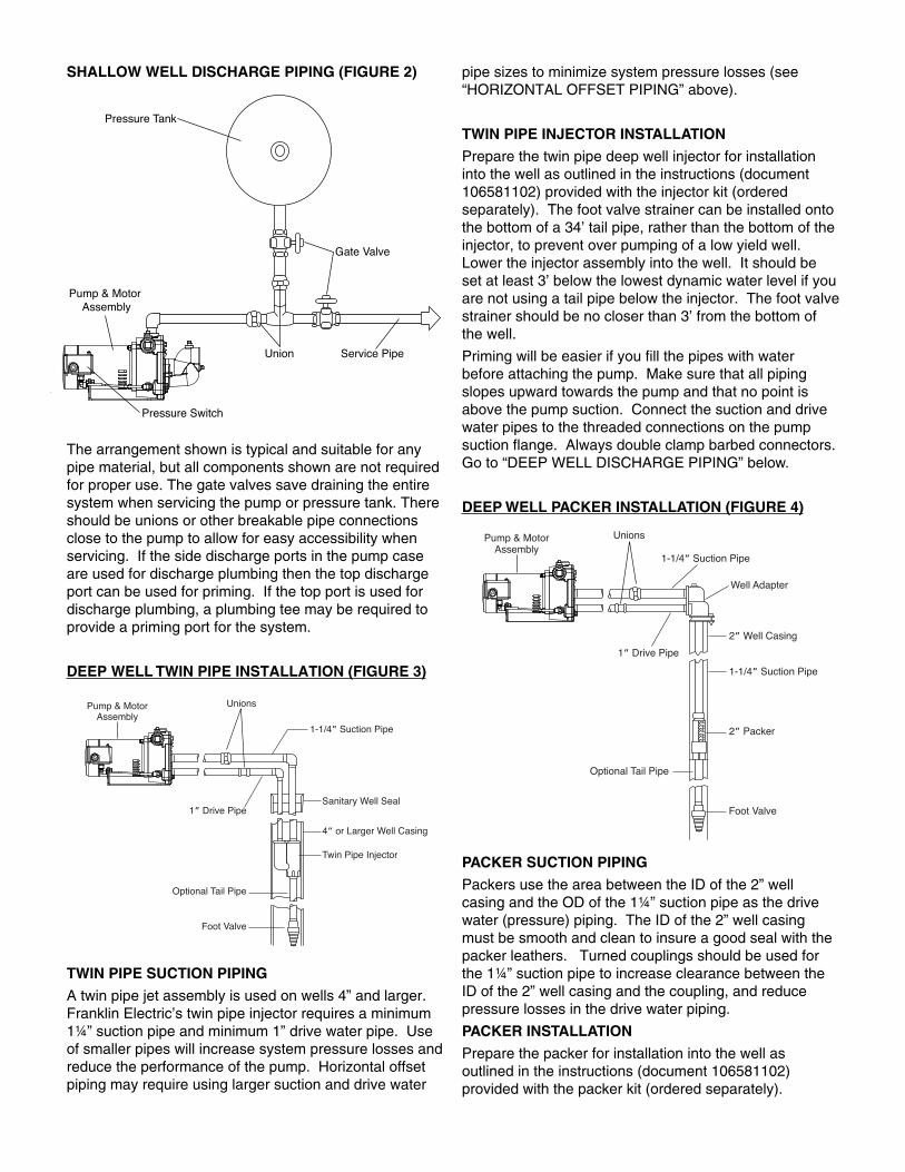
SHALLOW WELL DISCHARGE PIPING (FIGURE 2)
The arrangement shown is typical and suitable for any pipe material, but all components shown are not required for proper use. The gate valves save draining the entire system when servicing the pump or pressure tank. There should be unions or other breakable pipe connections close to the pump to allow for easy accessibility when servicing. If the side discharge ports in the pump case are used for discharge plumbing then the top discharge port can be used for priming. If the top port is used for discharge plumbing, a plumbing tee may be required to provide a priming port for the system.
DEEP WELL TWIN PIPE INSTALLATION (FIGURE 3)
TWIN PIPE SUCTION PIPING
A twin pipe jet assembly is used on wells 4” and larger. Franklin Electric’s twin pipe injector requires a minimum 1¼” suction pipe and minimum 1” drive water pipe. Use of smaller pipes will increase system pressure losses and reduce the performance of the pump. Horizontal offset piping may require using larger suction and drive water
pipe sizes to minimize system pressure losses (see “HORIZONTAL OFFSET PIPING” above).
TWIN PIPE INJECTOR INSTALLATION
Prepare the twin pipe deep well injector for installation into the well as outlined in the instructions (document 106581102) provided with the injector kit (ordered separately). The foot valve strainer can be installed onto the bottom of a 34’ tail pipe, rather than the bottom of the injector, to prevent over pumping of a low yield well. Lower the injector assembly into the well. It should be set at least 3’ below the lowest dynamic water level if you are not using a tail pipe below the injector. The foot valve strainer should be no closer than 3’ from the bottom of the well.
Priming will be easier if you fill the pipes with water before attaching the pump. Make sure that all piping slopes upward towards the pump and that no point is above the pump suction. Connect the suction and drive water pipes to the threaded connections on the pump suction flange. Always double clamp barbed connectors.Go to “DEEP WELL DISCHARGE PIPING” below.
DEEP WELL PACKER INSTALLATION (FIGURE 4)
PACKER SUCTION PIPING
Packers use the area between the ID of the 2” well casing and the OD of the 1¼” suction pipe as the drive water (pressure) piping. The ID of the 2” well casing must be smooth and clean to insure a good seal with the packer leathers. Turned couplings should be used for the 1¼” suction pipe to increase clearance between the ID of the 2” well casing and the coupling, and reduce pressure losses in the drive water piping.
PACKER INSTALLATION
Prepare the packer for installation into the well as outlined in the instructions (document 106581102) provided with the packer kit (ordered separately).
UnionsPump & MotorAssembly
1-1/4” Suction Pipe
Sanitary Well Seal
4” or Larger Well Casing
Twin Pipe Injector
1” Drive Pipe
Optional Tail Pipe
Foot Valve
UnionsPump & MotorAssembly
1-1/4” Suction Pipe
1” Drive Pipe
Well Adapter
2” Well Casing
1-1/4” Suction Pipe
2” Packer
Foot Valve
Optional Tail Pipe
Pressure Switch
Union Service Pipe
Gate Valve
Pressure Tank
Pump & Motor Assembly

The foot valve strainer can be installed onto the bottom of a 34’ long tail pipe, rather than the bottom of the packer, to prevent over pumping of a low yield well. Soak the packer assembly in warm water for 1 hour to make the leathers soft and pliable. Lower or push the packer assembly into the well on 1¼” suction piping. It should be set at least 3’ below the lowest dynamic water level if you are not using a tail pipe below the packer.The foot valve strainer should be no closer than 3’ from the bottom of the well.
WELL ADAPTER INSTALLATION
Packer systems require a well adapter (ordered separately) at the top of the well. The well adapter makes the transition from the vertical suction pipe and well casing, to the horizontal suction and drive water connections. The 1¼” suction pipe from the well must be terminated with a 1¼” male NPT connection. Attach the well adapter to this 1¼” male NPT fitting. Make sure the OD of the well casing is smooth and clean. With the gland bolts loosened, the rubber seal ring should slide over the 2” well casing. With the well adapter in place, tighten the 3 gland bolts uniformly to compress the seal ring to the well casing OD. The Convertible VersaJet pump can be attached directly to the well adapter using the two 3/8”-16 x 1” bolts with flat washers supplied with the well adapter kit, and the rubber gasket provided with the suction flange kit. The pump may be separated from the well adapter with horizontal offset suction and drive
water piping.
(see “HORIZONTAL OFFSET PIPING” above).
Priming will be easier if you fill the pipes with water before attaching the pump. Make sure that all piping slopes upward towards the pump and that no point is above the pump suction. Connect the suction and drive water pipes to the threaded connections on the pump suction flange. Always double clamp barbed connectors.
Go to “DEEP WELL DISCHARGE PIPING” below
DEEP WELL DISCHARGE PIPING (FIGURE 5)
All deep well jet pumps require back pressure to properly operate the jet assembly. To insure that you have the required back pressure or drive water pressure, you must provide a pressure control valve in the discharge line as close to the pump as possible. Failure to install and adjust a pressure control valve will result in loss of prime during peak usage situations. Franklin Electric recommends the use of a 1” control valve (Franklin Electric control valve P/N 91980359) installed directly in the pump discharge that has an alternate ¼” NPT pressure switch connection. This alternate pressure switch connection allows the switch to read the pressure on the outbound side of the valve, rather than inside the pump case. Install the control valve in the pump discharge. Remove the plastic tubing from the quick connect fittings supplied on the pump. Remove the quick connect fitting from the pump case and move it to the ¼” NPT connection on the control valve. Plug the ¼” NPT pump case hole with the plug provided in the control valve kit. Install the new plastic hose between the pressure switch and the control valve (cut it to the proper length if necessary). Make sure you push the plastic hose completely into the quick connect fittings to insure a good water seal. See “ADJUSTING THE CONTROL VALVE” below for adjustment procedures of this valve.
The arrangement shown in FIGURE 5 is typical and suitable for any pipe material, but all components shown are not required for proper use. The gate valves save draining the entire system when servicing the pump or pressure tank. There should be unions or other breakable pipe connections close to the pump to allow for easy accessibility when servicing. If the side discharge ports in the pump case are used for discharge plumbing then the top discharge port can be used for priming. If the top port is used for discharge plumbing, priming can be done through the top of the control valve installed in this port.
PRIMING THE PUMPSHALLOW WELL PUMPS
Priming the pump means filling the pump and suction piping with water. Priming is completed when you start the pump, and all the air is removed from the piping system, but before you energize the pump you must manually fill the pump and suction piping with water. If you used one of the side discharge connections on the pump, you can easily fill the pump and piping with water through the 1” top port. If you used the top port for discharge plumbing, you may need to provide a priming tee for filling with water. Please also remove the ¼” pipe plug on top of the shallow well injector for venting purposes while filling. Once this ¼” vent hole produces only water, it should be plugged, and continue filling the pump with water until full. All horizontal offset piping should slope up from the well to the pump to ensue that it is filled with water. Plug the filling hole and open slightly a faucet close to the pump. Do not open it too much, which will allow too much water to escape when you
Pressure Switch
Union Service Pipe
Gate Valve
Pressure Tank
Check Valve
Pump & MotorAssembly
Priming Port
Pressure Control Valve
Alternate Pressure SwitchTubing Connection
230V
11
5V
230V
115V
115V 230V
FIGURE 6
energize the pump, and you will have to re-prime the system. Once the pump is turned on it may take several minutes to remove all of the air from the system. On installations with long suction piping, you may have to add water several times to complete the priming process.
DEEP WELL PUMPS
Priming the pump means filling the pump, suction piping, and drive water piping with water. Priming is completed when you start the pump, and all the air is removed from the piping system, but before you energize the pump you must manually fill the pump and piping with water. Deep well installations require a complete prime before starting the pump. If you used one of the side discharge connections on the pump, you can easily fill the pump and piping with water through the 1” top port. If you installed the control valve in the top discharge port, you can prime the pump through the 1” priming hole in the top of the valve. You will need to provide a priming tee if you used the top discharge port but did not install the control valve there. Fill the pump with water until full. All horizontal offset piping should slope up from the well to the pump to ensue that it is filled with water. Plug the priming hole. Perform the “ADJUSTING THE CONTROL VALVE” procedure listed below. Once the pump is turned on it may take several minutes to remove all of the air from the system. On installations with long suction and drive water piping, you may have to add water several times to complete the priming process.
ELECTRICAL INSTALLATIONWARNING Hazardous voltage can
shock, burn or cause death.
C A U T I O N If you are not sure of proper electrical connections, consult a licensed electrician.
C A U T I O N Improper wiring can result in permanent damage to the motor. All electrical wiring should meet the local electrical code.
NOTICE:READ AND FOLLOW ALL INSTRUCTIONS!
Pump connection must comply with National Electric Code (NEC) or Canadian Electric Code (CEC), and all applicable local codes.
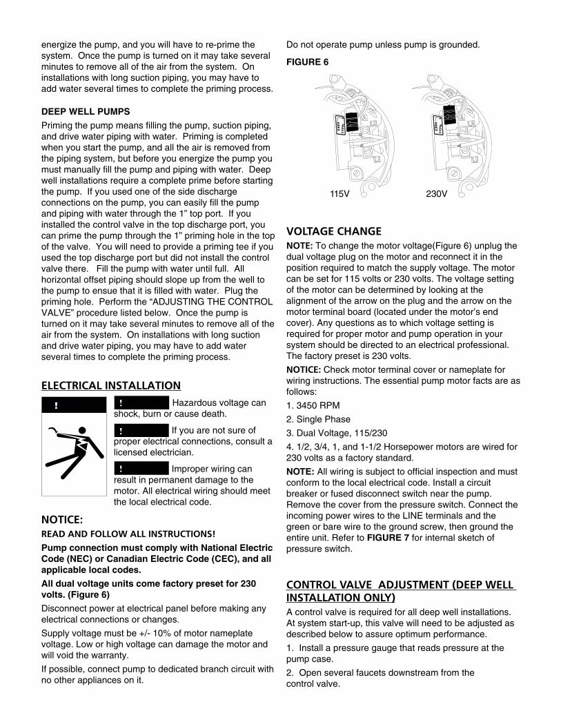
All dual voltage units come factory preset for 230 volts. (Figure 6)
Disconnect power at electrical panel before making any electrical connections or changes.
Supply voltage must be +/- 10% of motor nameplate voltage. Low or high voltage can damage the motor and will void the warranty.
If possible, connect pump to dedicated branch circuit with no other appliances on it.
Do not operate pump unless pump is grounded.
VOLTAGE CHANGENOTE: To change the motor voltage(Figure 6) unplug the dual voltage plug on the motor and reconnect it in the position required to match the supply voltage. The motor can be set for 115 volts or 230 volts. The voltage setting of the motor can be determined by looking at the alignment of the arrow on the plug and the arrow on the motor terminal board (located under the motor’s end cover). Any questions as to which voltage setting is required for proper motor and pump operation in your system should be directed to an electrical professional. The factory preset is 230 volts.
NOTICE: Check motor terminal cover or nameplate for wiring instructions. The essential pump motor facts are as follows:
1. 3450 RPM
2. Single Phase
3. Dual Voltage, 115/230
4. 1/2, 3/4, 1, and 1-1/2 Horsepower motors are wired for 230 volts as a factory standard.
NOTE: All wiring is subject to official inspection and must conform to the local electrical code. Install a circuit breaker or fused disconnect switch near the pump. Remove the cover from the pressure switch. Connect the incoming power wires to the LINE terminals and the green or bare wire to the ground screw, then ground the entire unit. Refer to FIGURE 7 for internal sketch of pressure switch.
CONTROL VALVE ADJUSTMENT (DEEP WELL INSTALLATION ONLY)A control valve is required for all deep well installations. At system start-up, this valve will need to be adjusted as described below to assure optimum performance.
1. Install a pressure gauge that reads pressure at the pump case.
2. Open several faucets downstream from the control valve.
WARNING

3. Loosen control valve locking screw.
4. Rotate the valve to the closed position.
5. Prime the pump (completely fill pump and piping with water)
6. Start pump
7. Open valve slowly until a rapid drop in pressure and flow is noticed, or grinding/ticking noise in the pump is heard. This point is sometimes associated with fluttering of the pressure gauge needle. Begin rotating the valve in the opposite direction (towards closing) until flow and pressure are stabilized and/or the noise is gone.
8. Tighten the locking screw.
PRESSURE SWITCH ADJUSTMENTThe pressure switch is set to start the pump at 30 psi and to stop at 50 psi. THE PRESSURE SWITCH SHOULD NOT REQUIRE ADJUSTMENT FOR A TYPICAL PUMP INSTALLATION. Adjust the switch only if necessary, using the following procedure:
1.) Turn DIFFERENTIAL nut (See FIGURE 7 and table below) clockwise to increase the pressure difference between CUT-IN (pump on) and CUT-OUT (pump off) by raising the CUT-OUT pressure.
2.) Turn RANGE nut (See FIGURE 7 and table below) clockwise to simultaneously increase both the CUT-IN and CUT-OUT pressure equally.
NOTE: An optional pressure gage is required when adjusting the pressure switch to determine when the desired pressure settings are achieved. For shallow well installations, a pressure port has been provided in the top of the pump near the discharge for this purpose. For deep well installations, the pressure gauge needs to be located between the control valve and the pressure tank.
DO NOT switch on the power before the pump is primed by filling the pump case completely full of water, as damage may occur to the seal and other internal components if run dry.
PRESSURE SWITCH ADJUSTMENT EXAMPLE:
ASSUMES PRESSURE SWITCH IS INITIALLY SET WITH A CUT-IN PRESSURE OF 30 PSI AND CUT-OUT PRESSURE OF 50 PSI.
StartingCUT-IN / CUT-OUT
(psi)
Nut Adjustment
FinalCUT-IN / CUT-OUT
(psi)
30/50Clockwise turn of Differential Nut
30/60
30/50Clockwise turn of
Range Nut40/60
NOTICE: FAILURE TO ADJUST PRESSURE SWITCH CUT-IN AND CUT-OUT SETTINGS PROPERLY MAY CAUSE THE PUMP TO RUN CONTINUOUSLY OR CYCLE RAPIDLY. CONTINUOUS OPERATION OR RAPID CYCLING WILL DAMAGE PUMP AND MAY CAUSE PREMATURE FAILURE OF OTHER SYSTEM COMPONENTS.
INSTALLATION RECORDSTo keep an accurate record of your installation, be sure to fill out the data below:
Date of Installation: _____________________________
Pump Model No: _______________________________
Depth of Well (ft.): ______________________________
Depth of Water (ft.): _____________________________
Inside diameter of well: __________________________
Suction pipe size: ______________________________
Drive water pipe size (Deep well only): ______________
Pressure switch setting
C.I.: _____________ C.O.: _____________
Suction pipe length (ft.): _________________________
Discharge pipe length (ft.): _______________________
Motor manufacturer: ____________________________
Motor model No: _______________________________
HP: _________________________________________
Volts: ________________________________________
Wire gauge size: _______________________________
GROUND
LIN
E
LIN
E
LOA
D
LOA
D
Differential Nut
Range Nut
To circuit breakeror fused
disconnect switch
FIGURE 7 - PRESSURE SWITCH ELECTRICAL CONNECTIONS, FACTORY PRE-SET TO 230 VOLTS

MAINTENANCELUBRICATION
The pump requires only water for lubrication and must never be run dry.
C A U T I O N Running the pump dry may cause damage to the pump and system components.
WARNING Before disconnecting pump, be sure fuse box leads are disconnected or power is turned off. After reassembling the pump, refer to priming instructions before running.
DRAININGIf your pump must be drained for service or to prevent damage from freezing, remove the drain plug from the pump case.NOTICE: While this will drain the pump, it will not necessarily drain all other parts of the piping system. If there are any concerns with the proper procedure or necessity of draining the suction plumbing, contact your contractor.
All piping and water tanks exposed to freezing weather should be drained. If there are any concerns with the proper procedure to drain the systems pressure tank, contact the tank manufacturer for assistance.
PUMP DISASSEMBLYWARNING Before disconnecting pump, be sure fuse
box leads are disconnected or power is turned off at the breaker box. After reassembling the pump, refer to priming instructions before running.
DISASSEMBLY
If you experience problems with your pump, determine the trouble from the service check list (see TROUBLESHOOTING below). If the shallow well jet nozzle needs cleaning, it can be accessed through the ¼” inline plug on the shallow well injector housing bolted to front of the pump. If you need to service the impeller, motor or seal, use the following procedure, going as far as needed to correct the problem:
1.Disconnect the power to the unit.
2.Disconnect the pump from the piping system at the piping unions. If there are no piping unions in your plumbing system the discharge line will have to be cut.
3.Remove the suction flange and base from the front of the pump by unscrewing the four 3/8”-16 bolts.
4.Remove the rubber grommet from the eye of the diffuser.
5.Unscrew the three socket head screws that hold the diffuser inside the pump case, and remove the diffuser.
6.Remove the stainless steel floating eye seal from the eye of the impeller.
7.Remove the cover from the opposite end of the motor and hold the shaft with a 7/16” open end wrench. The motor shaft is flatted behind the centrifugal switch, close to motor end bell. The open end wrench can be inserted down onto the shaft from behind the motor overload.
8.Unscrew the impeller from the motor shaft by grasping the OD of the impeller with a gloved hand and rotating counterclockwise.
9.Remove the rotating portion of the shaft seal from the motor shaft.
10.Remove the motor from the bracket by unscrewing the four 3/8”-16 bolts.
11.Tap the stationary portion of the seal out of the pump bracket with a flat bladed screwdriver.
12.Reassemble in reverse order. Clean the seals and the sealing surfaces in the pump case. Lightly lubricate the rubber part of the seals with silicone grease to aid in assembly. DO NOT lubricate the carbon or ceramic faces on the shaft seal.

1.2.
3.
How to navigate this chart:
Identify symptom @ top leftMove to right and find highlighted cells that identify possible causes belowMove down below listed causes and find highlighted cells that identify remedies to the bottom left
CA
USE
SB
reak
er tr
ippe
d, o
pen
switc
h or
loos
e w
ire c
onnc
tions
Impr
oper
ele
ctric
al c
onne
ctio
ns
Def
ectiv
e m
otor
Impr
oper
vol
tage
con
nect
ion
Poo
r mot
or v
entil
atio
n
Impr
oper
runn
ing
volta
ge a
t mot
or te
rmin
als
Pum
p is
not
prim
ed
Plu
mbi
ng s
uctio
n le
ak
Plu
mbi
ng d
isch
arge
leak
Dis
char
ge o
r suc
tion
pipi
ng p
lugg
ed, v
alve
clo
sed
Wat
er le
vel i
s m
ore
than
25
feet
bel
ow in
ject
or (T
his
appl
ies
to a
de
ep w
ell a
pplic
atio
n w
ith a
25
foot
tail
pipe
)
Wat
er le
vel b
elow
inje
ctor
is d
eepe
r tha
n an
ticip
ated
Inje
ctor
noz
zle
plug
ged
Impe
ller p
orts
plu
gged
Leak
ing
chec
k or
foot
val
ve
Wat
er lo
gged
pre
ssur
e ta
nk
Hig
h fri
ctio
n lo
ss b
etw
een
pum
p an
d pr
essu
re ta
nk, p
artia
lly
clos
ed d
isch
arge
val
ve
Pre
ssur
e sw
itch
cut-o
ut s
ettin
g to
o hi
gh
Suc
tion
line
rest
rictio
n, s
uctio
n pi
ping
too
smal
l, pa
rtial
ly c
lose
d su
ctio
n va
lve
Dee
p w
ell c
ontro
l val
ve o
pen
too
muc
h
Wat
er le
vel d
rops
bel
ow s
uctio
n in
let
Recharge pressure tank to 2 PSI below pressure switch cut-in settingIncrease size or clean out discharge pipe between pump and pressure tank
Lower pressure switch cut-out pressure as described in"PRESSURE SWICH ADJUSTMENT" in this manualIncrease size or clean out suction piping to pump
Clear nozzle or impeller of clogging debris. See "PUMP DISASSEMBLY" in manualConvert a shallow well application into a deep well arrangement. Lower the injector setting in a deep well applicationConsult pump performance table and select alternate injector assembly or pump that will produce required performance at well conditionsReplace faulty check or foot valve
Make sure motor vents are not blocked and/or improve vent clearance around motor
Follow "PRIMING THE PUMP" proceedure as outlinedin this manual
Check all plumbing joints and connections for leaksMake sure all valves are fully open and all piping is free from obstructions
Have qualified elctrician check for low or high running voltage at motor terminal. Electrician will need to correct if necessary.
Excessive air in water
Check wiring, switches and breakersCall your dealerMake sure motor voltage setting and incoming voltagematch
Excessive cycling of pumpLoss of pressure with no water usagePump runs continuouslyGravelly noise from pumpSY
MPT
OM
SCVJ TROUBLESHOOTING GUIDE
REM
EDIE
S
Perform "CONTROL VALVE ADJUSTMENT" as described in this manualFor shallow well applications lower suction inlet in well. If this length becomes greater than 25 feet, you will need to convert to a deep well system. For deep well applications you will need to lower the injector in the well.
Motor not runningMotor overheatsPump does not deliver water or pressureLow pressure from pumpLow flow from pump

PARTS FOR CONVERTIBLE VERSAJET PUMP
1A
6D
5C
5C
9E
2B 9E
5C,G
13G
11G12G
5C,G
5C,G
189E
4F
10F14H
15H
16H
5C
17F
9E
5C
5C
Number DescriptionKit Group Identifier
Repair Part Order Codes by Model NumberCVJ05CI CVJ05CI-P CVJ07CI CVJ07CI-P CVJ10CI CVJ10CI-P CVJ15CI
1 Motor A 305374901 305374903 305374902 305374906 305374904 305374907 3053749052 Studs
B 3054659013 Bracket4 O-Ring F 3054659025 Fasteners C 3054659036 Pressure Switch
D 3054659047 Pressure Hose Fitting8 Pressure Hose Tubing9 Plugs E 30546590510 Mechanical Seal F 30546590211 Base Protector
G 30546590612 Base Extension13 Base14 Impeller
H 305465907 305465908 305465909 30546591015 Wear Ring16 Diffuser17 Grommet F 305465902
N/A Overhaul Kit* I 305465911 305465912 305465913 30546591418 Pump Face Plate See Face Plate Ordering Table
*Overhaul Kit includes kits C, E, F, H

LIMITED WARRANTY*THIS WARRANTY SETS FORTH THE COMPANY’S SOLE OBLIGATION AND PURCHASER’S EXCLUSIVE REMEDY FOR DEFECTIVE PRODUCT.
Franklin Electric Company, Inc. and its subsidiaries (hereafter “the Company”) warrants that the products accompanied by this warranty are free from defects in material or workmanship of the Company.
The Company has the right to inspect any product returned under warranty to confirm that the product contains a defect in material or workmanship. The Company shall have the sole right to choose whether to repair or replace defective equipment, parts, or components.
The buyer should return the product to the place of purchase for warranty consideration. Subject to the terms and conditions listed below, the Company will repair or replace to the buyer any portion of this product which proves defective due to materials or workmanship of the Company.
The company will consider products for warranty for 12 months (1-year) from the date of installation or for 24 month (2-years) from the date of manufacture, whichever occurs first. This limited warranty extends only to the products purchased directly from Franklin Electric and is not assignable or transferable to any subsequent purchaser or user.
The Company shall IN NO EVENT be responsible or liable for the cost of field labor or other charges incurred by any customer in removing and/or affixing any product, part or component thereof.
The Company reserves the right to change or improve its products or any portions thereof without being obligated to provide such change or improvement to previously sold products.
THIS WARRANTY DOES NOT APPLY TO products damaged by acts of God, including lightning, normal wear and tear, normal maintenance services and the parts used in connection with such service, or any other conditions beyond the control of the Company.
THIS WARRANTY WILL IMMEDIATELY VOID if any of the following conditions are found:
1. Product is used for purposes other than those for which it was designed and manufactured; 2. Product was not installed in accordance with applicable codes, ordinances and good trade practices; 3. Product was not installed by a Franklin Certified Contractor or Franklin Key Dealer; or 4. Product was damaged as a result of negligence, abuse, accident, misapplication, tampering, alteration, improper installation, operation, maintenance or storage, nor to an excess of recommended maximums as set forth in the product instructions.
NEITHER SELLER NOR THE COMPANY SHALL BE LIABLE FOR ANY INJURY, LOSS OR DAMAGE, DIRECT, INCIDENTAL OR CONSEQUENTIAL (INCLUDING, BUT NOT LIMITED TO, INCIDENTAL OR CONSEQUENTIAL DAMAGES FOR LOST PROFITS, LOST SALES, INJURY TO PERSON OR PROPERTY, OR ANY OTHER INCIDENTAL OR CONSEQUENTIAL LOSS), ARISING OUT OF THE USE OR THE INABILITY TO USE THE PRODUCT, AND THE BUYER AGREES THAT NO OTHER REMEDY SHALL BE AVAILABLE TO IT.
THE WARRANTY AND REMEDY DESCRIBED IN THIS LIMITED WARRANTY IS AN EXCLUSIVE WARRANTY AND REMEDY AND IS IN LIEU OF ANY OTHER WARRANTY OR REMEDY, EXPRESS OR IMPLIED, WHICH OTHER WARRANTIES AND REMEDIES ARE HEREBY EXPRESSLY EXCLUDED, INCLUDING BUT NOT LIMITED TO ANY IMPLIED WARRANTY OF MERCHANTABILITY OR FITNESS FOR A PARTICULAR PURPOSE, TO THE EXTENT EITHER APPLIES TO A PRODUCT SHALL BE LIMITED IN DURATION TO THE PERIODS OF THE EXPRESSED WARRANTIES GIVEN ABOVE.
DISCLAIMER: Any oral statements about the product made by the seller, the Company, the representatives or any other parties, do not constitute warranties, shall not be relied upon by the buyer, and are not part of the contract for sale. Seller’s and the Company’s only obligation, and buyer’s only remedy, shall be the replacement and/or repair by the Company of the product as described above. Before using, the user shall determine the suitability of the product for his intended use, and user assumes all risk and liability whatsoever in connection therewith.
Some states and countries do not allow the exclusion or limitations on how long an implied warranty lasts or the exclusion or limitation of incidental or consequential damages, so the above exclusion or limitations may not apply to you. This warranty gives you specific legal rights, and you may also have other rights which vary from state to state and country to country.
*Contact Franklin Electric Co., Inc. Export Division for International Warranty.

106580101 Rev. 2 07.13
9255 Coverdale Road, Fort Wayne, IN 46809Tel: 260.824.2900 Fax: 260.824.2909 www.franklinwater.com