![[XLS]Brocade · Web view600W AC Power Supply for FES-POE models, FESX448/648 models, FESX424-POE models and FastIron GS models (POE and non-POE) E1MG-BXD 1000Base-BXD SFP optic SMF,](https://static.fdocuments.in/doc/165x107/5afbf6ef7f8b9a8b4d8b8567/xlsbrocade-view600w-ac-power-supply-for-fes-poe-models-fesx448648-models-fesx424-poe.jpg)
Convert fiber to copper, plus provide PoE 15.5W of … · Laser Klasse 1, Appareil A’Laser de ......
24
LGC5200A LGC5211A LGC5200-WALL LGC5201A LGC5212A LGC5202A LGC5200-PS LGC5210A LGC5210-PS PoE, PoE+ 10/100/1000 Media Converters Convert fiber to copper, plus provide PoE 15.5W of power or PoE+ 25.5W of power to PoE/PoE+ Devices (PD).
Transcript of Convert fiber to copper, plus provide PoE 15.5W of … · Laser Klasse 1, Appareil A’Laser de ......

LGC5200A LGC5211A LGC5200-WALL LGC5201A LGC5212A LGC5202A LGC5200-PS LGC5210A LGC5210-PS
PoE, PoE+ 10/100/1000 Media Converters
Convert fiber to copper, plus provide PoE 15.5W of power or PoE+ 25.5W of power to PoE/PoE+ Devices (PD).
Page 2 724-746-5500 | blackbox.com LGC5200A
Trademarks Black Box and the Double Diamond logo are registered trademarks of BB Technologies, Inc.
Any other trademarks mentioned in this manual are acknowledged to be the property of the trademark owners.
FCC and IC RFI Statements
LGC5200A 724-746-5500 | blackbox.com Page 3
FCC and Industry Canada RF Interference Statements This equipment generates, uses, and can radiate radio-frequency energy, and if not installed and used properly, that is, in strict accordance with the manufacturer’s instructions, may cause interference to radio communication. It has been tested and found to comply with the limits for a Class A computing device in accordance with the specifications in Subpart B of Part 15 of FCC rules, which are designed to provide reasonable protection against such interference when the equipment is operated in a commercial environment. Operation of this equipment in a residential area is likely to cause interference, in which case the user at his own expense will be required to take whatever measures may be necessary to correct the interference. Changes or modifications not expressly approved by the party responsible for compliance could void the user’s authority to operate the equipment. This digital apparatus does not exceed the Class A limits for radio noise emission from digital apparatus set out in the Radio Interference Regulation of Industry Canada. Le présent appareil numérique n’émet pas de bruits radioélectriques dépassant les limites applicables aux appareils numériques de la classe A prescrites dans le Règlement sur le brouillage radioélectrique publié par le Industrie Canada.

Certifications
Page 4 724-746-5500 | blackbox.com LGC5200A
Certifications
European Directive 2002/96/EC (WEEE) requires that any equipment that bears this symbol on product or packaging must not be disposed of with unsorted municipal waste. This symbol indicates that the equipment should be disposed of separately from regular household waste. It is the consumer’s responsibility to dispose of this and all equipment so marked through designated collection facilities appointed by government or local authorities. Following these steps through proper disposal and recycling will help prevent potential negative consequences to the environment and human health. For more detailed information about proper disposal, please contact local authorities, waste disposal services, or the point of purchase for this equipment.
Class 1 Laser product, Luokan 1 Laserlaite, Laser Klasse 1, Appareil A’Laser de Classe

Table of Contents
LGC5200A 724-746-5500 | blackbox.com Page 5
Table of Contents Part Numbers ...................................................................................................... 6 1. Specifications ......................................................................................... 7 2. Overview: About the PoE, PoE+ 10/100/1000 Media Converters ........ 9 3. Configuration ........................................................................................ 10 3.1 DIP Switch Configurations—LGC5200 Series, SFP ............................ 10 3.1.1 PoE Reset DSW for LGC5200 Series, SFP ......................................... 10 3.2 Link Fault Pass-Through (LFPT) DSW for PoE Giga-MiniMc .............. 10 3.3 DIP Switch Configurations—LGC5200 Series, 1x9 ............................. 11 3.3.1 PoE Reset DSW for LGC5200 Series, 1x9 .......................................... 11 3.4 DIP Switch Configurations—LGC5210 Series, SFP ............................ 12 3.4.1 PoE Reset DSW for LGC5210 Series, SFP ......................................... 12 3.5 LFPT DSW for PoE+ Giga-MiniMc ....................................................... 12 3.6 DIP Switch Configurations—LGC5210 Series, 1x9 ............................. 13 3.6.1 PoE Reset DSW LGC5210 Series, 1x9 ............................................... 13 4. Install the PoE, PoE+ 10/100/1000 Media Converters ........................ 14 4.1 Powering Options ................................................................................. 14 4.1.1 DC Terminal Block Wiring Instructions ................................................. 15 4.1.2 DC Power Supply Precautions ............................................................. 15 4.2 Mounting Options ................................................................................. 17 5. Operation .............................................................................................. 18 5.1 LED Operation—SFP ........................................................................... 18 5.1.1 SFP LED Functions .............................................................................. 18 5.1.2 RJ-45 LED Functions ........................................................................... 18 5.2 LED Operation—1x9 ............................................................................ 19 5.2.1 1x9 LED Functions ............................................................................... 19 5.2.2 RJ-45 LED Functions ........................................................................... 19 6. Troubleshooting .................................................................................... 20 7. Contacting Black Box ........................................................................... 21 8. Fiber Optic Cleaning Guidelines .......................................................... 22 9. Electrostatic Discharge Precautions .................................................... 23

Part Numbers
Page 6 724-746-5500 | blackbox.com LGC5200A
Part Numbers
Part Number Description
LGC5200A PoE 10/100/1000 Media Converter, SFP
LGC5201A PoE 10/100/1000 Media Converter, MM850NM, AC 2220/550 M
LGC5202A PoE 10/100/1000 Media Converter, SM 1310NM, SC 15 KM
LGC5210A PoE+ 10/100/1000 Media Converter, SFP
LGC5211A PoE+ 10/100/1000 Media Converter, SM 850 NM SC 220/550 M
LGC5212A PoE+ 10/100/1000 Media Converter, SM 1310NM, SC 15KM
LGC5200-PS PoE Power Adapter for LGC5200 series
LGC5210-PS PoE+ Power Adapter for LGC5210 series
LGC5200-WALL LGC5200 Series Wallmount

Chapter 1: Specifications
LGC5200A 724-746-5500 | blackbox.com Page 7
1. Specifications
DC Input LGC5200 Series:
45 VDC to 57 VDC on DC terminal block
48 VDC on DC jack
LGC5210 Series:
51 to 57 VDC on DC terminal block
51 to 57 VDC on DC jack
AC Desktop Adapter
LGC5200 Series: Input: 100 to 240 ±10% VAC, 50/60Hz, 0.7A * Output: 48 VDC, 0.62A
LGC5210 Series:
Input: 100 to 240 ±10% VAC, 50/60Hz, 2A*
Output: 52 VDC, 2.31A
Power Consumption
LGC5200 Series:
21W max (PSE + PD)
5W max (PSE)
LGC5210 Series:
65W max (PSE + PD)
5W max (PSE)
Operating Temperature
+32°F to +158°F (0°C to +70°C) DC terminal block
+32°F to +122°F (0°C to +50°C) with AC desktop adapter
Storage Temperature
-40°F to +185°F (-40°C to +85°C)
Humidity 5% to 95% (non-condensing); 0 to 10,000 ft. altitude
Ethernet Connections
10/100/1000 BaseT Auto Negotiation AutoCross Flow Control 10240 MTU Full Line-Rate Forwarding
Chapter 1: Specifications
Page 8 724-746-5500 | blackbox.com LGC5200A
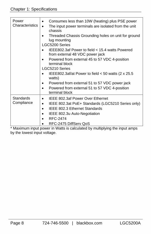
Power Characteristics
Consumes less than 10W (heating) plus PSE power The input power terminals are isolated from the unit
chassis Threaded Chassis Grounding holes on unit for ground
lug mounting LGC5200 Series IEEE802.3af Power to field < 15.4 watts Powered
from external 48 VDC power jack Powered from external 45 to 57 VDC 4-position
terminal block LGC5210 Series IEEE802.3af/at Power to field < 50 watts (2 x 25.5
watts) Powered from external 51 to 57 VDC power jack Powered from external 51 to 57 VDC 4-position
terminal block
Standards Compliance
IEEE 802.3af Power Over Ethernet IEEE 802.3at PoE+ Standards (LGC5210 Series only) IEEE 802.3 Ethernet Standards IEEE 802.3u Auto-Negotiation RFC-2474 RFC-2475 DiffServ QoS
* Maximum input power in Watts is calculated by multiplying the input amps by the lowest input voltage.

Chapter 2: Overview
LGC5200A 724-746-5500 | blackbox.com Page 9
2. Overview: About the PoE, PoE+ 10/100/1000 Media Converters
The PoE, PoE+ 10/100/1000 Media Converters are solutions for private network applications that require power over Ethernet for locations inside buildings where PoE is required to power an Ethernet device. The LGC5200 Series offer one SFP or fixed fiber transceiver, 1x9, uplink for the network connection, one PSE 10/100/1000Base-T copper port that provides Power-over-Ethernet (IEEE802.3af), and one 10/100/1000Mbps copper port. The LGC5210 Series offer one SFP or fixed fiber transceiver, 1x9, uplink for the network connection, and two PSE 10/100/1000Base-T copper ports that provides Power-over-Ethernet (IEEE802.3af).
As a fiber-fed demarcation unit, PoE, PoE+ 10/100/1000 Media Converters provide both power and data to a remote device over a standard CAT5 copper line, eliminating the need for a power connection to the remote device. The LGC5200 series provisions up to 15.4 watts on one copper port, and can be powered by an external AC adapter or DC terminal block. The LGC5210 Series provides up to 25.5W per copper port.
The SFP uplink can support fiber or copper SFPs. The fiber SFP, available in SC or LC connectors, supports 100FDX or 1000FDX; a copper SFP supports the SGMII interface (10/100/1000Mbps). The SFP must be MSA-compliant.
The copper ports auto negotiate to the connected device’s speed and duplex mode: 10 Mbps, 100 Mbps or 1000 Mbps, and HDX or FDX (including Flow Control). The PoE, PoE+ 10/100/1000 Media Converters support jumbo frames up to 10240.
NOTE
Unless noted otherwise, any reference is applicable for both the 1x9 and SFP versions of the PoE, PoE+ 10/100/1000 Media Converters in this manual.

Chapter 3: Configuration
Page 10 724-746-5500 | blackbox.com LGC5200A
3. Configuration
3.1 DIP Switch Configurations—LGC5200 Series, SFP
DIP Switch
Name Description Default Setting
1 PoE Reset ON forces Port 2, PSE/PoE, to OFF on LOS of fiber input
OFF
2 LFPT Port 1 ON enables LFPT for Port 1 and the FX Port OFF
3 LFPT Port 2 ON enables LFPT for Port 2 and the FX Port OFF
4 Factory Set Do not change OFF
5 Factory Set Do not change OFF
6 Factory Set Do not change OFF 3.1.1 PoE Reset DSW for LGC5200 Series, SFP When set to ON, it will force the PSE output power on the copper port OFF when the LINK state is lost on the SFP line (copper or fiber SFP). By default, the DSW is set to OFF. 3.2 Link Fault Pass-Through (LFPT) DSW for PoE Giga-MiniMc The DIP Switches for LFPT is to allow a Loss of Signal (LOS) fault to be passed through the unit. When enabled, if link is lost on the FX port, the transmit on the TX port is disabled. If link is lost on a TX port, the transmit on the FX Port is disabled.

Chapter 3: Configuration
LGC5200A 724-746-5500 | blackbox.com Page 11
3.3 DIP Switch Configurations—LGC5200 Series, 1x9
DIP Switch
Name Description Default Setting
1 PoE Reset ON forces Port 2, PSE/PoE, to OFF on LOS of fiber input
OFF
2 LFPT Port 1 ON enables LFPT for Port 1 and the FX Port OFF
3 LFPT Port 2 ON enables LFPT for Port 2 and the FX Port OFF
4 Factory Set Do not change OFF
5 Factory Set Do not change OFF
6 Factory Set Do not change OFF 3.3.1 PoE Reset DSW for LGC5200 Series, 1x9 When set to ON, it will force the PSE output power on the copper port OFF when the LINK state is lost on the fiber segment. By default, the DSW is set to OFF.
NOTEWith the fault switches – PoE Reset, LFPT Port1 and LFPT Port 2, only one fault condition is recognized at a time. The first fault condition is in charge. So if TX Port1 has no link and then the FX Port loses link, the loses of TX Port 1 link causes the FX Port to disable transmit.
Chapter 3: Configuration
Page 12 724-746-5500 | blackbox.com LGC5200A
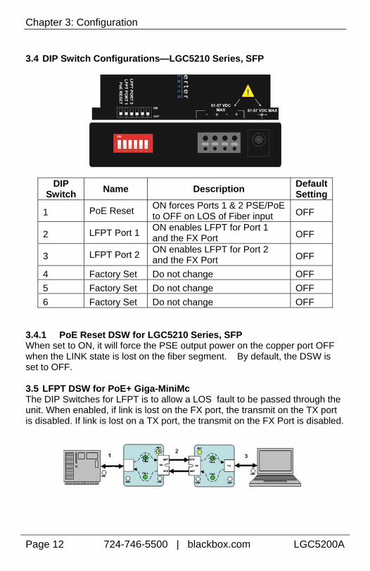
3.4 DIP Switch Configurations—LGC5210 Series, SFP
DIP Switch
Name Description Default Setting
1 PoE Reset ON forces Ports 1 & 2 PSE/PoE to OFF on LOS of Fiber input OFF
2 LFPT Port 1 ON enables LFPT for Port 1 and the FX Port OFF
3 LFPT Port 2 ON enables LFPT for Port 2 and the FX Port OFF
4 Factory Set Do not change OFF
5 Factory Set Do not change OFF
6 Factory Set Do not change OFF 3.4.1 PoE Reset DSW for LGC5210 Series, SFP When set to ON, it will force the PSE output power on the copper port OFF when the LINK state is lost on the fiber segment. By default, the DSW is set to OFF. 3.5 LFPT DSW for PoE+ Giga-MiniMc The DIP Switches for LFPT is to allow a LOS fault to be passed through the unit. When enabled, if link is lost on the FX port, the transmit on the TX port is disabled. If link is lost on a TX port, the transmit on the FX Port is disabled.

Chapter 3: Configuration
LGC5200A 724-746-5500 | blackbox.com Page 13
3.6 DIP Switch Configurations—LGC5210 Series, 1x9
DIP Switch
Name Description Default Setting
1 PoE Reset ON forces Ports 1 & 2 PSE/PoE to OFF on LOS of Fiber input OFF
2 LFPT Port 1 ON enables LFPT for Port 1 and the FX Port OFF
3 LFPT Port 2 ON enables LFPT for Port 2 and the FX Port OFF
4 Factory Set Do not change OFF
5 Factory Set Do not change OFF
6 Factory Set Do not change OFF 3.6.1 PoE Reset DSW LGC5210 Series, 1x9 When set to ON, it will force the PSE output power on the copper port OFF when the LINK state is lost on the fiber segment. By default, the DSW is set to OFF.
NOTE With the fault switches – PoE Reset, LFPT Port1 and LFPT Port 2, only one fault condition is recognized at a time. The first fault condition is in charge. So if TX Port1 has no link and then the FX Port loses link, the loss of TX Port 1 link causes the FX Port to disable transmit.

Chapter 4: Install the PoE, PoE+ 10/100/1000 Media Converters
Page 14 724-746-5500 | blackbox.com LGC5200A
4. Install the PoE, PoE+ 10/100/1000 Media Converters
CAUTION
The PoE, PoE+ 10/100/1000 Media Converters are for inside-a-building installation only. These devices cannot be installed outside-a-building environment as they cannot meet the PoE requirements, per the PoE standard. If installing the device outside, serious damage can occur.
PoE, PoE+ 10/100/1000 Media Converters install virtually anywhere: as a standalone, table-top device, on a DIN rail, or using a wallmount bracket. As a standalone device, the end user can install PoE, PoE+ 10/100/1000 Media Converters in locations with extremely limited space.
INSTALLATION TIP
Several models of the PoE, PoE+ 10/100/1000 Media Converters support single-strand fiber for operation. Since single-strand fiber products use optics that transmit and receive on two different wavelengths, single-strand fiber products must be deployed in pairs. For example, connect a PoE, PoE+ 10/100/1000 Media Converters , TX/SSLX-SM1310-SC (which has 1310 xmt and 1550 rcv) to a product which has 1550 xmt and 1310 rcv, e.g. PoE, PoE+ 10/100/1000 Media Converters , TX/SSLX-SM1550-SC. The two connected products must also have the same speed and distance capabilities (i.e. both are single-mode [20km] or both are single/PLUS [40km]).
4.1 Powering Options
As standalone units, the PoE, PoE+ 10/100/1000 Media Converters use a universal external desktop switching power adapter. The LGC5200 Series also include a DC terminal block to support a voltage range of 45 to 57 VDC while the LGC5210 Series includes a DC terminal block to support a voltage range of 51 to 57 VDC.
PoE, PoE+ 10/100/1000 Media Converters support two powering options.
Desktop AC power adapter with country specific power cord
The 4-terminal DC power block
Chapter 4: Install the PoE, PoE+ 10/100/1000 Media Converters
LGC5200A 724-746-5500 | blackbox.com Page 15
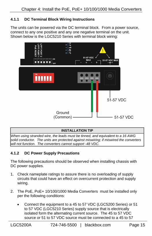
4.1.1 DC Terminal Block Wiring Instructions
The units can be powered via the DC terminal block. From a power source, connect to any one positive and any one negative terminal on the unit. Shown below is the LGC5210 Series with terminal block wiring:
INSTALLATION TIP
When using stranded wire, the leads must be tinned, and equivalent to a 16 AWG solid conductor. The units are protected against miswiring; if miswired the converters will not function. The converters cannot support -48 VDC.
4.1.2 DC Power Supply Precautions
The following precautions should be observed when installing chassis with DC power supplies.
1. Check nameplate ratings to assure there is no overloading of supply circuits that could have an effect on overcurrent protection and supply wiring.
2. The PoE, PoE+ 10/100/1000 Media Converters must be installed only per the following conditions:
Connect the equipment to a 45 to 57 VDC (LGC5200 Series) or 51 to 57 VDC (LGC5210 Series) supply source that is electrically isolated form the alternating current source. The 45 to 57 VDC source or 51 to 57 VDC source must be connected to a 45 to 57

Chapter 4: Install the PoE, PoE+ 10/100/1000 Media Converters
Page 16 724-746-5500 | blackbox.com LGC5200A
VDC SELV source or 51 to 57 VDC SELV source for the LGC5200 Series or LGC5210 Series, respectively.
The maximum terminal voltage is 57 VDC.
Input wiring to terminal block must be routed and secured in such a manner that it is protected from damage and stress. Do not route wiring past sharp edges or moving parts.
A readily accessible disconnect device, with a 3mm minimum contact gap, shall be incorporated in the fixed wiring.
3. Grounding: reliable grounding of this equipment must be maintained. Particular attention should be given to supply connections when connecting to power strips, rather than direct connections to the branch circuit. The Negative Terminal is common to the grounded case.
4. -48 VDC cannot be supported.

Chapter 4: Install the PoE, PoE+ 10/100/1000 Media Converters
LGC5200A 724-746-5500 | blackbox.com Page 17
4.2 Mounting Options
The PoE, PoE+ 10/100/1000 Media Converters can be mounted with DIN Rail clips. Install screws into DIN Rail clips, which should be mounted perpendicular to the DIN Rail. Snap the converter onto the clips. To remove the converters from the DIN Rail, use a flat-head screwdriver into the slot to gently pry the converter from the rail. In addition, a Wallmount bracket can be installed onto the converter.
NOTE
The DIN clips are designed for use on a DIN-35 rail.
Wallmount Bracket Din Rail Mounting
NOTE The DIN clips are designed for use on a DIN-35 rail. When using the side-installed location, remove the countersunk screw from the enclosure, and then use the vacated hole for one of the DIN clip screws.

Chapter 5: Operation
Page 18 724-746-5500 | blackbox.com LGC5200A
5. Operation
5.1 LED Operation—SFP The unit includes LEDs for three ports as shown below:
5.1.1 SFP LED Functions
LED Function
FLT Glows red when a fault has been detected on the unit
LNK Glows green with a valid link
1000 Mbps Glows green when SFP is running at 1000Mbps
PWR Glows green when unit is powered 5.1.2 RJ-45 LED Functions
LED Function
LNK/ACT
(TX1, TX2)
Glows green with a valid link
Blinks green when activity is detected
PSE
(TX2)
Glows green when port is supplying PoE power
Blinks green during fault conditions: 1 flash indicates an overload or short; 4 flashes indicates out of range voltage or over-temperature
Off if the port is not supplying power
FDX
(TX1)
Glows amber when port is running full duplex (LGC5200 Series only)

Chapter 5: Operation
LGC5200A 724-746-5500 | blackbox.com Page 19
5.2 LED Operation—1x9
5.2.1 1x9 LED Functions
LED Function
FLT Glows red when a fault has been detected on the unit
LNK Glows green with a valid link
1000 Mbps Glows green when running at 1000Mbps
PWR Glows green when unit is powered 5.2.2 RJ-45 LED Functions
LED Function
LNK/ACT
(TX1, TX2)
Glows green with a valid link
Blinks green when activity is detected
PSE
(TX2)
Glows green when port is supplying PoE power
Blinks green during fault conditions: 1 flash indicates an overload or short; 4 flashes indicates out of range voltage or over-temperature
Off if the port is not supplying power
FDX
(TX1)
Glows amber when port is running full duplex (LGC5200 Series only)
NOTE
The fixed twisted pair port labeled PSE is the only port capable of providing Power Over Ethernet.

Chapter 6: Troubleshooting
Page 20 724-746-5500 | blackbox.com LGC5200A
6. Troubleshooting
PWR LED glows green when the unit is powered. If this LED is not lit, contact Technical Support.
Blinks green during fault conditions: 1 Hz flash indicates an overload or short; 4 Hz flashes indicates out of range voltage or over-temperature. The PSE LED should maintain solid green, to indicate consistent power. Check the PD device and its requirements.
The following table lists the pin configuration for the RJ-48 connector.
Pin#
Signal Name
1000M
Signal Direction
10/100M
PoE
PoE+
(ALT-B)
1 TXD1+ Out*
2 TXD1- Out*
3 RXD2+ IN*
4 D3+ +V
5 D3- +V
6 RXD2- IN*
7 D4+ -V
8 D4- -V

Chapter 7: Contacting Black Box
LGC5200A 724-746-5500 | blackbox.com Page 21
7. Contacting Black Box
Black Box Customer Service
Order toll-free in the U.S.: Call 877-877-BBOX (outside U.S. call 724-746-5500)
Free technical support, 24 hours a day, 7 days a week. Call: 724-746-5500 or Fax: 724-746-0746
Mail order: Black Box Corporation 1000 Park Drive, Lawrence, PA 15055-1018
Web site: www.blackbox.com
E-mail: [email protected]

Chapter 8: Fiber Optic Cleaning Guidelines
Page 22 724-746-5500 | blackbox.com LGC5200A
8. Fiber Optic Cleaning Guidelines Fiber Optic transmitters and receivers are extremely susceptible to contamination by particles of dirt or dust, which can obstruct the optic path and cause performance degradation. Good system performance requires clean optics and connector ferrules.
1. Use fiber patch cords (or connectors, if you terminate your own fiber) only from a reputable supplier; low-quality components can cause many hard-to-diagnose problems in an installation.
2. Dust caps are installed at Black Box to ensure factory-clean optical devices. These protective caps should not be removed until the moment of connecting the fiber cable to the device. If you need to disconnect the fiber device, reinstall the protective dust caps.
3. Store spare caps in a dust-free environment such as a sealed plastic bag or box so that when reinstalled they do not introduce any contamination to the optics.
4. If you suspect that the optics have been contaminated, alternate between blasting with clean, dry, compressed air and flushing with methanol to remove particles of dirt.
Chapter 9: Electrostatic Discharge Precautions
LGC5200A 724-746-5500 | blackbox.com Page 23
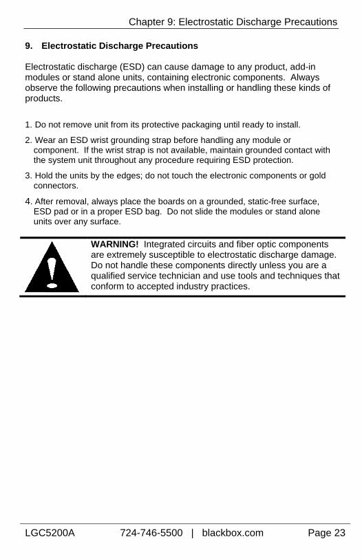
9. Electrostatic Discharge Precautions Electrostatic discharge (ESD) can cause damage to any product, add-in modules or stand alone units, containing electronic components. Always observe the following precautions when installing or handling these kinds of products.
1. Do not remove unit from its protective packaging until ready to install.
2. Wear an ESD wrist grounding strap before handling any module or component. If the wrist strap is not available, maintain grounded contact with the system unit throughout any procedure requiring ESD protection.
3. Hold the units by the edges; do not touch the electronic components or gold connectors.
4. After removal, always place the boards on a grounded, static-free surface, ESD pad or in a proper ESD bag. Do not slide the modules or stand alone units over any surface.
WARNING! Integrated circuits and fiber optic components are extremely susceptible to electrostatic discharge damage. Do not handle these components directly unless you are a qualified service technician and use tools and techniques that conform to accepted industry practices.

LGC5200A Rev. 1 57-80912BB-00 Rev. A1