Conversion of belt-drive VSD fan with EC plug fan for VAV ... · PDF fileThe 7th Greater Pearl...
13
The 7th Greater Pearl River Delta Conference on Building Operation and Maintenance 165 Conversion of belt-drive VSD fan with EC plug fan for VAV AHU system in office building Paul Sat (1), Cary Chan(2), Isaac Tsang (3), Frankie Chan (4) 1. [email protected] 2. [email protected] (1), (2) Hong Kong Green Building Council, Hong Kong. (3) Swire Properties Limited, Hong Kong. (4) Trane Hong Kong, Hong Kong. Abstract Replacement of lighting and chillers would be the most significant major retrofitting works in Hong Kong after the mandatory of Building Energy Code of HKSAR. Over 60% of the central building services energy consumption in commercial office building is served by the central air-conditioning system. More than 50% of the buildings are using AHUs for treating fresh air and supply air. The most commonly fan configuration inside AHU is the motor-belt driven centrifugal fan with frequency inverter installed for variable speed control. Such configuration would consume 30% to 45% of central air-conditioning consumption. Hence, improving fan efficiency is another major retrofitting works for airside system. AHU fan is designed base on the rated condition and its efficiency for one operating point. However, the actual variable speed fan operation would cover a range of operating conditions and efficiencies. The overall efficiency should also include belt, motor and frequency inverter. Hence, Air movement and Control Association (AMCA) has been induced two new Standards foe catering such issues. This paper would demonstrate how to conduct an airside air-conditioning retrofitting work by determining, measuring and verifying the saving through energy performance evaluation approach. Keywords ACMA Standard 205 & 207; HVAC major retrofit; measurement & verification; energy efficiency; performance evaluation.
-
Upload
truongthuan -
Category
Documents
-
view
221 -
download
0
Transcript of Conversion of belt-drive VSD fan with EC plug fan for VAV ... · PDF fileThe 7th Greater Pearl...

The 7th Greater Pearl River Delta Conference on Building Operation and Maintenance
165
Conversion of belt-drive VSD fan with EC plug fan for VAV AHU system in office building
Paul Sat (1), Cary Chan(2), Isaac Tsang (3), Frankie Chan (4) 1. [email protected] 2. [email protected] (1), (2) Hong Kong Green Building Council, Hong Kong. (3) Swire Properties Limited, Hong Kong. (4) Trane Hong Kong, Hong Kong. Abstract Replacement of lighting and chillers would be the most significant major retrofitting works in Hong Kong after the mandatory of Building Energy Code of HKSAR. Over 60% of the central building services energy consumption in commercial office building is served by the central air-conditioning system. More than 50% of the buildings are using AHUs for treating fresh air and supply air. The most commonly fan configuration inside AHU is the motor-belt driven centrifugal fan with frequency inverter installed for variable speed control. Such configuration would consume 30% to 45% of central air-conditioning consumption. Hence, improving fan efficiency is another major retrofitting works for airside system. AHU fan is designed base on the rated condition and its efficiency for one operating point. However, the actual variable speed fan operation would cover a range of operating conditions and efficiencies. The overall efficiency should also include belt, motor and frequency inverter. Hence, Air movement and Control Association (AMCA) has been induced two new Standards foe catering such issues. This paper would demonstrate how to conduct an airside air-conditioning retrofitting work by determining, measuring and verifying the saving through energy performance evaluation approach. Keywords ACMA Standard 205 & 207; HVAC major retrofit; measurement & verification; energy efficiency; performance evaluation.

The 7th Greater Pearl River Delta Conference on Building Operation and Maintenance
166
1 Introduction The HKSAR Government launched the “Energy Saving Plan for Hong Kong’s Built Environment 2015~2025+” in May 2015 with the aim to achieve an energy intensity reduction target of 40% by 2025 using 2005 as the base. Following the COP21, The HKSAR Government launched the Climate Ready @ HK campaign early of 2016 to solicit the building industry’s participation in achieving the carbon reduction targets, One of the key initiatives is to seek commitment by both the Government and the private sector to carry out retrofit and retro-commissioning. About 60% of the central building services energy consumption in commercial buildings is consumed by the central air-conditioning system and other 20% is consumed by public lightings. Hence, replacement of chillers and lighting fixtures would become the most significant major retrofitting works in Hong Kong after the mandatory of building energy code of HKSAR since 2012. Such kinds of measures would contribute about 25% of the energy reduction in commercial buildings. How about another 15% of the target as required by the Energy Saving Plan? There are about 50% of commercial office towers and retail centers which are using air handling units (AHUs) for treating fresh air and supply air. The most commonly configuration of the fan-motor unit of AHU is the belt driven centrifugal fan connecting with induction motor and over a quarter of them are installed with external variable frequency drive (VFD) for variable fan speed control. Such configuration would consume 30% to 45% of the central air-conditioning consumption depending on whether constant or variable air volume system is being used. The use of VFD in AHU fan speed control for energy saving is commonly adopted in commercial office buildings and such kind of technology would be gradually applied in retrial centers. On the other hand, duct static pressure reset for further trim down the static pressure requirement for fan duct system are also gradually adopted by the industry no matter the airside system with or without direct digital control feedback from the VAV boxes [KF Yee, 2002; Lap Yan Lee, 2003; Cary Chan, 2011]. However, the performance of such kinds of advance controls may not well established due to the oversizing of AHU fan and the limitation of low frequency VFD operation for power quality control as required in the Building Energy Code [EMSD, 2015]. Hence, improving fan size and efficiency is another retrofitting work for the central air-conditioning airside system. Replacement of AHU as a whole is not easily conducted in existing buildings as it would cause interruption to the normal day-to-day operation in existing buildings and definitely compliant by the building tenants since most of the AHUs are installed inside the tenant areas or aside from the common corridors. For the replacement of AHU fan, motor and belt, there seems no any significant improvement or evolution for such kinds of elements. In conventional fan-duct design process, constant speed fan is designed base on the rated condition for its operating point and the efficiency is considered solely for the fan itself. However, when using variable speed fan-duct system, the efficiency cannot be

The 7th Greater Pearl River Delta Conference on Building Operation and Maintenance
167
considered for the fan alone, but also included belt, motor and VFD as a whole [Armin Hauer, 2012; Tim Mathson, 2011]. Hence, the Air movement and Control Association (AMCA) has been induced two new Standards, ACMA 205 & ACMA 207 [AMCA, 2012; 2015] in recent years for catering such issues. In addition, the actual operation of variable speed fan is not a single point but a range of operating conditions at various efficiencies. As a result, it is required to evaluate both full and partial load conditions of the fan-duct system efficiency in retrofitting works. 2 Development of plug fans and electricity commutated motors Most of the existing AHUs are using centrifugal fans which are driven by induction AC motors through a belt-puller connection unit (Figure 1). The belt efficiency may not be appropriately designed by engineering approaches [Ron Francis, 1998]. Besides that, deterioration of the belt would not be reviewed in normal operation as a result the performance of the fan-motor system could not be guaranteed. Plug fan system was being introduced in recent years with the advantage of a direct connection between motor and fan impeller as similar to the configuration of motor-pump unit. Such kind of configuration was achieved by making a breakthrough in the aerodynamic design of fan blades for eliminating the obstruction to the air path due to direct integration of fan and motor. Electricity commutated (EC) plug fans is an advance technology which use a brushless EC motor directly connected to an aerial designed impeller (Figure 2).
Figure 1 (left) – Centrifugal fan driven by induction AC motor through belt-puller Figure 2 (right) – Impeller connected to brushless electricity commutated motor
The electronics and brushless DC motors are combined as a single unit and speed control can be simply achieved by varying the control voltage without an external VFD. 3 The overall efficiency of a fan duct system Nowadays, variable speed systems are being used for most of the AHUs in commercial buildings for both fresh air and supply air control. The fan speed may be controlled by whatever means to satisfy both flow rate and static pressure demand of the fan-duct system. However, engineers are almost concentrated on fan and motor efficiency that has already stipulated in the Building Energy Code [EMSD, 2015] such that the system fan motor power required for constant air volume (CAV) and variable air volume (VAV)

The 7th Greater Pearl River Delta Conference on Building Operation and Maintenance
168
air distribution system should not exceed a limit of 1.6 and 2.1 W/l/s respectively. Such criteria may illustrate that VAV may require a higher power to flow ratio due to the consideration of VFD. However, the annotation of such ratio is only considered in the efficiency of fan, belt and motor except VFD in the Technical Guide of Building Energy Code. Besides that, there is no separate requirement on belt and VFD efficiencies stipulated in the Building Energy Code except motor as a result those two components in a VAV fan-duct system is not an engineering focus. 4 The site provision and measurement A 34-floors high rise commercial office building was selected where the whole floor tenant had been decided to move out. Each floor of the building was served by VAV AHU system with direct digital control (DDC) feedback to the building management system for control and monitoring. All the operating data of the airside system were recorded in SQL format at time interval of 30 minutes in the central databank system and the data can be extracted automatically to CSV format in Excel spreadsheet. The data includes flow rate of VAV boxes, degree of opening of cooling coil control valve, fan speed, supply and return air temperature of AHU, static pressure of the fan-duct system and energy power meter for all AHUs of the whole building. The component details within AHU are listed in Table 1.
Table 1 - Component details of AHU Fan Section Cooling Coil Section
Fan speed (rpm) 1016 Total/sensible load (kW) 189.7/171.4
Fan brake power (kW) 16.7 On coil, db/wb(°C) 25.5/17.3
Motor Rating (kW) 22 Off coil, db/wb(°C) 11.9/11.5
Type of drive Belt Chilled water in/out (°C) 6.5/13.6
Chilled water flow (l/s) 6.4
Duct static pressure was maintained at the original set point of 250Pa and static pressure reset control is not activated in this floor. The site measurements were conducted in an unoccupied office area during a short period of time when existing tenant moved out and before the new tenant moving in. The sound pressure level at various point of the office space was recorded by the sound power meter. The result was checked and satisfied with the NC requirement of interior office. In order to obtain data at different performance that cover a wide range of operating conditions, the supply flow demand were artificially control by adjusting the VAV boxes control set point through BMS against the space air temperature [KF Yee, 2002]. Setting the set point 2°C above the space temperature causes the dampers of VAV boxes to reach a minimum opening position while setting it 2°C below the space temperature causes fully opening of damper of VAV boxes. Hence, various demand of supply flow for the AHU can be simulated by different fully and minimum opening of dampers of VAV boxes. The flow rate of VAV boxes would be recorded by the BMS

The 7th Greater Pearl River Delta Conference on Building Operation and Maintenance
169
while the fan speed of the EC-fan can be recorded by a laptop integrated with fan unit. 5 Study the full & partial load performance of the existing belt drive centrifugal fan and EC plug fan Both fan and efficiency curves of the belt driven centrifugal fan were provided in the O&M manual. The fan shaft power (FW) can be determined from the flow rate (Q), fan total pressure (FTP) while the fan efficiency (FE) can be determined by the following equation FW = Q*FTP/FE (1) In order to facilitate the study of the variable speed operating characteristics of the centrifugal fan, the percentage to design of fan total pressure (ftp) and fan power (fw) can be described as a function of percentage to design flow (q) by the following multiple order regression models ftp = a0 + a1q + a2q2 + a3q3 (2)
fw = b0 + b1q + b2q2 + b3q3 (3)
Where ftp = FTP/FTP0, fw = FW/FW0 & q = Q/Q0 Applying fan law to the FTP & FW for determining FTP* and FW* at fan speed N* Q*/Q = (N*/N0) or Q* = Qn (4)
FTP*/FTP = (N*/N0)2 or FTP* = FTPn2 (5)
FW*/FW = (N*/N0)3 or FW* = FWn3 (6)
Where n = (N*/N0) By applying the fan law (4), (5) & (6) to the fan pressure and fan power regression models (2) & (3), we have ftp* = a0n2 + a1q*n + a2q*2 + a3q*3/n (7)
fw* = b0n3 + b1q*n2 + b2q*2n + b3q*3 (8)
Combining (1), (4) (7) & (8), we have
FE* = c0(q*/n) + c1(q*/n)2 + c2(q*/n)3 + c3(q*/n)4 (9) The same principle can also be applied to the EC plug fan with the following multiple order regression models ftp* = d0n2 + d1q*n + d2q*2 + d3q*3/n (10)
fw* = e0n3 + e1q*n2 + e2q*2n + e3q*3 (11) Due to the efficiency of EC plug fan is a combine of fan, motor and VFD, an additional term of q*n was applied to the overall efficiency of the fan-motor unit as below. All the coefficients are summarized in Table 2. FME* = g0(q*/n) + g1(q*/n)2 + g2(q*/n)3 + g3(q*/n)4 +g4(q*n) (12)

The 7th Greater Pearl River Delta Conference on Building Operation and Maintenance
170
Table 2 - Summary of regression coefficient for equation (7) to (12) Equation (7) Equation (8) Equation (9) Equation (10) Equation (11) Equation (12) a0 1.0801 b0 0.3264 c0 2.2352 d0 1.4294 e0 0.6223 g0 1.3985 a1 0.1122 b1 0.7631 c1 -3.1742 d1 0.7709 e1 1.5478 g1 -1.3591 a2 0.0492 b2 0.1272 c2 2.4391 d2 -0.962 e2 -0.6815 g2 0.7791 a3 -0.2697 b3 -0.2314 c3 -0.778 d3 0.1441 e3 -0.0272 g3 -0.2025 g4 0.1016 6 The new standards for controlling fan efficiency Many of the latest energy codes and standards, including ASHRAE Standard 90.1-2013 [John Cermak, 2013], ASHRAE Standard 189.1-2014, International Green Construction Code 2012 and 2015 International Energy Conservation Code, make reference of a fan efficiency classification system known as Fan Efficiency Grade (FEG) [Dustin Meredith, 2014] which was defined in the Air Movement and Control Association (AMCA) published Standard 205 [AMCA, 2012] in 2010. The metrics currently address only the power applied to the fan shaft and told us the impact of fan diameter on efficiency. Increased turbulence and tolerance magnification result in smaller fans operating at a reduced efficiency when compare to a larger fan [Dustin Meredith, 2014]. A single number efficiency would effectively eliminate the use of smaller fan for reducing building energy use as shown in Figure 3 shared area. Besides that, FEG classification number is based on the peak aerodynamic efficiency of a ducted fan separate from its motor and drive. It can also accompanied by an allowable selection range by defining a number of percentage points, such as a 15-point, from peak efficiency Figure 4.
Figure 3 (left) - Fan size vs total efficiency of fan under the FEG classification curve
Figure 4 (right) - Fan minimum efficiency window Afterward, AMCA published Standard 207, “Fan System Efficiency and Fan System Input Power Calculation [AMCA, 2015] in 2015 for calculating fan system input power and overall efficiency. This would include the efficiency of fan, motor, power

The 7th Greater Pearl River Delta Conference on Building Operation and Maintenance
171
transmission and motor controller as well. The Standard can be adopted for carrying out an apple-to-apple evaluation between the overall fan system efficiency between belt driven centrifugal fan and EC plug fan at rated condition. Hence the V-belt efficiency (ηB), the motor efficiency (ηR) and the pulse-width modulated variable frequency drive efficiency (ηVFD) at rated condition can be determined by the following equation as stipulation in the Standard. ηB = 0.96[1 – exp(-(368.6FW)0.19)] (13)
ηVFD = [aLm / (b + Lm) + cLm2] (14) Where ηR, ηVFD can be referred to Table A2 & Table B2 of the AMCA Standard 207 Lm = Motor output / Motor input In order to evaluate the partial load performance of the overall fan system, multiple order regression models as a function of percentage to design flow (q) were developed for the partial load efficiency of V-belt (ηb) and the partial load efficiency of integrated motor and VFD system (ηmc) for a hypothetical system [Andrea Krukowski, 2013] as followings. All the coefficients are summarized in Table 3. ηb = A0 + A1q* + A2q*2 (15)
ηmc = B0 + B1q* + B2q*2 (16)
Table 3 - Summary of regression coefficient for equation (14) to (16)
Equation (14) Equation (15) Equation (16) a 1.018951 A0 0.4698062 B0 -1.208529 b 0.005510 A1 1.3184003 B1 1.9219714 c 1 – a/(b+1) A2 -0.823135 B2 0.2536211 The full and partial load performance curve in percentage of design fan total pressure, fan power and fan unit / overall efficiency were plotted against the percentage of design flow of fan as shown in Figure 5. It can be shown that both belt and motor efficiencies are dropped significantly when the percentage of design flow less than 30%. If the fan is 150% oversized and only required 50% percentage in flow at minimum load condition, both belt and motor would touch with such adverse condition as a result the overall fan-motor system would be dropped significantly. 7 Evaluate and verify the year-round energy consumption of existing belt driven centrifugal fan Making use of the operating data of the airside system recorded in SQL format at time interval of 30 minutes in the central databank, with the data of summation of flow rate of individual VAV boxes for determining the flowrate of the fan and the fan speed; the fan total pressure, fan power and fan efficiency can be determined from the multiple order regression models (7), (8) & (9). The system curve of the fan-duct system can be obtained from the operating data as shown in Figure 6. It was found that a section of system curve was shifted upward due to the unequal pressure requirement of the two

The 7th Greater Pearl River Delta Conference on Building Operation and Maintenance
172
main branches of the air duct system.
Figure 5 (left) - Full & partial load efficiency of motor, belt and VFD
Figure 6 (right) - System curve of fan-duct system of the selected conversion floor
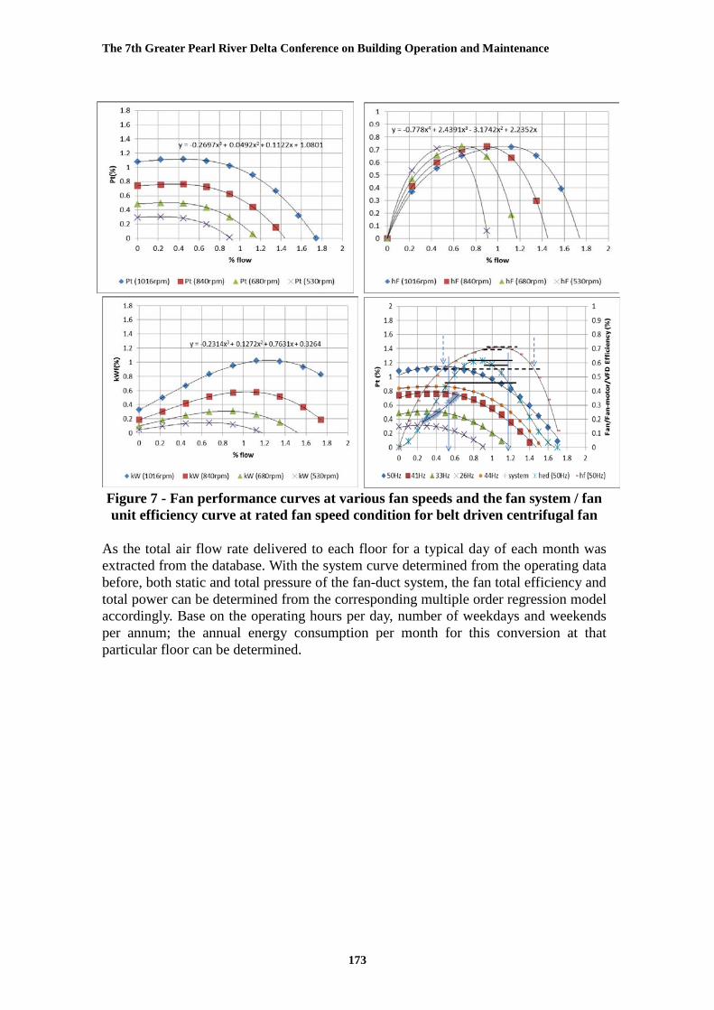
On the other hand, the fan performance curves at various fan speeds and the fan system / fan unit efficiency curve at rated fan speed condition were all plotted on the same graphic as shown in Figure 7 and Figure 8 for the belt driven centrifugal fan and EC plug fan respectively. The fan peak total efficiencies for both types of fan systems were determined. The fan system peak total efficiency for the EC-plug fan is about 78% which is much higher than that of the belt driven VFD centrifugal fan system at 62%. If the operating range is limited to 15% below the fan system peak efficiency, both kinds of the fans with system curves that partially fall within the 15% range as shown in the bottom right corner of Figure7 and Figure 8 with that of the belt driven system is nearly all along the edge of the operation range. It also found that the overall operating range of EC plug fan is wider than that of the belt driven fan. If belt driven fan unit is solely considered, the range can be widened with the fan peak total efficiency at 70%. By using the supply and return air temperature of AHU and the supply air temperature of primary air unit (PAU), the makeup air temperature before coil and the sensible cooling load of the AHU can be determined accordingly. The percentage sensible coil load was plotted against the percentage degree of valve opening of cooling coil as shown in Figure 9 with the slope of the regression line was checked against the sensible heat ratio (SHR) of the cooling coil as determined in Table 1. It aims to verify the accuracy of flow rate summation from individual VAV boxes. Both results are compatible with figures closed to 0.9 in value.
The 7th Greater Pearl River Delta Conference on Building Operation and Maintenance
173
Figure 7 - Fan performance curves at various fan speeds and the fan system / fan unit efficiency curve at rated fan speed condition for belt driven centrifugal fan
As the total air flow rate delivered to each floor for a typical day of each month was extracted from the database. With the system curve determined from the operating data before, both static and total pressure of the fan-duct system, the fan total efficiency and total power can be determined from the corresponding multiple order regression model accordingly. Base on the operating hours per day, number of weekdays and weekends per annum; the annual energy consumption per month for this conversion at that particular floor can be determined.

The 7th Greater Pearl River Delta Conference on Building Operation and Maintenance
174
Figure 8 – Fan performance curves at various fan speeds and the fan system / fan
unit efficiency curve at rated fan speed condition for EC plug fan Due to the energy power meter is only available at the main electrical risers for the total 34 numbers of AHUs in same capacity of the whole building; the monthly average daily airflow of AHUs were determined throughout the year and it was related to the that of the converted AHU in a typical day flow rate at that particular floor as shown in Figure 10. It was found that the monthly average daily flow rate of the office building is about 90% of that of the converted floor. In order to verify the appropriateness of the estimated method, the annual energy consumption of the existing belt driven centrifugal fan of the whole building can be determined by the monthly average consumption of the existing floor multiplied by 34 floors and 90%. It was found that the calculated annual consumption is 12% below that of the actual consumption. The main reason is the deterioration of the belt as reported by the site operator, with the efficiency reduced to about 85% of rated condition. The same approach can be applied to the EC plug fan system.

The 7th Greater Pearl River Delta Conference on Building Operation and Maintenance
175
Figure 9 (left) – %sensible load (Qsen) vs % valve opening
(i.e. SHR of cooling coil) Figure 10 (right) – Monthly average daily flowrate per floor of office tower vs
that of the conversion AHU floor 8 Conclusion The conversion is only required the replacement of the fan section of AHU without the essential of connecting to the building management system. It can enhance the controllability of reducing the fan speed further at light load condition especially the fan is oversized and minimize the maintenance works for belt driven centrifugal fan and the corresponding VFD for the existing VAV system. Duct static pressure reset control can also be applied and even have better performance than that before. Such upgrading work would not cause any interruption to the occupants in existing buildings if it was carried out during the tenant moving out and in period. A total of 395,000 kWh (34%) annual saving in electricity consumption has been recorded in a 34-floors office building as shown in Figure 11 and similar thermal comfort and noise level have been maintained. There are over 700 high riser office buildings in Hong Kong with 20% are using VSD AHU system. We are confident that the same concept can be implemented for such buildings and similar saving potential can be achieved in other commercial buildings. It would yield a saving of about 55,000,000 kWh annually (equivalent to 38,500 tonnes CO2 emission reduction) if the same measure can be taken throughout HK. The saving potential would be about 8% of the reduction target that the Public Consultation on HK’s Climate Change Strategy and Action Agenda has suggested for existing commercial buildings.

The 7th Greater Pearl River Delta Conference on Building Operation and Maintenance
176
Figure 11 – The monthly thermal performance line of airside AHU system of
existing belt driven centrifugal fan system and that of EC-plug fan system 9 Acknowledgement The authors are grateful to Swire Properties Ltd. and Trane Hong Kong for the fully support to the site and equipment provision, the field measurement and the work reported in this paper. 10 References 1. KF Yee, Francis WH Yik, Cary WH Chan, Himson YT Chan, “A Study on the
Energy Saving of Converting A VAV System from Inlet Guide Vane to Variable Fan Speed Control”, HKIE Transaction, Vol.9(2), pp1-7, August 2002.
2. Lap Yan Lee, “Performance of Variable-Air-Volume Air-Conditioning System under Reduced Static Pressure Control in an Occupied Office”, Technical Notes – Building Services Engineering Research and Technology, CIBSE, 2003.
3. Cary Chan, Job Wong, Paul Sat, Jean Qin, “Introducing Duct Static Pressure Reset for Variable Air Volume Systems without Direct Digital Control” Proceeding of the 2nd Greater Pearl River Delta (GPRD) Conference on Building Operation and Maintenance, 2011.
4. AMCA, “ANSI/AMCA Standard 205-12, Energy Efficiency Classification for Fans”, Air Movement and Control Association International, Inc., 2012.
5. AMCA “AMCA Publication 207, Fan System Efficiency and Fan System input Power Calculation”, Air Movement and Control Association International, Inc., 2015.
6. John Cermak & Michael Ivanovich, “Fan Efficiency Requirements for Standard 90.1-2013, ASHREA Journal, pp24-30, April 2013.

The 7th Greater Pearl River Delta Conference on Building Operation and Maintenance
177
7. Armin Hauer & Joe Brooks, “Fan Motor Efficiency Grades in the European Market”, ACMA International in motion (www.ACMA.org), pp14-20, Summer 2012.
8. Tim Mathson & Michael Ivanovich, “AMCA’s Fan Efficiency Grades: Answers to Frequently Asked Questions”, ACMA International in motion (www.ACMA.org), pp8-12, Fall 2011.
9. Ron Francis, “Pushing belt drive efficiency”, PTdesign (www.ptdesign.com), pp33-36, March 1998.
10. Andrea Krukowski & Craig P. Wray, “Standardizing Data for VFD Efficiency”, ASHREA Journal, pp16-26, June 2013.
11. Dustin Meredith & Jeanne Harshaw, “FANtastic! A Closer Look At Fan Efficiency Metrics”, Trane – Engineers Newsletter, volume 43-3, pp1-8, 2014.
12. EMSD, “ Code of Practice for Energy Efficiency of Building Services installation”, BEC 2015, Electrical and Mechanical Services Department, HKSAR, 2015. (http://www.beeo.emsd.gov.hk/en/pee/BEC_2015.pdf)