Conversion of atmospheric electric energy
28
June 9, 1925. 1,540,998 . H. PLAusoN _ - CONVERSION OF ATMOSPHERIC ELECTRIC ENERGY ‘Filed J‘ . 13, 1921 i 12L Sheets-Sheet 1 ‘ WT
-
Upload
tavennerpride -
Category
Engineering
-
view
251 -
download
3
Transcript of Conversion of atmospheric electric energy
June 9, 1925. 1,540,998 . H. PLAusoN _ -
CONVERSION OF ATMOSPHERIC ELECTRIC ENERGY
‘Filed J‘ . 13, 1921 i 12L Sheets-Sheet 1 ‘
WT

1,540,998 H. PLAUSON
'CONVERSION OF ATMOSPHEPIGELECTRIG ENERGY
June 9, 1,925.
ShQets-Sheet “ 2 . _12. Filed Jan. 13, _1921 ‘
IBXYEBIEU?
J

June 9, 1925. ‘ 1,540,998 , H. PLAUSON
CONVERSION OF‘ ATMOSPHERIC ELECTRIC ENERGY
Filed Jan. 13, 1921/1v 12 Sheets-Sheet 5

1,540,998 June 9, 1925. H. PLAUSON
_ CONVERSION OF‘ ATMOSPHERIC ELECTRIC ENERGY
FiledlJan, 15, 1921 12 Sheets-Sheet 4

June 9, 1925. 1,5403% H. PLAUSON
CONVERSION OF ATMOSPHERIC ELECTRIC ENERGY
Filed Jr_ 3, 1921 ' 12 Sheets-Sheet s
June 9, 10925. ' v H. PLAUSON
CONVERSION .OF ATMOSPHERIC" ELECTRIC ENERGY
Filed Jan. 13, 1921 12' Sheets-Sheet e
F1925. _ 2 v
A1 ‘ I A3
4’
i [M 2 21 » v 27
S1 .53 R 7 b
17 16 'S 1* -18 , ‘ S; 1.9
5a _ ‘12 v
' i3. "
24
.75 i8 23 - ‘55 3
, if“ 7551 ‘ _ 2 T I?ffe?fnf'
1% Km m (a
JXWW
1,540,998 I
June 9, 1925. " . ' 7 1,540,998 ' H. PLAUSON ,
CONVERSION OF"ATMOSPHERIC ELECTRIC ENERGY
Filed Jan. 15, 1921‘ ' 12 Sheets-Sheet’? .
13375517317 “HI/WM MW
L“ MM v v ‘ MIQWLFA

June 9, 1925. ' 1,540,998
H. PLAUSON CONVERSICN OF ATMQSPHERIC ELECTRIC ENERGY I
Filed Jan. 13, 1921, - 12 Sheets-“Sheet s
22 _ unu “um
3% g
121
' 1,540,998 June 9, 1925. ~ ' H. PtAUSON .
CONVERSION OF ATMOSPHERIC ELECTRIC ENERGY '
_ I‘ Filed Jan, 15, 1921 12 Sheets-Sheet”?

June '9, 1925. ' 1,540,993; _ H. PLAUSON
CONVERSION OF ATMOSPHERIC ELECTRIC} ENERGY
:Filed Jan. 1921; 12 Sheets-Sheet 1o
1578-51-57‘ ‘Hill/WWW; mglo/m'mv‘
Ah

_ H. PLAUSON
CONVERSION OF ‘ATMOSPHERIC ELECTBiC ENERGY
Z Z‘ B)
“an " ~
. ~ v “sh ~1~ FlleolqimI 1 2.1 2 q es ‘a

June 9, 1925. 1,540,998 H PLAUSON
CONVERSION OF'ATMOSPHE'R‘IC ELECTRIC ENERGY
E “351
. v :. Foouoolllilr: 8 E
L .
/ [MAW

past-ea Jane is, 1925., v' > ‘
i‘ . ‘UNITED
v‘ > ‘1540,998- ‘ '
_ 31-13mm PLAUSON, orrnaarnune," GERMANY. Z . ‘
summaries armosrnnnic intn'c'rnrc ENERGY.’ Application ?led ianuaryilla, ‘19421, _s¢ria1,1t6;"4'§7,1'07. 7 i
J '0 all whom it may concern.- - Be it known that I, HnRMAisN Pinrmtnv,v
. Esthonian subject,- residing in Hamburg, "Germany, have; invented certain new ‘and useful Improvements .1n .the Conversion of Atmospheric Electric Energy, of which the,
- ~fo1lowin'g is a speci?cation.‘
10
'- or anchored kite balloons ‘made of vfabricsi "and ?lled with hydrogen, are in theory val- -‘
Methods‘of obtaining atmospheric elec-l' tricity by means of metallic‘nettings set with spikes which ' are held .by, means of ‘ordinary
readyknown. _ Atmospheric electricity ob taincd in this way 'hasbeen suggested to‘be' used in theform ‘of direct-currentfor-the ‘charging of accumulators. - This knowledge 1 however is' at present only theoretical asthe
' conversion in practice has hitherto been a
120
Y . non-conducting materials which are liableito’, _ ,be \tornandare' permeable to the gas; 1t>1s 30
failure. vNo. means are-known of protecting the apparatus from'destruction by lightning, The‘- balloons used ‘for ‘collecting the charge
' must also be made-of veryzlarge size in order , v' to be able tofsupporttheweight of theme-Y 5 tallic netting and the heavy .jcablei’conn‘ece?
ti'ons. t Instead 'ofusingheavy metallic netting -
collectors attached‘ to single-air b'alloonsiof
proposed to use metallic balloon collectors which have ‘the following important advan tages; - ' ‘ " i ‘ ‘
.4 ' (a) The metallic casesqam impenetrable
-- '35
" - faces.
40
to h'elium‘and hydrogen; the also represent; collecting sur large metallic ‘weatherfproo
(1))‘ Radio active-means andthe likeniay ‘be easily applied internally or externally; whereby the ionization is considerably 1n-4 ' c'reased and therewithalsothe quantity
. atmospheric 'electricitycapable ofV'be-ing col lected' 4 . _ ,
(1:) Such balloon Collectors of light-metal dot not require to be of large size as they
45 have to carry only their own “moderatev weiglit,_an_d that of. the conducting cable or wire... I The entire system therefore o?'érs lit
and is resistant and stable.‘ 60" tle- surface for the action-of storm and’ wind 5
I (‘6) Each balloon can'be easily raised and ' loweredby means of a Winch so that all re, pairsyrechalrging andthe like can becarried 'wtQWithOUt danger vduring] the operation.“
“scribed with reference to‘
It further proposedto use'a collecting aerial network of several separate collectors ‘spread out inthe air. above the earth, which
conductors.v - ~According to this'invention charges'of .at-j
l‘mospheric electricity are not directly‘con _ ._
verted into mechanical energy,‘ band, 'this'; ‘ -
forms themain di?’erence from'previjousin ' ‘ ventions, butthestatic electricity which ru to ‘earth through aerial. conductors~_ ini . form of. direct ' current of very} high =volt8ge
and ' low current strength "is .jconvertedlintq ‘__-electr-o-dynamic energy in the formjof-Tfhi'gh frequency vibrations. "Many advantagesare ' "
. I
toi‘y' circuits it is possible ‘to obtain'elect/ro ‘magjnetic waves of’ various amplitude‘ and‘ g . ~, "thereby to increasethe degree ofresonance: " y of such current. . Such ‘resonance ‘allows va- 51°‘ .
thereby obtained and. all,‘ ‘disadvantages ,avoided,~ -._l y “ ., Thev very‘high voltage of staticelectricity of. a‘ low ‘current. strength'can' be‘ converted'l I .'
by this invention to‘ Voltagesmoré isuitableir’f for technical vpurposes and of‘ greater "cur-fv
‘rent strength. _ B'y- the'use ofg-closedoscillas
70
rious' values _- of inductance to be chosen" whereby ‘again ‘the ‘governing of the starting Y and stopping of machines‘ drivenltli-ereby‘lby‘ ' I simply ' tuning the. resonance between coils of the machine and thetransformer'circuit ‘forming the resonance’, can. ‘easily be ob-'
85..
tained. Further, " such‘ currents have the. - property‘ofjbeiiig directly.- available for va
? rious uses; even without employing them for driving motors, of whichtliere may-be par 90- .
ticularly mentioned, ‘lighting, production of ‘_ heat and use .in electro-cheniistry._ I. _.
Further,iwith,_ such currents a‘, series of ap paratus may be _§ fed without ‘directv current supply through conductors'and also the
‘ electro-magnetic high >frequency'i‘currents' may be converted by means of'special motors adapted for electromagnetic oscillations
-.- into-‘mechanical energy," or finally converted I by special'macliines into alternating current of low frequency or ‘even into direct current ofhigh potential. ' ' ‘ '
160'
. The invention is more_'parti¢;-.ularly de-’ l the accompanying
diagrams in which , v _ , ~ '_ -'
Figure 1 is'an explanatory. ?gure. " Figure 2‘ is
105
[i
collectors are; interconnected’ by electrical ‘
a I '
I _‘ jaidiagrammatic view-‘ofthe }. ‘ ‘
simplest form." I ' - ' ~ -

10
15
30
2
Figure 3 shows a method of converting ‘atmospheric electrical energy for use with motors. ‘ '
Figure 4 is a diagram showing the use of protective means. , ' .
Figure 5 is’ a diagram of an arrangement for converting large ‘current strengths.
. Figure 6 is a diagram of an arrangement including controlling means. '
, Figure 7 ‘shows means whereby the spark gap length can be adjusted. ’ _ Figure 8 shows a unipolar connection for
the motor. _
Figure 9 shows a weak coupled system suitable for use with small power motors. Figures 10, 1.1 and 12 show modi?ed ar
ran ements.- '
Flgure 13 shows a form of inductive cou~' pling for the‘motor circuit.
Figure 14: is a modi?edform of Figure 13 with inductive coupling.‘ ‘ '
Figure 15 is an arrangement with non inductive motor.' 7 Figure 16 is an arrangement with, cou
pling by condenser. _ ' I _
Figures 17 ,- 18 and 19 are diagrams of fur ther modi?cations. ' _
Figure 20 shows a simple form in which the aerial network is combined‘ withspecial collectors. ' I
Figure 21 shows diagrammatically ~an ar rangement suitable for collecting large quantities of energy. , .
Figure 22 is a modi?ed arrangement hav ing two'rings of collectors.
Figure 23 shows the connections vfor three" rings of collectors. . -
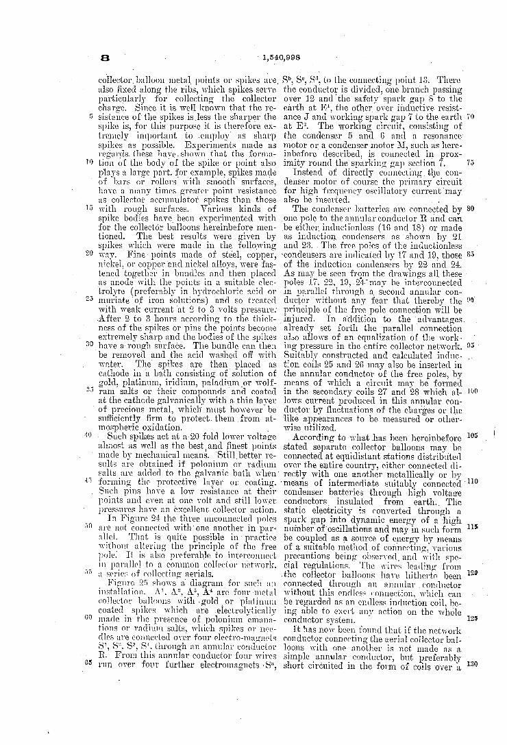
Figure 24 shows a collectingballoon and diagram of its connection of condenser bat teries. ‘ ~ _
Figures 25 and 26 show modi?ed collector balloon arrangements. I _
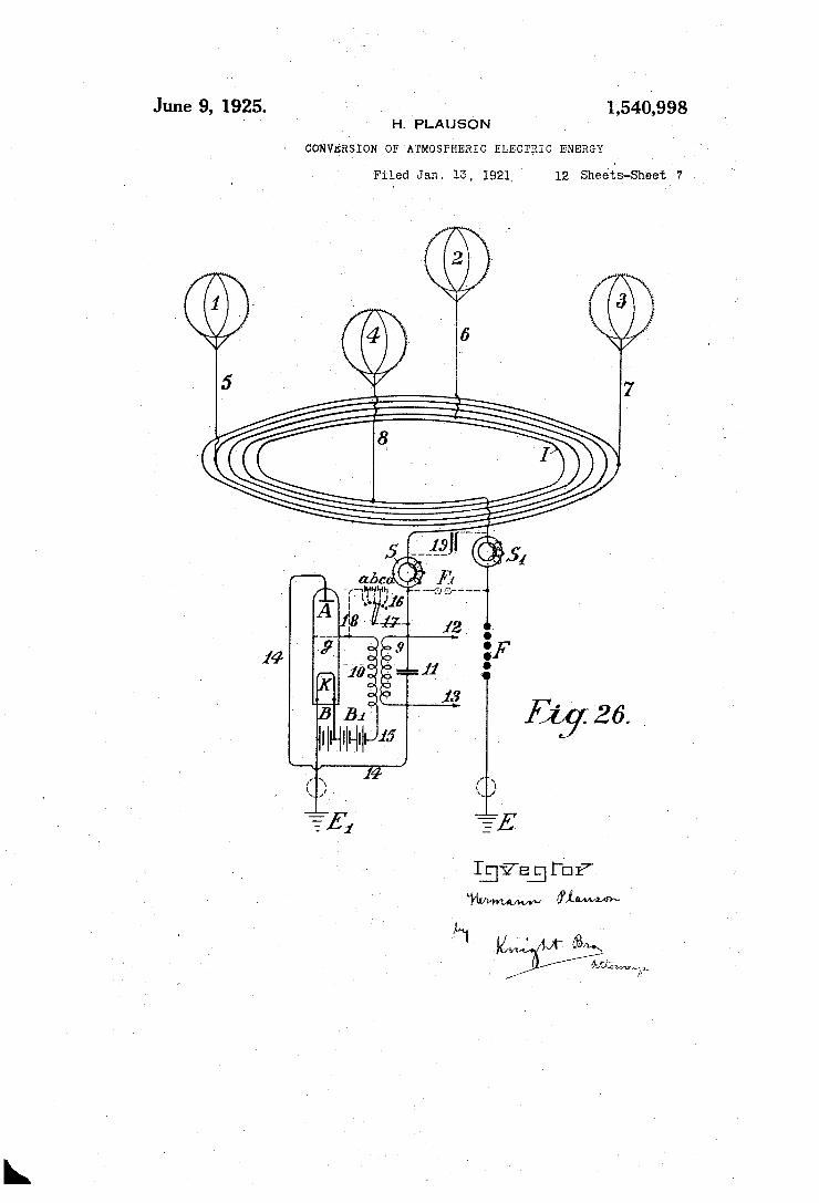
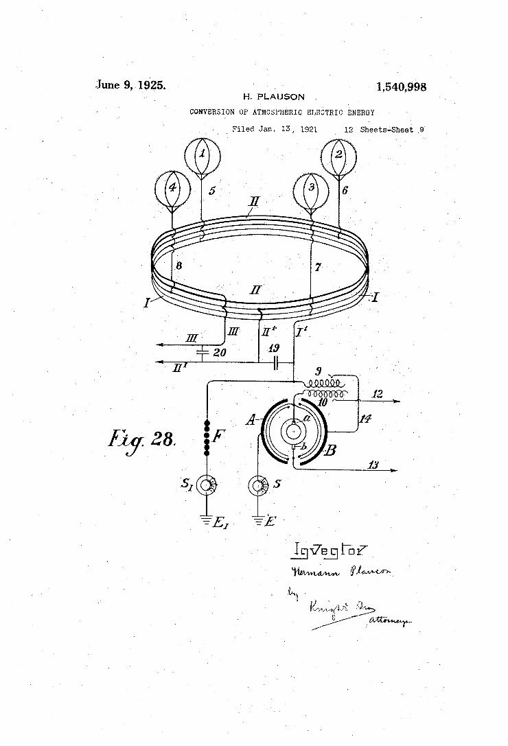
Figure 27 shows a second method of con necting conductor for the balloon aerialsp Figure 28' shows an auto-transformer
method of connection. > . > ‘
Figure 29 shows ‘the simplest form of con struction withv incandescent-cathode. _ Figure 30 shows a ‘form with cigar shaped
_ balloon.
- Figure 31 is a modi?ed arrangement. _ Figure 32 shows a form with cathode and
electrode enclosed in a vacuum chamber. Figure 33 is a modi?ed form of Figure 32. Figure 34 shows an are light collector. Figure 35 shows such an arrangement for
' alternating current. ,
60
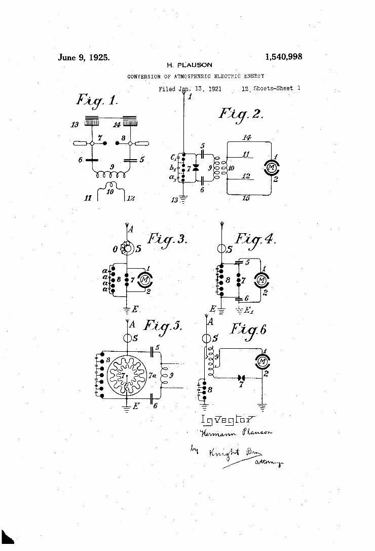
Figure 36 shows an incandescent collector with Nernst lamp. _ .1 Figure 37 shows a form with a gas ?ame. Figure 1 illustrates asimple diagram for
converting static electricity into dynamic energy 0 a high number of oscillations. For the sake of clearness in the‘drawings an in?uence machine is assumed to be employed
1,540,998
and not an aerial antenna. 13-and 14 are combs for collecting the static electricity or", the in?uence machine. 7 and 8 are spark discharging electrodes, 6 and 5 condensers, 9 an inductive primary coil, 10 secondary coil, 11 and 12 ends of conductors of the sec 7ondary coil 10. When the ‘disc of the static in?uence machine is rotated by mechanical means, the combs collect the electric charges one the positive and the other the negative, and charge the condensers 5 and 6 until such ahigh potential is formed across the spark gap F——8, that the spark gap is jumped. As the spark gap 7——8 forms a closed circuit with condensers 6 and'5, and inductive re sistance 9, as is well known, waves of high frequenc electromagnetic oscillations will ‘pass in t is circuit. ,
The high frequency. of the oscillations produced in the primary ‘circuit induces waves ‘of the same periodicity in the sec ondary circuit. Thus in the primary cir cuit electromagnetic oscillations are formed by the passage of the spark over the spark gap and these waves .are maintained by fresh charges of static electricity. By suitably selecting the ratio between the
number of the coils in the primary and ‘sec ondary circuits with regard to a correct ap
, o \ I v .
_pl1cat1on ofthe co-e?icients of resonance .(capacity, inductance, and resistance) the high voltage of the primary circuit may be suitably converted into low. voltage and high current strength. . _
p. When the oscillatory discharges in the pri mary circuit becomes weaker Or entirely cease, the condensers are charged again by the static electricity until ‘the accumulated charge again breaks down the spark gap.. All this is repeated as long as electricity is produced by the static machine by employ ing mechanical energy. ' An elementary form ofqthe invention is
shown in Figure 2 in which two spark gaps in parallel are used one of which may be
_ termed the working gap 7 in Figure 2. whilst the second serves as a safety device for ex cess voltage and consists of a larger number of spark gaps ' than the working section, which gaps are arranged in series and are bridged by very small capacities as is illus trated in a1, 1),. 0,, Figure 2 which allow of uniform sparking in the safety section. In~Figure 2 A is the aerial antennafor
collecting charges of atmospheric electricity. 13 ‘is the earth connection of the second part. of the spark gap, 5 and ,6 are‘condensers, 9 a primary coil. Now when through the aerial
_. A the positive atmospheric electricity seeks to combine with the negative charge to earth, this is prevented by (the air gap between) the spark gaps. The resistance of the spark. gap 7 is, as shown in the drawings, lower than that of the other safety section which consists-of three'spark gaps connected in
S0
DU
100
105
110
120

' ‘ 1,540,998; -.
series,'and cdnsequentl , a threetiinesgreater' > air resistance is offere by ‘the latter. ' '
So long‘ therefore, as the resistance of ‘the spark gap 7 is not overloaded, so .that the other spark gaps have an equal resist- '
- ance with it vthe discharges take place only? over spark gap , 7. Should~ however the
- . ,volta e be'vinorease'd by any in?uences so ,that‘ it might .be dangerous for charging
' ' > Without-this secondv spark gap, arranged‘
‘so
the condensers 5 and 6 or for: the coil in? sulation 9 and 10 in. consequence of break 1
' down,- by a' correct regulation of thisspark ' a ' ap the second spark» gapcan discharge free
' Iron; inductive e?'ects direct to earth with-. out endangering the machine.
in‘ parallel having. a‘ ,higher resistance than ‘the-working spark gap it is impossible to collectandrender available large quantities“ . _ _
' » - = I ' r‘ . charges.will~_~for the sake ofsimplicity be
diagrammatically indicated by two semi~ of electrical energy; _ _ l ‘ H,‘ _
v The action ‘of this'closed oscillation c1r_ ‘ cuit "consisting “ofsparkp‘gap. 7 , two condens _ers'5 and 6, primary coil 9, and also sec;
. yondar'y. coil ‘10 is exactly the. same as the one described in Figure‘ 1 with ‘the arrange-5 ment of the static induction machine with the, only di?'erence that here,’ the second‘
' spark gap is provided. Theelectromagnetic
30 ‘high frequency alternating current obtained can be tapped o?' fronr the conductors'll. and 12 -_for lighting and .heating. purposes. Special ‘kinds of motors adapted for work ing‘ with “ these peculiar‘- electrical charges
ll'fmay be connected at 14: and I? which can
‘high frequency oscillations. ' work with static electricity charges or‘ with
In addition ‘to ,the- use of spark ‘gap-s; ’ i in parallel a second measure of security is
40
‘_ ; invention, in the introduction of and method . ‘- 'of connecting‘ certain protective electro
also necessary for taking off the current.‘ .This precaution consists according to this
magnets or choking coils in the aerial. cir
:45
"50
55
cu'it' as shown by S’ in Figure'3. A single electremagnet only having a core
of the thinnest possible separate laminations'. is c'onnectedwith the aeriaL. In thecase ‘of high voltages in the aerial 1'
network or at places where’there ‘are fre quent thunder storms, several .such magnets may however‘ be connectedin series. 'In ‘the case of large units‘or plants sevi
eral electromagnets can be employedlin par- ' _ allel or in‘seriesparallel. ' ‘ '
__Thé‘_ windings of these .electromagnets maybe simply connected‘ in‘ series‘ with. the aerials.- In this case the winding-preferably
'- consists of several thin parallel wires, which, make up together, the necessary'section. .. _The winding may be _made_ of primary
and secondarywindingsin the. form of a ‘transformer. The primary 'windingwill be then connected. in series with the aerial net work, and the secondary winding more’ or‘
.less SllOl‘t-‘CIY‘CU‘ItGCl over a regulating res1st-'
.rectivon' as the direct current. ‘progress is arrested‘ by two "sparks gaps
:ance or an induction ‘coil. In the‘flatterv caseit'ispossible to regulate to, a certain
the, further. descriptiona ‘of ' the‘ connecting and constructional-diagrams the aerial elecs
in
extent the ‘effect ,of the chokingcoils; 5111 ‘i _ i
tromagnet choke‘ coil‘ is indicated by a ' simple ring S. _ ' . '
*, Figure 3 shows the simplest way of con- 1 vverting atmospheric electricityinto electro -_magnetic wave'energy by‘ the use of special .75.‘, motors adapted for high. oscillatory. c'ur- . j rents or_‘stati_c charges of electrical energy. Recentvimprovements ‘in motors ‘for ,work- A‘
'iingi'with static charges and motors Working by resonance, that is to say, having groups of tuned electromagnetic cooperating cir
.cuits render- this possiblebutsuch do not form part of the. present invention.’ 1 -. . A motor adapted to operatejwith static
circles land 2' and therotorof the motor by a ring M. (Figure 3.) .A is a vertical aerial or aerial‘ network». "IS ‘the safetyv chokenor' electromagnet with‘ coil 0 as ‘may be seen'iis connected-with the aerialfA. Ad—
80
9.0 '
jacent the electromagnet‘"_S the aerial-con‘- _' ductor is dlvlded into three, circuits, the
‘.circuit‘» 8 giving the safety spark gap, the circuit 7. with the working spark gap, and then a circuit including‘ the stator ‘terminal .1, the rotor and‘stator terminal 2 at which a connection is made to the earth wire. The
' two spark gaps. are v also connected metal-' li'cally with the earth wire. ‘The. method of
' working these diagrams is as follows: ' The positive atmosphericg'electric charge
collected tends to COIIIblIIGLWIth the negative electricity (or earth electricity) ‘connected -with the earth wireiv" It travels along the ' aerial _A through‘ vthe electromagnet ' S with o'utbeing checked as it ?ows i‘n'thesai'ne dij
Further, its
placed‘ in the ‘.way"v and the stator. condenser surfaces. ‘The stator condenser surfaces are
.. charged until the’ charge is, vgreater than ' the resistance of the spark gap-7, whereupon a spark springs overthezspark gap)?’ and an " oscillatorylcharge is obtained as by means" “of the motor M, stator. surfaces 1 and'2, and .spark vgap 7, a” closed oscillation circuit'is' obtained for‘, producingthe electromagnetic
' oscillations. ‘The motor here forms the ca- v pacity and thene'ce'ss'ary inductance and re sistance, which, as is well known, are neces‘ sary for converting static electricity into . ' electromagnetic wave energy.» ' l
The discharges ‘formed are "converted into mechanical energy in special motors and ‘can not reach the aerial network by reason of
tends t6 ?ow toearth, a counter _voltage is
."the electromagnet orjchoke. If, however;v . ' when a ‘spark springs over the spark gap '7. a‘ greater quantity of atmospheric electricity - I
130 '

induced in the electromagnet, which is greater the more rapidly and strongly the ?ow of current direct to the earth is. By
I - the formation of this opposing voltage a
10
is.
20
25
su?iciently high resistance is offered to the ?ow of atmospheric electricity direct to earth to prevent a short circuit with the~ earth. a > ' . . .
The circuit containing spark gap 8 having a different wave length which vis notin reso— nance with the natural frcquency of the motor, does ‘not endanger the motor and serves as security against excess voltage, which, as practical experiments have shown, , may still arisein certain cases, but can be conducted direct to earth through this spark gap- ‘ ,
In the diagram illustrated in Figure 4 the spark gap 7 is shunted across condensers 5 and 6 from the motor M. This construction atl'ords mainly a better insulation of the motor against excess voltage and a uniform excitation through .the spark gap 7'. In Figure 5 a diagram is illustrated for
transforming large current strengths which may be employed direct without motors, for example, for lighting or heating purposes. The main difference is that here the spark gap consists of a star shaped disc 7 which can rotate on its own axis and is rotated by a motor opposite similarly ?tted electrodes
. 7“. “Then separate points of stars face one
35
60
another, discharges take place, thus forming an oscillation circuit over condensers 5 and 6. and inductance 9 for oscillatory discharges. It is evident that a motor may also be di rectly connected to the ends of the spiral 9.
The\construction of the diagram shown in Figure 6 permits of the oscillation circuit of the motor being connected-with an in duction coil. Here a regulating inductive resistance is introduced for counter-acting excess voltages in the motor. By cutting the separate coils 9v (coupled inductively to the
' 1 aerial) in or out the inductive action on the motor may be more or less increased or variable aerial action may be exerted on the oscillation circuit. ' ‘~ -
\ In Figure the oscillation circuit is closed through the earth (E and E1). The spark gap 7 may be prolonged or shortened by more or fewer spark gaps being successively connected by means of a contact arm 7*’. Diagram 8 shows a unipolar connection of
the motor with the aerial network.‘ Here two oscillation circuits are closed through the same motor._ The ?rst oscillation circuit passes from aerial A through electromagnet S, point :0, inductance. 9a to the earth con denser 6 and further, over spark. gap 7 to the aerial condenser 5 and back to m. The second oscillation circuit starts from the aerial condenser 5 at the ‘point :01 over the inductance 9 to the earth condenser .6 at the point its and through the condenser 6 over
. 1,540,998
the‘ spark gap 7 back to $1. The motor itself is inserted between the two points of the spark gap 7. From this arrangement slight ly damped oscillation wave currents are pro duced. . ‘ _
In the diagram illustrated in Figure 9a loosely coupled system of connections is il lustrated which is assumed to be for small motors for measuring purposes. A indi cates the aerial conductor, S the electromag net in the aerial conductor, 9 the inductance, 7 the‘ spark gap, 5 and 6 condensers, E the earth, M the motor, and l and 2 stator con nections ‘of the motor. The -motor is di rectly metallicallv connected with the oscil lation circuit. ‘ V, i‘
In Figure 10a purely inductive coupling is employed for the motor circuit. The mo tor is connected with the secondary wire 10 as maybe seen in Figure 11 in a somewhat modi?ed diagram connection. The same applies to the diagram of Figure 12. The diagrams'hitherto described prefer- i
ably. allow of motors of small and'medium strength to be operated. For large aggre gates, however, they are too inconvenient as
70
80'
90
the construction of two or more oscillation . circuits for large amounts of‘ energy is di?i cult; the governing is still more ditlicult and the danger in switchingr on or off is greater. - '
i A means of overcoming such difficulties is shown in Figure, 13. The oscillation circuit here runsstarting from the point a: over con ‘denser 5, variable inductance 9, spark gap - 7 and the two segments (3’- and 4“) form ing arms of a VVheatstone bridge, back to :22. If the motor is connected by brushes 3 and 4 transversely to the two arms of the bridge
lUU
as shown in the drawings, electromagnetic" oscillations of equal‘ sign are induced in the stator surfaces 1 and 2 and the motor does not revolve. 4 are moved inv common with the'eonduct ing wires 1 and 2 which connect the brushes with the stator poles a certain alteration or displacement of the polarity is obtained and the motor commences .to revolve. The maximum action will result if one
If however, thelbrushes 3 and‘
110
brush 3 comes on the central sparking con~ 5 tact 7 andajthe other brushfll on the part 00. ' They are however, usually in practice not brought-on to the central contact 7 but only held in the path of the bridge segments 4“ and 3’1 in order not to connect the spark gaps with the motor oscillation circuit.‘ ' As however, the entire oscillation energy
. can thereby not act on the motor it is better to carry out the same system according to the diagram 14. The diagram 14: differs from the foregoing only‘ by the motor not being directly metallicallv connected with the seg ments of.the\ commutator, but only a pri mary coil 9 which induces in a secondary coil 10, current which feeds the motor M and takes the placeof the rotor. By this
120

' “40,998 ‘ .
arrangement a good transforming action is . obtained, asloose coupling and also an. os_-"
5
cillation circuit without a spark gap. - - In Figure 15 the motoris not purelyin-f-l
ducti'vely as in lllybutv directly‘ metallii'cally branched off‘ from the primary‘ ‘coil \(at m and $1) after the principle of the auto-trans formerfy , V In Figure 16 instead ‘of an inductance a ‘condenser. 6 is in similar manner,"and ‘for’ the same object inserted , between" the._ seg: ments 3*‘ and 4;“. This has the advanta _ ‘that the segments 3“ and 4“ need not; ‘ f ade of solid metal but may'consist. of spiral coils" whereby .a more exact regulationlis possible . v p
., surface's'of the motor, 5.'a condenser battery, ‘ ‘and further motors of high inductance-may 'be employed.v -, ‘ a
The arrangements vof'i'Figures 1.7, 18 and 19 may be employed for use with resonance‘ ‘and particularly with induction condenser motors; between the largeistator induction
_ condenser surfaces,‘ small reversing pole con "densers are connected, which, as may be‘ ‘seen from Figures 17-, 18 and 19 are led together to ‘earth. Such reversing poles __have_the advantage that with large quantities I of electrical energy the spark formationv be‘ tween the separate oscillation circuits ‘ceases.
‘Figure. 19 shows a _,further.method which prevents electromagnetic oscillations of high number of alternations formed in the oscil lation circuit striking. back' to the aerial con-. ductor. It is based .on the wellknown prin ciple that a mercury lamp, one‘ electrode of
35 which is formed of mercury, the other of solid m'etalsuch as steel'allows an electric cliargeto pass .in only one direction from the mercury to the steel and not vlce versa, The‘ mercury electrode‘ of the vacuum tube
40
65
N is therefore connected with the aerial‘ conductor and the steel velectrode with the oscillation circuit. ‘} From this. it- results that charges can pass'only from the aerial through the vacuum tube to the oscillation circuit, ‘but not vice versa. “Oscillations iwhi'ch are formed on being transformed in‘ the oscillation circuit cannot‘ pass .to the aerial conductor. , - v i
In practice these vacuum tubes must be connected behind an electromagnetas the latteralone a?'ords ‘no danger of lightning. _ As regardsthe use of spark gaps, all
arrangements as used for Wireless teleg raphy may be used.‘ Of course the spark gapsin large machines‘ must’have. a su?i cientlyi‘large surface. In very large stations they are cooled in liquid carbonic‘a-cid or bettcrstill in liquid nitrogen or hydrogen; in most cases the cooling may also take
, place by means of lique?ed low homologues of .the’metal series or by means of hydro carbons the freezing point'of which lies at between ~90° C. and ~40° C‘. The spark gap casing must also be insulated and be of
protection against the
, the operation ,walls.‘ . ‘ -
- nectiongrun. '
sheaths preferably _ ‘magnesium alloy, and'are ?lled with hydro
' geno‘r‘helium' and are attached'to copper “plated ‘steel wires. ‘is ‘selected; so that the actual weight ofthe
K
'suilicient strength to'beiable ‘any... pressure which may arise; Any undesirable excess super~pressure which may be formed must be automatically’ let off.v I‘ have‘e'm- " ‘ ployed with very good‘results mercury elec;
acid,‘ the cooling being maintained during
.\ Figure 20 isoiieQ‘f-the simplest farms or ' copstructionl ,of ‘anaerial network in com“-v
.x-sh‘inati'on with collectors, transformers and the like illustrated‘diagrammatically. ' E is.
70 \
"trodes which were frozen. in liquidearbonic '
from/‘the outside-through the i
here ‘the earth ‘wire,’8'the-‘safety'sparka gap, - 7_ the working spark ‘gap, land 2 .the stator
S the protective magnet which is connected with the coil in- the aerial conductor, A1- to? A1". aerial. antennaejwith collecting balloons, ‘ I i
. N horizontal collecting or connecting wires from which, to the centre a number’ of con
The'fjactual collectors consist ‘ of , metal
The size of theballoon ‘
balloon "and-the weight of the conducting‘ vwire is supported thereby. On the .top of the balloon aluminium spikes, made and gilded‘in a special manner hereinafter ,de-. I ' I
scribed, are arranged in order to produce-a conductor- aClllOIl.‘
80
as".
made of an aluminium. " 90
95.
_ _ v ‘ Small quantities‘ of‘
radium preparations,“ more particularly f 100 polonium-ionium or mesothorium' ;prepara-' -, tions "considerably increase the ‘ionization, and therewith the action of these ‘collectors.
loons which are super?cially metalcoat‘ed" according to :Schoop’s metal spraying proc-‘ ess, may however also be employed; A'
‘ ?'- In addition to~ metal balloons,‘ fabric bal-f .» 4 105
metallic surface‘may also be produced vby f lacquering with ‘metallic bronzes, preferably 'accordingto Schoop’s spraying process or lacqu'ering with metallic bronze powders in > _ _' two electrical series‘ of widely different metals, because therebythe collecting effect is considerably increase . _- _ I ' ,
\ Instead of :the ordinary round balloons, elongated?cigar shaped ones may be em
> ployed.v 1 In order also to utilize the fric tional energy of ‘the wind,“ patches or strips of non~conducting ‘substances which pro duce electricity by friction, may be attached to the metallized balloon surfaces._' The wind will impart a portion of its‘energy in the form .of frictional electricity, toithe balloon casing, and thereby the collecting effect is substantially increased. ’
' In practice however, very high towers’ (up to ‘300 metres is fully admissible) may be employed as antennae. In these towers
110,
115
120
125
copper tubes rise freely further above the‘. top of the tower. A gas lamp secured

against the wind is then lit at the point of the copper tube and a- netting is secured to
p the copper tube over the ?ame of this lamp
20
IO c1
30
,nected with a horizontal, conductor.
to form a collector. The gas is conveyed through the interior of the tube up to the summit. The copper tube must be abso lutely protected from moisture at the place at which'it enters the tower and also rain must be prevented running down the walls of the tower which might lead to a bad catastrophe. This is done by bell shaped en largements which expand downwards, being arranged in'the tower in the form of high voltage insulators of Siamese pagodas.
Special attention must be devoted to the foundations of such towers. They must be well insulated from the ground, which may be obtained by ?rst embedding a layer of concrete in a box form to a sufficient depth in the ground and inserting in this an asphalt lining and then glass bricks cast about 1 or 2 metres in thickness. Over this in turn there is a ferro-concrete layer in which alone the metal foot of ‘the tube is secured. This concrete block must be at least 2 metres from the ground and be fully protected at ‘the sides by a wooden covering, from moisture. In the lower part of the tower a wood or glass house for the large condenser batteries or for the motors mayr be constructed. Iniorder to lead the earth connection to the ground water, a well in sulated pit constructed of vitreous bricks, must be provided. Several such towers are erected at equal distances apart and con
The ‘ horizontal connecting wires may either run
'40
directly from tower to tower or be carried on bell shaped insulators similar to those in use for high voltage conductors. .The width of the network may be of any suitable size' and the connection of the motors can take place at any suitable places. In order to collect large quantities of‘
electricity with few aerials it is .well to pro vide the aerial conductor with batteries of condensers as shown in two methods of con? struction in Figures 21 and 22. In Figure 2l-the batteries of condensers 5 are con nected on the one hand with the aerial elec-v tricity collectors Z by the aerial conductor
‘ A, and on the other hand interconnected in
60
series with an annular conductor from which horizontal conductors run to the con necting points C to which the earth wire is connected. I .
Figure 22 shows a similar arrangement. Should two such series of antennae rings be shown by a voltmeter to have a large dif ference of potential (for example, one in the
‘ mountains and one inthe plain) or even of different polarity these differences may be compensated for by connecting sufficiently large condenser batteries (5, 5“, 5") by means of Maji star- conductors D and D1. In Fig
me 23 a connection of three suclri'ings of collectors to form a triangle with alcentral condenser battery is illustrated. ‘ The condenser batteries of such large in
stallations must be embedded in lique?ed gases or in liquids freezing at very low temperatures. the atmospheric energy must be employed for liquefying these gases. It is alsoprefer ablelto employ pressure. By this means the condenser surfaces may be diminished, and still allow for large quantities of energy to be stored, secure against breakdown. For smaller installations the immersing of the condensers in well insulated oil or the like, su?ices. Solid substances on the other hand cannot be employed as insulators. The arrangement in the diagrams hitherto
described was always such that the con denser'batteries were connected with both poles directly to the aerial'conductors. An
In such cases a portion of .
80
improved diagram of the connections for v obtaining ‘atmospheric electricity for the condenser batteries has however, been found to be very advantageous, this arrangement consists in that they are connected by only one pole (unipolar) to the collecting_net work. Such a method of arrangement is very important, as by means of it a constant current and an increase of the normal work ing pressure or voltage is obtained. If for example a collecting balloon aerial which is allowed to rise toa height of 300 metres, shows 40,000 volts above earth voltage, in ‘practice it has been found that the working voltage (with a withdrawal of the power according to the method hereinbefore de-_ scribed by means of oscillating spark gaps and the " like) is only about 400 volts. If however, the capacity of the condenser sur faces be increased, which capacity in the above mentioned case was equal to that of the collecting surface of the balloon aerials, to double the amount, by connecting the condenser batteries with only one pole, the voltage rises under an equal withdrawal of current up toy and beyond 500 volts. This can only be ascribed to the favourable action of the connecting method.
In addition to this substantial improve ment it has also been found preferable to insert double inductances with electromag nets and to place the capacities preferably between two such electromagncts. It has also been found that the useful action of such condensers can be further increased if an induction coil be‘ connected as inductive resistance‘ to the unconnected pole of the condenser, or still better if the condenser itself be made as an induction condenser. Such a'condenser may be compared with a spring which when compressed carries in itself accumulated force, which it again gives off when released. In charging, a charge with reversed sign is formed at Hw
90
95
inc

‘14)
to
' 1
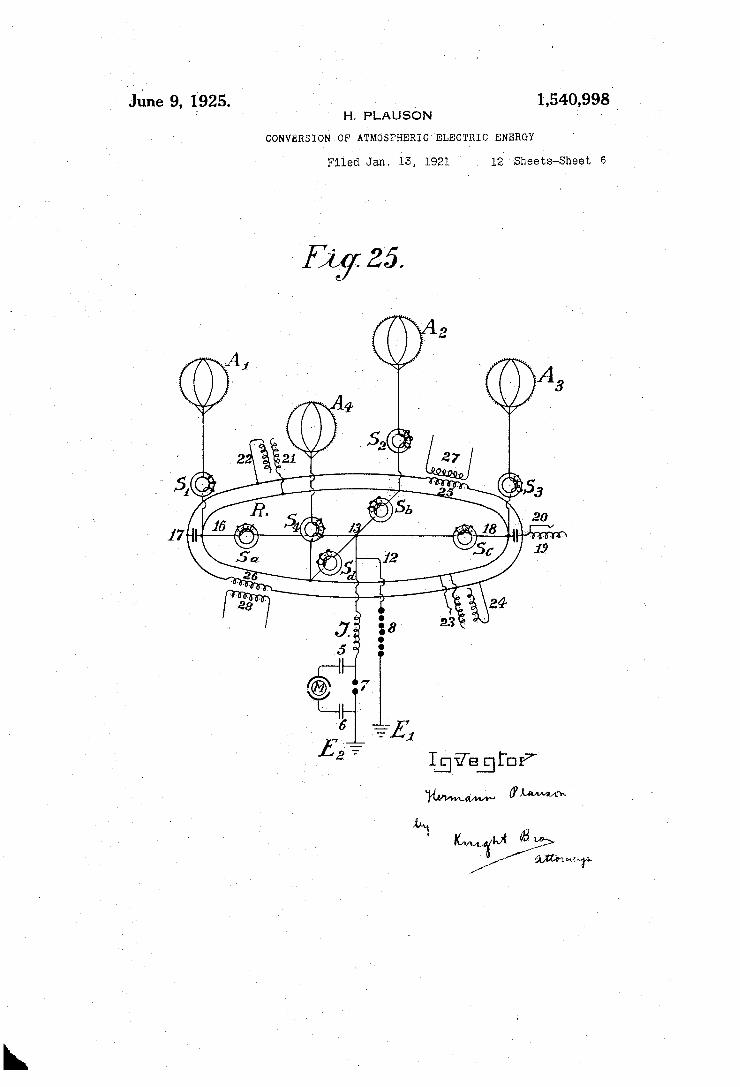
other free condenser pole, and if'thro‘ugh the ' spark ' gap a short circuit. results, 1 the ' accu mulated energy is again given back since ' now new‘ quantities of energy-are induced at the'condenser pole'oonnected with the conductor network, which in fact charges with opposite ‘signs to that at the'free "con denser pole.‘ The new. induced charges have of course the same sign asthe collectornet ,work. .The whole voltage energy in the aerial is thereby however increased.” In the " same space of time. larger quantities of; energy are accumulated ‘than is the case without such inserted condenser batteriesf " _'In.Figures 251 and 25 two_di?erent dia-r grams‘ of connections -' are more exactly illuse;
‘and the diagram of- the ccnnections‘to earth‘. Figure 25 four collecting balloons-and ‘the, parallel connection‘ of a. the condenser'baty teriesbelohging thereto. ~ -. A is ‘the collecting balloon’ inadeiof an‘
aluminium magnesium alloy (electron metal, ' inagnalium) of a speci?c gravity of 1.8‘and
a- thickness'of plate 0.1 to 0.2 mm. Inside there are. eight strong ‘vertical ribs of T shaped section about‘ 10 to 20min, in height and'about 3‘mm’.iinfthickness withj-j'the pro. jecting part directed‘inwa'rds (indicated by a, 7), '0, d and so forth): they are riveted to" géther to form a firm skeleton and are stiff-V“; ened in‘ a horizontal direction» byptwo cross ribs. Thejribs are ~further'connected with
"i one another intern'allyand transversclyhby
. external surface is obtained.
means of thin steel Wires, whereby the balé. . 'loon ohtainsgreat power of resistance and
‘elasticity. ‘ Rolled plates 010.1‘ to 0.2 mm. in - thickness made of magnaliurnp alloy are then‘
either solderedfor rivetedoh this skeleton so th'at‘a fully metallic casingwith smooth
\Vell silvered .o'r ‘copper-‘ed aluminium plated steel wires'run from each rib to the fastening ring 2. @Frir ther. the c’oppered steelhawser L preferably twisted out of, separate'thinwires .(shown in
- dotted linesin ‘Figure’ 24) and 'which riust ' ~ belong enough to allow theiballoon to rise
in the desired height, leadsptoa metal-roller on pulley 3 and from‘ thenceto a winch W, I
"l . well insulated from the ‘earth. . By means of this winch, the balloon, wh'ichis ?lled with " hydrogen, or ‘helium, can be allowed to rise to a suitable height (,300to' 5,000 metres) vand brought to the ground ‘for rechargii'ig" or repairs. > ' H . .
The actual current is taken- directly through a friction contact from the metal roller '3 or from the wire, or even from the '
' much or simultaneously .from all three by means of brushes (3, 5a and 3b). vBeyond the brushes the ‘conductor isv divided, the paths being :——'firstly'over 12 to the safety spark gap 8, from thence to th'e'earth con ductor E1, and secondly over elettromagnet S1, point 13, to a second loose electromagnet
; , 1,540,998
havingianladjustable coil S2, then to the‘ spark gap 7 and to‘ the, second earth con ductor E2; “The actual working-circuit is.. formed throughthe spark gap I7 , condensers" I 5 and '6, and through the primarv coil 9; here the static electricity lformed'iby oscil- latory discharges: is accu‘niulatedand con- . reried into high frequency electromagnetic
‘ - I I _ . .
OSCIlla-tIOIIS.‘ Between the electromagnets S1 < ‘and S2 ‘at the crossing point 13, four con-' denser batteries are introduced which» are only indicated diagrammatically .in the *drawin'gscach by one condenser, Two of f-these batteries. (16 and 18) are made as plate condensers and ‘prolonged by reigulatii'igxin hduction coils?or s'pirals'l? and 19 while‘ the
‘trated, Figure 24 shows; a collecting balloon‘ 't'woothers (2-1 and‘23) are induction con Y?(lense_rs._ As may'be seen from the drawings each of the‘four condenser batteries 16, l8,w .1215" ‘a ‘aerial-{or to; the vcollector conduct-or. ‘ The
Jisv connected‘only byone poleto the
70
second-poles ,17, 19, 22, ‘2-1 are open. In, the. 1,‘ case of‘ plate'condensers haying'noin‘ductive resistance an induction coil is lnserted; _-'l‘hc
Kobject of-s'uch a spiral or coil is the displace
periods, whilst‘ the charging current of the condenser‘ poles ‘which lie free in the, air,’
.v works back ,toilthe‘collectorv aerial. The con sequence of this'isthat-in discharges in the . collector aerialitheiback inductive action of their-cc polesallowsa higher voltage to be _ maintained in the aerial collecting c'on- - ,ductor thanwould'otherwise be the case’. It has also been, foundthat such a back action
wear of the contacts.
v9,0‘ mentof phaseof the induction‘ currentby 1,4
has an extremely, favourable effect, on the Of course the .induc- ‘
j tiveetfect may be regulated at will within
95
the limits of the ‘size ofthe induction coil, \ the length of the coil in action- being ad- ' 105 ‘ju'stable by meanso-f wire connection 'with- > ' ‘out induction (see Fig.‘ 24, No. 20)". '
S1 andiS2 mayialso be provided with such regulating 'devic‘esfin‘the case of S2 (illus
‘v-trated by 11)} v'Ir‘jfemess tvoltage be formed it is conducted to’earth through the wire 12 and spark'gapv 8 or-through any other suit able apparatus, since this formation would be dangerous for the other ‘apparatus. _ ' The action of these condenser batteries has
already been hereinbefore described. _ The small circles'on the collector balloon
indicate places at which zinc amalgamv or
110’
gold amalgam-or other photoelectric‘ acting ‘ metals in the form of small patches in €X-_ ‘ tremely thin layers (.01 to .05 min, in thickness) are applied to-the balloon’ casing of light rnetal. ‘Such metallic patches may ' also ‘be applied to the entire balloon aswell as in greater thickness to the conducting network. The capacity of the collector is thereby .co/nsiderably ' strengthened at the surface. The greatest possible eliect in col lectingv may be obtained by‘polonium amals gains and the like. ,On the surface of the 130
la in
8
collectorballoon metal points or spikes are, also fixed along the ribs, which spikes serve particularly for collecting the collector charge. Since it is well known that the re sistance of‘ the spikes isless the sharper the spike is, for this purpose it is therefore ex tremely important to .employ as sharp spikes as possible. Experiments made .as regards. these hayeshown that the forma tion of the body of the spike or point also plays a large part. for example, spikesmade of bars or rollers with smooth surfaces, have a many times greater point resistance as collector accumulator spikes than those with rough surfaces. Various kinds of spike bodies have, been experimented with for the collector balloons hereinbefore men tioned. The best results were given by spikes which were made in the following way. Fine points made of steel, copper, nickel, or copper and nickel alloys, were fas tened together in bundles and then placed as anode with the points in a suitable elec trolyte (preferably in hydrochloric acid or muriate'of iron solutions) and so treated with weak current at 2 to 3 voltspressure.‘ After 2 to 3 hours according to the thick ness of the‘spikes orpins the points become extremely sharp and the bodies of the spikes have a rough surface. The bundle can then be removed and the acid washed off with water. The spikes are thenv placed as cathode in a bath consisting of solution of gold, platinum, iridium, paladiumcr wolf ram salts or their compounds and coated at the cathode galvanically‘ with a. thin layer
' of precious metal, which‘ must however be
4 O
60
65
sufficiently firm to protect. them from at mospheric oxidation. _ Such spikes act at a 20 fold lower voltage
almost as well as the bestand ?nest points made by mechanical means. Stillbetter re— sults are obtained if‘ polonium or radium salts are added to the galvanic bath when' forming the protective layer or coating. Such pins have a low resistance at their points and even at one Volt. and still lower’ pressures have an excellent collector action.
In Figure 24 the three unconnected poles are not connected with‘one another in par-_
That 15 quite possible ID'PI‘JCUCO' allel. without altering the principle of the free pole: It is also preferable to interconnect in parallel to a common collector network, a series of collecting aerials. Figure 25 shows a diagram for such an
installation. A1. A2, A3, A;4 are fourmctal collector balloons with -gold ,or platinum coated spikes which are electrolytically made in‘ the presence of polonium emana tions or radium salts, which spikes or nec dlcs are connected over four electro-magnets S1, S2, S3, i. 4. through an annular conductor R. From this annular conductor four wires run over four further electromagnets S“,
1,540,998
S", U9, S“, to the connecting point 13. There vthe conductor is divided, one. branch passing over 12 and the safety spark gap 8 to the earth at E1, the other over inductive resist ance J and workingr spark gap 7 to the earth at E2. The working circuit, consisting of the condenser 5 and (3 and a resonance motor or a condenser motor M, such as here inbefore described, is connected in prox imity' round the sparking gap section 7 .
Instead of directly connecting the con denser motor of course the primary circuit for high frequency oscillatory current'may also be inserted. _ . <
The condenser batteries are connected by one pole to the annular conductor R and can be either inductionless (16 and 18) or made as induction condensers as shown by 21 and 23. The free poles of the inductionless condensers are indicated by 17 and 19, those of the induction condensers by 22 and 24. As may be seen from the drawings all these ' poles 17. 22. 19, Qt‘may be interconnected .in parallel through. a, second annular con ductor without any fear that thereby the principle of the free pole connection will be injured. ,
already set forth the parallel connection also allows of an equalization of the work-_ ing pressure in the entire collector network. Suitably constructed and calculated induc~ tion coils 25 and 26 may also be inserted in the annular conductor of the free poles, by means of which a circuit may be formed in the secondary coils 27 and 28 which al lows current produced in this annular con ductor by ?uctuations of the charges or the ‘like appearances to be measured or other wise utilized. According to what has been hereinbefore
stated separate collector balloons may be connected at equidistant stations distributed over the entire country, either connected di rectly with one another metallically or by ‘means of intermediate suitably connected condenser batteries through vhigh voltage conductors insulated from earth._ The static electricity is converted through a spark gap into dynamic energy of :fhigh nuinber of'oscillations and may in such form be coupled as a source of energy by means of a‘suitable methodof connecting, various precautions being observed and with spc‘ cial regulations. The wires leading from .the collector balloons have hitherto been connected through an annular conductor without this endless connection, which can be regarded as an endless induction coil, be ing able to exert any action on the whole conductor system.
. It has now been found that if the network conductor connecting the aerial collector bal
lloons with one another is not made as a simpleannular conductor, but preferably short circuited 1n the form of coils ‘over a
In addition to the advantages.
80
100
110
115