Conversion Manual Between GIS and CORMAS - Ciradcormas.cirad.fr/pdf/GIS_Cormas.pdf · Conversion...
67
Conversion Manual Between GIS and CORMAS This manual was assembled by Arnel Rala (IRRI, Philippines) and François Bousquet (IRRI-Cirad, Thailand). This is a compilation of programs and documentations produced by Arnel B. Rala (IRRI, Philippines), Panomsak Promburom (University of Chiang Mai, Thailand), Michel Etienne (Inra, France), Tran Ngoc Trung (IRRI-Ird, Vietnam), Christophe Le Page and Pierre Bommel (Cirad, France). Any corrections-comment on this manual, or proposal of other methods will be appreciated.
Transcript of Conversion Manual Between GIS and CORMAS - Ciradcormas.cirad.fr/pdf/GIS_Cormas.pdf · Conversion...

CCoonnvveerrssiioonn MMaannuuaall BBeettwweeeenn GGIISS aanndd CCOORRMMAASS
This manual was assembled by Arnel Rala (IRRI, Philippines) and François Bousquet (IRRI-Cirad, Thailand).
This is a compilation of programs and documentations produced by Arnel B. Rala (IRRI, Philippines), Panomsak Promburom (University of Chiang Mai, Thailand), Michel Etienne (Inra, France), Tran Ngoc Trung (IRRI-Ird, Vietnam), Christophe Le Page and Pierre Bommel (Cirad, France). Any corrections-comment on this manual, or proposal of other methods will be appreciated.

TTAABBLLEE OOFF CCOONNTTEENNTTSS Conversion Manual Between GIS and CORMAS.........................................................1
Table of Contents...........................................................................................................2
1. Exporting Raster Data from GIS................................................................................5
1.1 Arcview....................................................................................................................5
Overview....................................................................................................................5
Objective ....................................................................................................................6
Expected Output.........................................................................................................6
Requirements .............................................................................................................6
Procedure ...................................................................................................................7
Configure Arcview’s environment ........................................................................7
Rasterization and Conversion to CORMAS ..........................................................9
Verification ..............................................................................................................12
1.2 IDRISI for Windows (16 bit version) ....................................................................13
Overview..................................................................................................................13
Objective ..................................................................................................................14
Expected Output.......................................................................................................14
Requirements ...........................................................................................................14
Procedure .................................................................................................................14
Verification ..............................................................................................................15
1.3 IDRISI 32.X (32 bits version)................................................................................16
Overview..................................................................................................................16
Objective ..................................................................................................................17
Expected Output.......................................................................................................17
Requirements ...........................................................................................................17
Procedure .................................................................................................................17
Configure IDRISI 32 working environment ........................................................17
Rasterization and Conversion ..............................................................................17
1.4 MAPINFO..............................................................................................................26
Overview..................................................................................................................26
Objective ..................................................................................................................27
Expected Output.......................................................................................................27
Requirements ...........................................................................................................27
Procedure .................................................................................................................27
2

Configure MapInfo Working Environment .........................................................27
Rasterization and Conversion ..............................................................................27
2. Importing ASC and ENV files to CORMAS...........................................................34
Overview..................................................................................................................34
Objective ..................................................................................................................34
Requirements ...........................................................................................................34
Expected Output.......................................................................................................34
Procedure .................................................................................................................34
Design a simple MAS model ...............................................................................34
Loading an ENV file ............................................................................................35
Loading ASC files................................................................................................36
3. Exporting Vector Data from GIS.............................................................................39
3.1 Arcview..................................................................................................................39
Overview..................................................................................................................39
Objective ..................................................................................................................40
Expected output .......................................................................................................40
Requirements ...........................................................................................................40
Procedure .................................................................................................................40
Configure Arcview’s environment ......................................................................40
Add a Theme to the View ....................................................................................41
Load the shp2mif script .......................................................................................41
3.2 IDRISI 32...............................................................................................................44
Overview..................................................................................................................44
Objective ..................................................................................................................45
Expected output .......................................................................................................45
Requirements ...........................................................................................................45
Procedure .................................................................................................................45
Configure IDRISI 32 working environment ........................................................45
Export the Vector file...........................................................................................45
3.3 Mapinfo..................................................................................................................47
Overview..................................................................................................................47
Expected output .......................................................................................................48
Requirements ...........................................................................................................48
Procedure .................................................................................................................48
Load a Table file ..................................................................................................48
3

4 Cormas : Importing Vectors.....................................................................................50
Overview..................................................................................................................50
Objective ..................................................................................................................50
Requirements ...........................................................................................................50
Expected Output.......................................................................................................50
Procedure .................................................................................................................50
5 Cormas : exporting ASC files ...................................................................................53
Objective ..................................................................................................................53
Requirements ...........................................................................................................53
Expected Output.......................................................................................................53
5.1 ArcView.................................................................................................................53
Cormas to ASC files ............................................................................................53
Importing in ArcView..........................................................................................54
5.2 Idrisi 32 bits ...........................................................................................................58
Exporting Cormas data ............................................................................................58
Importing in Idrisi ....................................................................................................60
Note : Idrisi 16 bits ..................................................................................................63
5.3 MAPINFO..............................................................................................................63
6. Exporting MIF MID data from Cormas...................................................................64
Objective ..................................................................................................................64
Requirements ...........................................................................................................64
Expected Output.......................................................................................................64
Procedure .................................................................................................................64
4

11.. EEXXPPOORRTTIINNGG RRAASSTTEERR DDAATTAA FFRROOMM GGIISS Most of the Multi-Agent Systems developed with Cormas use a spatial environment which is similar to cellular automata. Thus the most “natural” format to exchange data with GIS is the Raster mode.
SOURCESOURCE
CORMASCORMAS
ASC Files ENV Files
ARCVIEWARCVIEW IDRISI 32IDRISI 32 MAPINFOMAPINFO
IMG File
IDRARCIDRARC
SHP File
GRD File
ASC File
RST File
SHP File
Convert to Grid
RST File
VCT File
Convert to VCT
RST Text File
Edit to include header
TAB File
MIF/MID File
GRD File
TAB File
Import
GriddedTAB File
Make Grid
TXT File
Recode column ID, sort andinclude header
Assign Values
Export to TXT fileExport to ASCII Raster
Export to ASCII Raster
RST File
Convert to RST
Convert to ASCII Format
Rasterize
Assign User Codes
Figure 1. Flow diagram of the conversion process from a Raster GIS data to Cormas.
1.1 Arcview Overview Arcview’s native data format is vector based commonly referred to as Shape Files. Shape files are composed, at a minimum, of three data file namely the SHP, SHX, and DBF. The SHP file contains all the graphical representation of the theme or layer, while the DBF file holds all the attribute data. The SHX file serves as an index that binds the two previous files together. The extension, Spatial Analyst, enables ArcView to work with raster based data such as ESRI’s grid files and other image files. Arcview also include the
The article ‘Introduction to Arcview ‘by Ron Briggs provides detail information about ArcView and ArcViewdata sourc
’s es.
5

functionality to import data from other GIS and non-GIS softwares, but we will not deal with this.
We will be focussing our work on the conversion of Shape and Grid files to a data format that CORMAS can work on. Figure 2 illustrates the process which we will go about in this exercise.
Figure 2 Conversion process of GIS data to CORMAS using ARCVIEW
Path 2 Path 1
Convert to Grid
Export as ASCII
Grid file
Shape file
ArcView
Grid file Shape file
ASCIIGRIDFILE
CORMAS
Objective 1. To be familiar with ArcView’s environment
2. To convert Arcview’s Shape and Grid file data to a format which CORMAS can use
Expected Output ASCII Grid File
Requirements 1. ArcView GIS
2. Spatial Analyst
3. Shape file (ph_thanh_soil)
4. Grid file (soilgrid)
6

5. A working knowledge about the basics of ArcView
Procedure There are two path in the process to consider depending on the data source. Converting Grid file to CORMAS is the shortest and easiest as it involves only one step compared to Shape file.
Configure Arcview’s environment
1. Open Arcview. By default, a New Project named ‘Untitled’ with a blank View named ‘View1’ is created. Otherwise, click on the New button in the Project Window to create a new View.
2. Define the properties for View1.
a) On the Menu bar, choose on View/Properties to access the View Properties Box.
b) Set the appropriate Map Unit (e.g., decimal degrees or meter) that would correspond to the theme’s unit of measure (this is dependent on the theme’s projection). All other input can be left as is. Choose OK
7

3. Load the Spatial Analyst extension.
a) On the Menu bar, choose on File/Extensions to access the Extensions Box.
b) Click on the Check box beside ‘Spatial Analyst’ (if there is no check mark)
c) Choose OK
4. Configure the Spatial Analyst’s Analysis environment.
a) On the Menu bar, choose on Analysis/Properties to access the Analysis Box.
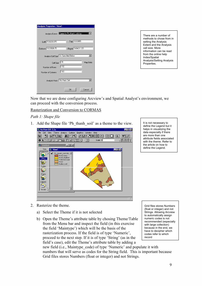
b) Set the Analysis Extent similar to the theme’s extent (i.e., Same as Ph_thanh_soil.shp). This method will extract coordinate values from the theme and place it in the left, top, bottom, and right input boxes.
c) Set the Analysis Cell Size method to ‘As Specified Below’. This method will allow you to manually key-in a predetermined cell resolution in the Cell Size input box (Number of Rows and Number of Columns will be computed automatically and reflected in the input boxes after you clicked OK).
d) Click OK
8
Now that we are done configuring Arcview’s and Spatial Analyst’s environment, we can proceed with the conversion process.
Rasterization and Conversion to CORMAS
Path 1: Shape file
1. Add the Shape file ‘Ph_thanh_soil’ as a theme to the view.
2. Rasterize the theme.
a) Select the Theme if it is not selected
b) Open the Theme’s attribute table by chosing Theme/Table from the Menu bar and inspect the field (in this exercise the field ‘Maintype’) which will be the basis of the rasterization process. If the field is of type ‘Numeric’, proceed to the next step. If it is of type ‘String’ (as in the field’s case), edit the Theme’s attribute table by adding a new field (i.e., Maintype_code) of type ‘Numeric’ and populanumbers that will serve as codes for the String field. This is iGrid files stores Numbers (float or integer) and not Strings.
It is not necessary to define the Legend but it helps in visualizing the data especially if there are more than one attribute fields associated with the theme. Refer to the article on how to define the Legend.
There are a number of methods to chose from in setting the Analysis Extent and the Analysis cell size. More information can be reafrom the online help Index/Spatial
d
Analysis/Setting Analysis Properties.
Grid files stores Numbers (float or integer) and not Strings. Allowing Arcview to automatically assign numeric codes is not recommended (especially with large collection) because in the end, we have to decipher which codes refer to which record
te it with mportant because
9

c) On the Menu bar, choose Theme/Convert To Grid. This will invoke the Convert box where you specify the output filename and the path to store the output. Bear in mind that the filename must not exceed eight characters. Choose OK.
d) The Conversion Field box will open and select the field to where the cell
values of your output will be based upon (i.e., Maintype_Code). Choose OK and Arcview will start the rasterization process.
e) The Attribute Join box will open when the rasterization
process has finished. It inquires whether to join the attribute data of the theme to your newly created Grid file. A’No’ will suffice for this exercise.
Joining the attribute table to the output Grid file is ideal if you will do on-screen querying with the identify tool
f) Lastly, the Convert to Grid box will open inquiring to add the Grid file as a
new Theme in the View. Choose ‘Yes’
Adding the Grid file to the View will aid in validating the rasterization process
10
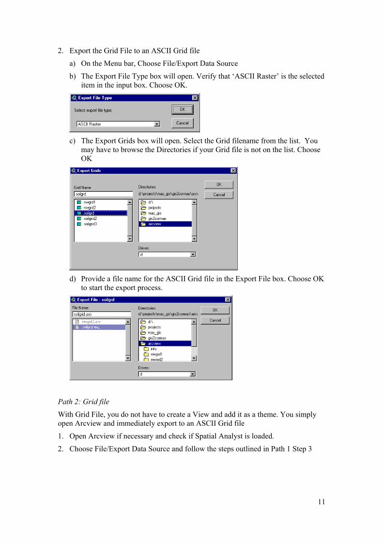
2. Export the Grid File to an ASCII Grid file
a) On the Menu bar, Choose File/Export Data Source
b) The Export File Type box will open. Verify that ‘ASCII Raster’ is the selected item in the input box. Choose OK.
c) The Export Grids box will open. Select the Grid filename from the list. You
may have to browse the Directories if your Grid file is not on the list. Choose OK
d) Provide a file name for the ASCII Grid file in the Export File box. Choose OK
to start the export process.
Path 2: Grid file
With Grid File, you do not have to create a View and add it as a theme. You simply open Arcview and immediately export to an ASCII Grid file
1. Open Arcview if necessary and check if Spatial Analyst is loaded.
2. Choose File/Export Data Source and follow the steps outlined in Path 1 Step 3
11

Verification 1. Open any word processor (e.g., wordpad) and load the ASCII Grid file,
‘soilgrid.asc’.
2. The file should look something like the figure below. It is vital to remember the Column (ncols) and Row (nrows) values because this will be used to define the grid environment in CORMAS.
12
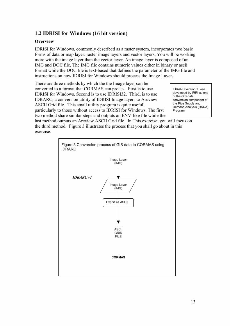
1.2 IDRISI for Windows (16 bit version) Overview IDRISI for Windows, commonly described as a raster system, incorporates two basic forms of data or map layer: raster image layers and vector layers. You will be working more with the image layer than the vector layer. An image layer is composed of an IMG and DOC file. The IMG file contains numeric values either in binary or ascii format while the DOC file is text-based that defines the parameter of the IMG file and instructions on how IDRISI for Windows should process the Image Layer.
There are three methods by which the the Image layer can be converted to a format that CORMAS can proces. First is to use IDRISI for Windows. Second is to use IDRISI32. Third, is to use IDRARC, a conversion utility of IDRISI Image layers to Arcview ASCII Grid file. This small utility program is quite usefull particularly to those without access to IDRISI for Windows. The first two method share similar steps and outputs an ENV-like file while the last method outputs an Arcview ASCII Grid file. In This exercise, you will focus on the third method. Figure 3 illustrates the process that you shall go about in this exercise.
IDRARC version 1 was developed by IRRI as one of the GIS data conversion component of the Rice Supply and Demand Analysis (RSDA) Program
Image Layer (IMG)
Export as ASCII
ASCIIGRIDFILE
CORMAS
IDRARC v1
Figure 3 Conversion process of GIS data to CORMAS using IDRARC
Image Layer (IMG)
13
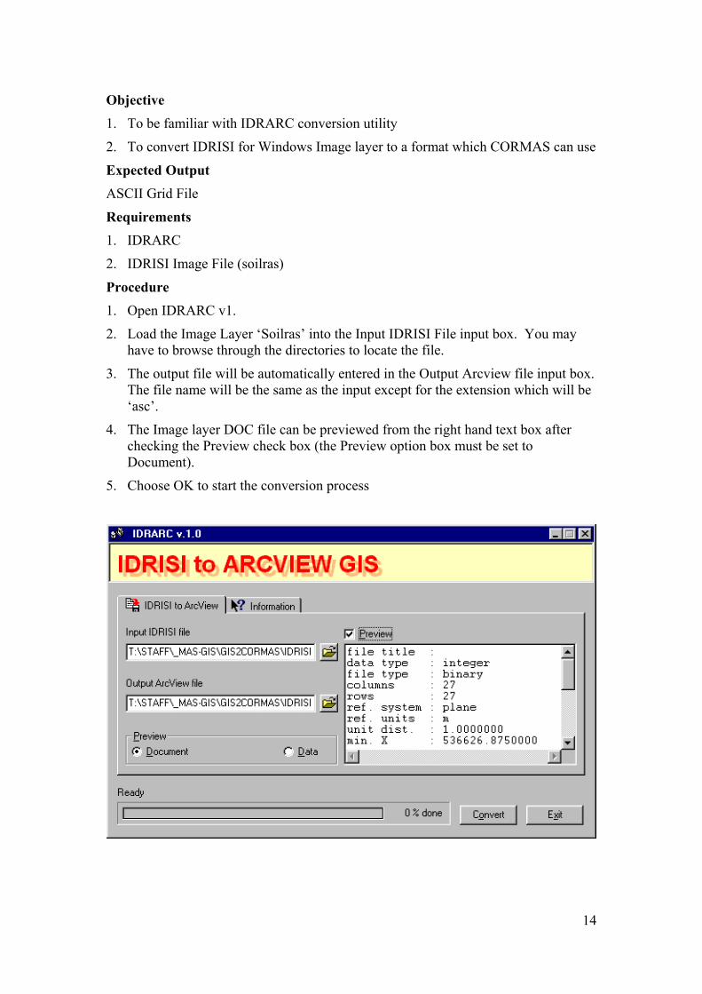
Objective 1. To be familiar with IDRARC conversion utility
2. To convert IDRISI for Windows Image layer to a format which CORMAS can use
Expected Output ASCII Grid File
Requirements 1. IDRARC
2. IDRISI Image File (soilras)
Procedure 1. Open IDRARC v1.
2. Load the Image Layer ‘Soilras’ into the Input IDRISI File input box. You may have to browse through the directories to locate the file.
3. The output file will be automatically entered in the Output Arcview file input box. The file name will be the same as the input except for the extension which will be ‘asc’.
4. The Image layer DOC file can be previewed from the right hand text box after checking the Preview check box (the Preview option box must be set to Document).
5. Choose OK to start the conversion process
14
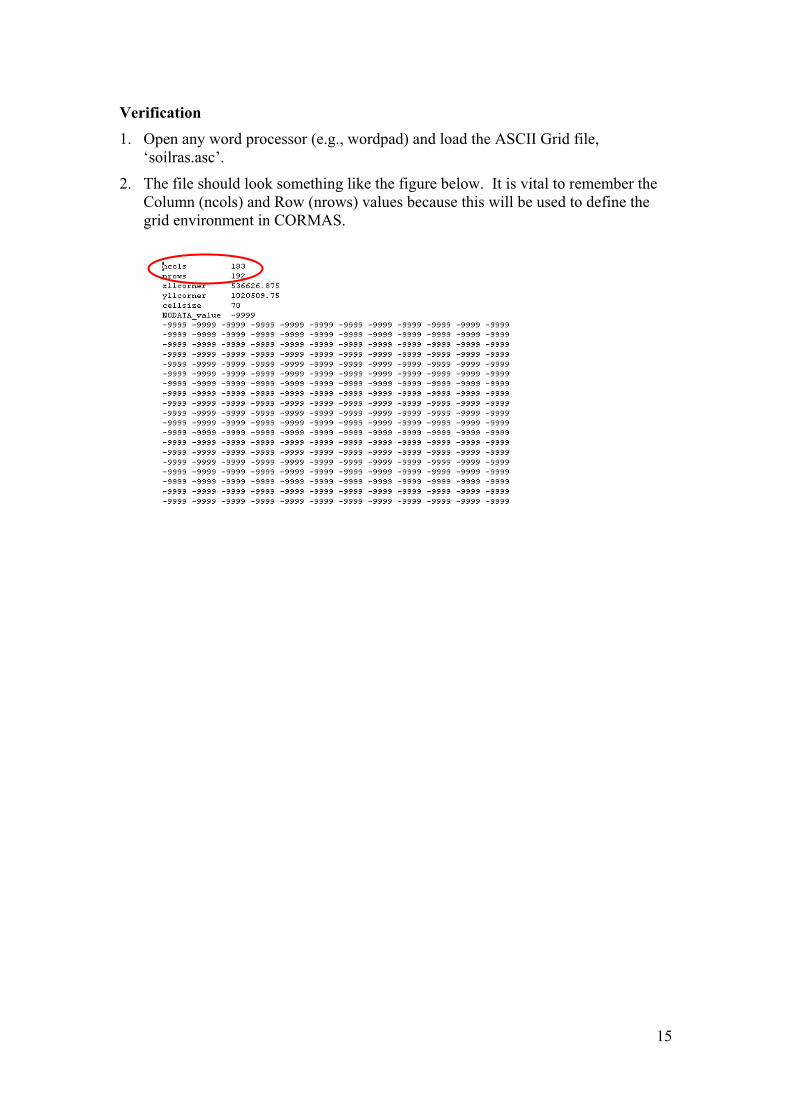
Verification 1. Open any word processor (e.g., wordpad) and load the ASCII Grid file,
‘soilras.asc’.
2. The file should look something like the figure below. It is vital to remember the Column (ncols) and Row (nrows) values because this will be used to define the grid environment in CORMAS.
15
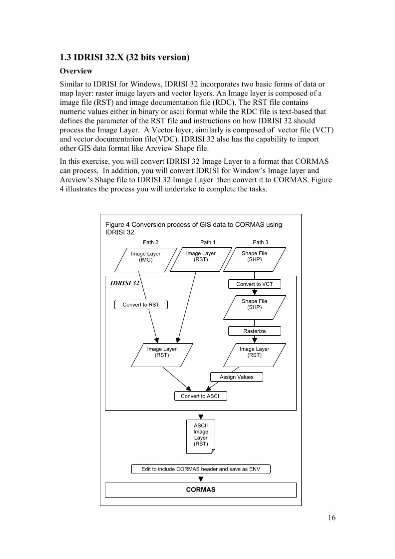
1.3 IDRISI 32.X (32 bits version) Overview Similar to IDRISI for Windows, IDRISI 32 incorporates two basic forms of data or map layer: raster image layers and vector layers. An Image layer is composed of a image file (RST) and image documentation file (RDC). The RST file contains numeric values either in binary or ascii format while the RDC file is text-based that defines the parameter of the RST file and instructions on how IDRISI 32 should process the Image Layer. A Vector layer, similarly is composed of vector file (VCT) and vector documentation file(VDC). IDRISI 32 also has the capability to import other GIS data format like Arcview Shape file.
In this exercise, you will convert IDRISI 32 Image Layer to a format that CORMAS can process. In addition, you will convert IDRISI for Window’s Image layer and Arcview’s Shape file to IDRISI 32 Image Layer then convert it to CORMAS. Figure 4 illustrates the process you will undertake to complete the tasks.
Path 3 Path 1 Path 2
Convert to VCT
Rasterize
Shape File (SHP) Convert to RST
Assign Values
Edit to include CORMAS header and save as ENV
Convert to ASCII
Image Layer (RST)
Image Layer (RST)
ASCII Image Layer (RST)
CORMAS
IDRISI 32
Shape File (SHP)
Image Layer (RST)
Image Layer (IMG)
Figure 4 Conversion process of GIS data to CORMAS using IDRISI 32
16

Objective 1. To be familiar with IDRISI 32 environment
2. To convert IDRISI 32 Image layer to a format which CORMAS can use
3. To import and convert other GIS data format like IDRISI for Windows’s Image Layer and Arcview’s Shape file within IDRISI 32.
Expected Output
1. ASCII Image Layer (RST)
2. ENV File
Requirements 1. IDRISI 32
2. IDRISI Image File (soilras-16bit and soilras-32bit)
3. Arcview Shape File (ph_thanh_soil)
4. A working knowledge about the basics of IDRISI would be a plus
Procedure There are three path in the process to consider depending on the data source. Converting IDRISI 32 Image Layers (RST) to CORMAS is the shortest and easiest as it involves only one step.
Configure IDRISI 32 working environment
1. Open IDRISI 32.
2. Choose ‘File/Data Paths’ from the Menu bar and the Project Environment box will open.
3. Set your Main Working folder by browsing through the directory where your data files are stored if necessary
Rasterization and Conversion
Path 1: Image Layer (RST) of IDRISI 32 1. Visualize the Image
a) Choose ‘File/Display/Display Launcher from the menu bar
b) Set ‘File Type To Be Displayed’ to Raster Layer, ‘Palatte File’ to user defined and browse for NDVI 16
c) Browse the directory for the Image Layer and select the filename to be displayed (e.g., soilraster)
d) Choose OK and the Raster layer will be drawn on the display window
17

2. Convert to ASCII Raster Layer
a) Choose ‘Reformat/Convert’ from the Menu bar to open the Convert box.
b) Choose Image as the File Type
c) Provide the Input File Name (e.g., soilras) and the Output File Name (e.g., soilrasterasccii)
d) Choose Integer as the Output Data Type and ASCII as the Output File Type
e) Choose OK to start the conversion process
18

3. Modify RST file to ENV file
There will be 2 output files after step 1. The RST is in ascii format with one column of data while the RDC, also in ascii format, describes the parameters of the RST file.
a) Open the RST file using notepad or any word processor.
b) Include the following as the first 5 lines. Your file should look like the figure below
c) Save the file in ascii/text format with a new extension, ENV. This file can
now be imported by CORMAS
Path 2: Image Layer (IMG) of IDRISI for Windows
1. Import Image Layer (IMG)
a) Choose ‘File/IDRISI Conversion Tool’ from the menu bar
b) Verify the settings are similar to the figure above.
19

c) Provide the filename for the Input Raster Image (e.g., soilras). By default the Output Raster Image will be of the same filename. It is best to change the output filename to avoid confusion (i.e., soilras32)
d) Choose OK to start the conversion process
2. Visualize the Image
Follow the steps outlined in Path 1 Step 1
3. Convert to ASCII Raster Layer
Follow the steps outlined in Path 1 Step 2
4. Modify RST file to ENV file
Follow the steps outlined in Path 1 Step 3
Path 3: Shape file of ArcView
1. Import Shape file to IDRISI Vector file
a) Choose ‘File/Impot/Software Specific Format/ShapeIDR from the menu bar
b) Specify Input Shapefile (e.g., ph_thanh_soil.shp), Output IDRISI vector file
(e.g., soilVector.vct). Optionally fill in the Reference system, Reference units, Unit distance and Title.
c) Choose OK. A VCT and VDC files are created after the process . Similar to the Shape file, your Vector file contains polygon features.
2. Visualize the Vector file
Follow the steps outlined in Path 1 Step 1 but instead of Raster Layer, set ‘File Type To Be Displayed’ to Vector Layer
20
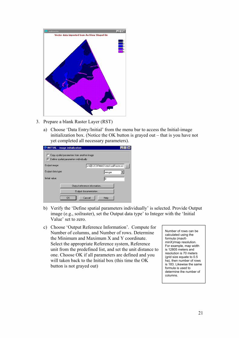
3. Prepare a blank Raster Layer (RST)
a) Choose ‘Data Entry/Initial’ from the menu bar to access the Initial-image initialization box. (Notice the OK button is grayed out – that is you have not yet completed all necessary parameters).
b) Verify the ‘Define spatial parameters individually’ is selected. Provide Output
image (e.g., soilraster), set the Output data type’ to Integer with the ‘Initial Value’ set to zero.
c) Choose ‘Output Reference Information’. Compute for Number of columns, and Number of rows. Determine the Minimum and Maximum X and Y coordinate. Select the appropriate Reference system, Reference unit from the predefined list, and set the unit distance to one. Choose OK if all parameters are defined and you will taken back to the Initial box (this time the OK button is not grayed out)
Number of rows can be calculated using the formula (maxX-minX)/map resolution. For example, map wiis 12805 meters and resolution is 70 mete(grid size equate to 0.5 ha), then number of rowis 183. Likewise theformula is used to determine the number of columns.
dth
rs
s same
21

d) Choose OK
4. Rasterize the Vector file (Update Raster Layer created from Step 5)
a) Choose ‘Reformat/RasterVector Conversion/Polyras’ from the menu bar. Provide the Vector Polygon File (e.g., soil vector) and the Image file to be updated (e.g.,soilraster). Choose OK.
If you did not prepare a blank Raster Layer an error message will appear warning you that the image to be updated do not exists. It also ask to create the image using the INITIAL module. Choose YES and follow Step 5
b) The result of raster image will be displayed on screen. Note that the cell values
are generated automatically by IDRISI 32. This is referred to as the internal code (IDR_ID) that serve as the primary key to link the cells to the attribute database of the Vector Layer.
22
5. Create the Values File
a) Choose ‘Data Entry/Database Workshop’ from the menu bar to access the Database Workshop box. The Database workshop allows you to manipulate the attribute database of a Vector file and other databases.
b) Choose File/Open from the menu bar of the Database Workshop box to access the Open Database Box. Provide the Database Name (e.g. soilvector) and select the Table Name from the dropdown list (if there are more than one tables in the database, in this case there is only one). The Table should look like this.
c) Export the fields to a Values File. Choose ‘File/Export Values (avl) File’ from
the Menu bar of the Database Workshop. This option creates a 2-column space-delimited ASCII attribute values (avl) file from two database fields. After providing a name for the file, indicate the Link field (e.g., IDR_ID) and
23

the Data field (e.g., SoilID), which will form the first and second columns respectively. Note that Raster Layers accommodate numeric values only.
d) Close the Database Workshop
6. Assign attribute values of the Vector Layer to the Raster Layer.
a) Choose ‘Data Entry/Assign’ from the Menu bar to access the Assign – attribute values assignment box.
b) Supply the need parameters and Choose OK. The resulting raster file will
have values that properly characterizes the polygon. Other attribute fields can be linked to the raster file resulting in a number of unique raster file. Again, it is important that the fields to be linked are of type numeric (i.e., text or string fields can not be exported as value files).
24

7. Convert to ASCII Raster Layer
Follow the steps outlined in Path 1 Step 2
8. Modify RST file to ENV file
Follow the steps outlined in Path 1 Step 3
25
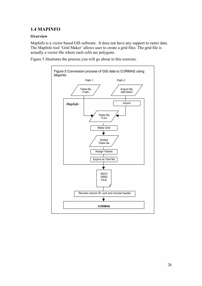
1.4 MAPINFO Overview MapInfo is a vector based GIS software. It does not have any support to raster data. The MapInfo tool ‘Grid Maker’ allows user to create a grid files. The grid file is actually a vector file where each cells are polygons.
Figure 5 illustrates the process you will go about in this exercise.
Figure 5 Conversion process of GIS data to CORMAS using MapInfo
Recode column ID, sort and include header
Assign Values
Export as Text file
Make Grid
Import
Path 2 Path 1
Grided Table file
Table file (Tab)
MapInfo
Export file(MIF/MID)
Table file (TAB)
ASCIIGRIDFILE
CORMAS
26

Objective 1. To be familiar with MapInfo environment
2. To convert Table files and Export files to a format which CORMAS can use
Expected Output ENV File
Requirements 1. MapInfo
2. MapInfo Table File
3. MapInfo Export File
Procedure Configure MapInfo Working Environment
1. Open MapInfo
2. Load the Grid Maker
a) Choose ‘Tools/Tool Manager’ to access the Tool Manager box. Check the boxes opposite the Grid Maker tool representing loaded and Autoload
b) Choose OK
Rasterization and Conversion
Path 1: Table Files (TAB)
1. Load the Table file
a) Open MapInfo
b) Select ‘File/Open Table’ from the menu bar to access the ‘Open Table’ window and select the table name to load (soilTab.tab). A ‘Map’ window will open containing the map representation of the table
27

2. Set the map projection.
a) Choose ‘Map/Option’ to acesss the ‘Map Option’ window and click on the ‘Projection’ button to access the ‘Choose Projection‘ window
b) If the projection is non-earth, change the ‘Category’ and select ‘category
Members’
28
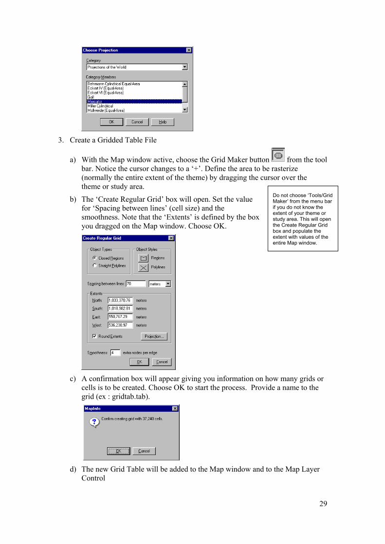
3. Create a Gridded Table File
a) With the Map window active, choose the Grid Maker button from the tool bar. Notice the cursor changes to a ‘+’. Define the area to be rasterize (normally the entire extent of the theme) by dragging the cursor over the theme or study area.
Do not choose ‘Tools/Grid Maker’ from the menu bar if you do not know the extent of your theme or study area. This will open the Create Regular Grid box and populate the extent with values of the entire Map window.
b) The ‘Create Regular Grid’ box will open. Set the value for ‘Spacing between lines’ (cell size) and the smoothness. Note that the ‘Extents’ is defined by the box you dragged on the Map window. Choose OK.
c) A confirmation box will appear giving you information on how many grids or
cells is to be created. Choose OK to start the process. Provide a name to the grid (ex : gridtab.tab).
d) The new Grid Table will be added to the Map window and to the Map Layer
Control
29

4. Update Grid Table File with values from Table File.
a) Choose ‘Map/Layer Control’ from the menu bar and allow editing of the grid tab layer by checking the checkbox under the Pen column. Choose OK.
b) Choose Table/Update Column from the menu bar. Browse through the list and
set the fields ‘Table to Update’, ‘Column to Update’, ‘Get Value From Table’, ‘Calculate’, and ‘Of’ to gridtab, add new temporary column, soil, value, and maintype, respectively.
The join method is dependent on the cell size of the Grid Table compared to the smallest polygon of the vector map. If it is smaller then choose ‘where object from the table contains object from the table’ If it is larger then choose ‘where object from the table is within object from the table’If it is similar then test the solution (a) or take ‘where object from the table intersects object from the table’
c) Click the Join button to specify the join method. Select the second option and choose intersects from the list. Choose OK
d) Choose OK to start the update process. Repeat the above steps as may times as
you need variables to be imported in Cormas.
e) Save the Grid Table using ‘Save as’.
30

5. Export to a delimited ascii file.
a) Choose ‘Table/Export’ to save the Grid Table as a text file
b) It is recommended to use the ‘tab’ as a separator because in some cases the a
variable may contain a comma as part of the record.
6. Modification to the text file
The resulting MapInfo file is stored column by column (from the top left to the bottom left first). However, Cormas imports data stored by line (from the top left to the top right first). So data has to be sorted.
MapInfo proposes some utilities to sort the column but there is a problem for sorting. The columns are labeled by letters, A, B, C. If the number of columns exceed 27 then Mapinfo uses AA, AB, etc. When sorted the order is A, AA, B… instead of A, B, … Z, AA.
If anyone has a solution, please email the cormas list.
Thus we have chosen to use Excel to sort the data.
a) Open the file
31

b) Search and replace any comma by a blank character ( see « Acid, deep »
above).
c) Create a new column (Col for instance) and assign values from 1 for the first data row and then increment (for instance use the function ‘=line(e1)’ and copy to the bottom) .
d) You can also delete the two first columns.
e) Sort the the table by Row then by Column.
f) Saved the file as a csv file ( ascii delimited by ‘;’).
g) Change the extension .csv by an extension .env . Open the file with Wordpad, search and replace all ‘;’ by ‘,’ and add the lines at the top.
32
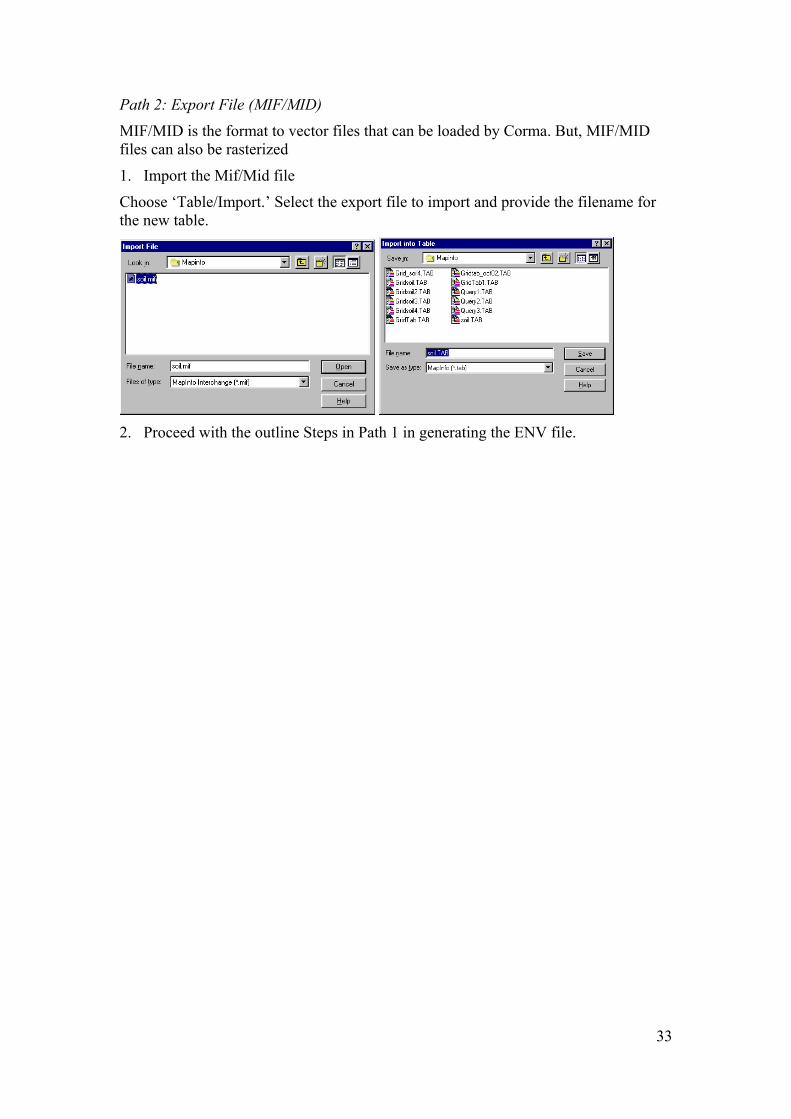
Path 2: Export File (MIF/MID)
MIF/MID is the format to vector files that can be loaded by Corma. But, MIF/MID files can also be rasterized
1. Import the Mif/Mid file
Choose ‘Table/Import.’ Select the export file to import and provide the filename for the new table.
2. Proceed with the outline Steps in Path 1 in generating the ENV file.
33

22.. IIMMPPOORRTTIINNGG AASSCC AANNDD EENNVV FFIILLEESS TTOO CCOORRMMAASS Overview Cormas is an object oriented software. There are various spatial entities but there is only one “Cell” which the smallest spatial entity. If the tessellation of Cormas is regular, Cormas will load ASC and ENV files on the Cells. Each cell must have a specific attribute for each layer. Consequently, for one cell, the values of the different layers are loaded in the same object.
Objective 1. To be able to load ASC and ENV files exported from different GIS software
Requirements
1. Visual Works
2. CORMAS
3. ASC and ENV files
4. A working knowledge in CORMAS Modeling
Expected Output
Cormas model with the ASC and ENV files as environment
Procedure
Design a simple MAS model
1. Initialize CORMAS
a) Open Visual Works and choose ‘Tools/CORMAS/Cormas English’. The Cormas Modeling interface will appear
b) Choose ‘Model/New’ and provide a name for the model
2. Define the Spatial Entity
a) Right mouse click on the Spatial box and choose ‘Add/Elementary Spatial Entity/Cell’. This cell need to have at least as many attributes as variables to be loaded from the ENV or ASC files.
34
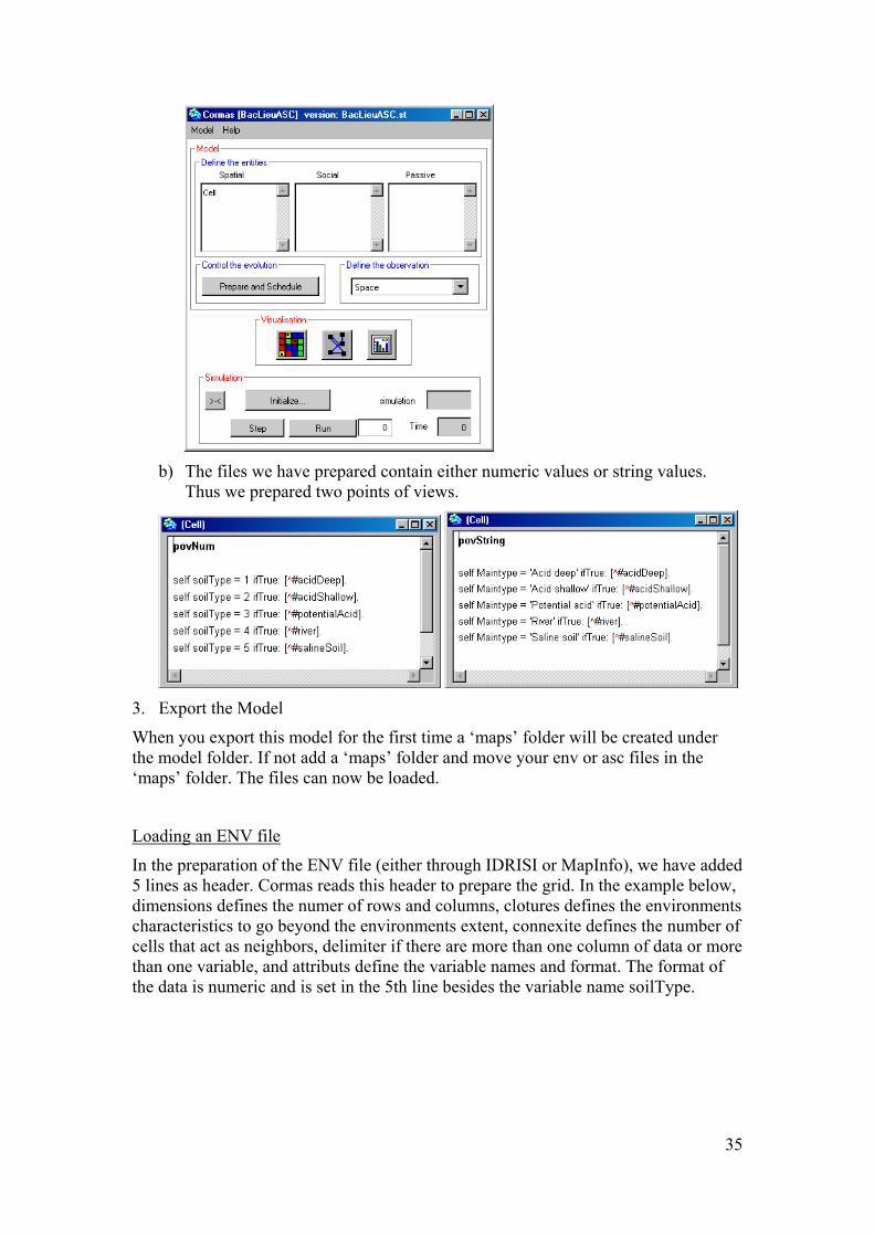
b) The files we have prepared contain either numeric values or string values.
Thus we prepared two points of views.
3. Export the Model
When you export this model for the first time a ‘maps’ folder will be created under the model folder. If not add a ‘maps’ folder and move your env or asc files in the ‘maps’ folder. The files can now be loaded.
Loading an ENV file
In the preparation of the ENV file (either through IDRISI or MapInfo), we have added 5 lines as header. Cormas reads this header to prepare the grid. In the example below, dimensions defines the numer of rows and columns, clotures defines the environments characteristics to go beyond the environments extent, connexite defines the number of cells that act as neighbors, delimiter if there are more than one column of data or more than one variable, and attributs define the variable names and format. The format of the data is numeric and is set in the 5th line besides the variable name soilType.
35

1. Choose the Spatial button in Visualization to open the Spatial environment window
2. Choose ‘Tools/Load/an environment’ and select ‘soilType.env’.
3. Choose Ok to load the environment. Notice that the grid characteristics has
change.
4. To visualize the environment, right click anywhere within the window to access the POV. Choose ‘Cell/povNum’
Loading ASC files
The difference between ENV and ASC files is that ASC files can only hold one variable as layers. So if you need to load many layers you will have many ASC files (generated by IDRARC or Arcview). Obviously each of this ASC files need to have the same content for the header.
36
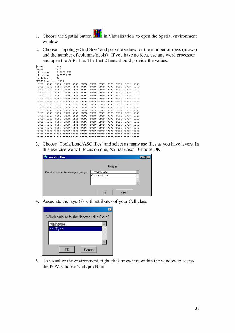
1. Choose the Spatial button in Visualization to open the Spatial environment window
2. Choose ‘Topology/Grid Size’ and provide values for the number of rows (nrows) and the number of columns(ncols). If you have no idea, use any word processor and open the ASC file. The first 2 lines should provide the values.
3. Choose ‘Tools/Load/ASC files’ and select as many asc files as you have layers. In
this exercise we will focus on one, ‘soilras2.asc’. Choose OK.
4. Associate the layer(s) with attributes of your Cell class
5. To visualize the environment, right click anywhere within the window to access
the POV. Choose ‘Cell/povNum’
37

38
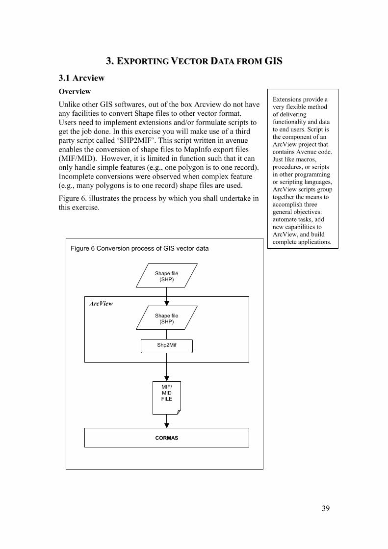
33.. EEXXPPOORRTTIINNGG VVEECCTTOORR DDAATTAA FFRROOMM GGIISS 3.1 Arcview Overview Unlike other GIS softwares, out of the box Arcview do not have any facilities to convert Shape files to other vector format. Users need to implement extensions and/or formulate scripts to get the job done. In this exercise you will make use of a third party script called ‘SHP2MIF’. This script written in avenue enables the conversion of shape files to MapInfo export files (MIF/MID). However, it is limited in function such that it can only handle simple features (e.g., one polygon is to one record). Incomplete conversions were observed when complex feature (e.g., many polygons is to one record) shape files are used.
Figure 6. illustrates the process by which you shall undertake in this exercise.
Figure 6 Conversion process of GIS vector data
Shape file (SHP)
Shp2Mif
MIF/ MID FILE
CORMAS
ArcView
Shape file (SHP)
Extensions provide a very flexible method of delivering functionality and data to end users. Script is the component of an ArcView project that contains Avenue code. Just like macros, procedures, or scripts in other programming or scripting languages, ArcView scripts group together the means to accomplish three general objectives: automate tasks, add new capabilities to ArcView, and build complete applications.
39

Objective 1. To export Arcview Shape file (SHP) to Mapinfo Interchange file (MIF/MID)
2. To be able to load and implement avenue script
Expected output MapInfo Interchange file (MIF/MID)
Requirements 1. Arcview
2. Shape file
3. SHP2MIF script (written in avenue)
4. A working knowledge about the basics of ArcView would be a plus
Procedure Configure Arcview’s environment
1. Open Arcview. By default, a New Project named ‘Untitled’ with a blank View named ‘View1’ is created. Otherwise, click on the New button in the Project Window to create a new View.
2. Define the properties for View1.
a) On the Menu bar, choose on View/Properties to access the View Properties Box.
b) Set the appropriate Map Unit (e.g., decimal degrees or meter) that would correspond to the theme’s unit of measure (this is dependent on the theme’s projection). All other input can be left as is. Choose OK
40

Add a Theme to the View
Add the Shape file ‘Ph_thanh_soil’ as a theme to the view.
It is not necessary to define the Legend but it helps in visualizing the data especially if there are more than one attribute fields associated with the theme. Refer to the article on how to define the Legend.
Load the shp2mif script
1. Make the Project window active and select the Script icon.
2. Create an empty script window (automatically named as Script1) by choosing the New button.
41

3. Choose ‘Script/Load Text File’ and browse through the work directory for
‘shp2mif.ave’ (a text file that contains instructions in Avenue for Arcview convert shape fiels to mif/mid files). Choose OK to load the script
Code Snippet of the shp2mif.ave
4. Choose ‘Script/Property’ and change the script name from’Script1’ to ‘Shp2Mif’. Choose OK when done
42
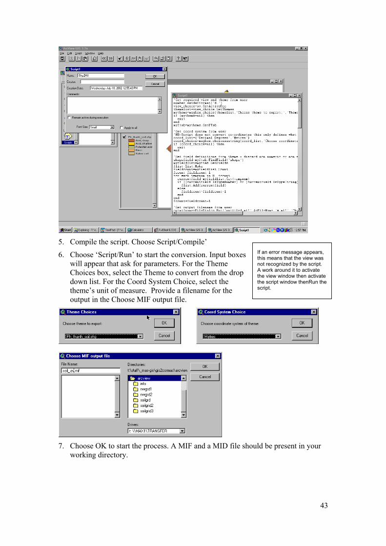
5. Compile the script. Choose Script/Compile’
If an error message appears, this means that the view was not recognized by the script. A work around it to activate the view window then activate the script window thenRun tscript.
he
6. Choose ‘Script/Run’ to start the conversion. Input boxes will appear that ask for parameters. For the Theme Choices box, select the Theme to convert from the drop down list. For the Coord System Choice, select the theme’s unit of measure. Provide a filename for the output in the Choose MIF output file.
7. Choose OK to start the process. A MIF and a MID file should be present in your
working directory.
43
3.2 IDRISI 32 Overview IDRISI 32 can convert both raster and vector data format to any GIS and non-GIS format making it a versatile application to have. In this exercise you will convert IDRISI’s vector file (VCT/VDC) to MapInfo Export File (MIF/MID). Figure 7 outlines the process you will undertake.
44

Objective To export IDRISI 32 vector file (VCT/VDC) to Mapinfo Interchange file (MIF/MID)
Expected output MapInfo Interchange file (MIF/MID)
Requirements 1. IDRISI 32
2. Vector file (VCT/VDC)
3. A working knowledge about the basics of IDRISI would be a plus
Procedure Configure IDRISI 32 working environment
1. Open IDRISI 32.
2. Choose ‘File/Data Paths’ from the Menu bar and the Project Environment box will open.
3. Set your Main Working folder by browsing through the directory where your data files are stored if necessary
Export the Vector file
1. Choose ‘File/Export/Software Specific format/MifIdris’
Figure 7 Conversion process of GIS vector data
MIF/ MID FILE
Vector File (VCT/VDC)
convert
IDRISI 32
Vector file (VCT/VDC)
CORMAS
2. In the MIFIDRIS-MapInfo MIF/Idrisi Conversion box, verify that the ‘Idrisi to Mif’ option and the ‘Export vector collection’ option are selected. Provide the filename for the ‘Input Idrisi vector collection’ and the ‘Output MIF file’.
45

3. Choose OK to start the export process. A MIF and a MID file should be present in
your working directory.
46

3.3 Mapinfo Overview MapInfo has a built-in facility to export its native vector format to MapInfo Interchange file (MIF/MID) or to an Autocad Export file (DXF). MapInfo Interchange Format (MIF) is an ASCII file format that can fully describe a MapInfo database. Both graphic and tabular data are exported into MIF files. The graphic data is in a file with a " .mif " extension, and the tabular data is in a file with an ".mid" extension. MapInfo Interchange Format files can be translated into other formats with other programs.
In this exercise you will export a MapInfo table file. Figure 8 outlines the process you will undertake
Figure 8 Conversion process of GIS vector data
Vector File (VCT/VDC)
convert
MIF/ MID FILE
CORMAS
IDRISI 32
Vector file (VCT/VDC)
47
Objective To convert MapInfo Table files (TAB) to MapInfo Interchange file (MIF/MID)
Expected output MapInfo Interchange file (MIF/MID)
Requirements 1. MapInfo
2. MapInfo Table file (TAB)
3. A working knowledge about the basics of MapInfo would be a plus
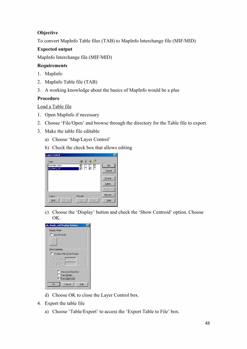
Procedure Load a Table file
1. Open MapInfo if necessary
2. Choose ‘File/Open’ and browse through the directory for the Table file to export.
3. Make the table file editable
a) Choose ‘Map/Layer Control’
b) Check the check box that allows editing
c) Choose the ‘Display’ button and check the ‘Show Centroid’ option. Choose
OK.
d) Choose OK to close the Layer Control box.
4. Export the table file
a) Choose ‘Table/Export’ to access the ‘Export Table to File’ box.
48

b) Provide a filename for the export file and choose OK to start the export
process
c) A MIF and a MID file should be present in your working directory.
49

44 CCOORRMMAASS :: IIMMPPOORRTTIINNGG VVEECCTTOORRSS Overview Importing Mif Mid data performs two actions. First it associates entities of Cormas model with the polygons included in MIF file. Then it reads the mid file and associate the data of mid file with attributes of the selected entity. For that purpose the attributes have to be created before the process
Objective 2. To be able to load MIF/MID files exported from different GIS software
Requirements 5. Visual Works
6. CORMAS
7. MIF/MID files
8. A working knowledge in CORMAS Modeling
Expected Output Cormas model with the MIF/MID files as environment
Procedure The first step is to create an ascii file. Open a text editor and write one line for each attribute. The first element is the attribute name, the second is the column number in the mif file (the information of the column is recorded in the header of the mid file), the third is the type code (asNumber for number, asText for text, asSymbol for symbols, asBoolean for boolean). These columns are separated by tabs.
Once the file is created, save it with the same name than the mif and mid file with the extension COR.
50

To import the data following the next steps you need to have previously prepared a Cormas model, with a spatial entity (it can be a cell or an aggregate) with attributes and accessing methods corresponding to the ones in th COR file. Then open the spatial interface of model and select ‘Tesselation -> irregular’
Then use the Topology menu.
A window pops.
On the left part of the window choose the filename, and on the right part choose the entity. Note that it can be an entity of any level. Check the ‘process neighbourhood’ if you want the neighbourhood to be calculated and recorded in the neighbourhood attribute of the entity.
You are then requested if the mif file includes some information. To answer open your mif file and look at the end of the definition of each polygon. You may have three lines describing the pen and brush parameters and the centroids.
51

Usually if your file has been exported from MapInfo as presented above it includes these information. From ArcView and Idrisi usually it does not contain them.
Then the polygons are displayed in the window.
52

55 CCOORRMMAASS :: EEXXPPOORRTTIINNGG AASSCC FFIILLEESS The data from Cormas can also be exported to be treated in a Gis. This is useful for instance to analyse the outputs of the simulations, to visualise them and to set the spatial references.
Objective To be able to export ASC files exported to be imported by different GIS software
Requirements Visual Works and one of the GIS softwares
CORMAS and a model
A working knowledge in CORMAS Modeling
Expected Output ASC files to be used with GIS
5.1 ArcView ArcView can import ASC files. Thus the best way is to export ASC files from Cormas
Cormas to ASC files
53
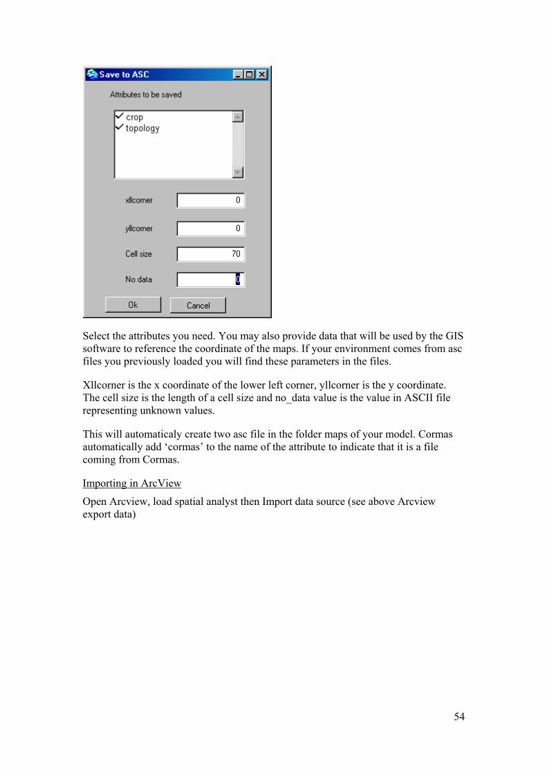
Select the attributes you need. You may also provide data that will be used by the GIS software to reference the coordinate of the maps. If your environment comes from asc files you previously loaded you will find these parameters in the files.
Xllcorner is the x coordinate of the lower left corner, yllcorner is the y coordinate. The cell size is the length of a cell size and no_data value is the value in ASCII file representing unknown values.
This will automaticaly create two asc file in the folder maps of your model. Cormas automatically add ‘cormas’ to the name of the attribute to indicate that it is a file coming from Cormas.
Importing in ArcView
Open Arcview, load spatial analyst then Import data source (see above Arcview export data)
54

A window pops, click OK.
select the name of the asc file you want to import.
Then a window pops to ask for a name to the output grid..
55

It creates two sub folders. One names ‘info’ and one named with the name of your ASC file. You will be asked if you want to add it to the current View.
56

Same process for any other asc file on the same view. At the end you can display different layers on the same view.
Save your project as a .par file.
57
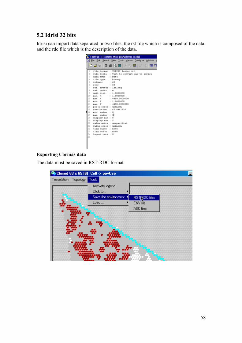
5.2 Idrisi 32 bits Idrisi can import data separated in two files, the rst file which is composed of the data and the rdc file which is the description of the data.
Exporting Cormas data The data must be saved in RST-RDC format.
58

A window pops. Resolution and Unit distance have to be fulfilled with values greater than 0.
Max X and Max Y are computed by max = (row * resolution) + min.
This window is opened to register all data needed in the description file ( the rdc file). In the inteface are not presented the number of rows and columns nor the type of each attribute because Cormas is computing it.
As a result a rdc file is created for each attribute and also a rst file which is a simple column of data.
59

Importing in Idrisi
Set the environment for the path.
60

Reformat, convert
61

Select the image input file (rst file), give an output file name. To be displayed the file has to be converted to binary so set Output file type to binary.
In the Display menu, select Display Launcher, display the binary file
62

To change the colors go to properties . Palette file select randomly one until you are happy.
For any other layer, follow the same procedure. The display is different than Arcview : for one grid there is one display.
Note : Idrisi 16 bits Apparently there are some problems with 0 values. So with Cormas it is better to export data with missing values being something else than 0.
You can use the same process to export Cormas data. Just change the extension of the file. Instead of rst file you ned a img file and instead of rdc you need a doc conversion.
You also have to delete the first line of the doc file ‘file format’ which has been added and also the two lines ‘display min’, ‘display max’.
5.3 MAPINFO At the time we prepare this text Mapinfo is not working with raster files. What can be done is prepare from Cormas a table in the appropriate format. Mapinfo can load this table. But how to link this table with a map in Mapinfo?
Comments or ideas will be welcome.
63

66.. EEXXPPOORRTTIINNGG MMIIFF MMIIDD DDAATTAA FFRROOMM CCOORRMMAASS
Objective To be able to export MIF/MID files exported to be imported by different GIS software
Requirements Visual Works and one of the GIS softwares
CORMAS and a model
A working knowledge in CORMAS Modeling
Expected Output MIF/MID files to be used with GIS
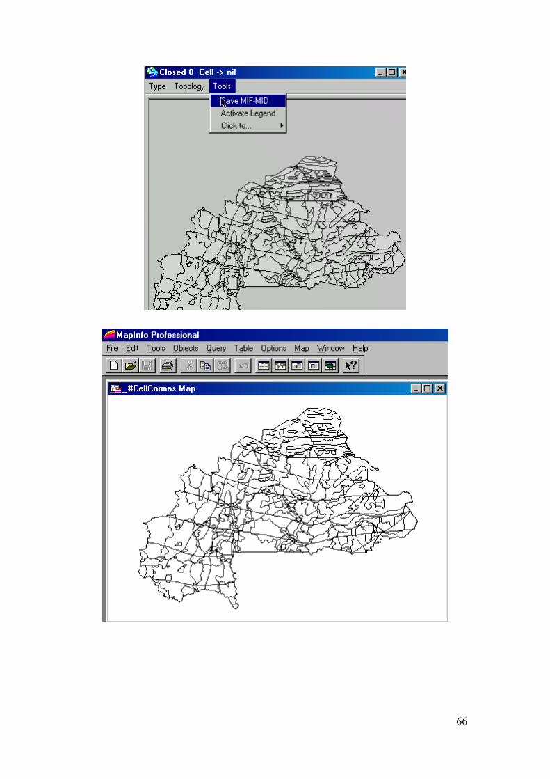
Procedure Cormas allows a simple export of Mif Mid files either for entities created on a regular grid, either for contours of entities on irregular tesselation. Once a model is loaded the spatial interface allows to export the data. Select Save-MIF MID files.
64

A window pops to ask which entity and then which attributes have to be saved. Two parameters for the type of projection and the units are also proposed by default.
The file are the saved in the maps folder of the current model. The name of the files are the name of the attribute plus ’Cormas’
Then they can be loaded in GIS software which import MIF-MID format.
The same can be done with polygons.
65
66

67