CONVENTIONAL & REVERSE MARK PUMPING UNITS · conventional & reverse mark pumping units crank ... iv...
64
P.O. BOX 849, LUFKIN, TEXAS 75902-0849 PHONE: 936/634-2211 TWX: 910-880-4201, SALES & PURCHASING INSTALLATION MANUAL CU-09 WARNING: Failure to use this manual for guidance could result in injury to personnel and/or damage to equipment. EQUALIZER BEARING EQUALIZER PITMAN GEAR REDUCER BRAKE BELT COVER BRAKE CABLE PRIME MOVER BRAKE LEVER CONVENTIONAL & REVERSE MARK PUMPING UNITS CRANK CENTER BEARING WALKING BEAM HORSEHEAD LADDER WIRELINE CARRIER BAR SAMSON POST CRANK PIN BEARING COUNTERWEIGHT BASE
Transcript of CONVENTIONAL & REVERSE MARK PUMPING UNITS · conventional & reverse mark pumping units crank ... iv...

P.O. BOX 849, LUFKIN, TEXAS 75902-0849PHONE: 936/634-2211
TWX: 910-880-4201, SALES & PURCHASING
INSTALLATION MANUAL CU-09WARNING: Failure to use this manual for guidance could result in injury to
personnel and/or damage to equipment.
EQUALIZER BEARING
EQUALIZER
PITMAN
GEAR REDUCER
BRAKE
BELT COVER
BRAKE CABLE
PRIME MOVER
BRAKE LEVER
CONVENTIONAL & REVERSE MARKPUMPING UNITS
CRANK
CENTER BEARING WALKING BEAM
HORSEHEAD
LADDER
WIRELINE
CARRIER BAR
SAMSON POST
CRANK PIN BEARING
COUNTERWEIGHT
BASE


i
WARNING
The LUFKIN Conventional and Reverse Mark Pumping Units are designed to givemany years of dependable service. Like all machines with moving parts, there are“potential” hazards associated with its use. These hazards can be reduced if themachine is properly installed, operated and maintained. All personnel who install,operate or maintain the unit must read this manual and must be trained to use themachine in an appropriate and safe manner. Should any questions arise concerningthe maintenance or operation of the machine, contact LUFKIN Industries, Inc. at 1-936/634-2211.
Do Not allow personnel to standunder moving loads or parts.
Set brake, engage pawl and chainbrake drum during installation andmaintenance to prevent movement of counterweights and cranks.
Keep clear of counterweight andcrank swing area and other partsthat may start moving.
Do Not operate pumping units with-out proper guards in place.
Do Not service well without removingthe horsehead.
Properly install the horsehead latch bolt, safety bar and/or hingepin.
Keep pumping units at least 10 feet away from all overhead wires.
Lockout/ tagout ALL energy sources.
All electrical work must be per-formed by a qualified electrician.
POTENTIAL HAZARD EFFECT PREVENTION
ELECTRICAL CONTACT
MOVING LOADS ORPARTS
Can causesevere injury or death.
Will cause severe injury or death.

ii
FOREWORD
The LUFKIN Conventional crank balanced pumping unit is a symmetrical rear mountedgeometry Class I lever system having crank counterbalance. LUFKIN’s Reverse Markunit is a conventional style pumping unit with offset geometry and phased counter-balance. The Reverse Mark is designed for operation in a clockwise direction of rotation only, when viewing the unit from the side with the well head to the right, while theConventional unit may be operated in either direction. The four bar lever system converts rotational motion at the crank to reciprocating motion at the horsehead and inturn to the down hole pump.
LUFKIN pumping units have been designed to rigid LUFKIN standards and exceed API(American Petroleum Institute) standard requirements for pumping unit design. In addition, all individual components of the unit and the unit as a whole represent the verybest engineering design, production facilities, quality and field experience that almost acentury of LUFKIN INDUSTRIES’ experience can bring to you. Your LUFKIN unit will give many years of dependable service when properly installed, maintained and operated within its load and torque ratings.
To avoid confusion, some of the more common terms used concerning pumping units are defined as follows:
Front: is the well head (horsehead) end.Rear: is the prime mover end.Left & Right: are determined by standing at the rear of the pumping unit and facing the well head.Crank Sweep or Crank Swing: is the circular area centered about the crankshaft where the cranks and counterweights will rotate when in motion.
NOTE: Some of the photographs and illustrations used in this manual are representative and may not look exactly like the parts with which you are working.

iii
i. Warnings
ii. Foreword
1. SAFETY
1.1 Hazard Identification1.2 Some Potential Hazards1.3 Commonly Used Safety Procedures
1.3.1 Installing the Brake Pawl1.3.2 Chaining the Brake Drum
1.4 Guarding of Units
1.4.1 Crank Guards1.4.2 Horsehead Guards1.4.3 Belt Guards1.4.4 Prime Mover Guards
1.5 Proper Clothing and Tools1.6 Training
2. INSTALLATION EQUIPMENT SIZING CHARTS
3. FASTENERS
3.1 “Metal-to-Metal” Grip3.2 “Elastic” Grip
4. FOUNDATION
4.1 General4.2 Types of Foundations4.3 Well Head Clearance4.4 Alignment Marks
5. UNIT INSTALLATION
5.1 Base Installation5.2 Reducer Information5.3 Crank Pin Installation5.4 Reducer Installation5.5 Reducer Alignment5.6 Crank Rotation5.7 Brake System Installation and Adjustment
5.7.1 Type “B”5.7.2 Type “A”

iv
5.8 Master Counterweight Installation5.9 Auxiliary Weight Installation5.10 Samson Post Installation5.11 Ladder Installation5.12 Leveling Center Bearing Plate5.13 Prime Mover Installation5.14 “V-Belts” Installation and Alignment5.15 Belt Cover Installation5.16 Center Bearing to Beam Assembly5.17 Equalizer Bearing to Beam Assembly5.18 Equalizer Bearing Hinge Pin Lubrication5.19 Center Bearing/Equalizer Bearing Alignment5.20 Pitman/Equalizer, Assembly5.21 Equalizer Bearing Lubrication & Hose Installation5.22 Pitman Box Lubrication5.23 Cleaning the Center Bearing Base5.24 Pitman Parallelism5.25 Center Bearing/Post Installation5.26 Pitman/Crank Pin Connection5.27 Pitman Alignment5.28 Center Bearing Lubrication & Hose Installation5.29 Preparation for Horsehead Installation5.30 Wireline Installation5.31 Wireline Bail Installation5.32 Horsehead Installation5.33 Horsehead Adjustment5.34 Unit Alignment5.35 Reducer Lubrication5.36 Bearing Assembly Lubrication5.37 Crank Guard Installation5.38 Attaching the Well Load
6. PRE-OPERATION
6.1 Direction of Rotation6.2 First Crank Revolution
7. COUNTERBALANCE ADJUSTMENT
7.1 Determining the Required Counterbalance7.2 Counterweight Adjustment
7.2.1 Cranks with tooth rack7.2.2 Cranks without tooth rack
8. STROKE CHANGE
8.1 Preparation8.2 Crank Pin Removal8.3 Crank Pin Installation8.4 Putting the Unit into Operation

v
9. WELL SERVICING
9.1 Preparation9.2 Horsehead Removal9.3 Horsehead Installation9.4 Putting the Unit into Operation
10. PREVENTIVE MAINTENANCE
11. SCHEDULED MAINTENANCE
11.1 Monthly
11.1.1 Reduce11.1.2 Structural Bearings
11.2 Quarterly
11.2.1 Belts and Sheaves11.2.2 Brake11.2.3 Brake Drum11.2.4 Brake Cable11.2.5 Crank Phase Marks
11.3 Semi-Annually
11.3.1 Reducer11.3.2 Structural Bearings11.3.3 Upper Pitman Pins11.3.4 Wireline11.3.5 Bolts11.3.6 Safety Signs
12. LUBRICANT SPECIFICATIONS
12.1 Reducer12.2 Reducer Oil Capacity12.3 Structural Bearings & Upper Pitman Pins12.4 Wireline
13. LUFKIN SERVICE
13.1 Personnel13.2 Repair and Replacement Parts
14. SAFETY SIGN REPLACEMENT
15. BASE ILLUSTRATIONS

1
INSTALLATION MANUAL
LUFKIN CONVENTIONAL AND REVERSE MARK PUMPING UNITS
1. SAFETY
Before proceeding with the installation, operation or maintenance of a pumping unit, familiarize yourself with Federal, State and Local laws, your company’s safety regulationsand the safety section of this manual. For your protection and to prevent equipment damage, please heed the product safety signs attached to the pumping unit.
1.1 HAZARD IDENTIFICATION
DANGER: Indicates an imminently hazardous situation which, if not avoided, willresult in serious injury or death.
WARNING: Indicates a potentially hazardous situation which, if not avoided, could resultin serious injury or death.
CAUTION: Indicates a potentially hazardous situation which, if not avoided, could result in minor or moderate injury or damage to the unit.
1.2 SOME POTENTIAL HAZARDS
Failure to heed the following WARNINGS could result in severe bodily injury or death to personnel:
• Pumping units have large and heavy rotating parts. Even a temporarily stationary pumping unit has components that can start moving from the effect ofgravity. Times of particular danger are during unit installation, stroke change, counterbalance change, general unit maintenance, well servicing and while taking dynamometer card readings.
Whenever performing maintenance on, or working around the pumping unit,always lockout/tagout all energy sources and secure the cranks against rotation.All personnel must stay alert and keep clear of the crank swing area and otherpotential moving parts.
• Never stand under the horsehead during installation or removal of the head.Double check the horsehead for proper installation on the walking beam, including the installation of the safety bar, hinge pin and/or the latch bolt beforerotating the unit.
Remove the horsehead before servicing the well, remembering to first removesafety bar, hinge pin and/or latch bolt.
• Do not stand under moving parts or loads being lifted. Always attach guide ropes to parts to aid in initial alignment of parts or assemblies.

2
• All electrical work must be performed by a qualified electrician. Regularly inspectand maintain electric motors, automatic timers or any other electrical device.
• Be aware of power line locations, keeping unit and service equipment at least ten feet away.
• Do not assume a stationary unit is not operational. Automatic timers can start units in motion without warning.
• LUFKIN does not recommend installation of or maintenance on pumping units during thunderstorms. Exercise extreme caution during icy conditions and otherinclement weather.
1.3 COMMONLY USED SAFETY PROCEDURES FOR SECURING CRANKS
DANGER: Do not enter the crank swing area to chain the drum or engage the pawl.
Always install the unit and perform maintenance with the cranks at the 6 o’clock positionwhen possible. If the cranks are straight down, no rotation will start if the carrier bar is notattached to the polished rod, or if the polished rod has been securely clamped at the stuffing box to hold the well load and all energy sources have been locked out/tagged out.
It is essential to prevent rotation of the cranks stopped in any position. Never use the brake alone as a safety stop. Always use as many other methods as possible for back upsalong with your company’s lockout/tagout procedure.
1.3.1 Installing the Brake Pawl (Figure 1)
Set the brake with the cranks in the desired position.
CAUTION: Abrupt braking may damagethe gear teeth in thereducer. A slow, even pullon the brake lever isrecommended.
On units equipped with the positive-stopbrake, the pawl must be engaged in a notchin the drum to prevent crank rotation.Inspect the pawl and drum prior to engagement for possible damage caused by previous misuse. Engage the pawl onlyafter the unit is stopped.
CAUTION: Do not allow the well load to rest on the pawl tooth. If this is done, you willneed a crane to lift the load in order to disengage the pawl.
Figure 1

3
Figure 2
1.3.2 Chaining the Brake Drum(Figure 2)
Thread a sturdy (never less than 3/8 grade 8 alloy) chain through the hole in the brake drumnearest the trunnion and then around the trunnion. Snug up the chain and attach the hookend around a link. Be sure the chain is working against the direction of rotation.
WARNING: Faulty chains and slings could fail and cause severe bodily injury or death.
1.4 GUARDING OF UNITS
DANGER: Contact with large moving parts will cause severe injury or death. Do not operate pumping units without proper guards in place. The purpose of guards is to provide a safety barrier between the moving parts of the pumping unit and people who are familiar with theoperation of pumping units. They also provide a barrier between themoving parts and animals. When pumping units are operated where they are accessible to the general public, it may be necessary to placethe pumping unit with guards in an enclosed area with a lockedentrance. The enclosure must prevent entry of unauthorized persons.Federal, State and local regulations may require specific types of guarding, dependent upon the location of your unit; therefore, the typeof guarding needed is known only by the user who must choose theproper guarding. It is essential that the user of the pumping unit comply with all applicable safety requirements. For additional information on guarding of pumping units, refer to API RP11ER.

4
1.4.1 Crank Guards
Crank guards are available from LUFKIN (see Figures 3 and 4). Under normal operatingcircumstances, the 48" open rail and 47” open 3-rail guards would be con¬sidered minimumguarding for people who are familiar with pumping units and who are accustomed to workingaround them. Basically, this type guard simply keeps workers from accidentally wanderingor falling into the crank sweeps. The 61" and 83" wire mesh guards would normally beconsidered adequate guarding for people familiar with the operation of pumping units andaccustomed to working around them, as well as smaller animals who might be able to movethrough the guards described above. Custom built guards are available to meet customerrequirements.
1.4.2 Horsehead Guards
Horsehead guards (see Figure 5) are available from LUFKIN. This guard is designed to keep people who are familiar with the operation of pumping units from accidentally wandering into the area below the horsehead and carrier bar. This type guard is requiredwhere the horsehead or carrier bar descends to 7 ft. or less from grade or work platform(Refer to API11ER).
1.4.3 Belt Guards
Belt guards are furnished with each unit. They are designed to cover exposed sheaves and belts and to provide a barrier between these items and people who are familiar with the operation of pumping units. Replacement belt guards are available from LUFKIN.
1.4.4 Prime Mover Guards
Exposed flywheels of prime movers must be guarded. Guards are available from LUFKIN.These guards are designed to keep people who are familiar with the operation of pumpingunits from accidentally walking or falling into the flywheel.
1.5 PROPER CLOTHING AND TOOLS
Snug fitting clothing is recommended. Remove jewelry. Wear hard hats, side-shield safetyglasses and safety shoes (see Figure 6).
Use proper tools for the job. Tools are designed for specific purposes and must be used properly. Always keep tools clean and in good condition.
Anytime you perform work at such a height that a fall could possibly inflict injury, you should wear a safety harness. When possible, use a manlift or some other type of approved safety basket.
Refer to your company’s safety regulations concerning clothing and tools.

5
Figure 3
Figure 4
Figure 5 Figure 6
6
1.6 TRAINING
It is essential that only properly trained personnel, under competent supervision, be allowed to work with this equipment. Training programs are an important part of safe and correct operation. Training also provides the knowledge necessary to maximize the performance of your equipment. LUFKIN INDUSTRIES, INC. recognizes the importance oftraining and conducts training schools to help familiarize your personnel with safe operating and maintenance procedures. These training schools are held at corporate headquarters in Lufkin, Texas. There is a small charge for this service. The dates for eachschool are available upon request by contacting your nearest LUFKIN sales office (see back cover of this manual).
2. INSTALLATION EQUIPMENT SIZING CHARTS
The following charts are a general guide to assist in selecting the proper equipment forinstalling your LUFKIN pumping unit. If there are further concerns or questions about theweight of a part, contact LUFKIN. An example for using the charts would be as follows:
What is needed to set a C-228D-213-86 pumping unit?
(1) In the top section of Table I, go to the 86'' stroke to see that the minimum hook height needed would be 23'-7''. Also, account for any additional height needed due to the bottom of the pumping unit base setting aboveground level.
(2) Also in this section of Table I, notice the weight of the unit base is 8,390 Ibs.Go to the reducer size in the lower section of Table I and see that a 228Dreducer with cranks weighs 11,820 Ibs. Since 228D and smaller reducers are normally shipped mounted to the unit base, you must add (8,390 + 11,820 = 20,210 Ibs.) to get the heaviest total lift needed.
(3) If you are moving a reducer with counterweights and auxiliary weightsattached, refer to the lower section of Table 1, third column. These weightsreflect the reducer, the largest cranks, the four largest counterweights and the maximum number of the largest auxiliary weights.

7
Table I
Approximate Weight and Hook Data for Installation Purposes
MAXIMUM +MINIMUM HOOK **APPROXIMATE WT.(LBS)STROKE HEIGHT PORTABLE GAS ENGINE BASE
216'' 33' - 9'' 15,000192'' 33' - 2'' 15,000168'' 29' - 7'' 12,035144'' 28' - 7'' 12,035120'' 27' - 6'' 11,885100'' 24' - 2'' 8,71086'' 23' - 7'' 8,39074'' 20' - 0'' 6,20564'' 17' - 2'' 4,99054'' 14' - 10'' 3,81048'' 13' - 1'' 3,00042'' 11' - 1'' 2,74036'' 10' - 10'' 2,165
+ Bottom of the unit base to the top of the horsehead with the beam horizontal
***WEIGHT W/CRANKS &*WEIGHT COUNTERBALANCE
REDUCER SIZE W/CRANKS (LBS) WEIGHTS (LBS)
1824D 33,900** 65,0501280D 28,800** 59,950912D 21,760** 52,910640D 20,460** 45,440456D 18,440** 43,420320D 16,510** 39,120228D 11,820** 25,220160D 8,630** 22,030114D 7,350** 17,23080D 4,930** 11,51057D 3,700** 8,97040D 2,710** 6,670
* LARGEST CRANK USED WITH REDUCER
** NORMALLY 228D REDUCERS AND SMALLER ARE SHIPPED MOUNTED ON THE BASE; ADD THE WEIGHT OF THE REDUCER WITH CRANKS TO THE BASE WEIGHT FOR TOTAL LIFT.
*** ASSUMING HEAVIEST COUNTERWEIGHTS & AUXILIARY WEIGHTS.

8
3. FASTENERS
3.1 “METAL-TO-METAL” GRIP
Bolting is a vital part of an oil field pumping unit. The surfaces under the bolt head, nut andthe contacting surfaces must be flat, clean and free of burrs so the bolted members join in“metal-to-metal” contact. Bolts, which are properly tightened during unit installation andretightened about a week later, will retain their grip under normal operating conditions.Improperly tightened bolts will break in fatigue and may cause serious failures and injury topersonnel. Table II gives recommended tightening torques.
Since high-capacity torque wrenches are not commonly available, the larger size bolts areusually hammered tight. Use a box-end wrench with a striking face and tighten the bolts untilthe hammer blows feel solid. Bolts will fail in fatigue from inadequate tightening rather than from being pulled in two from excessive tightening torque.
WARNING: Proper eye protection must be worn; flying metal could cause damage to the eyes.
TABLE II
Proper Tightening Torques
Nuts and Cap Screws with “Metal-to-Metal” Grip
Grade 2 Grade 5
3/8 - 16 NC 19 to 21 ft.lb. 30 to 32 ft.lb.1/2 - 13 NC 47 to 51 ft.lb. 71 to 79 ft.lb.5/8 - 11 NC 92 to 102 ft.lb. 143 to 157 ft.lb.3/4 - 10 NC 164 to 180 ft.lb. 253 to 279 ft.lb.7/8 - 9 NC 159 to 176 ft.lb. 409 to 451 ft.lb.
1 - 8 NC 238 to 262 ft.lb. 612 to 676 ft.lb.1 1/8 - 7 NC 336 to 372 ft.lb. 866 to 958 ft.lb.1 1/4 - 7 NC 475 to 525 ft.lb. 1064 to 1176 ft.lb.1 1/2 - 6 NC 826 to 912 ft.lb. 1849 to 2049 ft.lb.
3.2 “ELASTIC” GRIP
The grip is not always “metal-to-metal”. In applications such as foundation bolts, heel-clamp bolts and bolts used on various brackets, the fasteners will be subjected to cyclic loading. The tightening torques needed in these applications are extremely variable;however, they should be about two-thirds of the values given in Table II. Bolts should always be over tightened rather than under tightened.

9
4. FOUNDATION
4.1 GENERAL
The foundation should be constructed in accordance with the current foundation drawingshipped with the unit. The foundation drawing gives the minimum foundation required for soil with a minimum bearing strength of 1500 pounds per square foot. Consideration should be given to increasing the size and depth of the foundation in areas where the soilconditions are abnormally poor.
Grade the foundation site for adequate drainage and to provide a level foundation. Poordrainage usually results in the foundation settling unevenly, causing undue stresses in theunit base and subsequent failure. Refer to API RP11G for additional information about theinstallation of pumping units.
CAUTION: Poor preparation of the site and/or concrete can cause pumping unit basebreakage.
NOTE: For applications where units are elevated above grade, field modifications to crankguards and ladders will be required per API RP11ER. Upon your request, LUFKINwill design special guards and ladders based upon your special needs.
4.2 TYPES OF FOUNDATIONS
Poured concrete - poured on site Uniset - portable units onlyPrecast concrete blocks Fabricated steel pads - 2 pt. units only
Board mat - portable units only
CAUTION: Specially designed bases for the two-point pumping unit require supportonly at the front and rear of the unit. Only units that are designated as two-point are suitable for two-point foundations. Refer to the foundation drawingshipped with the unit or contact LUFKIN.
4.3 WELL HEAD CLEARANCE
Carrier bar clearance from the bottom of the steel base is shown on the foundation drawing. This should be considered when the grade height of the foundation is established. If clearance to sling a dynamometer beneath the carrier bar is desired, atleast 32 inches of clearance is required between the carrier bar and well head stuffing box,with the carrier bar at the bottom of the stroke.
The polished rod should be vertical to minimize stuffing box wear and to aid in the alignment of the unit.
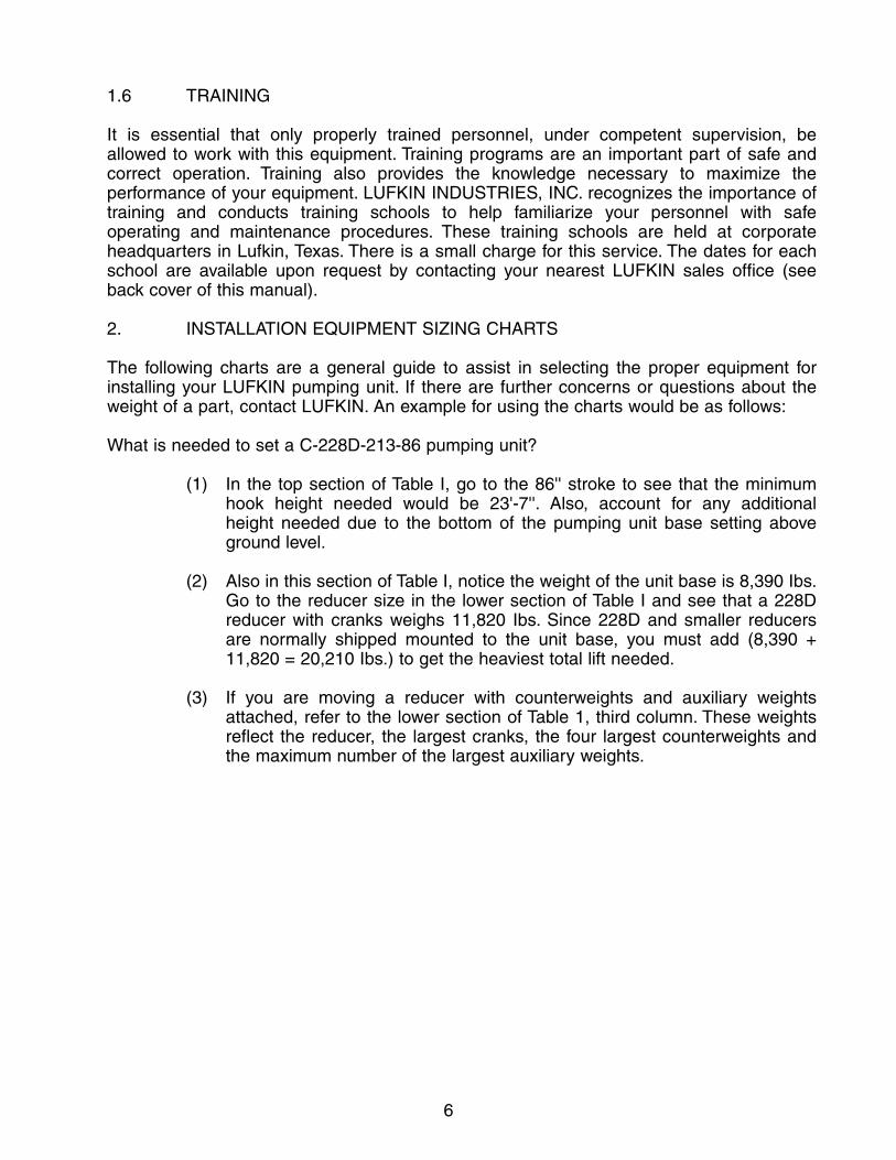
4.4 ALIGNMENT MARKS (Figure 7)
Mark a center line from the front to the rear of the foundation which extends from the center of the well through the center of the foundation. Place a cross mark perpendicularto the center line the distance shown on the foundation drawing from the center of the well
10
to the front cross member of the unit base.This distance is normally referred to as theset-back dimension. The steel base hascenter marks on the edges of the bottomflanges of the front and rear cross members. The initial alignment involvesmatching the center lines on the base andfoundation and placing the base the properdistance from the polished rod.
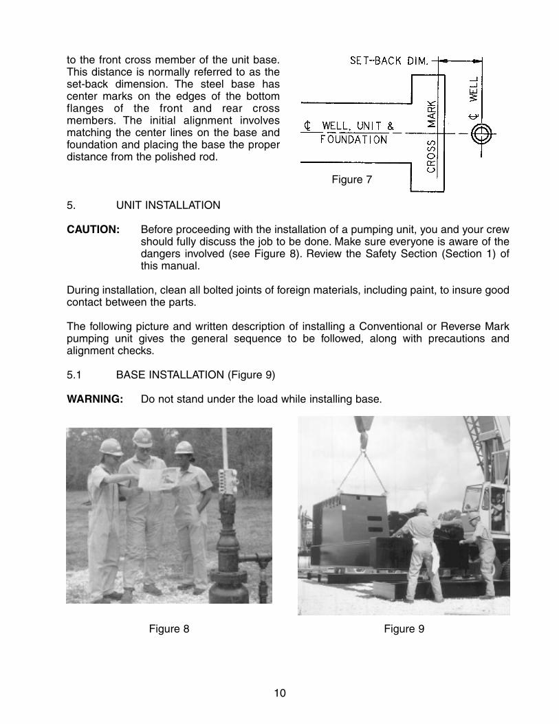
5. UNIT INSTALLATION
CAUTION: Before proceeding with the installation of a pumping unit, you and your crewshould fully discuss the job to be done. Make sure everyone is aware of thedangers involved (see Figure 8). Review the Safety Section (Section 1) of this manual.
During installation, clean all bolted joints of foreign materials, including paint, to insure goodcontact between the parts.
The following picture and written description of installing a Conventional or Reverse Markpumping unit gives the general sequence to be followed, along with precautions and alignment checks.
5.1 BASE INSTALLATION (Figure 9)
WARNING: Do not stand under the load while installing base.
Figure 7
Figure 8 Figure 9

11
Lift the base in a level position and place on the foundation. Align the center line marks onthe bottom flanges of the front and rear cross-members with the center line mark on the foundation. Position the front cross-member of the base the correct distance from the center of the well head.
If you have a two piece base (unit base and prime mover base), the prime mover base willbe positioned next. See Section 15 for an illustration of the different types of unit and primer mover bases. Remove the bolts from the joint plates. Join the bases together, tightening the bolts according to the recommendations given in Section 3. Locate and install foundation hold-down clamps and bolts. Snug tighten. Final tightening of the foundation bolts will be done after unit alignment (procedure 5.31).
5.2 REDUCER INFORMATION
Reducers are shipped from the factory with the brake linings engaged against the brake drum by a shipping screw. Due to shipping requirements, the larger reducers are shippedseparate from their bases. Also, some of the larger reducers are shipped without the crankpins mounted in the cranks. Mount the crank pins per Section 5.3.
5.3 CRANK PIN INSTALLATION
With an emery cloth, remove any paint and foreign material from the crank pin, crank pinhole and the mating surfaces between the crank and the crank pin nut. Clean these sameareas with an approved solvent (per your company’s safety policy.)
CAUTION: Improper cleaning of the crank pin and crank pin hole, as well as improper tightening of the crank pin, can cause damage to the pumping unit.
With a 1 in. brush, apply three very light stripes of non-drying machinist blue equally spaceddown the length of the pin. Remove any excess with a clean, lint-free cloth – a thick stripewill give a false indication of good contact. Install the crank pin bearing assembly in the crankpin hole without smearing the machinist blue. Thread the crank pin nut onto the crank pinand use a hammer wrench to tighten the nut until it will no longer rotate. To ensure propercontact between the crank pin and crank pin hole, use a sledge hammer to turn the wrenchone additional cotter pin notch.
Remove the crank pin bearing assembly and inspect the crank pin hole. Disregarding thearea where the groove around the crank pin was not in contact with the crank pin hole,machinist blue should be present along 85% of the hole’s length. If it is less than this, contactyour nearest Lufkin Service organization for advice.
Clean the crank pin as described above and apply a light coat of clean oil to the crank pinhole. Wipe away any excess with a clean hand. Line up the crank pin bearing assembly withthe crank pin hole. With a single motion, insert the assembly into the crank and thread thecrank pin nut onto the crank pin.
CAUTION: Do not install the crank pin without properly applying oil film in the hole.
Using a hammer wrench and your body weight, tighten the crank pin nut until it will no longerrotate. Mark the location of the hole in the crank pin on the crank pin nut. Use at least a 14-lb. sledge hammer to turn the nut two cotter pin notches. Watching carefully, hammer thewrench until the hole in the crank pin lines up with the third cotter pin notch. Continue totighten only if the nut can be turned to the next notch.

12
WARNING: Proper eye protection must be worn; flying metal could cause damage to theeyes.
Install the cotter pin. Never back the nut off to insert the cotter pin. If you have turned the nuttoo far, remove the crank pin (Procedure 8.2) and repeat all of the installation procedure.
After the crank pins are mounted in the cranks, install the reducer per Section 5.4
5.4 REDUCER INSTALLATION (Figure 10)
WARNING: The reducer with cranks is an assembly made up of heavy rotating parts.Be certain the cranks are locked against rotation. (Refer to Section 1.3 ofthis manual for proper procedures.) Do not stand under the load whileinstalling; exercise extreme care.
Figure 10
Figure 11
To install the reducer on its sub-base,attach slings to the reducer and both cranksto stabalize the load. Do not allow the slingto bear against the slow speed shaft oil sealor breakage will result. Clean the top of thesub-base. Support the reducer in a safemanner to clean the reducer’s mountingsurface. Use the centerline marks on thefront and rear of the reducer for initialalignment. Place the reducer on trhe sub-base and install the bolts from the bottom,leaving them loose so the reducer can beshifted for alignment.
5.5 REDUCER ALIGNMENT (Figure 11 )
Shift the reducer on the sub-base until thedistance from the crankshaft to the Samsonpost bolt holes on the base is the same oneach side of the unit. Tighten the bolts thatattach the reducer to the sub-base, followingthe recommendations given under“Fasteners” in Section 3.

13
5.6 CRANK ROTATION
DANGER: This machinery is made up of heavy parts that will be rotating duringthis operation. Personnel must exercise extreme care when workingaround the sweep of the cranks. Clear all personnel and objects fromthe crank sweep area before proceeding.
To rotate the cranks to a safe position,remove the chains from the reducer but notthe cranks. Disengage the positive-stoppawl, if engaged, and lock into thedisengaged position, using the locking boltand nut where provided. Clear the cranksweep area. Slowly loosen the installationand shipping screw. Use the crane to allowthe cranks to slowly rotate to bottom deadcenter. Remove the chains from the cranks.While the cranks are in this position, it issafe to connect the brake system.
NOTICE: Anytime it becomes necessary torotate the cranks to another position, attachchains to both cranks as shown in Figure12. Use a long sling to minimize excessivestress on the sling and cranks. After thecranks are in the desired position, set thebrake, engage the positive-stop pawl andchain the drum.
5.7 BRAKE SYSTEM INSTALLATION AND ADJUSTMENT
WARNING: The brake is not intended as a safety stop but is intended for operationaluse only. When maintenance is to be conducted on or around the pumpingunit, the cranks and counterweights must be securely fixed in a stationaryposition. (Refer to Section 1.3 of this manual.)
Most of our units are shipped with the type “B” brake (Figure 13). Some of the units have afabricated trunnion located horizontally from the high speed pinion, while others have thetrunnion mounted in the housing and located vertically from the high speed pinion. Featuresof the type “B” brake are: 1) an installation and shipping screw used for locking the brake for shipping purposes; 2) two adjusting nuts provided to adjust each lining independently.
Our 57D and smaller units are shipped with the type “A” brake (Figure 14). This is a shoe type brake also equipped with two adjusting nuts for independent lining adjustments.
The following procedures outline the installation of the brake control assembly and brakecable and the adjustment of the brakes as they pertain to each type:
Figure 12

14
5.7.1 Type “B” (Figure 13)
(1) Units are shipped from the factory with the brake linings engaged against the drum.
(2) Attach the brake control assembly to the base.
(3) Attach the brake cable to the base or hi-prime bracket, using the U-bolt provided.
(4) Move the brake control lever forward to locate the pin hole on the leverbetween the yoke on the end of the brake cable. Install the pin and cotter pins.
(5) The adjustment of the brake is set at the factory but may require final adjustment once the brake control lever is installed.
With the installation and shipping screw backed out flush with the lever, adjust the position of both linings with the adjusting nuts until they just clearthe drum. The spring release on the trunnion should pull the lining away from the drum near the trunnion.
Figure 13

15
(6) Using the brake control lever, engage the brake. Full engagement shouldoccur with several notches of the ratchet on the brake assembly still remaining to compensate for subsequent lining wear and cable stretch.Further adjustment to meet this condition may be made by repositioning the cable yoke on the brake control lever end. When adjusting the yoke, care should be taken not to cause the brake cable to over travel internally in the cable cover. Should this occur, move both yokes the same amount in opposite directions.
(7) Check the brake lining clearance after all adjustments are complete andreadjust if needed.
(8) Make sure the brake drum key is tight.
(9) Set the brake before continuing with unit installation.
5.7.2 Type “A” (Figure 14)
(1) Adust the position of both brake shoes by moving both adjusting nutsuntil both linings just clear the drum.
(2) Attach the brake control assembly to the base.
(3) Attach the brake cable to the base or hi-prime bracket using the U-boltprovided.
Figure 14

16
(4) Move the brake control lever forward to locate the pin hole on the leverbetween the yoke on the end of the brake cable. Install the pin and cotter pins.
(5) When the brake is disengaged, the pivot yoke of the cam should be at about a 30 degree angle to the right (see Figure 14). Simultaneously, thebrake lever would be “full off”, to the right of vertical.
(6) When the brake is fully engaged, the lower end of the cam would be vertical or up to a 30 degree angle to the left (see Figure 14).Simultaneously, the brake lever has the ratchet engaged and several notches still “available” for engagement.
(7) To achieve the proper engaged and disengaged positions of the cam andbrake lever, either or both yokes can be adjusted in or out on the ends of the brake cable.
(8) Be certain the rod end does not bottom out on the cable cover when engaging or disengaging the brake. When the yoke positions are established, tighten the jam nuts against the yokes.
(9) Make sure the brake drum key is tight.
(10) Set the brake before continuing with unit installation.
5.8 MASTER COUNTERWEIGHT INSTALLATION
WARNING: This machinery is made up of heavy parts that can rotate unexpectedly.Extreme care must be exercised when working around the sweep of thecranks.
If installing counterweights on previously assembled units, locate the cranks straight down.Set the brake, engage the pawl and chain the drum. Clean the mounting surfaces of thecounterweights and cranks of any foreign materials. Units are usually shipped with the counterweight bolts located on the topside of the cranks. Half of these will need to beremoved and placed on the opposite side of the cranks. Slide the counterweight bolts into the T-slot of the crank through the opening near the crankshaft. Using the auxiliary weight bolt holes, lift the counterweight with a sling as shown in Figure 15, or if provided, use thesingle chaining hole positioned at the center of gravity of the counterweight.
WARNING: Do not stand under any part of the load while installing counterweights. Toavoid injury to fingers and hands, hold the bolts with large channel lock pliers or other suitable tool.
On symmetrical weights, the recess for the adjusting pinion should be located toward the long end of the crank. On asymmetrical weights, the curved side must be located toward the long end of the crank (see Figure 16). Line the counterweight bolts up with the holes inthe weights and slowly swing the weight into position against the face of the crank. Install the counterweight bolt nuts and tighten according to the recommendations given in theSection 3. Install a second nut as a jam nut and hammer tighten.

17
WARNING: Improperly tightened counterweight bolts can allow the counterweights tomove on the crank. Impact movement of the counterweights could breakthrough the stop on the crank end and damage the unit or cause seriousinjury or death to personnel.
5.9 AUXILIARY WEIGHTINSTALLATION
WARNING: Do not stand under any partof the load while installing theauxiliary weights.
Install the auxiliary weights with the cranksdown. Support the weight by passing a chainthrough one of the mounting holes. Lowerthe weight in between the reducer and thecrank until a bolt hole lines up with thecorresponding hole in the mastercounterweight. Insert a bolt so that thethreads point away from the reducer (Figure17). Continue to lower the weight until theremaining holes line up. Insert another boltas described above. Remove the chain andinstall the remaining bolt(s). Tighten all boltsaccording to the recommendations givenunder “Fasteners” in Section 3. Figure 17
Figure 15 Figure 16
18
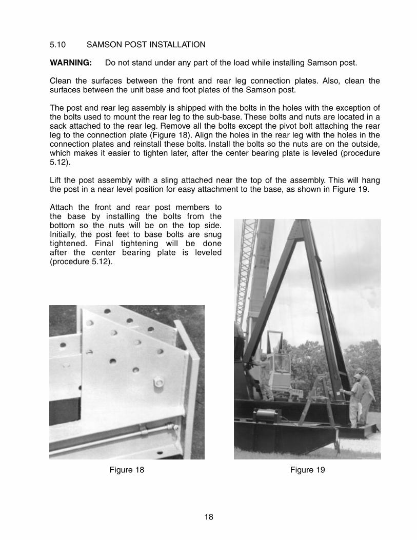
5.10 SAMSON POST INSTALLATION
WARNING: Do not stand under any part of the load while installing Samson post.
Clean the surfaces between the front and rear leg connection plates. Also, clean the surfaces between the unit base and foot plates of the Samson post.
The post and rear leg assembly is shipped with the bolts in the holes with the exception ofthe bolts used to mount the rear leg to the sub-base. These bolts and nuts are located in asack attached to the rear leg. Remove all the bolts except the pivot bolt attaching the rear leg to the connection plate (Figure 18). Align the holes in the rear leg with the holes in theconnection plates and reinstall these bolts. Install the bolts so the nuts are on the outside,which makes it easier to tighten later, after the center bearing plate is leveled (procedure5.12).
Lift the post assembly with a sling attached near the top of the assembly. This will hang the post in a near level position for easy attachment to the base, as shown in Figure 19.
Attach the front and rear post members to the base by installing the bolts from the bottom so the nuts will be on the top side.Initially, the post feet to base bolts are snug tightened. Final tightening will be done after the center bearing plate is leveled (procedure 5.12).
Figure 18 Figure 19

19
5.11 LADDER INSTALLATION
WARNING: Do not stand under any part of the load while installing ladder.
The ladder attaches directly to the Samson post or to brackets attached to the post leg asshown in Figure 20. The bottom of the ladder should be at or above the top of the base beam. Install the bolts and tighten, following the recommendations given under “Fasteners” in Section 3.
On smaller units, a clamp-on type loop is furnished with our ladders (Figure 21) to providesupport for a person when working in the area of the center bearing. The loop must belocated in a position that insures maximum safety to personnel and does not create a pinchpoint between the loop and the walking beam.
WARNING: Never use the ladder while the unit is in operation.
Figure 20 Figure 21

20
5.12 LEVELING CENTER BEARING PLATE
Check the level of the center bearing seat plate in both directions as shown in Figure 22. Ifnecessary, shim under the post legs to achieve a level center bearing seat plate.Shimming is not usually required. After leveling is achieved, hammer-tighten the bolts at allthree post feet and at the joint between the front and rear Samson post legs, following thetightening recommendations given under “Fasteners” in Section 3.
WARNING: Proper eye protection must be worn; flying metal could cause damage to the eyes.
5.13 PRIME MOVER INSTALLATION
WARNING: Do not stand under any part of the load while installing the prime mover; donot place fingers and hands between the prime mover and the side rails.
Place the slide rail bolts in the T-slots near the reducer end so the belts can be easilyinstalled after positioning the prime mover. Guide the slide rails onto the bolts. Space theslide rails to match the mounting holes of the prime mover. Install and space the mountingbolts in the T-slots on the slide rails to match the mounting holes of the prime mover. Slowlylower the prime mover onto the mounting bolts. To prevent injury to fingers and hands, usepliers or other tools to position the bolts. Install the nuts but do not tighten until the beltalignment is completed.
Some bases are tailor-made for a particular engine. These do not use slide rails, instead theengine feet mount directly to the T-slots on the base.
Figure 22 Figure 23

21
5.14 “V-BELTS INSTALLATION AND ALIGNMENT
WARNING: Be certain the prime mover cannot be started during this procedure.
Install a matched set of belts. Use the inside grooves if either sheave has an excess numberof grooves. Use a string to line up the inside faces of the sheaves as shown in Figure 23.Shift the prime mover as required and then tighten the bolts that attach the prime mover tothe slide rails. Tighten the belts by using the adjustment screws to move the prime moveruntil the belt tension is uniform across the width of the belts. Check the tension by slappingthe belts in the middle of the span. They should be lively and springy.
Tighten the bolts attaching the slide rails to the T-slots, following the recommendations givenunder “Fasteners” in Section 3.
5.15 BELT COVER INSTALLATION
WARNING: Be certain the prime mover cannot be started during this procedure.
Remove the bottom pan (Figure 24) from the belt cover and install the cover (Figure 25). Thefront support fits over two slow-speed shaft studs on the reducer and is retained by the jamnuts that are located on the reducer studs. The rear belt cover support fits on the base.Check inside the cover to be sure the sheaves and belts have adequate clearance. Thecover can be shifted sideways to adjust clearance but do not over shift and allow thesheaves to rub against the belt cover. Replace the bottom pan. Some belt covers areequipped with a center support or a wind brace, which should be attached at this time.Tighten all bolts following the recommendations given under “Fasteners” in Section 3.
NOTE: It is essential that the user of the pumping unit comply with all applicable safetyrequirements concerning the guarding of belts and sheaves. For additional informationconcerning belt guards, see API RP11ER.
Figure 25Figure 24

22
5.16 CENTER BEARING TO BEAM ASSEMBLY (Figure 26)
WARNING: Do not stand under any part of the load while moving walking beam.
Clean the surfaces between the center bearing and walking beam. Position the beam overthe center bearing assembly. Align the bolt holes. Install the bolts and snug tighten. Finaltightening of these bolts is described in procedure 5.19.
5.17 EQUALIZER BEARING TO BEAM ASSEMBLY
WARNING: Do not stand under any part of the load while moving walking beam.
Your new pumping unit is shipped with the equalizer hinge pin mounted in the walking beam lugs. To remove the pin for cleaning, loosen the pinch bolts on the walking beam lugs and remove the elastic stop nut and end cap from the equalizer hinge pin stud.
Clean the equalizer hinge pin and all of its contacting surfaces, including the bearing housing, of any rust preventive material, burrs or foreign material with a file and a safe solvent (per your company’s safety regulations) prior to assembling. After cleaning the surfaces, recoat them with a light oil to ease the assembly process. Position the walkingbeam over the equalizer and equalizer bearing assembly and slowly lower the beam until the assembly fits between the two lugs welded to the rear end of the walking beam, as shown in Figure 27. Install the hinge pin from the front end of the beam, passing it throughthe front lug first, then the equalizer bearing box and finally the rear lug on the walking beam. (On some of the smaller pumping units, the hinge pin is installed from the reartoward the front.) Next, slide the end cap onto the hinge pin stud and install the elastic stop nut. Snug tighten the hinge pin nut and the pinch bolts. Final tightening will be doneafter rotation of the unit (procedure 6.2).
Figure 26 Figure 27

23
5.18 EQUALIZER BEARING HINGE PIN LUBRICATION
Using a grease recommended in Section 12.3, lubricate the upper pitman boxes as shownin Figure 28.
5.19 CENTER BEARING/EQUALIZER BEARING ALIGNMENT (Figure 29)
After assembling the center bearing assembly and the equalizer bearing assembly to thewalking beam, carefully measure the distance between the end of the center bearing shaftand the end of the equalizer bearing shaft on both sides. For proper alignment, these distances should be the same. If necessary, loosen the center bearing saddle bolts so thecenter bearing assembly can be rotated until the shaft centers are the same on both sides.
WARNING: Proper eye protection must be worn; flying metal could cause damage to the eyes.
After obtaining the alignment, hammer-tighten the bolts between the center bearing saddleand the walking beam, per Section 3. Tighten the pusher screws on the walking beam against the center bearing and use the jam nuts to lock them in place.
CAUTION: Improper tightening of the center bearing to walking beam bolts or the pusher screws can result in broken bolts which in turn will cause severe damage to the pumping unit.
Figure 29Figure 28

24
5.20 PITMAN/EQUALIZER ASSEMBLY (Figure 30)
On top of the equalizer beam is a lubrication hose clip located only on one side of thebearing. The pitman with the lubrication line attached to it must be located on the same side.
The lubrication line grommet must be located under one of the mounting bolts of this pitman.Clean the surfaces between the pitman upper connections and the equalizer. Bolt the upperend of the pitmans to the equalizer. Snug tighten. Final tightening will be done after unitalignment (procedure 5.34).
5.21 EQUALIZER BEARING LUBRICATION AND HOSE INSTALLATION
Attach the lubrication hose to the lubrication line on the pitman and fill with grease asspecified in Section 12.3. Then attach the hose to the equalizer bearing housing (Figure 31).Only one line is needed for equalizer bearing lubrication. Check the equalizer bearinglubrication per Section 5.36.
Figure 31Figure 30

25
Figure 33
Figure 32
5.22 PITMAN BOX LUBRICATION
Using a grease recommended in Section12.3, lubricate the upper pitman boxes asshown in Figure 32.
5.23 CLEANING THE CENTERBEARING BASE
Attach slings to the walking beam asshown in Figure 33 so it can be lifted in ahorizontal position. Lift the beam highenough to clean the bottom of the centerbearing base.
WARNING: Do not stand under any partof the load while cleaning the centerbearing base.
5.24 PITMAN PARALLELISM
Continue lifting the assembly until the pitmans are off the ground. View the walking beam/pitman assembly from theside and sight from one pitman arm to theother to make sure they are parallel (Figure34). In the event the pitman arms do not line up, contact your nearest LUFKIN representative.
Figure 34

26
5.25 CENTER BEARING/POST INSTALLATION
WARNING: Do not stand under any part of the load while installing the center bearing.
Clean the top plate of the Samson post of any foreign materials. Lift the walkingbeam/pitman assembly in a level configuration and position the center bearing over the topof the Samson post. The center bearing has a male boss which fits into the hole in the topplate of the Samson post to aid in roughalignment of the center bearing to theSamson post. Install the Samson post tocenter bearing bolts and snug tighten.These bolts will be thoroughly tightenedlater, after pitman alignment is checked.
5.26 PITMAN/CRANK PINCONNECTION (Figure 35)
CAUTION: Do not hammer the pitmanlower connection onto thecrank pin bearing box. Thiscould result in damage tothe crank pin bearings.
With the crane, slowly lower the rear of thewalking beam until the pitman lower connections are aligned with the crank pins. Use ropes to guide the pitman connections to prevent contact with thecrank pin or other parts of the unit. Cleanthe contact surfaces between the pitmanlower connection and the crank pin bearingbox. The pitman ends should fit easily onthe crank pin bearing boxes.
If the pitman does not fit the crank pinsquarely, the upper pitman bolts may needto be loosened to get the proper alignment.Align the capscrew holes and install thecapscrews, tightening them per Section 3.
5.27 PITMAN ALIGNMENT
Using a tape, carefully measure thedistance between the end of the crankshaftand the nearest part of the pitman on bothsides of the gearbox, as shown in Figure 36.The two distances should be within 1/8 ofan inch of each other. In the event thepitman to crankshaft distances are not Figure 36
Figure 35

27
within these limits, rotate the walking beam by turning the center bearing on the post untilthe alignment between the pitman and the crankshaft end is satisfactory.
CAUTION: Failure to properly align the pitman to the crankshaft causes unduestresses on the structural components, which will lead to a shortenedlife of the pumping unit.
Hammer-tighten the center bearing to Samson post bolts. Remove the chains from thewaking beam.
WARNING: Proper eye protection must be worn; flying metal could cause damageto the eyes.
5.28 CENTER BEARING LUBRICATION & HOSE INSTALLATION
Attach the lubrication hoses to the lubrication lines, which are located on both front legs ofthe Samson post, and fill the hose/line assemblies with a grease recommended in Section12.3. Attach a hose to the center bearing (both sides). Check the center bearing lubricationper Section 5.36.
5.29 PREPARATION FOR HORSEHEAD INSTALLATION
DANGER: The cranks will be rotated during this operation. Exercise extremecare when working around the sweep of the cranks.
Figure 37
Attach chains to both cranks (see Notice inSection 5.6). Clear all personnel andobjects from the crank sweep area. Removethe slack in the chains by using the crane.Be sure the load is equalized. Release thebrake. Slowly raise the cranks until thewalking beam is in a horizontal position.Reset the brake, engage the pawl and chainthe drum (refer to Section 1.3 of thismanual).
5.30 WIRELINE INSTALLATION
The procedure illustrated in Figure 37involves looping the wireline around thewireline seat, which is located at the top ofthe horsehead. Loosely bolt the wirelineretainer in place over the seat and thewireline. Stretch out the wireline by pullingon the carrier bar until the carrier bar isparallel with the bottom of the horseheadand the wireline is against the seat. Tightenthe bolt holding the wireline retainer in placeper Section 3.

28
5.31 WIRELINE BAIL INSTALLATION (Figure 38)
A wireline bail is furnished on 120” stroke and larger Conventional pumping units and on allReverse Mark pumping units. The bail prevents the wireline from sliding off the side of thehorsehead in the event slack occurs in the wireline. To install the wireline bail, insert the pinson the bail into the pipe sockets on the side of the horsehead.
5.32 HORSEHEAD INSTALLATION
WARNING: Do not stand under any part of the load while positioning the horsehead.Do not place hands or fingers inside the horsehead during installation.
Before lifting the horsehead, make sure the adjusting screws are flush with the inside of theside plates (Figure 39). Lift the horsehead and clean the wireline track of any foreignmaterial. Place the horsehead on the beam, making sure the rocker plate inside the upperportion of the horsehead fits firmly against the top flange of the beam and is between the
Figure 39Figure 38
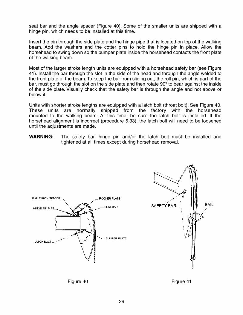
29
seat bar and the angle spacer (Figure 40). Some of the smaller units are shipped with ahinge pin, which needs to be installed at this time.
Insert the pin through the side plate and the hinge pipe that is located on top of the walkingbeam. Add the washers and the cotter pins to hold the hinge pin in place. Allow thehorsehead to swing down so the bumper plate inside the horsehead contacts the front plateof the walking beam.
Most of the larger stroke length units are equipped with a horsehead safety bar (see Figure41). Install the bar through the slot in the side of the head and through the angle welded tothe front plate of the beam. To keep the bar from sliding out, the roll pin, which is part of thebar, must go through the slot on the side plate and then rotate 90º to bear against the insideof the side plate. Visually check that the safety bar is through the angle and not above orbelow it.
Units with shorter stroke lengths are equipped with a latch bolt (throat bolt). See Figure 40.These units are normally shipped from the factory with the horsehead mounted to the walking beam. At this time, be sure the latch bolt is installed. If the horsehead alignment is incorrect (procedure 5.33), the latch bolt will need to be looseneduntil the adjustments are made.
WARNING: The safety bar, hinge pin and/or the latch bolt must be installed and tightened at all times except during horsehead removal.
Figure 40 Figure 41

30
5.33 HORSEHEAD ADJUSTMENT
With the walking beam in a horizontal position, use a level or a plumb bob, as shown in Figure 42, to check the vertical alignment of the horsehead. The horsehead may be adjusted by tightening the adjusting screws on either side of the horsehead until it is vertically aligned. After aligning the horsehead, tighten the jam nuts on the adjusting screws to maintain vertical alignment. Tighten the latch bolt on units so equipped. Refer to “Fasteners” Section 3.
NOTE: It is essential that the user of the pumping unit comply with all applicable safetyrequirements concerning the guarding of horseheads. Refer to API RP11ER. Guards areavailable from LUFKIN.
5.34 UNIT ALIGNMENT (Figure 43)
Using a rope, hold the carrier bar away from the polished rod. Do not stand under thehorsehead. Lower a plumb bob from the center of the top of the horsehead down beside thepolished rod. Alignment is achieved when the distance from the string to the center of thepolished rod is the same as the distance between the string and where the center of thewireline will travel when connected to the well load. An alternate method can be used after complete unit assembly and before starting theunit. After applying the well load to the unit, usea level to check the vertical alignment of thepolished rod in various stroke positions. Movethe entire pumping unit on its foundation ifadjustment is required.
Figure 42 Figure 43

31
After establishing the final alignment of the unit to the well:
(1 ) Attach chains to both cranks (see Notice in Section 5.6). Remove the slack to support both cranks equally. Unchain the drum and disengage the pawl.(Refer to Section 1 of this manual for safety precautions.)
After making sure the crank sweep area is clear, release the brake. Use the crane to slowly lower the cranks to the bottom dead center position.Reset the brake.
(2) Be sure all foundation hold-down clamps are installed and tighten the foundation bolts.
(3) Tighten the bolts connecting the upper pitman boxes to the equalizer.
NOTE: Do not tighten the hinge pin bolt nor the pinch bolts at the equalizeruntil after rotation of the unit (procedure 6.2).
(4) Check all other bolts to be sure they are tight.
Refer to Section 3 for bolt tightening recommendations.
5.35 REDUCER LUBRICATION (Figure 44)
See Section 12.1 for the lubrication specifications and the amount required. Check the oillevel with the dip stick located at the front of the reducer. If the oil level is low, remove theinspection cover and add oil to the proper level.
CAUTION: Damage will occur to the reducer if it is operated with the improper amountor type of lubricant.
Figure 44
32
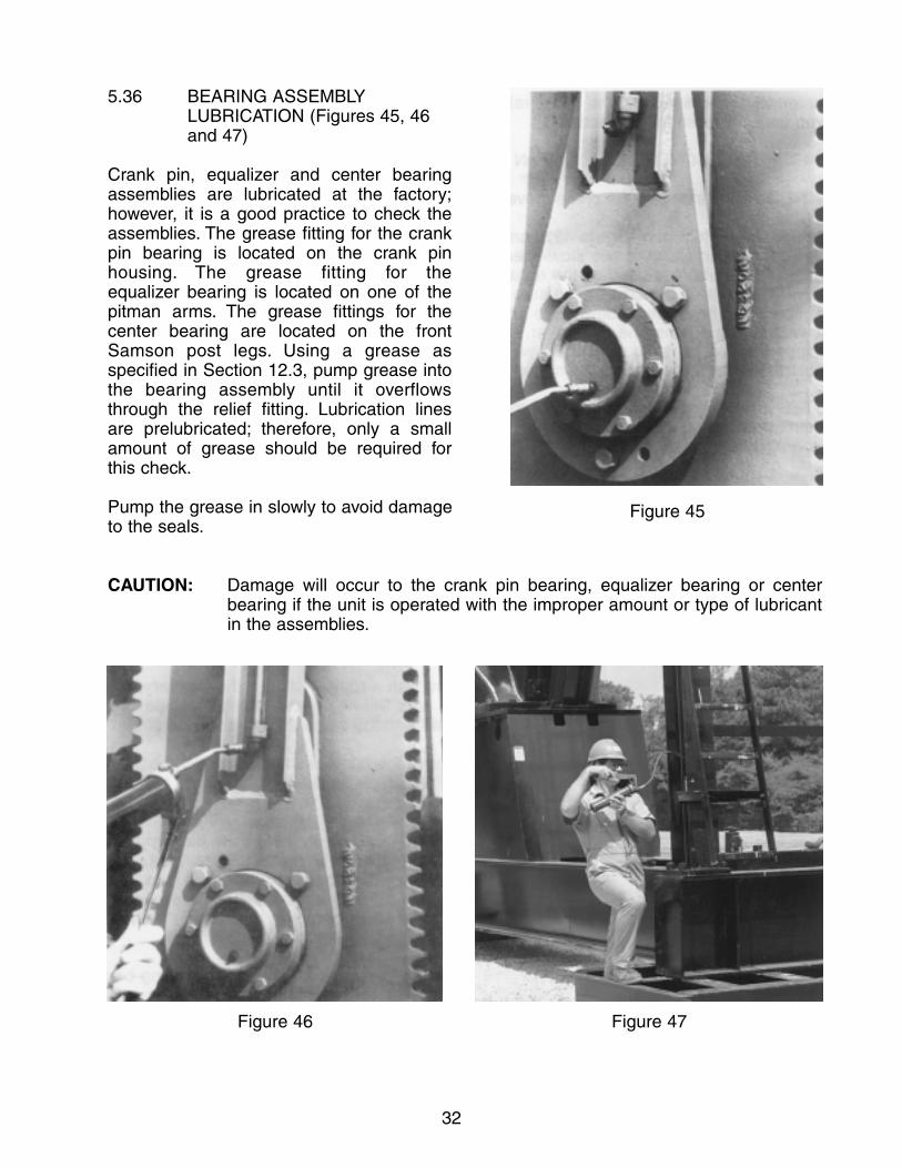
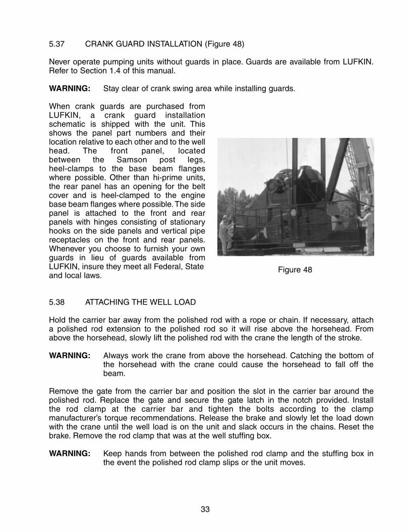
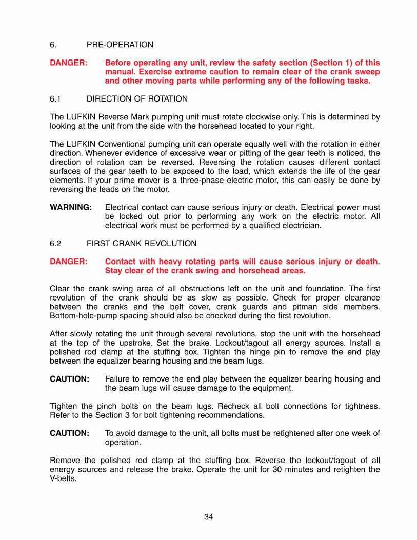
5.36 BEARING ASSEMBLY LUBRICATION (Figures 45, 46and 47)
Crank pin, equalizer and center bearingassemblies are lubricated at the factory;however, it is a good practice to check theassemblies. The grease fitting for the crankpin bearing is located on the crank pin housing. The grease fitting for the equalizer bearing is located on one of thepitman arms. The grease fittings for the center bearing are located on the frontSamson post legs. Using a grease as specified in Section 12.3, pump grease intothe bearing assembly until it overflowsthrough the relief fitting. Lubrication lines are prelubricated; therefore, only a smallamount of grease should be required for this check.
Pump the grease in slowly to avoid damageto the seals.
CAUTION: Damage will occur to the crank pin bearing, equalizer bearing or center bearing if the unit is operated with the improper amount or type of lubricant in the assemblies.
Figure 46 Figure 47
Figure 45
33
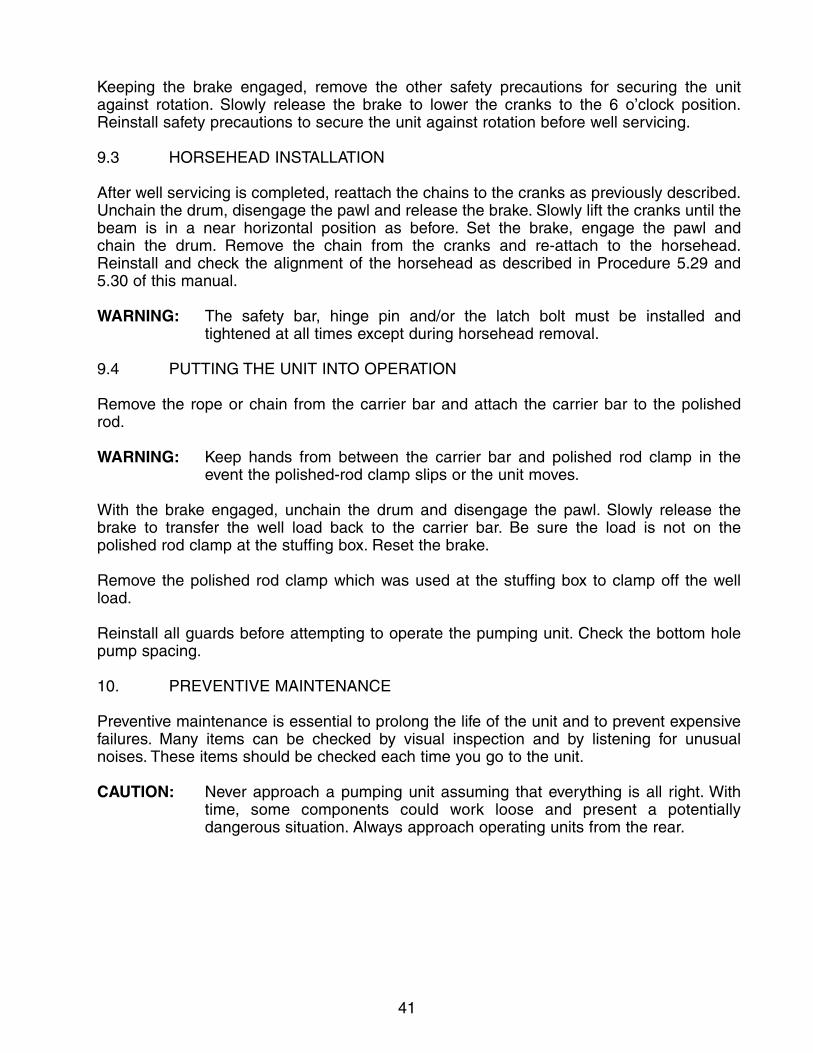
5.37 CRANK GUARD INSTALLATION (Figure 48)
Never operate pumping units without guards in place. Guards are available from LUFKIN.Refer to Section 1.4 of this manual.
WARNING: Stay clear of crank swing area while installing guards.
When crank guards are purchased fromLUFKIN, a crank guard installation schematic is shipped with the unit. Thisshows the panel part numbers and theirlocation relative to each other and to the wellhead. The front panel, located between the Samson post legs, heel-clamps to the base beam flangeswhere possible. Other than hi-prime units,the rear panel has an opening for the beltcover and is heel-clamped to the enginebase beam flanges where possible.The sidepanel is attached to the front and rearpanels with hinges consisting of stationaryhooks on the side panels and vertical pipereceptacles on the front and rear panels.Whenever you choose to furnish your ownguards in lieu of guards available fromLUFKIN, insure they meet all Federal, Stateand local laws.
5.38 ATTACHING THE WELL LOAD
Hold the carrier bar away from the polished rod with a rope or chain. If necessary, attach a polished rod extension to the polished rod so it will rise above the horsehead. From above the horsehead, slowly lift the polished rod with the crane the length of the stroke.
WARNING: Always work the crane from above the horsehead. Catching the bottom ofthe horsehead with the crane could cause the horsehead to fall off the beam.
Remove the gate from the carrier bar and position the slot in the carrier bar around the polished rod. Replace the gate and secure the gate latch in the notch provided. Install the rod clamp at the carrier bar and tighten the bolts according to the clamp manufacturer’s torque recommendations. Release the brake and slowly let the load downwith the crane until the well load is on the unit and slack occurs in the chains. Reset the brake. Remove the rod clamp that was at the well stuffing box.
WARNING: Keep hands from between the polished rod clamp and the stuffing box in the event the polished rod clamp slips or the unit moves.
Figure 48
34
6. PRE-OPERATION
DANGER: Before operating any unit, review the safety section (Section 1) of thismanual. Exercise extreme caution to remain clear of the crank sweepand other moving parts while performing any of the following tasks.
6.1 DIRECTION OF ROTATION
The LUFKIN Reverse Mark pumping unit must rotate clockwise only. This is determined bylooking at the unit from the side with the horsehead located to your right.
The LUFKIN Conventional pumping unit can operate equally well with the rotation in eitherdirection. Whenever evidence of excessive wear or pitting of the gear teeth is noticed, thedirection of rotation can be reversed. Reversing the rotation causes different contact surfaces of the gear teeth to be exposed to the load, which extends the life of the gear elements. If your prime mover is a three-phase electric motor, this can easily be done byreversing the leads on the motor.
WARNING: Electrical contact can cause serious injury or death. Electrical power must be locked out prior to performing any work on the electric motor. All electrical work must be performed by a qualified electrician.
6.2 FIRST CRANK REVOLUTION
DANGER: Contact with heavy rotating parts will cause serious injury or death.Stay clear of the crank swing and horsehead areas.
Clear the crank swing area of all obstructions left on the unit and foundation. The first revolution of the crank should be as slow as possible. Check for proper clearance between the cranks and the belt cover, crank guards and pitman side members.Bottom-hole-pump spacing should also be checked during the first revolution.
After slowly rotating the unit through several revolutions, stop the unit with the horsehead at the top of the upstroke. Set the brake. Lockout/tagout all energy sources. Install a polished rod clamp at the stuffing box. Tighten the hinge pin to remove the end play between the equalizer bearing housing and the beam lugs.
CAUTION: Failure to remove the end play between the equalizer bearing housing andthe beam lugs will cause damage to the equipment.
Tighten the pinch bolts on the beam lugs. Recheck all bolt connections for tightness.Refer to the Section 3 for bolt tightening recommendations.
CAUTION: To avoid damage to the unit, all bolts must be retightened after one week ofoperation.
Remove the polished rod clamp at the stuffing box. Reverse the lockout/tagout of all energy sources and release the brake. Operate the unit for 30 minutes and retighten the V-belts.

35
7. COUNTERBALANCE ADJUSTMENT
7.1 DETERMINING THE REQUIRED COUNTERBALANCE
Efficient operation, minimum torque loading and maximum life of a pumping unit are all a result of proper counterbalance. Counterbalance requirements can be determined veryaccurately or estimated by several methods.
DANGER: Do not enter the crank swing area or stand under the horsehead whileperforming any of the following tasks.
(1) Polished-rod dynamometer -A dynamometer card analysis is the most accurate method for determiningloading and counterbalance. This involves using a dynamometer to record the well load through a stroke cycle and then using torque factors to determine the reducer torque and counterbalance required for balanced conditions.
(2) Ammeter -A clip-on ammeter may be used to compare the upstroke and down strokecurrent on electrically powered units. When the counterbalance is adjusted so the current peaks are equal, the unit will be approximately in balance.
(3) Vacuum gauge -A vacuum gauge may be used to compare torque peaks on engine drivenunits much like the ammeter is used on electrically driven units. Vacuum pressure decreases as engine output increases.
(4) Sound of the prime mover -A rough estimate of balance can be made by listening to the characteristicsound of the prime mover as it drives the unit. Some speed change will occur as the peak loads are approached; this speed change will cause thesound of the prime mover to change.
(5) Tension in the belts -Belt tension and consequently belt stretch increases with load which causesan apportionable amount of slack in the belts on the side opposite the direction of rotation of the prime mover. A visual comparison of the belt slack or sag on the upstroke and down stroke can be used to estimate counterbalance.

36
7.2 COUNTERWEIGHT ADJUSTMENT
WARNING: Stay clear of the crank swing area and do not stand under the load whileadjusting counterweights.
7.2.1 Crank with Tooth Rack
Rotate the unit and apply the brake so thatthe crank is slightly downhill in the directionthat the weights are to be moved. Set thebrake, lockout/tagout all energy sources,engage the pawl and chain the brake drum.(Refer to Section 1.3 of this manual for proper procedures.) Loosen the counterweight bolts just enough to allow theweights to be moved. Use the pinion adjusting tool on units equipped with crankswhich have teeth, as shown in Figure 49, tomove the weights to the desired position.Some of the larger weights may have to bemoved with the aid of a crane or a pry bar.The weight on the bottom of the crank maybe moved in a like manner. After positioning the weights in the desired location, tighten the counterweight bolts and install a second nut as a jam nut.Follow the recommendations given under“Fasteners” in Section 3.
7.2.2 Cranks without Tooth Rack
Stop the unit with the cranks at the 6 o’clock (bottom dead center) position. Setthe brake, lockout/tagout all energy sources, engage the pawl and chain thebrake drum. (Refer to Section 1.3 of thismanual for proper procedures) Attachchains as shown in Figure 50. Take up theslack in the chains with a crane. Loosen the counterweight bolts just enough to move the weights. Lift or lower the weightsto the desired position and tighten the counterweight bolts. Install the second nutas a jam nut. Follow recommendations givenunder “Fasteners” in Section 3.
WARNING: Improperly tightened counterweight bolts can allow the counterweights tomove on the crank. Impact movement of the counterweights could break
Figure 49
Figure 50

37
through the stop on the crank end and damage the unit or cause serious injury or death to personnel.
8. STROKE CHANGE
WARNING: Extreme caution must be exercised during the following procedure to prevent serious personal injury. Before performing a stroke change, reviewSection 1 (the Safety Section) of this manual.
The following description of a stroke change is given while viewing the pumping unit from the side with the well head located to the right:
8.1 PREPARATION
Locate the cranks at about the 2 o’clock position and set the brake.
CAUTION: Abrupt braking may damage the gear teeth in the reducer. A slow, even pull on the brake lever is recommended.
Place a polished-rod clamp at the stuffing box and tighten according to the clamp manufacturer’s torque recommendations.
Remove the crank guards. Attach chains to the cranks (see Notice in Section 5.6). Using the crane, remove the slack from the chains. Release the brake. Using the crane, raise the cranks up enough to remove the well load from the carrier bar and set the brake.
WARNING: Keep hands from betweenthe polished rod clamp andcarrier bar in the event thepolished-rod clamp slips orthe unit moves.
Disconnect the carrier bar from the polishedrod.
Put a long rope or chain through the carrierbar and put the gate back into the carrier bar. Be sure the rope or chain is long enough so the carrier bar can be held without lifting a person off the ground. Holdthe end of the rope or chain and pull the carrier bar away from the polished rod whileeasing off the brake and slowly letting thecranks down to the 4 o’clock position (Figure 51). Set the brake.
WARNING: Stay clear of the crank swing area while performing any of the following tasks.
Figure 51

38
Disconnect or lockout/tagout all energy sources. Engage the pawl and chain the drum.(Refer to Section 1.3 of this manual for proper procedures.)
Place a safe come-a-long or ratchet-boomer (1-1/2 ton minimum) between the carrier bar and the front cross-member of the base. Place another between the equalizer and the holes on the front of the sub-base. Snug both come-a-longs or ratchet-boomers to restrainpossible movement or tilting of the walking beam which would occur once the crank pins are removed from the cranks.
8.2 CRANK PIN REMOVAL
WARNING: Proper eye protection must be worn; flying metal may cause damage to theeyes.
Using a drive nut (furnished as an optional item) is the recommended way to drive out thecrank pin. First, remove the cotter pin. Remove the crank pin nut using a box-end hammer-wrench (furnished with a set of wrenches as an option) and at least a 14-poundsledge hammer with a full length handle. Then thread the drive nut onto the pin until it bottoms out. Hammer against the head of the drive nut until the pin is loose. When the pin is loose, do not remove it from the hole. Remove the drive nut and install the original nut 3 or 4 threads deep. Follow the same procedure on the opposite crank pin.
If a drive nut is not available, then remove the cotter pin and loosen the crank pin nut as previously described. Do not remove the nut. Hammer as squarely as possible against theend of the pin. When the pin becomes loose, do not remove it from the hole. Follow the same procedure on the opposite crank pin.
Check the crank pin clearance in the hole and adjust come-a-longs accordingly so when the pins are removed they will not fall nor pull up in a sudden motion. Remove the nuts and pull the crank pins out of the holes. The pitman side member will support the crank pinbearing assembly until the pin is installed into another hole. Inspect the crank pin and holesurfaces for rust and wear. These conditions may indicate that the pin was loose. Apply rust preventive to the crank pin bore after the pin is removed.
8.3 CRANK PIN INSTALLATION
With emery cloth, remove any paint and foreign material from the crank pin, crank pin holeand the mating surfaces between the crank and the crank pin nut. Clean these same areaswith an approved solvent (per your company’s safety policy.)
CAUTION: Improper cleaning of the crank pin and crank pin hole, as well as improper tightening of the crank pin, can cause damage to the pumping unit.
Adjust come-a-longs or ratchet-boomers simultaneously to line up the crank pins with theproper holes for the stroke length desired.
With a 1 in. brush, apply three very light stripes of non-drying machinist blue equally spaceddown the length of the pin. Remove any excess with a clean, lint-free cloth – a thick stripewill give a false indication of good contact. Install the crank pin bearing assembly in the crank

39
crank pin hole without smearing the machinist blue. Thread the crank pin nut onto the crankpin and use a hammer wrench to tighten the nut until it will no longer rotate.To ensure propercontact between the crank pin and crank pin hole, use a sledge hammer to turn the wrenchone additional cotter pin notch.
Remove the crank pin bearing assembly and inspect the crank pin hole. Disregarding thearea where the groove around the crank pin was not in contact with the crank pin hole,machinist blue should be present along 85% of the hole’s length. If it is less than this, contactyour nearest Lufkin Service organization for advice.
Clean the crank pin as described above and apply a light coat of clean oil to the crank pinhole. Wipe away any excess with a clean hand. Line up the crank pin bearing assembly withthe crank pin hole. With a single motion, insert the assembly into the crank and thread thecrank pin nut onto the crank pin.
CAUTION: Do not install the crank pin without properly applying oil film in the hole.
Using a hammer wrench and your body weight, tighten the crank pin nut until it will no longerrotate. Mark the location of the hole in the crank pin on the crank pin nut. Use at least a 14-lb sledge hammer to turn the nut two cotter pin notches. Watching carefully, hammer thewrench until the hole in the crank pin lines up with the third cotter pin notch. Continue totighten only if the nut can be turned to the next notch.
WARNING: Proper eye protection must be worn; flying metal could cause damage to the eyes.
Install the cotter pin. Never back the nut off to insert the cotter pin. If you have turned thenut too far, remove the crank pin (Procedure 8.2) and repeat all of the installation procedure.
8.4 PUTTING THE UNIT INTO OPERATION
With the brake engaged, remove the come-a-longs or ratchet-boomers. Keeping the brakeengaged, unchain the drum and disengage the pawl.
Hold the carrier bar away from the polished rod with the rope or chain and slowly release the brake to let the cranks go to bottom dead center. Set the brake. If necessary, attach a polished rod extension to the polished rod so it will rise above the horsehead. From abovethe horsehead, slowly lift the polished rod with the crane until the carrier bar can be reattached below the upper polished rod clamp.
WARNING: Always work the crane from above the horsehead. Catching the bottom of the horsehead with the crane could cause the horsehead to fall off the beam.
Remove the rope or chain from the carrier bar and attach the carrier bar to the polished rod. Slowly let the polished rod down until the well load is on the unit and not on the crane.Remove the polished rod clamp which was used at the stuffing box to clamp off the well load.
WARNING: Keep hands from between the carrier bar and polished rod clamp in the event the polished rod clamp slips or the unit moves.
Reinstall the crank guards. After a stroke length change, check the bottom hole pump spacing. Also, the counterbalance should be checked and the weights repositioned asrequired for proper balancing. See Section 7 for counterbalance adjustment.

40
9. WELL SERVICING
DANGER: Before performing any task around a pumping unit, refer to the safetysection of this manual (Section 1). All mechanical sucker rod pumping units, of necessity, have rotating parts. Even a temporarily stationary pumping unit has components which can start moving fromthe effect of gravity. It is essential to prevent rotation of the cranksstopped in any position for the purpose of service or maintenance.
9.1 PREPARATION
WARNING: Do not attempt to service the well without first removing the horsehead.
With the well head to the right, stop the unit with the cranks in about the eight o’clock position and set the brake. Engage the pawl. Lockout/tagout all energy sources.
CAUTION: Abrupt braking may damage the gear teeth in the reducer. A slow, even pull on the brake lever is recommended.
To clamp off the well load, place a polished-rod clamp at the stuffing box and tighten according to the clamp manufacturer’s torque recommendations.
Remove the crank guards.
Attach chains to the cranks. See Notice in Section 5.6. Using the crane, remove the slackfrom the chains. Remove the pawl and release the brake. Slowly lift the cranks until the walking beam is in a near level position. Reset the brake, engage the pawl and chain thedrum. (Refer to Section 1.3 of this manual for proper procedures.)
Disconnect the carrier bar from the polished rod.
WARNING: Keep hands from between the polished rod and carrier bar in the event thepolished-rod clamp slips or the unit moves.
Put a long rope or chain through the carrier bar and put the gate back into the carrier bar.Be sure the rope or chain is long enough so the carrier bar can be held without lifting a person off the ground.
9.2 HORSEHEAD REMOVAL
WARNING: Under no circumstances should well servicing be attempted without firstremoving the horsehead. Be certain to remove the latch bolt, safety bar and/or the hinge pin before attempting to remove the horsehead. Do not stand under any part of the load while lifting.
Attach the chain to the horsehead. Back off the adjusting screw on either side of the horsehead until they are flush with the side plates. Remove the latch bolt, safety bar and/or hinge pin. While holding the carrier bar away from the polished rod, slowly lift thehorsehead from the beam. Place the horsehead on the ground a safe distance from the work area.
41
Keeping the brake engaged, remove the other safety precautions for securing the unit against rotation. Slowly release the brake to lower the cranks to the 6 o’clock position.Reinstall safety precautions to secure the unit against rotation before well servicing.
9.3 HORSEHEAD INSTALLATION
After well servicing is completed, reattach the chains to the cranks as previously described.Unchain the drum, disengage the pawl and release the brake. Slowly lift the cranks until thebeam is in a near horizontal position as before. Set the brake, engage the pawl and chain the drum. Remove the chain from the cranks and re-attach to the horsehead.Reinstall and check the alignment of the horsehead as described in Procedure 5.29 and 5.30 of this manual.
WARNING: The safety bar, hinge pin and/or the latch bolt must be installed and tightened at all times except during horsehead removal.
9.4 PUTTING THE UNIT INTO OPERATION
Remove the rope or chain from the carrier bar and attach the carrier bar to the polished rod.
WARNING: Keep hands from between the carrier bar and polished rod clamp in the event the polished-rod clamp slips or the unit moves.
With the brake engaged, unchain the drum and disengage the pawl. Slowly release the brake to transfer the well load back to the carrier bar. Be sure the load is not on the polished rod clamp at the stuffing box. Reset the brake.
Remove the polished rod clamp which was used at the stuffing box to clamp off the well load.
Reinstall all guards before attempting to operate the pumping unit. Check the bottom holepump spacing.
10. PREVENTIVE MAINTENANCE
Preventive maintenance is essential to prolong the life of the unit and to prevent expensivefailures. Many items can be checked by visual inspection and by listening for unusual noises. These items should be checked each time you go to the unit.
CAUTION: Never approach a pumping unit assuming that everything is all right. Withtime, some components could work loose and present a potentially dangerous situation. Always approach operating units from the rear.
42
The following visual inspections are recommended before approaching the unit:
(1) Look at both crank pins to see if they may have worked loose.
(2) On units which are driven by slow-speed engines, look to see if the flywheel is loose.
(3) Look at the counterweights to be sure they are tight.
(4) Look at the center bearing to be sure it has not worked loose.
(5) Inspect the vertical alignment of the unit with the well. See if the polished rod is working to one side of the stuffing box. Also, visually compare the distance between the pitman side-members and the cranks on each side ofthe unit. Check to see that the wireline is tracking properly on the horsehead. Also, look for obvious broken strands of wire fraying from the wireline. A change in alignment can be caused if the base shifts on the foundation due to loose hold-down bolts. Misalignment can also result from a foundation that has settled to an unlevel position.
(6) Look for any obviously loose or missing bolts. Loose bolts will eventually fail in fatigue. This is the major cause of most pumping unit failures. Loosebolts can usually be located by looking for rust at the bolted joint and bychecking for visual movement.
If any of the above conditions exist, the unit must be shut down immediately and the problem corrected.
WARNING: Do not perform any task on the unit until you review the safety section of this manual (Section 1). The cranks and counterweights must be securedagainst rotation.
11. SCHEDULED MAINTENANCE
There are several items that need checking on a regular basis to help extend the life of your pumping unit.
WARNING: Always secure the cranks against rotation or movement before performingany maintenance or while working around the pumping unit. Review the safety section (Section 1) of this manual. Do not use only the brake as a safety stop. The brake is intended for operational use only.
11.1 MONTHLY
11.1.1 Reducer
Check the reducer oil level. Remove the dipstick located at the front of the reducer. The oil level should be between the low and full mark on the dipstick. Loss of oil from the reducer is usually caused by seal leakage at the shafts or leakage at the parting line. If the

43
oil level is low, remove the inspection cover and add oil to the proper level. (Refer to Section 12.1 for lubricant specifications.)
11.1.2 Structural Bearing Assemblies
Visually check the crank pin bearings, equalizer bearing and center bearing for seal leaks.Do not confuse grease discharge from the bearing housing vents with seal leakage.
11.2 QUARTERLY
11.2.1 Belts and Sheaves
Belt alignment and tension should be checked and adjusted to prolong belt life. Under normal use belts will stretch and wear. Belts need replacing once they have exceeded their allowable stretch. Belt manufacturers suggest running new belts 30 minutes and thenretightening. (Consult your belt supplier.) Refer to procedure 5.33.
Also, check the sheaves for wear, chips and cracks. Replace them if any of these conditions exist. Keeping sheaves in good condition will prolong belt life.
11.2.2. Brake
Inspect the brake lining for wear and clearance adjustment. When the brake control lever is fully engaged, there should be several notches left on the ratchet. If adjustment is required, follow the instructions that pertain to the type brake existing on the unit.
Type “B” (Figure 52)
Some units in the field have the type “B” brake. Before adjusting the brake, refer to Section 1.3 of this manual for proper safety precautions.
(1) Stop the unit with the long end of the crank in the 6 o’clock position.Lockout/tagout all energy sources. Clamp the polished rod at the stuffing box. Engage the positive stop pawl. Chain the equalizer down to the sub-base.
(2) Position the brake lever in its forward (or disengaged) position.
(3) Adjust the position of both linings with the adjusting nuts until they just clearthe drum. The spring release on the trunnion should pull the lining away from the drum near the trunnion.
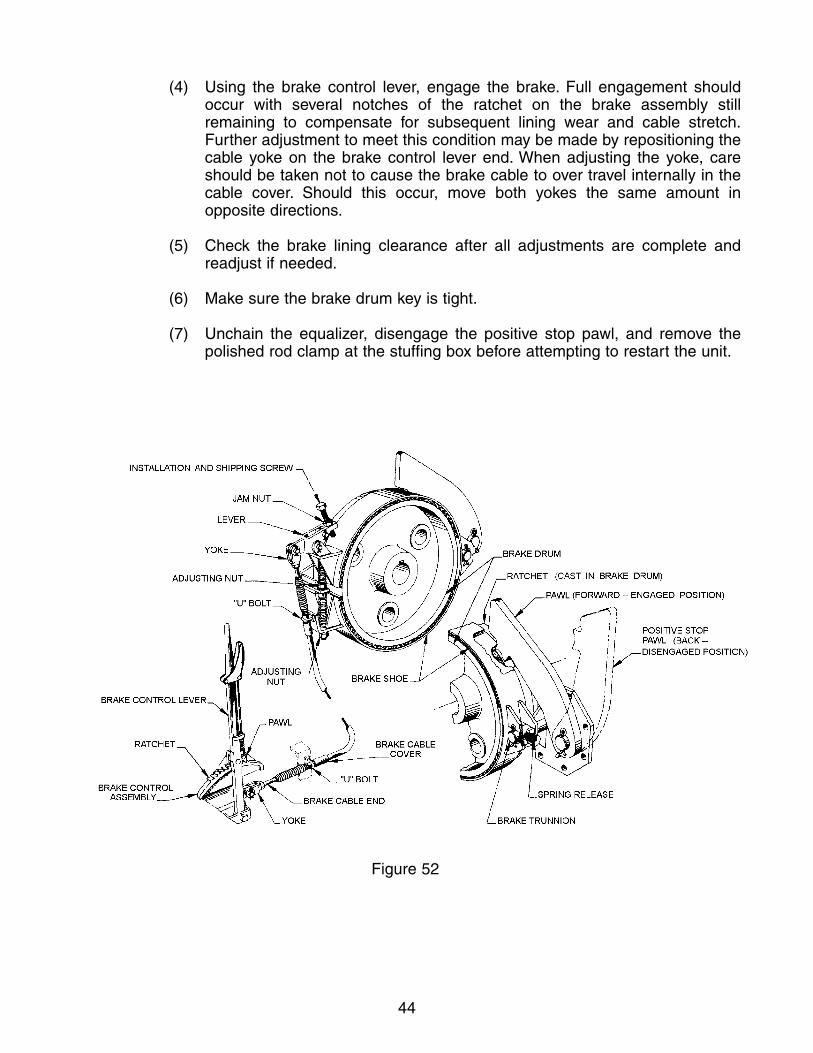
44
(4) Using the brake control lever, engage the brake. Full engagement shouldoccur with several notches of the ratchet on the brake assembly still remaining to compensate for subsequent lining wear and cable stretch.Further adjustment to meet this condition may be made by repositioning thecable yoke on the brake control lever end. When adjusting the yoke, careshould be taken not to cause the brake cable to over travel internally in thecable cover. Should this occur, move both yokes the same amount in opposite directions.
(5) Check the brake lining clearance after all adjustments are complete and readjust if needed.
(6) Make sure the brake drum key is tight.
(7) Unchain the equalizer, disengage the positive stop pawl, and remove the polished rod clamp at the stuffing box before attempting to restart the unit.
Figure 52

45
Figure 53
Figure 54

46
Type “C” (Figures 53 and 54)
Some units in the field have the type “C” brake. This type has some top and some side mounted trunnions. It has a single adjusting nut that adjusts both brake linings simultaneously. Before adjusting the brake, refer to Section 1.3 of this manual for proper safety precautions.
(1) Stop the unit with the long end of the crank in the 6 o’clock position.Lockout/tagout all energy sources. Clamp the polished rod at the stuffing box. Engage the positive-stop pawl. Chain the equalizer down to the sub-base.
(2) Position the brake lever in its forward (or disengaged) position.
(3) Adjust the position of both brake linings by loosening the jam nut and moving the adjusting nut until both linings just clear the drum. Retighten thejam nut.
(4) Using the brake control lever, engage the brake. Full engagement shouldoccur with several notches of the ratchet on the brake assembly still remaining to compensate for subsequent lining wear and cable stretch.Further adjustment to meet this condition may be made by repositioning thecable yoke on the brake control lever end. When adjusting the yoke, careshould be taken not to cause the brake cable to over travel internally in thecable cover. Should this occur, move both yokes the same amount in opposite directions.
(5) Make sure the brake drum key is tight.
(6) Unchain the equalizer, disengage the positive stop pawl and remove the polished rod clamp at the stuffing box before attempting to restart the unit.
Type “A”
Some smaller and older units in the field may have the shoe type brake (see Figure 55). Before adjusting the brake, refer to Section 1.3 of this manual for proper safety precautions.
(1) Stop the unit with the long end of the crank in the 6 o’clock position.Lockout/tagout all energy sources. Clamp the polished rod at the stuffing box. Chain the equalizer down to the sub-base.
(2) Position the brake lever in its forward (or disengaged) position.
(3) Adjust the position of both brake shoes by moving both adjusting nuts untilboth linings just clear the drum.
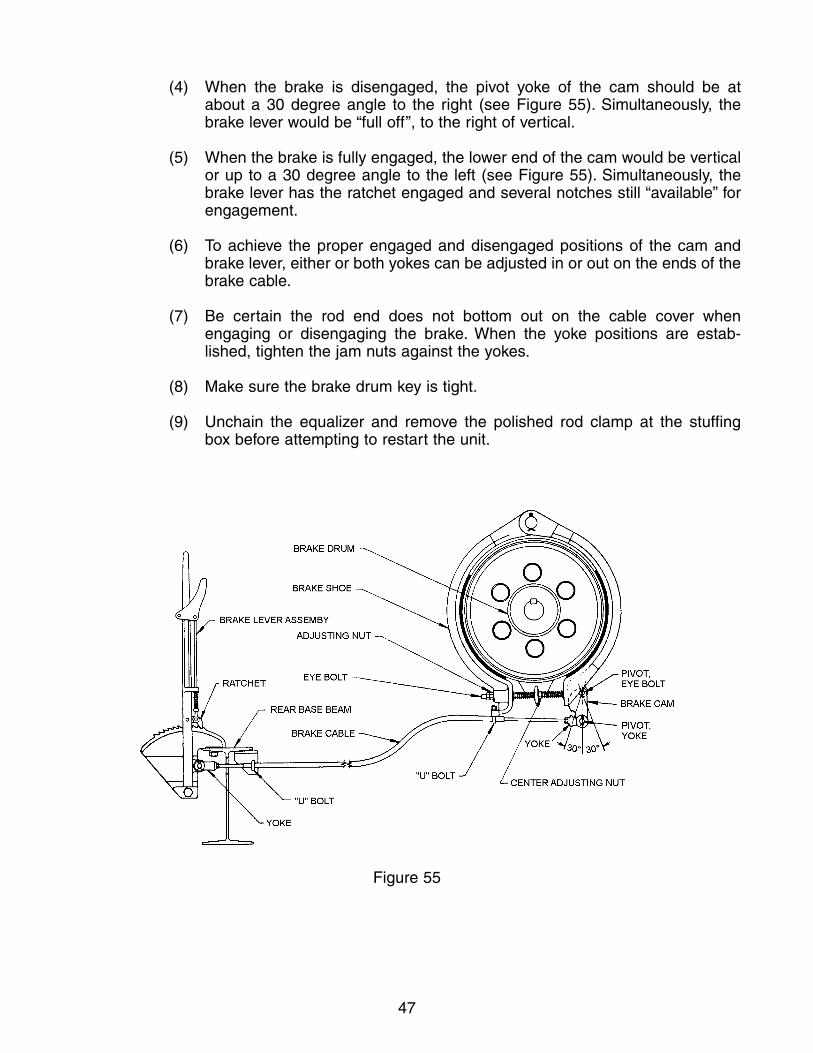
47
(4) When the brake is disengaged, the pivot yoke of the cam should be at about a 30 degree angle to the right (see Figure 55). Simultaneously, thebrake lever would be “full off”, to the right of vertical.
(5) When the brake is fully engaged, the lower end of the cam would be verticalor up to a 30 degree angle to the left (see Figure 55). Simultaneously, thebrake lever has the ratchet engaged and several notches still “available” forengagement.
(6) To achieve the proper engaged and disengaged positions of the cam andbrake lever, either or both yokes can be adjusted in or out on the ends of thebrake cable.
(7) Be certain the rod end does not bottom out on the cable cover when engaging or disengaging the brake. When the yoke positions are estab-lished, tighten the jam nuts against the yokes.
(8) Make sure the brake drum key is tight.
(9) Unchain the equalizer and remove the polished rod clamp at the stuffing box before attempting to restart the unit.
Figure 55
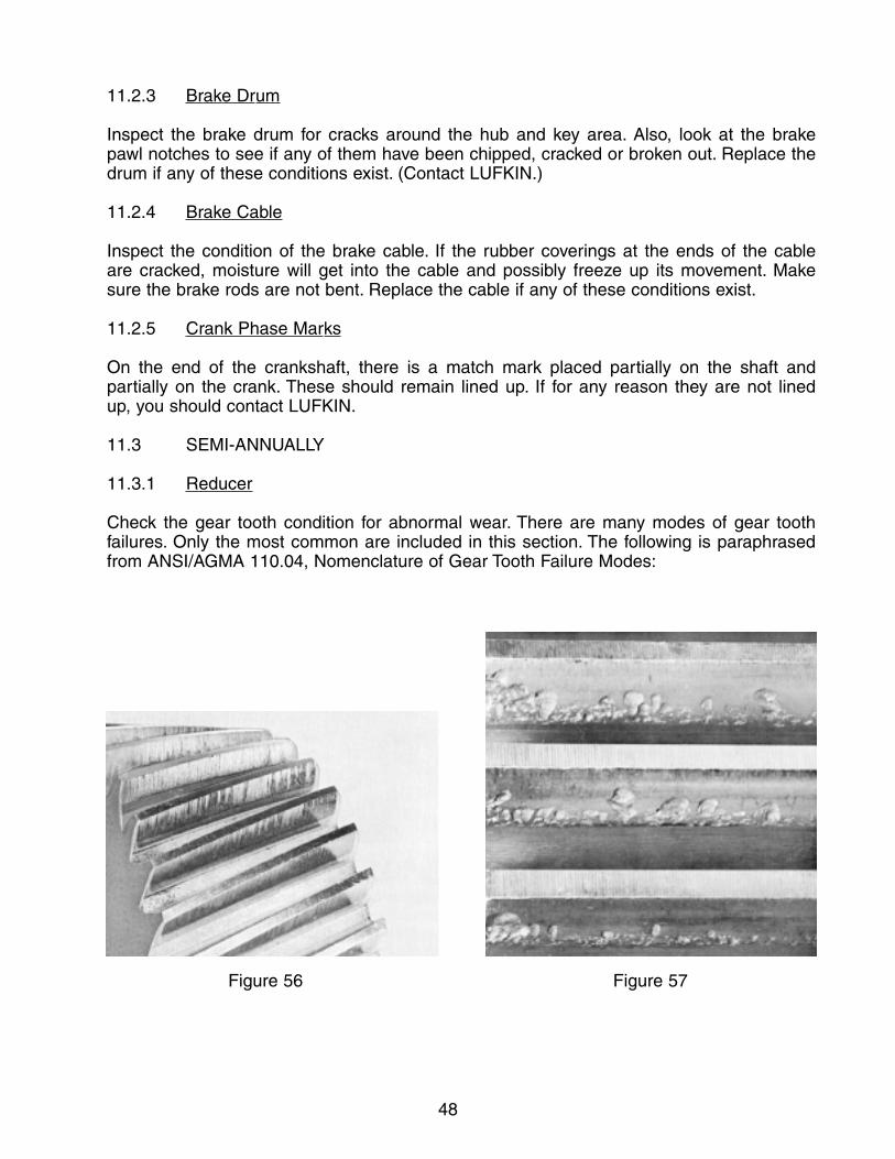
48
11.2.3 Brake Drum
Inspect the brake drum for cracks around the hub and key area. Also, look at the brake pawl notches to see if any of them have been chipped, cracked or broken out. Replace thedrum if any of these conditions exist. (Contact LUFKIN.)
11.2.4 Brake Cable
Inspect the condition of the brake cable. If the rubber coverings at the ends of the cable are cracked, moisture will get into the cable and possibly freeze up its movement. Make sure the brake rods are not bent. Replace the cable if any of these conditions exist.
11.2.5 Crank Phase Marks
On the end of the crankshaft, there is a match mark placed partially on the shaft and partially on the crank. These should remain lined up. If for any reason they are not lined up, you should contact LUFKIN.
11.3 SEMI-ANNUALLY
11.3.1 Reducer
Check the gear tooth condition for abnormal wear. There are many modes of gear tooth failures. Only the most common are included in this section. The following is paraphrasedfrom ANSI/AGMA 110.04, Nomenclature of Gear Tooth Failure Modes:
Figure 56 Figure 57

49
(1) Score marks on the teeth are an indication that the film thickness of the oil isinsufficient for the loads imposed. Score marks are vertical marks on the teeth fromthe top of the teeth to the root (see Figure 56).
(2) Pitting is a type of surface fatigue which occurs when the endurance limit of thematerial is exceeded. It shows up as small cavities along the surface of the teeth.The type of pitting shown in Figure 57 is usually caused by torque overload.Continued overload may result in gear tooth failures.
For more detailed descriptions, illustrations, causes, and remedies, see ANSI/AGMA Standard 110.04. Note also, Figures 56 and 57 were extracted from “AGMA StandardNomenclature of Gear Tooth Failure Modes” (AGMA 110.04), with the permission of the publisher: The American Gear Manufacturer’s Association, Suite 1000, 1901 North Fort Myer Drive, Arlington, Virginia 22209.
Before the reducer oil has a chance to settle, collect a typical sample (about a pint) in a transparent container. A visual inspection will expose possible dirt, sludge, water emulsion or other forms of contamination. Also, keep a sample of new oil for comparisons. If the lubricant has any of the following conditions, check with your oil supplier aboutreplacement:
(1) An acid or burnt odor would indicate oxidation of the oil to the point that it should be replaced.
(2) If sludge is observed in the used sample, the oil should either be replaced or filtered to remove the sludge. Sludge is usually found in gear units that have not had their lubricants changed in a long time.
(3) If water is found in the sample, the water should be completely drained from the sump. The presence of water in used oil can be detected by placing a drop or two on a heated metal surface. Bubbling and spattering will occur with as little as 0.1% of water present in the oil. More than approximately 0.2% water by volume suggests an oil change.
If a rigorous laboratory test of the oil is not practical, then replace the oil every 18 months as a precaution against a change in viscosity, a loss of the additive package or an increasein the acidic condition of the oil.
For lubricant specifications, see Section 12.1 of this manual.
11.3.2 Structural Bearings
Lubricate the structural bearings with grease as recommended in Section 12.3 of thismanual. Grease fittings are located at ground level. Pump grease in slowly to avoid pushing out the oil seals. Discharge from the vents located on each bearing housingindicates that the housing is full.

50
11.3.3 Upper Pitman Pins
Lubricate the upper pitman pins with grease as recommended in Section 12.3 of thismanual. The grease fittings are located on top of the upper pitman boxes at the equalizer.The purpose of these pins is to allow the pitmans to swing away from the equalizer during unit assembly, unit disassembly and during stroke changes.
11.3.4 Wireline
Look for broken strands of wire fraying from the wireline. A rusty wireline should be cleaned and coated with a wireline lubricant as specified in Section 12.4.
11.3.5 Bolts
Check all bolts. Retighten as recommended in Section 3 of this manual. Loose bolts willeventually fail, which is the cause of most pumping unit failures.
11.3.6 Safety Signs and Tags
LUFKIN uses safety signs and decals for your protection. In the event any of the signs or decals are destroyed, damaged or become unreadable for any reason, refer to Section 14for replacement part numbers and their location on the unit.
12. LUBRICANT SPECIFICATIONS
12.1 REDUCER
For ambient temperatures down to 0°F use an AGMA No. 5 EP (ISO VG220) premium mild,extreme-pressure lubricant (preferably a sulphur-phosphorous type) with rust and oxidationinhibitors and an anti-foam agent. The pour point of the oil should be 5°F or lower. Forextremely cold temperature applications (down to -30°F), use an AGMA No. 4 EP (ISO VG150)premium mild, extreme-pressure lubricant (preferably sulphur-phosphorous type) with rust andoxidation inhibitors and an anti-foam agent. The pour point of the oil should be 15°F or less.
Synthetic gear lubricant may be required when units are operated intermittently or shut downfor periods of time while subjected to ambient temperatures below 0°F. In comparison tomineral-based products, the viscosity of synthetic oil is less sensitive to temperature changes.Like their conventional counterparts, these should also be extreme-pressure lubricants thatcontain additives to reduce corrosion and foaming. The higher cost associated with syntheticsshould be evaluated relative to the operator’s need for these characteristics.
12.2 REDUCER OIL CAPACITY
MODEL CAPACITY MODEL CAPACITY
1824D 165 GAL. 228D 34 GAL.1280D 120 GAL. 160D 22 GAL.912D 107 GAL. 114D 17 GAL.640D 70 GAL. 80D 17 GAL.456D 55 GAL. 57D 13 GAL.320D 50 GAL. 40D 7 GAL.
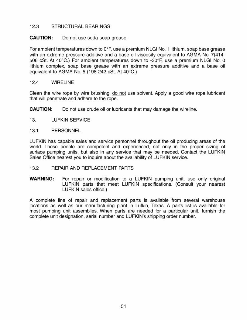
51
12.3 STRUCTURAL BEARINGS
CAUTION: Do not use soda-soap grease.
For ambient temperatures down to 0°F, use a premium NLGI No. 1 lithium, soap base greasewith an extreme pressure additive and a base oil viscosity equivalent to AGMA No. 7(414-506 cSt. At 40°C.) For ambient temperatures down to -30°F, use a premium NLGI No. 0lithium complex, soap base grease with an extreme pressure additive and a base oilequivalent to AGMA No. 5 (198-242 cSt. At 40°C.)
12.4 WlRELINE
Clean the wire rope by wire brushing; do not use solvent. Apply a good wire rope lubricant that will penetrate and adhere to the rope.
CAUTION: Do not use crude oil or lubricants that may damage the wireline.
13. LUFKIN SERVICE
13.1 PERSONNEL
LUFKIN has capable sales and service personnel throughout the oil producing areas of theworld. These people are competent and experienced, not only in the proper sizing of surface pumping units, but also in any service that may be needed. Contact the LUFKIN Sales Office nearest you to inquire about the availability of LUFKIN service.
13.2 REPAIR AND REPLACEMENT PARTS
WARNING: For repair or modification to a LUFKIN pumping unit, use only original LUFKIN parts that meet LUFKIN specifications. (Consult your nearest LUFKIN sales office.)
A complete line of repair and replacement parts is available from several warehouse locations as well as our manufacturing plant in Lufkin, Texas. A parts list is available for most pumping unit assemblies. When parts are needed for a particular unit, furnish the complete unit designation, serial number and LUFKIN’s shipping order number.

52
14. SAFETY SIGNREPLACEMENT
Tore
plac
eth
ese
sign
sor
deca
ls,s
uppl
yLU
FKIN
with
the
unit
orde
rnum
berl
ocat
edon
the
APIr
educ
erpl
ate
orth
eAP
Istr
uctu
ralp
late
.

53
15. BASE ILLUSTRATIONS
Wide Skid-UNISET base with Hi-Primebracket for Electric Motor
Wide Skid base forSlow Speed Engine
Jointed base for Slow SpeedEngine
Stub Base with Hi-PrimeBracket for Electric Motor
Jointed base forMulti-Cylinder Engine
Jointed Base for ElectricMotor
Wide skid base forMulti-Cylinder Engine
Wide Skid base with Hi-Primebracket for Electric Motor

LIMITEDWARRANTY
All NEW LUFKIN INDUSTRIES, INC. ("LUFKIN") oilfield machinery and equipment ("products") are sold by LUFKIN or its dealer upon the following warranty and agreement given by LUFKIN or its authorized dealer. THE WARRANTIES SET FORTH ARE EXCLUSIVE AND IN LIEU OF ALL OTHER WARRANTIES AND CONDITIONS WHETHER STATUTORY, EXPRESS OR IMPLIED, INCLUDING WARRANTIES OF MERCHANTABILITY, FITNESS FOR A PARTICULAR PURPOSE, AND WARRANTIES ARISING FROM COURSE OFDEALING, USAGE, OR TRADE and are exclusive and in lieu of any other obligation on the part of LUFKIN or its authorized dealer. LUFKIN neither assumes nor authorizes any person to assume for it any other liability in connection with the sale of such products. The obligation of LUFKIN or its authorized dealer under this warranty, is limited to the following:
• LUFKIN warrants to the ORIGINAL PURCHASER ("PURCHASER") of the pumping unit, subject to the conditions herein stated, that the pumping unit shall be, upon delivery, free from manufacturing defects. This Warranty shall run for a period of five (5) years from the date of shipment from LUFKIN's plant. In the event the pumping unit fails to operate properly due to a manufacturing defect (or) a manufacturing defect is discovered during the warranty period, LUFKIN shall only be obligated to repair or replace the pumping unit, at LUFKIN's option, free of charge, F.O.B. LUFKIN's plant, or other designated place of repair or replacement. Repair or replacement by LUFKIN shall not extend the warranty period. LUFKIN will have no liability under thisWarranty unless LUFKIN receives written notice from PURCHASER of the defect within thirty (30) days after discovery of the defect. LUFKIN may waive the requirement of written notice and accept oral notice of a timely reported defect. LUFKIN shall not be liable under this Warranty and this Warranty will be null and void if the pumping unit, or any part thereof, was damaged, subjected to abuse, altered, misused or if the pumping unit, or any part thereof, was improperly stored, installed, maintained, repaired or operated. Repair or replacement of the pumping unit, or any part thereof, shall fulfill all obligations of LUFKIN. TheWarranty provided in this paragraph is subject to the following exceptions.
• LUFKIN's warranty is limited to one (1) year (subject to the terms and conditions stated above) with respect to parts that are subject to wear under normal operating conditions (including, but not limited to contact type oil or grease seals, hoses, belts, elastomeric parts, wireline, brake lining, brake cables, etc.).
• LUFKIN extends no warranties with respect to the design of the pumping unit or the component parts, materials or accessories manufactured, furnished or supplied by individuals or entities other than LUFKIN (including, but not limited to prime movers, compressors, valves, electrical components, etc.). LUFKIN agrees that any warranty which is given to LUFKIN on such components by the manufacturer thereof shall be extended to the PURCHASER but only to the extent permitted by the terms of such warranties.
The remedies provided above are the exclusive remedies of PURCHASER for failure of LUFKIN to meet its warranty obligations,whether claims of PURCHASER are based on contract, in tort (including negligence) or otherwise. Upon expiration of the applicable warranty period, all obligations of LUFKIN for breach of warranty will terminate. The provisions of this warranty shall be governed inaccordance with the laws of the State of Texas.
Subject to and without waiving the foregoing, Purchaser agrees that neither LUFKIN, nor its affiliates, vendors, suppliers, agents, or subcontractors, either individually or jointly, shall be liable to PURCHASER, its affiliates, or any other person or entity whether due to LUFKIN's negligence or otherwise, and will not be responsible to PURCHASER in contract, in tort (including negligence) or otherwise for loss of use of equipment or plant, loss of profits or revenues, claims of any customers of PURCHASER, or any special, indirect, incidental or consequential loss of damage whatsoever. The obligation of LUFKIN arising out of the work performed hereunder, will be limited to remedies under the limited warranty set forth above. IN NO EVENT SHALL THE PURCHASER OR ANY OTHERPERSON OR ENTITY BE ENTITLED TO RECOVER FOR INDIRECT, SPECIAL, EXEMPLARY, INCIDENTAL OR CONSEQUENTIAL DAMAGES, INCLUDING BUT NOT LIMITED TO INCONVENIENCE, RENTAL OF REPLACEMENT EQUIPMENT, LOSS OF PROFITS OR OTHER COMMERCIAL OR ECONOMIC LOSS.
PURCHASER agrees to protect, defend, indemnify and save LUFKIN, its subcontractors and affiliates and their employees performingservices under this Agreement harmless from and against all liabilities, loss, expense, claims, demands, and causes of action of every kind and character arising out of or in connection with this Agreement, or the work to be performed hereunder, without limit and without regard to the cause or causes of action thereof OR THE NEGLIGENCE OF ANY PARTY OR PARTIES, INCLUDING LOSSESATTRIBUTABLE TO LUFKIN's NEGLIGENCE, arising in connection herewith in favor of PURCHASER or third parties on account ofbodily injury, death or damage to property.
PURCHASER agrees that whenever any representative of LUFKIN shall be on the premises of PURCHASER or at any place other thanLUFKIN's facility, for the purpose of inspecting, repairing or servicing of the equipment sold herewith, the PURCHASER shall indemnify and hold LUFKIN harmless from all claims, suits or actions arising from or growing out of the inspecting, repairing or servicing of such equipment and from all expenses of defending against such claims, suits or actions.
PURCHASER acknowledges and agrees, on its own behalf and on the behalf of its assigns and successors, that the Texas Deceptive Trade Practices--Consumer Protection Act, Subchapter E of Chapter 17 of the Texas Business and Commerce Code (the "DTPA"), is not applicable to this transaction. As such, PURCHASER's and LUFKIN's rights and remedies with respect to this transaction, and with respect to all acts or practices of the other, past, present or future, in connection with this transaction, shall be governed by legal principles other than the DTPA. Accordingly, PURCHASER acknowledges and agrees as follows:
PURCHASER HEREBY IRREVOCABLY WAIVES, TO THE FULL EXTENT PERMITTED BY LAW, ANYAND ALL RIGHTS AND CLAIMSTHAT PURCHASER MAY NOW HAVE, OR TO WHICH IT MAY OTHERWISE IN THE FUTURE HAVE BEEN ENTITLED, UNDER THETEXAS DECEPTIVE TRADE PRACTICES--CONSUMER PROTECTION ACT, TEX. BUS. AND COM. CODE § 17.41 ET SEQ., ("DTPA"),ARISING OUT OF ANY ACT, CONDUCT, REPRESENTATION OR OMISSION OF LUFKIN, ITS EMPLOYEES OR AGENTS, HERETOFORE OR HEREAFTER TAKEN, DONE OR OMITTED TO BE DONE IN CONNECTION WITH THIS TRANSACTION OR SUBSEQUENT RELATED TRANSACTIONS.


ETP 6-2009