Conventional Landscape Irrigation · Choosing Conventional Irrigation Systems Sprinkler commonly...
79
Conventional Landscape Irrigation ASM/SWES 404/504
Transcript of Conventional Landscape Irrigation · Choosing Conventional Irrigation Systems Sprinkler commonly...

Conventional Landscape Irrigation
ASM/SWES 404/504
Irrigation - IntroductionWhat determines how often and how much
irrigation water should be applied?

Irrigation Systems
Conventional– sprinkler– surface
Low-Volume– microirrigation– drip– Xerigation

Irrigation System Components

Conventional vs. Low-Volume Irrigation
Conventional Low-volumeDesign Design goal is to broadcast
water as evenly as possibleacross entire area. Water isdelivered to the surface of theplant area.
Design goal is to apply waterto a uniform depth, eitherdirectly to the plant root zoneor in a limited area. Water isdelivered at or below surface.
Installation Most of the system installedin underground trenches.
Most of the system installedat or near grade and coveredwith several inches of mulch.Installation requires less timewith lower labor costs.
Maintenance Problems with system areeasy to spot. Many problemsrequire trenching to repair.
Problems with system may beless noticeable. Scheduledmaintenance requires greaterattention.
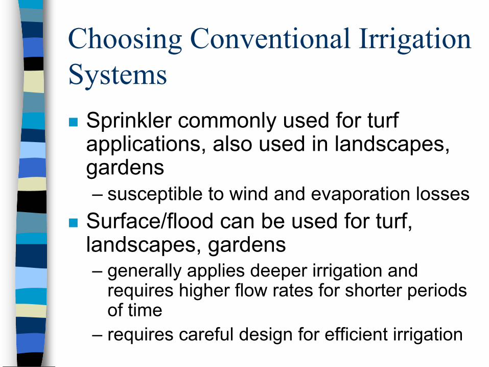
Choosing Conventional Irrigation Systems
Sprinkler commonly used for turf applications, also used in landscapes, gardens– susceptible to wind and evaporation losses
Surface/flood can be used for turf, landscapes, gardens– generally applies deeper irrigation and
requires higher flow rates for shorter periods of time
– requires careful design for efficient irrigation

Conventional Landscape Irrigation Design Process-Rain Bird1. Understand basic hydraulics2. Obtain site information3. Determine irrigation requirements4. Determine water and power supply5. Select sprinklers and spacing ranges6. Lateral layout, circuit sprinklers into valve groups7. Size pipes and valves and calculate system pressure
requirements8. Locate controller and size valve and power wires9. Prepare final irrigation plan

Understanding Basic Hydraulics
Water weighs _________Water is compressible or incompressible?Water exerts pressure or doesn’t exert pressure?If you double the height of the water, the pressure is doubled or tripled or doesn’t change?

Static Water Pressure
Static water pressure = pressure of water with no flow– relates to changes in elevation or pressure
caused by a pump– an indication of the potential pressure
available to operate a systemTo convert pressure in feet to pressure in psi, multiply the feet value by 0.433.
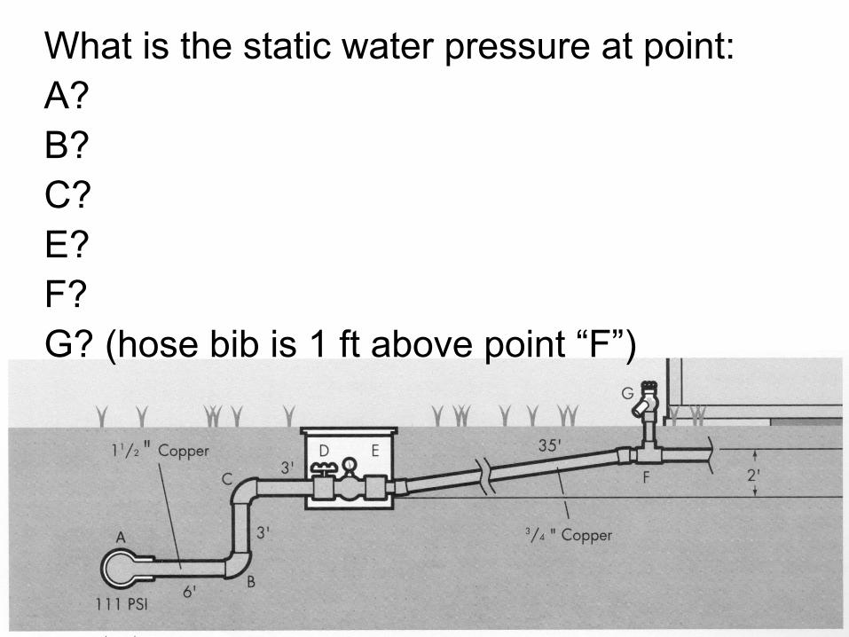
What is the static water pressure at point:A? B? C? E?F?G? (hose bib is 1 ft above point “F”)
Dynamic Water Pressure= water pressure or working pressurepressure of water with water flow– differs from static water pressure due to friction
losses through pipes, fittings, and components of the system
– it is the design pressureamount of water flowing through the components of the system affects the friction loss– more water being forced through the system, the higher the
flow velocity, and higher the water pressure loss.speed that water moves through components affects friction loss– the faster water moves through a pipe, the higher the friction
loss

Dynamic Water Pressure
If water flow is 20 gpm, what is the dynamic water pressure, in psi, at points:B?E?G?

Step 1: Obtaining Site Information
locate all buildings, walkways, driveways, parking areas, light or utility poles, retaining walls, stairwaysindicate slopes, soil type, wind directionindicate no water drift areaslocate all trees, shrubs and pinpoint plant materialsindicate hydraulic data (location of water source, size of water meter & service line, ascertain static water pressure)


Step 2: Determining Irrigation Requirements
Irrigation requirement is measured in:– inches per week– inches per day
Is the amount of water each plant needs less than, equal to, or greater than the amount of water the irrigation system supplies?What two primary factors affect the amount of water needed to satisfy the plant?

Evapotranspiration (ET)
measured in inches per dayET is different for different plants system designed for worst ETET estimated from– mathematical equations– Arizona meteorological data = AZMET
http://ag.arizona.edu/azmet– OR...

Estimating ET - Rain Bird
Climate Inches DailyCool Humid 0.10 –0.15Cool Dry 0.15 – 0.20Warm Humid 0.15 – 0.20Warm Dry 0.20 – 0.25Hot Humid 0.20 – 0.30Hot Dry 0.30 – 0.45

What Affects a Plant’s ET?
Increases ET Decreases ET

Soils
Determine how fast and how often water can be applied to the plant material– soil type and texture
• affects irrigation operational schedule– soil’s intake rate
• dictates how fast water can be applied by the irrigation system
• sprinkler type– need to consider rolling terrain, steep
slopes


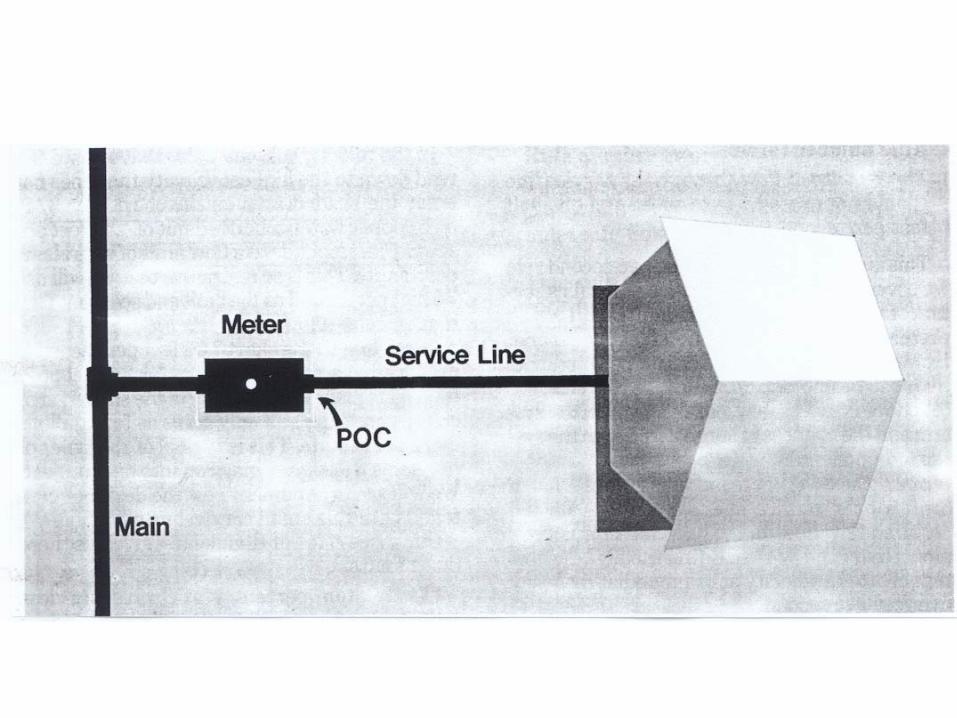
Step 3: Determining Water and Power Supply
Water supply data needed:– flow, gpm, available for irrigation system– working pressure, psi, at the flow above at
the P-O-C– to obtain these, additional data needed:
• static water pressure• water meter size• service line size, length, type

Static water pressure
Determine by either:– direct pressure gauge reading– obtain from water company
Use “worst case” condition (summer, daylight pressure)

Water meter size
usually stamped or cast somewhere on the upper half of meter itselfsometimes printed inside reading lidotherwise, contact your water supplier

Calculating water meter capacity
To calculate the flow, gpm, for irrigation, you will follow 3 rules. Using 3 rules, determine the gpm for each, chose the most restrictive

Rule #1
The pressure loss through the water meter should not exceed 10% of the minimum static water pressure available in the city main.– Prevents heavy pressure loss from
occurring early in the system– example: 3/4” water meter, city water
pressure is 111 psi, what is maximum flow that will produce acceptable loss?
Rule #2
The maximum flow through the meter for irrigation should not exceed 75% of the maximum safe flow of the meter.– Designed to protect water meter from
excess demand– example: 3/4” water meter, what is
maximum safe flow of the meter?

Rule #3
The velocity of flow through the service line should not exceed 5 - 7.5 fps.– Velocities in excess are more likely to
cause damaging surge pressures– metallic pipes commonly used in water
supply systems can withstand higher velocities than thermoplastic pipes in irrigation systems
– example: 3/4” water meter, what are flows associated with 5 and 7.5 fps velocity?
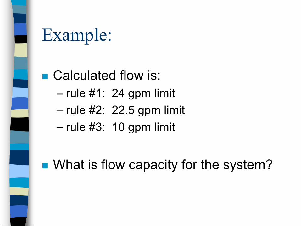
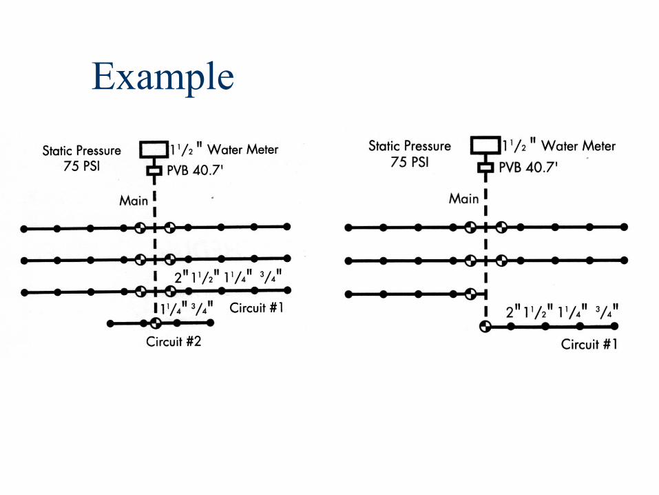
Example:
Calculated flow is:– rule #1: 24 gpm limit– rule #2: 22.5 gpm limit– rule #3: 10 gpm limit
What is flow capacity for the system?

Calculating working pressure
Determine the dynamic water pressure at the P-O-C– from the source to the P-O-C, calculate the
friction losses through all components, take into account any elevation losses or gains, and calculate remaining working pressure.

Step 4: Selecting Sprinklers and Spacing Ranges
Types– spray sprinklers (fixed-head sprinklers)
• shrub sprayheads• pop-up sprayheads
– rotating sprinklers• impulse or impact sprinklers• pop-up gear drive sprinklers
– bubblers and drip irrigation devices• zero-radius or short radius types• ultra-low volume types
Sprinkler Selection
Factors to consider– size and shape of areas to be irrigated– types of plant materials to be irrigated– water pressure and flow available– local environmental conditions
• wind, temperature, precipitation– soil type and rate at which it can accept
water– compatibility of sprinklers to be grouped

Sprinkler - Water Distribution

Sprinkler Spacing
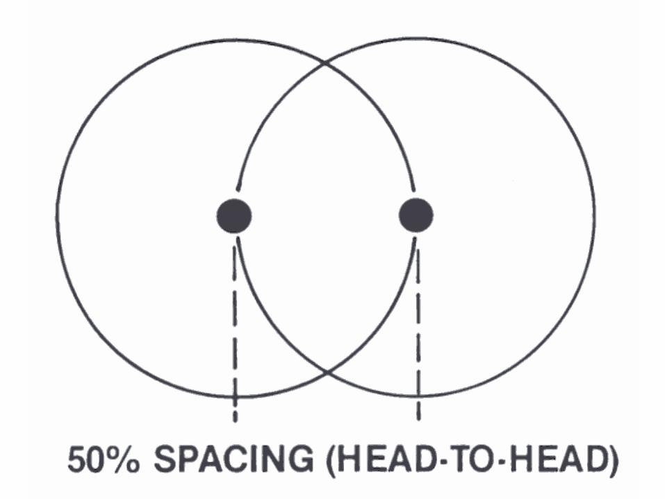
Maximum spacing recommended is 60% of the diameter.In cases where very coarse soil, high winds, low humidity, or high heat inhibit effective irrigation, use head-to-head spacing (50% diameter).
Sprinkler Spacing Patterns
SquareTriangularRectangularSliding

Square pattern

Triangular pattern
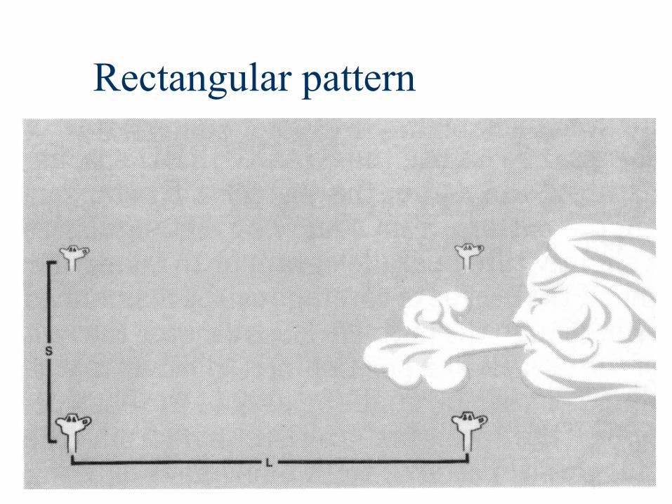
Rectangular pattern

Sliding pattern

Sprinkler Spacing in Windy ConditionsWindVelocity
Max SpacingSquare
Max SpacingTriangle
0 to 3 mph 55% of diam. 60% of diam.
4 to 7 mph 50% of diam. 55% of diam.
8 to 12 mph 45% of diam. 50% of diam.

Precipitation Rate (or how fast you apply the water)
Expressed in inches per hourDetermines if the rate exceeds the soil’s absorption rate.Determines if the rate will apply enough water during water times to meet irrigation requirement.Need to know– total gallons per minute applied by sprinklers– spacing between sprinklers– spacing between rows of sprinklers

Precipitation Rate
PR = 96.3 * GPM (applied to area)S * L
Where:PR = average precipitation rate, in/hrGPM= total gallons per minute applied to
area by sprinklersS = spacing between sprinklersL = spacing between rows of sprinklers
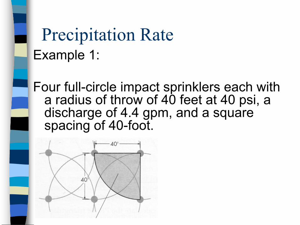
Precipitation Rate Example 1:
Four full-circle impact sprinklers each with a radius of throw of 40 feet at 40 psi, a discharge of 4.4 gpm, and a square spacing of 40-foot.

Precipitation Rate Example 2:
Large-size rotor pop-up sprinklers spaced head-to-head at 70’ in a triangular pattern. The flow from each full-circle sprinkler is 27.9 gpm. What is the PR?

Precipitation Rate Example 2: Solution

Locating Sprinklers on the Plan
Why is this step important?
The goal of sprinkler positioning is to make sure all irrigated areas have adequate sprinkler coverage!!!
Locating Sprinklers on the Plan
Remember:Begin laying out sprinklers in troubled areas first.Wherever possible, use the same type of sprinklers over a given area.After locating all the sprinklers on the plan, visually check entire system for proper spacing and good coverage.
Step 5: Lateral Layout, Circuiting Sprinklers into Valve Groups
Add up the flows of similar sprinklers in each area -- this would be the “valve group”– keep the total flow in each group equal to
or less than the available flow for irrigation calculated in step 3
– consider micro-climate conditions, vegetation heights

Circuit configurations
Straight line lateral circuit
Split-length lateral circuit

Calculating lateral operating time
Why do we need to do this?
How– determine the daily water time (minutes)
each circuit will need to run to satisfy the weekly irrigation needs of the plants

Calculating lateral operating time
OT = I x 60PR x DA
Where:OT = circuit operating time, min/dI = system irrigation requirement, in/wkPR = circuit precipitation rate, in/hrDA = days available for irrigation per week

Example 1
The system irrigation requirement is 1.5 inches per week, you can water 3 days per week, sprinklers put out 3.5 gpm in a full-circle radius of 14 ft, and the sprinkler spacing is 13 x 15 ft rectangular.

Example 2
The system irrigation requirement is 1.5 inches per week, you can water 3 days in the week, sprinklers put out 4.5 gpm in a full-circle radius of 40 ft, and the sprinkler spacing is 40 x 45 ft rectangular.

Step 6: Sizing Pipe and Valves & Calculating System Pressure Requirements
Need to ensure adequate flow and pressure within system to properly operate all sprinklers on the projectUse the 5 fps rule to determine pipe sizing
What was the 5 fps rule, and why was it important?

Sizing Pipe Process
pipe sizing for a sprinkler lateral is done in reversefirst pipe to be sized is the pipe reach supplying the last or furthest sprinkler from the valvecritical circuit length

Example
Each circuit has:4 medium-sized rotor pop-up sprinklers,
that throw 47 ft radius at 55 psi and require 9.8 gpm each.

Example, continued
How big should the main line be?
Sizing Lateral Valves
Guidelinesflow through valve should not produce loss greater than 10% of static water pressure available in main linevalve should either be same size as largest pipe in lateral it serves, or no more than 1 nominal size smaller than pipe.Valve should not be larger than pipes in lateral unless a high flow results from split lateral

Sizing Valves Process
Use guidelinesData needed– static pressure at meter– elevation changes through main– pipe sizes in circuit that each valve serves

Determining the System’s Total Pressure RequirementWHY? -- Simply to determine if the
system will work!!Pr = Ps - (Po + Pls)
Pr = pressure remaining after satisfying total system requirement
Ps = static water pressurePo = operating pressure for “worst case”
sprinklerPls = pressure loss through system main
line and “worst case” lateral circuit
Determining System Total Pressure Requirement Process
Find “worst case” lateralFind “worst case” sprinkler
Example
Step 7: Locating the Controller and Sizing Valve and Power Wires
Locating the controller– locate controller centrally to valve group to
minimize lengths of field wires to valve– locate in pairs or groups to minimize the
length of power supply lines– locate away from direct water spray

Sizing Valve Wires
Always check local electrical codesValve wires usually carry only 24 VAC, are buried (and if buried require UF labeled wire)Higher pressure at valve, more power it takes to raise plunger– therefore, static water pressure important
when sizing valve control wires

Sizing Valve Wire Process
1. Determine actual wire run distance (feet) from the controller to the first valve on a circuit and between each of the other valves on a multiple valve circuit.

Sizing Valve Wire Process
2. Calculate the “equivalent circuit length” for each valve circuit.

Sizing Valve Wire Process
3. From the Rain Bird wire sizing chart, select the common and control wire sizes for the circuit with the highest equivalent circuit length (the “worst case” circuit).
Note: wires should be same size or no more than one sizeapart; larger one is to be usedas the common wire

Sizing Valve Wire Process
4. Having the common wire established, use the wire sizing chart to determine the control wire size for each of the remaining valve circuits on the controller.

Sizing Controller Supply Wires
Factors affecting size of wire– available voltage at power source– distance from the power source to the
controllers– minimum voltage required to operate the
controller– power required by type of valve used– number of valves used on any one station– number of controllers operating at one time

Sizing Controller Supply Wire Process1. Using Rain Bird chart for power wire
sizing, determine the power requirements for the controller selected along with the requirements for the number of solenoid valves that will be operating at one time.
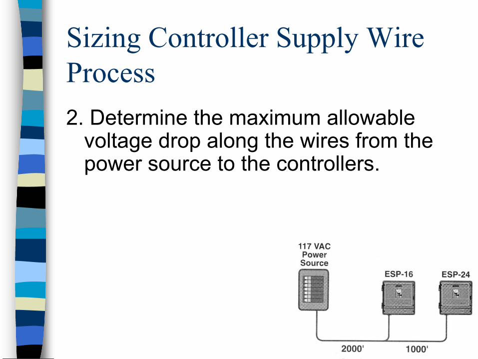
Sizing Controller Supply Wire Process2. Determine the maximum allowable
voltage drop along the wires from the power source to the controllers.

Sizing Controller Supply Wire Process3. Calculate the equivalent circuit length
for the power wire and controller(s).

Sizing Controller Supply Wire Process4. Using the formula below, calculate the
F factor for the circuit.F = allowable voltage drop
amps/control unit x equivalent length
Note: equivalent lengthis in 1000s of feet

Sizing Controller Supply Wire Process5. Select a power wire size from Rain Bird
chart that has an F factor equal to or less than the calculated F factor.

Step 8: Preparing Final Irrigation Plan
Diagram representing what the sprinkler system should look like after installation– be readable, usable, drawn to convenient
scale– contain detailed legend explaining all
symbols used in drawing– show any major elevation changes– show ALL water and power utility locations

Proper design and operation of irrigation systems require ...
experiencescienceart!!!