1 Junji Urakawa (KEK, Japan) at PosiPol2012, 2012.9.06 Under development of Quantum Beam Technology…
Upload
allen-simperCategory
view
217download
0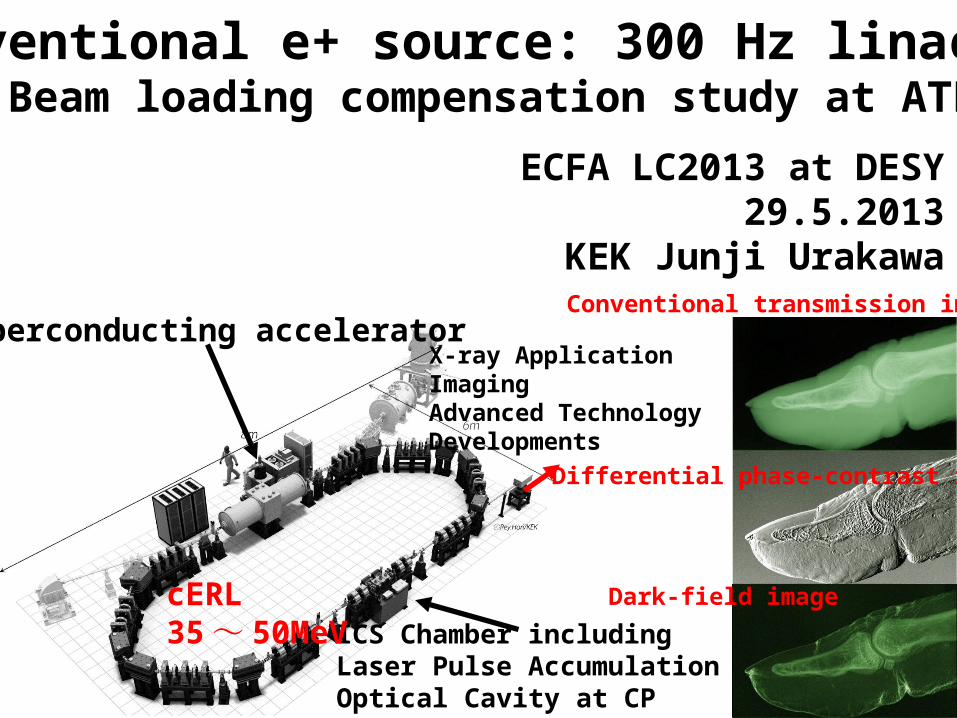
Conventional e+ source: 300 Hz linac R/DBeam loading compensation study at ATF
ECFA LC2013 at DESY29.5.2013
KEK Junji Urakawa
ICS Chamber including Laser Pulse Accumulation Optical Cavity at CP
Superconducting accelerator
cERL35 ~ 50MeV
X-ray ApplicationImagingAdvanced Technology Developments
Conventional transmission image
Differential phase-contrast image
Dark-field image

Time structure of beam0<t<264.45ns, i=0.532A264.45<t<362.85ns, 0A362.85ns<t<627.3ns, 0.532A627.3ns<t<725.7ns, 0A725.7ns<t<990.15ns, 0.532A

Bunch by bunch extraction fromDamping Ringto make ILC beamtrain.
This is the model for positron target systemto confirm the generationof ILC positron beam.
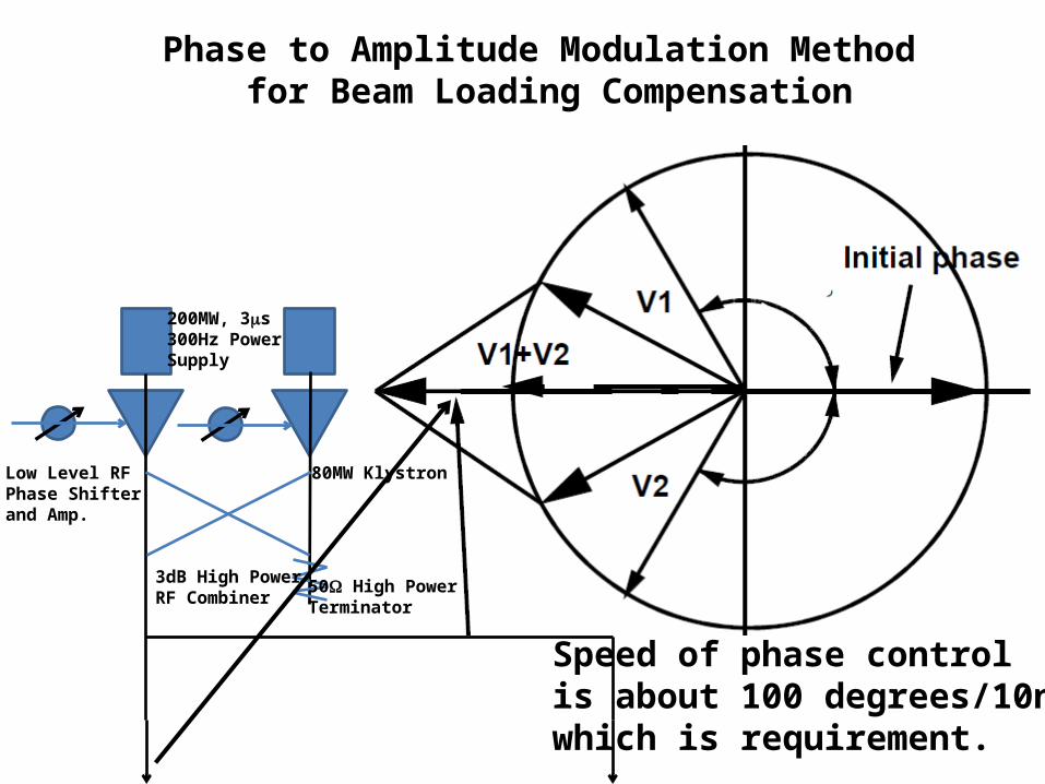
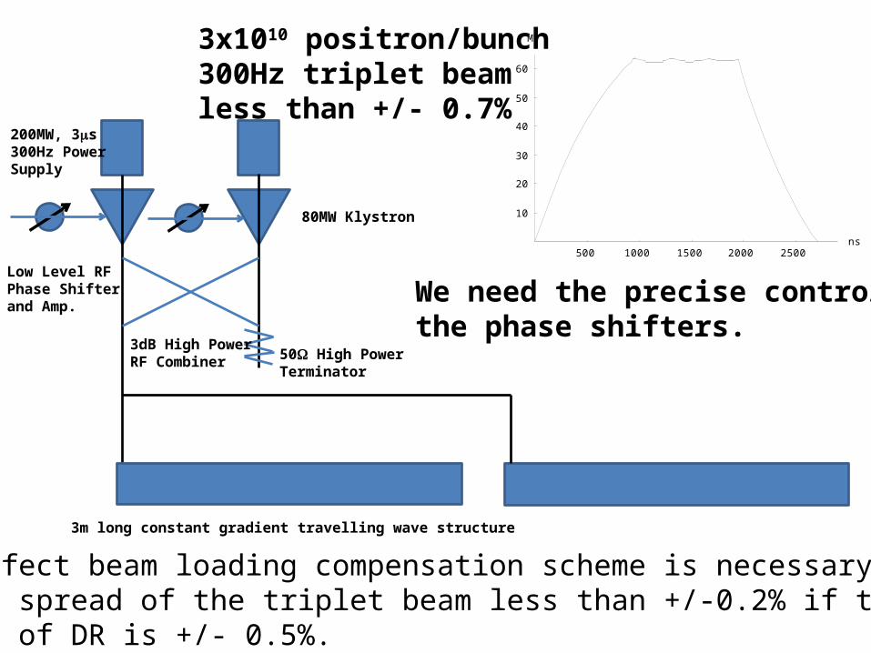
Phase to Amplitude Modulation Method for Beam Loading Compensation
200MW, 3ms300Hz Power Supply
Low Level RFPhase Shifterand Amp.
3dB High PowerRF Combiner
50W High PowerTerminator
80MW Klystron
Speed of phase controlis about 100 degrees/10nswhich is requirement.
200MW, 3ms300Hz Power Supply
Low Level RFPhase Shifterand Amp.
3dB High PowerRF Combiner 50W High Power
Terminator
80MW Klystron
3m long constant gradient travelling wave structure
We need the precise control ofthe phase shifters.
Almost perfect beam loading compensation scheme is necessary to makethe energy spread of the triplet beam less than +/-0.2% if the energy acceptance of DR is +/- 0.5%.
500 1000 1500 2000 2500ns
10
20
30
40
50
60
MV3x1010 positron/bunch300Hz triplet beamless than +/- 0.7%
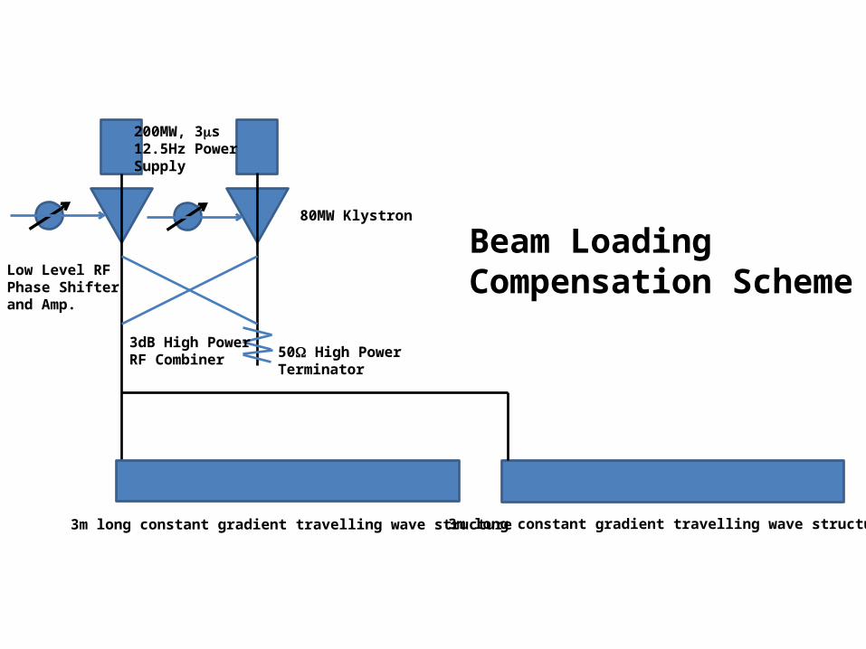
200MW, 3ms12.5Hz Power Supply
Low Level RFPhase Shifterand Amp.
3dB High PowerRF Combiner 50W High Power
Terminator
80MW Klystron
3m long constant gradient travelling wave structure 3m long constant gradient travelling wave structure
Beam Loading Compensation Scheme

3.6 cell RF-Gunstarted beam acceleration test from 1/11,2012.
11MeV beam at 120MV/m, from 100bunches/pulse to 1000bunches/pulse beam generation
0
2
4
6
8
10
0 5 10 15 20 25
3.6 cell RF-Gun
Mom
entu
m [M
eV/c
]
RF Input Power [MW]
y = (m1 * M0)̂ 0.5 エラー値0.141484.4506m1
NA0.56995カイ2乗NA0.92764R
9.6MeV beam ina week RF agingwith ~20.3MW RFinput power
In 2010In 2012
3.6 cell RF Gun Installation
Now, 10MeV multi -bunch trains are generatedand accelerated.
500 1000 1500 2000 2500ns
9.5
10
10.5
11
11.5
12MV
2118 2318 2518 2718ns
9.9
9.92
9.94
9.96
9.98
MVWith RF amplitude modulationAnd without beam
Energy of multi-bunch beam

Phase to Amplitude Modulation Method for Beam Loading Compensation
200MW, 3ms300Hz Power Supply
Low Level RFPhase Shifterand Amp.
3dB High PowerRF Combiner
50W High PowerTerminator
80MW Klystron
Speed of phase controlis about 100 degrees/10ns.

200MW, 3ms300Hz Power Supply
Low Level RFPhase Shifterand Amp.
3dB High PowerRF Combiner 50W High Power
Terminator
80MW Klystron
3m long constant gradient travelling wave structure
We need the precise control ofthe phase shifters.
500 1000 1500 2000 2500ns
10
20
30
40
50
60
70MV
0.9x10¹⁰ electrons/bunchWith 2.8nsec bunch spacingAnd 2856MHz Linac
Almost perfect beam loading compensation scheme is necessary to makethe energy spread of the triplet beam less than +/-0.2% if the energy acceptance of DR is +/- 0.5%.

3.6 cell RF Gun 3m long TW 3m long TW
2x10¹⁰ with 6.15nsec bunch spacing corresponds to 0.9x10¹⁰ in the case of 2.8nsec bunch spacing as same beam loadingin multi-bunch trains.
ATF Triplet Beam : 10 bunches/train with 30nsec train gapand 2.8nsec bunch spacing.
90 degrees bending magnetto measure the energy of multi-bunch
Beam Transport
ATF Injector for 1.3GeV ATF Linac will be modified for beam loading compensation experiment by next year (2014).Due to the lack of 2013 budget, we delayed this experiment.
Chicane for beamDiagnostics and laserinjection
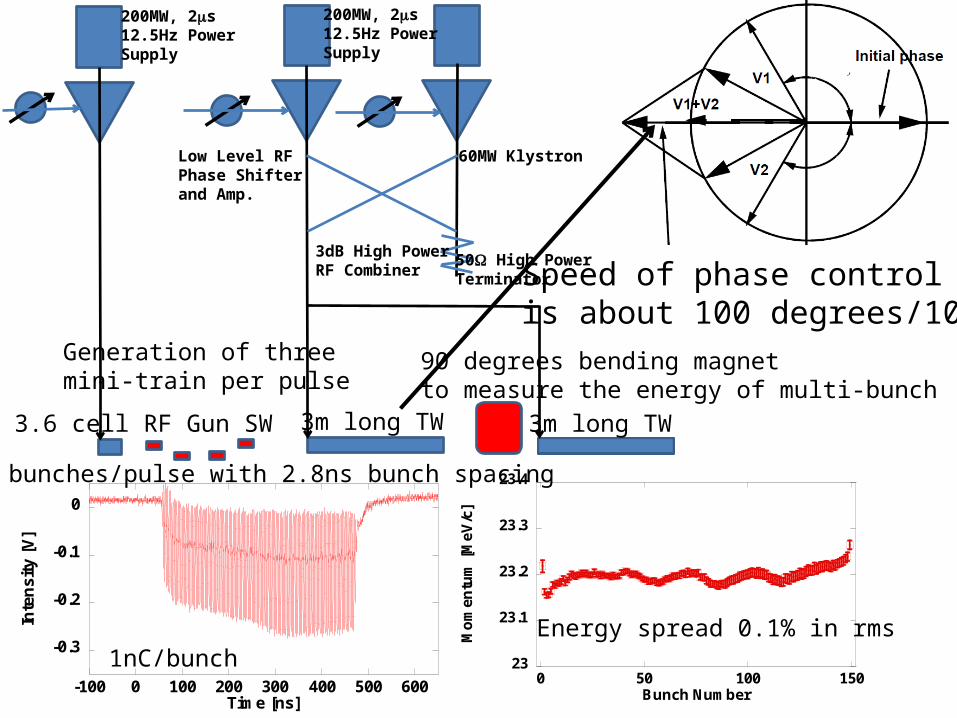
3.6 cell RF Gun SW 3m long TW 3m long TW
90 degrees bending magnetto measure the energy of multi-bunch
200MW, 2ms12.5Hz Power Supply
Low Level RFPhase Shifterand Amp.
3dB High PowerRF Combiner
50W High PowerTerminator
60MW Klystron
Speed of phase controlis about 100 degrees/10ns.
23
23.1
23.2
23.3
23.4
0 50 100 150
Mo
men
tum
[M
eV/c
]
Bunch Number
-0.3
-0.2
-0.1
0
-100 0 100 200 300 400 500 600
Inte
nsi
ty [
V]
Time [ns]
Energy spread 0.1% in rms
150 bunches/pulse with 2.8ns bunch spacing
Generation of threemini-train per pulse
200MW, 2ms12.5Hz Power Supply
1nC/bunch

From NIM A 560 (2006) 233–239.
S-band RF Gun, more than 100MV/mOperation:120MV/m,max.:140MV/m
250mm
1.6 cell RFGun alreadyDemonstratedMulti-bunchBeam loadingCompensation.

200MW, 3ms300Hz Power Supply
Low Level RFPhase Shifterand Amp.
3dB High PowerRF Combiner 50W High Power
Terminator
80MW Klystron
A0 3m long constant gradient travelling wave structure
We need the precise control ofthe phase shifters.
500 1000 1500 2000 2500ns
10
20
30
40
50
60
70MV
0.9x10¹⁰ electrons/bunchWith 2.8nsec bunch spacingand 2856MHz Linac
3.6 cell RF Gun
High power att.
Almost perfect beam loading compensation scheme is necessary to makethe energy spread of the triplet beam less than +/-0.2% if the energy acceptance of DR is +/- 0.5%.
Speed of RF amplitude controlis essential to make the perfectbeam loading compensation.
less than +/-0.2%control is possible.
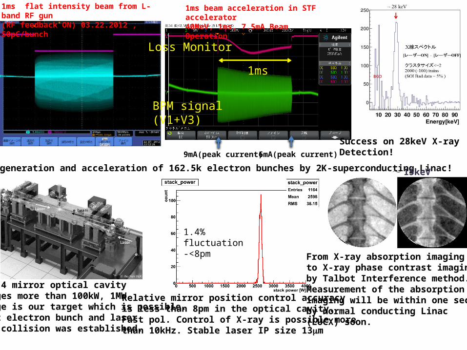
1ms flat intensity beam from L-band RF gun(RF feedback ON) 03.22.2012 , 50pC/bunch
9mA(peak current) 6mA(peak current)
Loss Monitor
BPM signal(V1+V3)
1ms
1ms beam acceleration in STF accelerator40MeV, 1ms, 7.5mA Beam Operation
Success on generation and acceleration of 162.5k electron bunches by 2K-superconducting Linac!
2m 2D-4 mirror optical cavitystorages more than 100kW, 1MW storage is our target which is possible. 375MHz electron bunch and laser pulse collision was established.
1.4% fluctuation-<8pm
Relative mirror position control accuracy is less than 8pm in the optical cavity.Fast pol. Control of X-ray is possible morethan 10kHz. Stable laser IP size 13mm
~ 15keV
From X-ray absorption imagingto X-ray phase contrast imagingby Talbot Interference method.Measurement of the absorption imaging will be within one second by normal conducting Linac (LUCX) soon.
Success on 28keV X-ray Detection!
15
X-ray Detector
Beam Dump RF Gun Laser
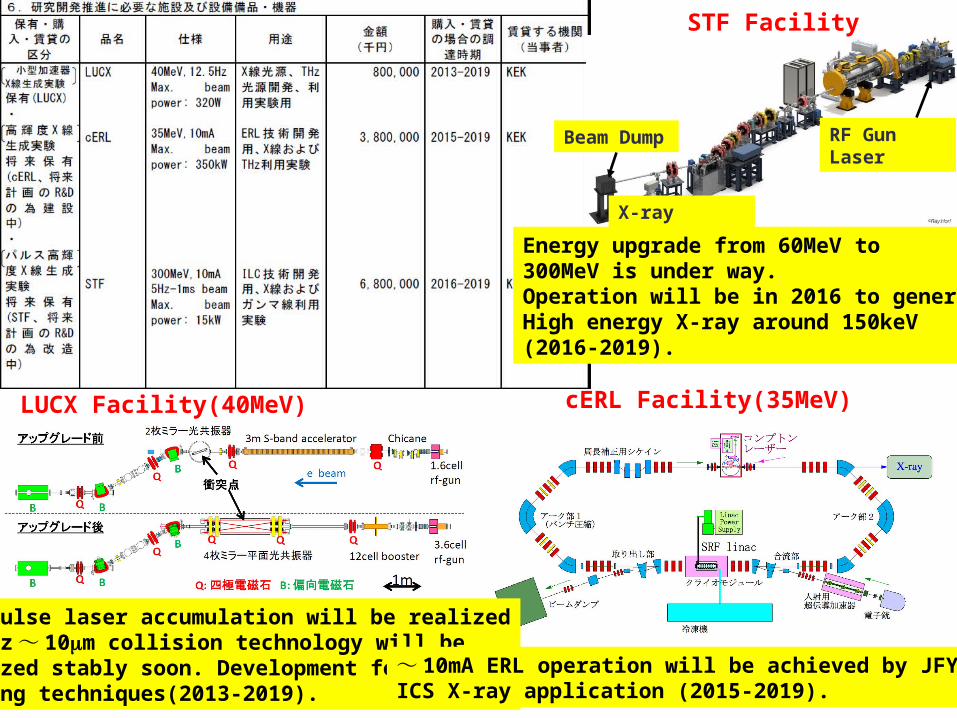
STF Facility
Energy upgrade from 60MeV to 300MeV is under way.Operation will be in 2016 to generate High energy X-ray around 150keV(2016-2019).
LUCX Facility(40MeV)
1MW pulse laser accumulation will be realized357MHz ~ 10mm collision technology will beRealized stably soon. Development for X-ray imaging techniques(2013-2019).
cERL Facility(35MeV)
~ 10mA ERL operation will be achieved by JFY2015ICS X-ray application (2015-2019).

16
研究組織、責任体制
代表機関高エネルギー加速器研究機構
超伝導高周波加速器開発装置の構築・運転、性能測定ポスドク・大学院生教育
提供施設: LUCX, STF, cERL開発打合せ、運営会議の開催
協力機関東芝電子管デバイス
小型高周波源開発
協力機関東京大学
高強度耐性高反射率ミラー開発
大学院生教育破壊試験
参画機関
原機構 (JAEA)4k 超伝導 spoke 空洞開
発cERL 電子源試験装置500kV 電子銃運転
協力機関日立製作所 小型冷凍機開発
参画機関
広島大学レーザー蓄積装置開発
高周波電子源開発、カソード開発大学院生教育
施設の供用:カソード試験装置
参画機関
早稲田大学レーザー開発、
レーザー・電子衝突実験大学院生教育
施設の供用:小型加速器
研究開発運営委員会構成委員:参画メンバー+外部委
員
マルチビームクライストロンの小型化・高安定化
可視光励起の高量子効率カソード開発
両ビームの品質を向上して、良質のX 線発生・検出
カソード・ 電子銃開
発
高周波源開発
参画機関日本大学
20kクライオ高周波電子銃大学院生教育
協力機関大阪大学(産研)電子源利用・運転協力大学院生教育
施設の供用:線型加速器
参画機関(株)リガク
X-ray イメージング装置開発
参画機関東北大学
X線イメージング法開発
干渉イメージング装置協力機関
国立天文台(重力波測定グループ)
高強度耐性高反射率ミラー開発
レーザー開発
参画機関
産総研 (AIST)X-ray 利用
レーザー開発
ミラー開発
イメージング装置開発
参画機関京都大学
4k超伝導 spoke空洞
大学院生教育
17
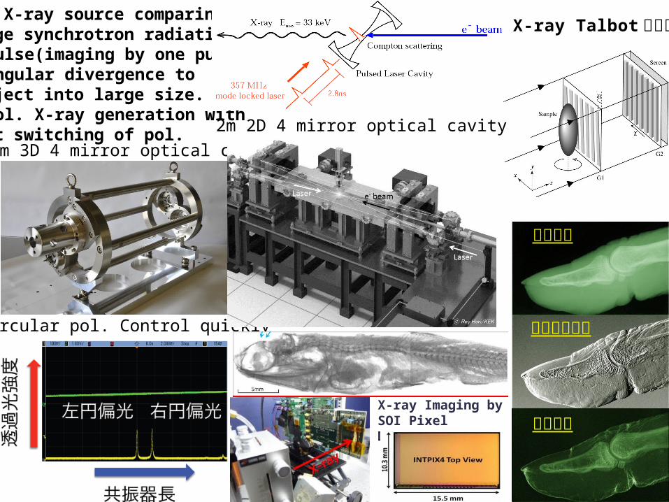
ICS X-ray source comparing large synchrotron radiation.・ pulse(imaging by one pulse)・ angular divergence to project into large size.・ pol. X-ray generation withfast switching of pol.
吸収画像
微分位相画像
散乱画像
X-ray Talbot 干渉計
0.42m 3D 4 mirror optical cavity
Circular pol. Control quickly
X-ray Imaging by SOI Pixel Detector
2m 2D 4 mirror optical cavity
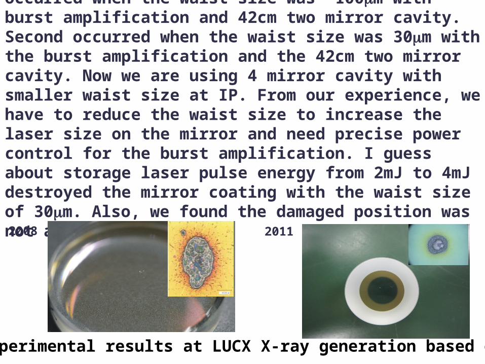
We destroyed the mirror coating two times. First occurred when the waist size was ~100mm with burst amplification and 42cm two mirror cavity. Second occurred when the waist size was 30mm with the burst amplification and the 42cm two mirror cavity. Now we are using 4 mirror cavity with smaller waist size at IP. From our experience, we have to reduce the waist size to increase the laser size on the mirror and need precise power control for the burst amplification. I guess about storage laser pulse energy from 2mJ to 4mJ destroyed the mirror coating with the waist size of 30mm. Also, we found the damaged position was not at the center.
2008 2011
From experimental results at LUCX X-ray generation based on ICS.
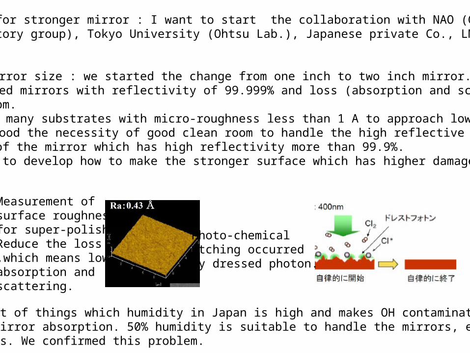
Development for stronger mirror : I want to start the collaboration with NAO (Gravitational Wave Observatory group), Tokyo University (Ohtsu Lab.), Japanese private Co., LMA and LAL hopefully.
1. Enlarge mirror size : we started the change from one inch to two inch mirror.2. LMA prepared mirrors with reflectivity of 99.999% and loss (absorption and scattering)less than 6ppm.3. We ordered many substrates with micro-roughness less than 1 A to approach low loss mirror.4. We understood the necessity of good clean room to handle the high reflective mirrorsin the case of the mirror which has high reflectivity more than 99.9%.5. We have to develop how to make the stronger surface which has higher damage threshold.
Photo-chemical etching occurred by dressed photon.
Measurement of surface roughnessfor super-polish.Reduce the loss,which means lowabsorption andscattering.
We learnt a lot of things which humidity in Japan is high and makes OH contamination to increase the mirror absorption. 50% humidity is suitable to handle the mirrors, especially high quality mirrors. We confirmed this problem.
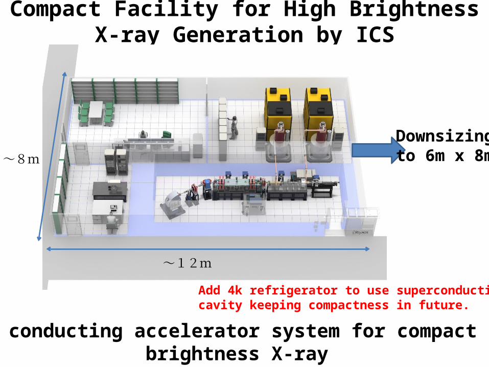
Compact Facility for High Brightness X-ray Generation by ICS
~12m
~8m
Normal conducting accelerator system for compact high brightness X-ray
Add 4k refrigerator to use superconductingcavity keeping compactness in future.
Downsizingto 6m x 8m