Controls – Contactors and Contactor Assemblies€¦ · Controls — Contactors and Contactor...
25
Siemens LV 1 · 2008 3/2 Introduction 3RT, 3TB, 3TF Contactors for Switching Motors 3/5 General data 3/11 3RT10 contactors, 3-pole, 3 ... 250 kW 3/26 3RT12 vacuum contactors, 3-pole, 110 ... 250 kW 3/27 3TF6 vacuum contactors, 3-pole, 335 ... 450 kW 3/29 3TB5 contactors with DC solenoid system, 3-pole, 55 ... 200 kW 3/30 3TF2 contactors, 3-pole, 2.2 ... 4 kW 3RA13, 3RA14 Contactor Assemblies 3RA13 Reversing Contactor Assemblies 3/32 3RA13 complete units, 3 ... 45 kW 3/37 Components for customer assembly 3RA14 Contactor Assemblies for Wye-Delta Starting 3/40 3RA14 complete units, 3 ...75 kW 3/47 Components for customer assembly 3TD, 3TE Contactor Assemblies 3/48 3TD6 reversing contactor assemblies, 335 kW 3/49 3TE6 contactor assemblies for wye-delta starting, 630 kW 3RT, 3RH, 3TB, 3TC, 3TH, 3TK Contactors for Special Applications 3RT14 Contactors for Switching Resistive Loads (AC-1) 3/50 3-pole, 140 ... 690 A 3RT13 Contactors for Switching Resistive Loads (AC-1) 3/52 4-pole, 4 NO, 18 ... 140 A 3TK1 Contactors for Switching Resistive Loads (AC-1) 3/54 4-pole, 4 NO, 200 ... 1000 A 3TK20 Contactors 3/55 4-pole, 4 kW 3RT15 Contactors 3/57 4-pole, 2 NO + 2 NC, 4 ... 18.5 kW 3RT16 Capacitor Contactors 3/58 12.5 ... 50 kvar Contactors with Extended Operating Range 0.7 ... 1.25 × U s , for Railway Applications 3/59 3RH11 contactor relays 3/60 3TH4 contactor relays 3/61 3RT10 motor contactors, 5.5 ... 45 kW 3/64 3TB5 motor contactors, 55 ... 200 kW 3/65 3TC contactors for switching DC voltage, 2-pole 3TC Contactors for Switching DC Voltage 3/66 1- and 2-pole, 32 ... 400 A 3RH, 3TH Contactor Relays 3/69 3RH1 contactor relays, 4- and 8-pole 3/72 3RH14 latched contactor relays, 4-pole 3/73 3TH4 contactor relays, 8- and 10-pole 3/75 3TH2 contactor relays, 4- and 8-pole 3/78 3RH11 coupling relays for switching auxiliary circuits, 4-pole 3RT Coupling Relays 3/79 3RT10 coupling relays (interface), for switching motors, 3-pole, 3 ... 11 kW 3TX7, 3RS18 Coupling Relays 3TX7 Coupling Relays, Narrow Design 3/82 Relay couplers 3/84 Relay couplers with plug-in connection 3/86 Semiconductor couplers 3RS18 Coupling Relays with Industrial Housing 3/88 Relay couplers LZS, LZX Plug-In Relays 3/89 Relay couplers 3TG10 Power Relays/Miniature Contactors 3/96 4-pole, 4 kW Accessories and Spare Parts For 3RT, 3RH Contactors and Contactor Relays 3/97 Accessories for 3RT, 3RH contactors and contactor relays 3/114 Spare parts for 3RT, 3RH contactors and contactor relays For 3T Contactors and Contactor Relays 3/119 Accessories for 3TB, 3TC, 3TF, 3TG, 3TK contactors 3/124 Accessories for 3TH contactor relays 3/127 Spare parts for 3TB, 3TC, 3TF, 3TK contactors Note: For safety characteristics for contactors see "Appendix" --> "Standards and Approvals" --> "Overview" Controls – Contactors and Contactor Assemblies © Siemens AG 2008
-
Upload
truongkiet -
Category
Documents
-
view
238 -
download
0
Transcript of Controls – Contactors and Contactor Assemblies€¦ · Controls — Contactors and Contactor...

Siemens LV 1 · 2008
3/2 Introduction
3RT, 3TB, 3TF Contactors for Switching Motors
3/5 General data3/11 3RT10 contactors, 3-pole, 3 ... 250 kW3/26 3RT12 vacuum contactors, 3-pole,
110 ... 250 kW3/27 3TF6 vacuum contactors, 3-pole,
335 ... 450 kW3/29 3TB5 contactors with DC solenoid system,
3-pole, 55 ... 200 kW3/30 3TF2 contactors, 3-pole, 2.2 ... 4 kW
3RA13, 3RA14 Contactor Assemblies3RA13 Reversing Contactor Assemblies
3/32 3RA13 complete units, 3 ... 45 kW3/37 Components for customer assembly
3RA14 Contactor Assemblies forWye-Delta Starting
3/40 3RA14 complete units, 3 ...75 kW3/47 Components for customer assembly
3TD, 3TE Contactor Assemblies3/48 3TD6 reversing contactor assemblies,
335 kW3/49 3TE6 contactor assemblies for wye-delta
starting, 630 kW
3RT, 3RH, 3TB, 3TC, 3TH, 3TK Contactors for Special Applications3RT14 Contactors for Switching ResistiveLoads (AC-1)
3/50 3-pole, 140 ... 690 A3RT13 Contactors for Switching ResistiveLoads (AC-1)
3/52 4-pole, 4 NO, 18 ... 140 A3TK1 Contactors for Switching ResistiveLoads (AC-1)
3/54 4-pole, 4 NO, 200 ... 1000 A3TK20 Contactors
3/55 4-pole, 4 kW3RT15 Contactors
3/57 4-pole, 2 NO + 2 NC, 4 ... 18.5 kW3RT16 Capacitor Contactors
3/58 12.5 ... 50 kvarContactors with ExtendedOperating Range 0.7 ... 1.25 × Us,for Railway Applications
3/59 3RH11 contactor relays3/60 3TH4 contactor relays3/61 3RT10 motor contactors, 5.5 ... 45 kW3/64 3TB5 motor contactors, 55 ... 200 kW3/65 3TC contactors for switching
DC voltage, 2-pole3TC Contactors for Switching DC Voltage
3/66 1- and 2-pole, 32 ... 400 A
3RH, 3TH Contactor Relays3/69 3RH1 contactor relays, 4- and 8-pole3/72 3RH14 latched contactor relays, 4-pole3/73 3TH4 contactor relays, 8- and 10-pole3/75 3TH2 contactor relays, 4- and 8-pole3/78 3RH11 coupling relays for switching
auxiliary circuits, 4-pole
3RT Coupling Relays3/79 3RT10 coupling relays (interface),
for switching motors, 3-pole, 3 ... 11 kW
3TX7, 3RS18 Coupling Relays
3TX7 Coupling Relays, Narrow Design3/82 Relay couplers3/84 Relay couplers with plug-in connection3/86 Semiconductor couplers
3RS18 Coupling Relays withIndustrial Housing
3/88 Relay couplers
LZS, LZX Plug-In Relays3/89 Relay couplers
3TG10 Power Relays/Miniature Contactors
3/96 4-pole, 4 kW
Accessories and Spare Parts
For 3RT, 3RH Contactors andContactor Relays
3/97 Accessories for 3RT, 3RH contactors and contactor relays
3/114 Spare parts for 3RT, 3RH contactors and contactor relays
For 3T Contactors and Contactor Relays3/119 Accessories for 3TB, 3TC, 3TF,
3TG, 3TK contactors3/124 Accessories for 3TH contactor relays3/127 Spare parts for 3TB, 3TC,
3TF, 3TK contactors
Note:For safety characteristics for contactors see "Appendix" --> "Standards and Approvals" --> "Overview"
Controls –Contactors and Contactor Assemblies
© Siemens AG 2008

Controls — Contactors and Contactor Assemblies
Introduction
3/2 Siemens LV 1 · 2008
3
n Overview
SizeType
S003RT10 1
S03RT10 2
S23RT10 3
3RT10 contactors · 3RT12 and 3TF68/69 vacuum contactorsType 3RT10 15 3RT10 16 3RT10 17 3RT10 23 3RT10 24 3RT10 25 3RT10 26 3RT10 34 3RT10 35 3RT10 36AC, DC operation (p. 3/15, 3/19) (p. 3/16, 3/20) (p. 3/17, 3/21)Type -- -- --
AC-3
Ie/AC-3/400 V A 7 9 12 9 12 17 25 32 40 50400 V kW 3 4 5.5 4 5.5 7.5 11 15 18.5 22
230 V500 V690 V
1 000 V3RT10/123RT10/12
kWkWkWkW
2.23.54
--
34.55.5
--
35.55.5
--
34.55.5
--
37.57.5
--
41011--
5.51111--
7.518.518.5--
112222--
153022--
AC-4 (for Ia = 6 x Ie)
400 V400 V 3RT10/12
kWkW
31.15
42
42
42
5.52.6
7.53.5
7.54.4
158.2
18.59.5
2212.6
(200 000 operating cycles)AC-1 (40 °C, ≤ 690 V)
Ie 3RT10/12 A 18 22 22 40 40 40 40 50 60 60
3RT14 AC-1 contactorsType -- -- --
Ie/AC-1/40 °C/≤ 690 V A -- -- --
Accessories for contactorsAuxiliary switch blocks front
lateral3RH19 11--
(p. 3/100) 3RH19 213RH19 21
(p. 3/100)(p. 3/103)
Terminal covers -- -- 3RT19 36-4EA2 (p. 3/112)Box terminal blocks -- -- --
Surge suppressors 3RT19 16 (p. 3/107) 3RT19 26 (p. 3/107) 3RT19 26/36 (p. 3/107)
3RU1 and 3RB2 overload relays (protection equipment: overload relays)3RU11, thermal, CLASS 10 3RU11 16 0.1 ... 12 A (Chap. 5) 3RU11 26 1.8 ... 25 A (Chap. 5) 3RU11 36 5.5 ... 50 A (Chap. 5)3RB20/21, solid-state, CLASS 5, 10, 20 and 30
3RB20 163RB21 16
0.1 ... 12 A (Chap. 5) 3RB20 263RB21 26
3 ... 25 A (Chap. 5) 3RB20 363RB21 36
6 ... 50 A (Chap. 5)
3RB22/23, solid-state, CLASS 5, 10, 20 and 30
3RB2. 83 + 3RB29 06 3RB2. 83 + 3RB29 060.3 ... 25 A (Chap. 5) 10 ... 100 A (Chap. 5)
3RV10 motor starter protectors (protection equipment: motor starter protectors)Type 3RV10 11 0.18 ... 12 A (Chap. 5) 3RV10 21 9 ... 25 A (Chap. 5) 3RV10 31 22 ... 50 A (Chap. 5)Link modules 3RA19 11 (Chap. 5) 3RA19 21 (Chap. 5) 3RA19 31 (Chap. 5)
3RA13 reversing contactor assembliesComplete units Type 3RA13 15
(p. 3/33)3RA13 16 3RA13 17 3RA13 24
(p. 3/34)3RA13 25 3RA13 26 3RA13 34
(p. 3/35)3RA13 35 3RA13 36
400 V kW 3 4 5.5 5.5 7.5 11 15 18.5 22
Installation kits/wiring modules 3RA19 13-2A (p. 3/38) 3RA19 23-2A (p. 3/38) 3RA19 33-2A (p. 3/38)Mechanical interlocks 3RA19 12-2H (p. 3/39) 3RA19 24-1A/-2B (p. 3/37)
3RA14 contactor assemblies for wye-delta startingComplete units Type 3RA14 15
(p. 3/42)3RA14 16 3RA14 23
(p. 3/43)3RA14 25 3RA14 34
(p. 3/44)3RA14 35(p. 3/45)
3RA14 36
400 V kW 5.5 7.5 11 15/18.5 22/30 37 45
Installation kits/wiring modules 3RA19 13-2B (p. 3/47) 3RA19 23-2B (p. 3/47) 3RA19 33-2B/-2C (p. 3/47)
© Siemens AG 2008

Controls — Contactors and Contactor Assemblies
Introduction
3/3Siemens LV 1 · 2008
3
S33RT1. 4
S63RT1. 5
S103RT1. 6
S123RT1. 7
143TF6
3RT10 44 3RT10 45 3RT10 46 3RT10 54 3RT10 55 3RT10 56 3RT10 64 3RT10 65 3RT10 66 3RT10 75 3RT10 76 --(p. 3/18, 3/21) (p. 3/22) (p. 3/22) (p. 3/22)-- -- 3RT12 64
(p. 3/26)3RT12 65 3RT12 66 3RT12 75
(p. 3/26)3RT12 76 3TF68
(p. 3/27)3TF69
65 80 95 115 150 185 225 265 300 400 500 630 82030 37 45 55 75 90 110 132 160 200 250 335 450
18.5374530
22455537
22555537
3775
11075
4590
13290
5511016090
5516020090/315
75160250132/355
90200250132/400
132250400250/560
160355400/500250/710
200434600600
260600800800
3015.1
3717.9
4522
5529
7538
9045
11054/78
13266/93
16071/112
20084/140
25098/161
355168
400191
100 120 120 160 185 215 275/330 330 330 430/610 610 700 910
3RT14 46 (p. 3/50) 3RT14 56 (p. 3/51) 3RT14 66 (p. 3/51) 3RT14 76 (p. 3/51) --
140 275 400 690 --
--3TY7 561 (p. 3/120)
3RT19 46-4EA1/2 (p. 3/112) 3RT19 56-4EA1/2/3 (p. 3/112) 3RT19 66-4EA1/2/3 (p. 3/112) 3TX7 686/696 (p. 3/120)-- 3RT19 55/56-4G (p. 3/112) 3RT19 66-4G (p. 3/112) --
3RT19 56-1C (RC element) (p. 3/108) 3TX7 572 (p. 3/119)
3RU11 46 18 ... 100 A (Chap. 5) -- -- -- --
3RB20 463RB21 46
12.5 ... 100 A (Chap. 5) 3RB20 563RB21 56
50 ... 200 A (Chap. 5) 3RB20 663RB21 66
55 ... 630 A (Chap. 5)
3RB20 663RB21 66
160 ... 630 A (Chap. 5)
3RB20 663RB21 66
160 ... 630 A (Chap. 5)
3RB2. 83 + 3RB29 56 3RB2. 83 + 3RB29 6620 ... 200 A (Chap. 5) 63 ... 630 A (Chap. 5)
3RV10 41 45 ... 100 A (Chap. 5) -- -- -- --
3RA19 41 (Chap. 5) -- -- -- --
3RA13 44(p. 3/36)
3RA13 45 3RA13 46 -- -- -- 3TD68 04(p. 3/48)
30 37 45 55 75 90 110 132 160 200 250 335
3RA19 43-2A (p. 3/38) 3RA19 53-2A (p. 3/38) 3RA19 63-2A (p. 3/38) 3RA19 73-2A (p. 3/38) 3TX7 680-1A
3RA19 54-2A (p. 3/37) 3TX7 686-1A
3RA14 44(p. 3/46)
3RA14 45 -- -- -- 3TE68 04(p. 3/49)
55 75 -- -- -- 630
3RA19 43-2B/-2C (p. 3/47) 3RA19 53-2B (p. 3/47) 3RA19 63-2B (p. 3/47) 3RA19 73-2B (p. 3/47) 3TX7 680-1B
© Siemens AG 2008

Controls — Contactors and Contactor Assemblies
Introduction
3/4 Siemens LV 1 · 2008
3
Connection methods
The contactors and relays are available with screw terminals (box terminals and connecting bars) or with Cage Clamp terminalsor spring-loaded terminals. Some device types are also available with plug-type connectors.
The advantages at a glance
Order No. PageCoupling links, narrow designRelay couplers • Width 6.2 mm (1 NO, 1 CO), 12.5 mm and 17.5 mm
• Output coupling links• Input coupling links with hard gold-plating
3TX7 002, 3TX7 003, 3TX7 004, 3TX7 005
3/82
Plug-in base couplers, complete with relay • Width 6.2 mm (1 NO, 1 CO)• Relays, replaceable
3TX7 014-1..00 3/84
Plug-in base couplers, complete with relay and hard gold-plating
• Width 6.2 mm (1 CO) 3TX7 014-1..02 3/84
Semiconductor couplers • Output 1 semiconductor, triac or transistor 3TX7 002, 3TX7 004, 3TX7 005
3/86
Coupling relays in industrial housingRelay couplers • Safe isolation up to 300 V between contacts and relay circuits
• 1, 2 and 3 changeover contacts• Hard gold-plated contacts in combination and wide voltage
range versions
3RS18 3/88
Plug-in relaysRelay couplers with 2, 3 and 4 changeover contacts • Switching capacity 12 A/10 A/6 A
• Width 27 mm• Base optionally with or without logical isolation
LZS/LZX:PT 3/90
Relay couplers with 3 changeover contacts and circular base
• Switching capacity 6 A• 11-pole circular base• Width 38 mm
LZS/LZX:MT 3/92
Relay couplers with 1, 2 changeover contacts • Switching capacity 16 A/8 A• Width 15.5 mm• Base optionally with or without logical isolation
LZS/LZX:RT 3/93
Power relaysWith screw and flat connectors 3TG10 3/96
3TX7 3RS18 LZS/LZX 3TG10
The devices with screw terminals are indicated in the selectionand ordering data by green backgrounds.
The devices with Cage Clamp terminals or with spring-loadedterminals are indicated in the selection and ordering data by orange backgrounds.
The devices with plug-type connectors are indicated in the selection and ordering data by blue backgrounds.
© Siemens AG 2008

3RT, 3TB, 3TF Contactors for Switching Motors
General data
3/5Siemens LV 1 · 2008
3
n Overview
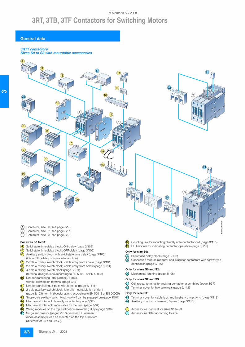
3RT1 contactors and coupling relaysSize S00 with mountable accessories
For contactor assemblies see pages 3/32 to 3/39. For installation kit for reversing contactor assemblies (mech. interlocking, wiring modules) see page 3/38. For mountable overload relays see Pro-tection Equipment: Overload Relays. For fuseless load feeders, see Load Feeders, Motor Starters and Soft Starters -> 3RA Fuseless Load Feeders
The SIRIUS generation of controls is a complete, modular system family, logically designed right down to the last detail, from the basic units to the accessories.
Contactor (page 3/15)Coupling relay (page 3/79)
Solid-state time-delay block, ON-delay (page 3/106)Solid-state time-delay block, OFF-delay (page 3/106)Auxiliary switch block with solid-state time delay (page 3/105) (ON or OFF-delay or wye-delta function)1-pole auxiliary switch block, cable entry from above (page 3/100)2-pole auxiliary switch block, cable entry from above (page 3/100)1-pole auxiliary switch block, cable entry from below (page 3/100)2-pole auxiliary switch block, cable entry from below (page 3/100)4-pole auxiliary switch block (page 3/100) (terminal designations accordingto EN 50012 or EN 50005)2-pole auxiliary switch block, standard version or solid-state time-delay version (pages 3/100, 3/105) (terminal designations according to EN 50005)Solder pin adapter for contactors with 4-pole auxiliary switch block (page 3/111)Solder pin adapter for contactors and coupling relays (page 3/110)
Additional load module for increasing the permissible residual current (page 3/109)Surge suppressor with LED (page 3/108)Surge suppressor without LED (page 3/108)3-phase feeder terminal (page 3/47)Link for paralleling (star jumper), 3-pole, without terminal (page 3/47)Link for paralleling, 3-pole, with terminal (page 3/111)Link for paralleling, 4-pole, with terminal (page 3/111)Connection module (adapter and plug) for contactors with screw-type connection (page 3/110)
For contactorsFor contactors and coupling relays (interface)
NSB0_00448a
15
3
4
5
6
7
8
9
10
11
14
2019
16
12
13
1
17
18
2
21
12
345
678910
11
12
13
14
15161718
192021
© Siemens AG 2008
3RT, 3TB, 3TF Contactors for Switching Motors
General data
3/6 Siemens LV 1 · 2008
3
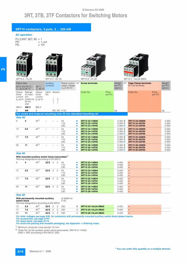
3RT1 contactorsSizes S0 to S3 with mountable accessories
NSB0_00449b
4
10
5
1817
16
11
1
12
96
15
14
1
8
7
13
16
19
22
21
2
20
26
22
23
24
3
21
25
Contactor, size S0, see page 3/16Contactor, size S2, see page 3/17Contactor, size S3, see page 3/18
123
For sizes S0 to S3:
Solid-state time-delay block, ON-delay (page 3/106)Solid-state time-delay block, OFF-delay (page 3/106)Auxiliary switch block with solid-state time delay (page 3/105) (ON or OFF-delay or wye-delta function)2-pole auxiliary switch block, cable entry from above (page 3/101)2-pole auxiliary switch block, cable entry from below (page 3/101)4-pole auxiliary switch block (page 3/101)(terminal designations according to EN 50012 or EN 50005)Link for paralleling (star jumper), 3-pole, without connection terminal (page 3/47)Link for paralleling, 3-pole, with terminal (page 3/111)2-pole auxiliary switch block, laterally mountable left or right (page 3/103) (terminal designations according to EN 50012 or EN 50005)Single-pole auxiliary switch block (up to 4 can be snapped on) (page 3/101)Mechanical interlock, laterally mountable (page 3/37)Mechanical interlock, mountable on the front (page 3/37)Wiring modules on the top and bottom (reversing duty) (page 3/39)Surge suppressor (page 3/107) (varistor, RC element, diode assembly), can be mounted on the top or bottom (different for S0 and S2/S3)
Coupling link for mounting directly onto contactor coil (page 3/110)LED module for indicating contactor operation (page 3/110)
Only for size S0:
Pneumatic delay block (page 3/106)Connection module (adapter and plug) for contactors with screw-type connection (page 3/110)
Only for sizes S0 and S2:
Mechanical latching (page 3/106)
Only for sizes S2 and S3:
Coil repeat terminal for making contactor assemblies (page 3/37)Terminal cover for box terminals (page 3/112)
Only for size S3:
Terminal cover for cable lugs and busbar connections (page 3/112)Auxiliary conductor terminal, 3-pole (page 3/110)
Accessories identical for sizes S0 to S3Accessories differ according to size
456
789
10
1112
1314151617
1819
2526
20
2122
2324
© Siemens AG 2008

3RT, 3TB, 3TF Contactors for Switching Motors
General data
3/7Siemens LV 1 · 2008
3
3RT1 contactorsSizes S6 to S12 with accessories(illustration for basic unit)
For mountable overload relays see Protection Equipment: Overload Relays.
3RT10 and 3RT14 air-break contactor, sizes S6, S10 and S12 (page 3/22 and 3/51)
Auxiliary switch block with solid-state time delay (page 3/105) (ON or OFF-delay or wye-delta function)4-pole auxiliary switch block (page 3/100)(terminal designations according to EN 50012 or EN 50005)2-pole auxiliary switch block, cable entry from above (page 3/101)2-pole auxiliary switch block, cable entry from below (page 3/101)Single-pole auxiliary switch block (up to 4 can be snapped on) (page 3/101)2-pole auxiliary switch block, laterally mountable left or right (page 3/103) (terminal designations according to EN 50012 or EN 50005) (identical for S0 to S12)Surge suppressor (RC element) (page 3/108), for plugging into top of withdrawable coil
Terminal cover for cable lug and busbar connection (page 3/112), different for sizes S6 and S10/S12Terminal cover for box terminal, (page 3/112), different for sizes S6 and S10/S12Box terminal block (page 3/112), different for sizes S6 and S10/S12
Accessories identical for sizes S0 to S12Accessories identical for sizes S6 to S12Accessories differ according to size
NSB0_01157c
8
1
7
3
2
5
4
6
10
9
11
1
2
3
4567
8
9
10
11
© Siemens AG 2008

3RT, 3TB, 3TF Contactors for Switching Motors
General data
3/8 Siemens LV 1 · 2008
3
3RA1 contactor assemblies, 3RT1 contactors Size S6 with accessories
For mountable overload relays see Protection Equipment: Overload Relays.
3RT10 and 3RT14 air-break contactor, size S6 (page 3/22 and 3/51)
3RA19 54-2A mechanical interlock, laterally mountable (page 3/37)3RA19 53-2A wiring modules on the top and bottom (page 3/39)3RT19 56-4BA31 link for paralleling (star jumper), 3-pole, with through hole (page 3/111)Terminal cover for cable lug and busbar connection (page 3/112), different for sizes S6 and S10/S12Terminal cover for box terminal, (page 3/112), different for sizes S6 and S10/S12Box terminal block (page 3/112), different for sizes S6 and S10/S12
Accessories identical for sizes S6 to S12Accessories differ according to size
NSB0_01668
4
3
1
2
1
3
6
5
7
1
234
5
6
7
© Siemens AG 2008

3RT, 3TB, 3TF Contactors for Switching Motors
General data
3/9Siemens LV 1 · 2008
3
3RA1 contactor assemblies, 3RT1 contactors Sizes S6, S10 and S12 with accessories
For mountable overload relays see Protection Equipment: Overload Relays.
3RT10 and 3RT14 air-break contactor, sizes S6, S10 and S12 (page 3/22 and 3/51) or 3RT12 vacuum contactor, sizes S10 and S12 (page 3/26)
Mechanical interlock, laterally mountable (page 3/37)3RA19 wiring modules on the top and bottom (page 3/38)3RT19 56-4BA31 link for paralleling (star jumper), 3-pole, with through hole (page 3/111)Terminal cover for box terminal, (page 3/112), different for sizes S6 and S10/S12Terminal cover for cable lug and busbar connection (page 3/112), different for sizes S6 and S10/S12
Accessories identical for sizes S6 to S12Accessories differ according to size
NSB0_01669
1
2
1
3
5
6
3
4
1
234
5
6
© Siemens AG 2008

3RT, 3TB, 3TF Contactors for Switching Motors
General data
3/10 Siemens LV 1 · 2008
3
3RT1 contactorsSizes S6 to S12 with accessories
For mountable overload relays see Protection Equipment: Overload Relays.
Air-break contactor, sizes S6, S10 and S12 (page 3/22)Vacuum contactor, sizes S10 and S12 (page 3/26)
Withdrawable coils for 3RT1. ..- .A . . contactors with conventional operating mechanism (Size S10: differentiation between 3RT10/3RT14 air-break contactors and 3RT12 vacuum contactors)(Size S12: the same for air-break and vacuum contactors)Withdrawable coils for 3RT1. ..-.N . . contactors with solid-state operating mechanism (Size S10: differentiation between 3RT10/3RT14 air-break contactors and 3RT12 vacuum contactors)(Size S12: the same for air-break and vacuum contactors)Withdrawable coils and laterally mountable module (plug-on) for 3RT1. ..-.P . . and 3RT1. ..- .Q . . air-break contactors with solid-state operating mechanism and remaining lifetime indicator Surge suppressor (RC element) (page 3/107), plug-mountable on withdrawable coils
3RT1...-.A . . with conventional operating mechanism 3RT1...-.N . . with solid-state operating mechanism
Identical for sizes S6 to S12Different according to size
12
3
4
5
6
© Siemens AG 2008

3RT, 3TB, 3TF Contactors for Switching Motors
3RT10 contactors, 3-pole, 3 ... 250 kW
3/11Siemens LV 1 · 2008
3
n Overview
3RT10 contactors, 3-pole, sizes S00 to S3, up to 45 kW
AC and DC operation
IEC 60947, EN 60947 (VDE 0660)
The 3RT1 contactors are climate-proof. They are finger-safe according to EN 50274.
Size S00 contactors have an auxiliary contact integrated in the basic unit. The basic units of sizes S0 to S3 contain only the main current paths.
All basic units can be extended with auxiliary switch blocks. For size S0 and higher, complete units with 2 NO + 2 NC are available (connection designation according to EN 50012). The auxiliary switch block can be removed (for more information see Technical Information LV 1 T).
In addition, complete units with permanently mounted auxiliary switch block (2 NO + 2 NC according to EN 50012) are offered for sizes S00 and S0. These versions are built according to special Swiss regulations "SUVA" and are distinguished externally by a red labeling plate.
Connection methods
The 3RT1 contactors are available with screw terminals (box terminals and connecting bars) or with Cage Clamp terminals.
The size S3 contactors have removable box terminals for the mainconductor connections. This permits connection of ring terminal lugs or busbars.
Contact reliability
If voltages ≤ 110 V and current ≤ 100 mA are to be switched, the auxiliary contacts of the 3RT1 contactor or 3RH11 contactor relayshould be used as they guarantee a high level of contact reliability.
These auxiliary contacts are suitable for solid-state circuits with currents ≥ 1 mA at a voltage of 17 V.
Short-circuit protection of the contactors
For more information about short-circuit protection of contactors without overload relay, see Technical specifications. For short-circuit protection of the contactors with overload relay, see "Overload Relays". To assemble fuseless motor feeders you must select combinations of motor starter protector and contactor as explained in "Fuseless Load Feeders".
Motor protection
3RU11 thermal overload relays or 3RB20 solid-state overload relays can be fitted to the 3RT1 contactors for protection against overload. The overload relays must be ordered separately.
Ratings of induction motors
The quoted rating (in kW) refers to the output power on the motor shaft (according to the nameplate).
Surge suppression
3RT1 contactors can be retrofitted with RC elements, varistors, diodes or diode assemblies (assembly of diode and Zener diode for short break times) for damping opening surges in the coil.
The surge suppressors are plugged onto the front of size S00 contactors. Space is provided for them next to a snap-on auxiliaryswitch block.
For size S0 to S3 contactors, varistors and RC elements can be snapped on either on the top or directly below the coil terminals. Diode assemblies are available in 2 different versions on account oftheir polarity. Depending on the application they can be connectedeither only at the bottom (assembly with motor starter protector) or only at the top (assembly with overload relay).
The plug-in direction of the diodes and diode assemblies is specified by coding. Exceptions: 3RT19 26-1T.00 and3RT19 36-1T.00, in this case the plug-in direction is marked with "+" and "-".
Coupling relays are supplied either without surge suppression or with a varistor or diode connected as standard, according to the version.
Note:The OFF-delay times of the NO contacts and the ON-delay times of the NC contacts increase if the contactor coils are damped against voltage peaks (noise suppression diode 6 to 10 times; diode assemblies 2 to 6 times, varistor +2 to 5 ms).
3RT10 contactors, 3-pole, sizes S6 to S12, > 45 to 250 kW• 3RT10, contactors for switching motors,• 3RT12, vacuum contactors for switching motors,• 3RT14, contactors for AC-1 applications.
Operating mechanism types
Two types of solenoid operation are available:• Conventional operating mechanism• Solid-state operating mechanism (with 3 performance levels)
UC operation
The contactors can be operated with AC (40 to 60 Hz) as well as with DC.
Withdrawable coils
For simple coil replacement, e.g. if the application is replaced, the magnetic coil can be pulled out upwards after the release mechanism has been actuated and can be replaced by any other coil of the same size.
Auxiliary contact complement
The contactors can be fitted with up to 8 auxiliary contacts (identicalauxiliary switch blocks from S0 to S12). Of these, no more than 4 are permitted to be NC contacts.
3RT10 and 3RT14 contactors:auxiliary contacts mounted laterally and on front3RT12 vacuum contactors:auxiliary contacts mounted laterally
Contactors with conventional operating mechanism
3RT1. . .-.A version:
The magnetic coil is switched directly on and off with the control supply voltage Us by way of terminals A1/A2.
Multi-voltage range for the control supply voltage Us:Several closely adjacent control supply voltages, available around the world, are covered by just one coil, for example 110-115-120-127 V UC or 220-230-240 V UC.
In addition, allowance is also made for a coil operating range of 0.8 times the lower (Us min) and 1.1 times the upper (Us max) rated control supply voltage within which the contactor switches reliably and no thermal overloading occurs.
© Siemens AG 2008

3RT, 3TB, 3TF Contactors for Switching Motors
3RT10 contactors, 3-pole, 3 ... 250 kW
3/12 Siemens LV 1 · 2008
3
Contactors with solid-state operating mechanism
The magnetic coil is supplied selectively with the power required for reliable switching and holding by upstream control electronics.• Wide voltage range for the control supply voltage Us:
Compared with the conventional operating mechanism, the solid-state operating mechanism covers an even broader range of control supply voltages used worldwide within one coil variant. For example, the coil for 200 to 277 V UC (Us min to Us max) covers the voltages 200-208-220-230-240-254-277 V used worldwide.
• Extended operating range 0.7 to 1.25 x Us:The wide range for the rated control supply voltage and the additionally allowed coil operating range of 0.8 x Us min to 1.1 x Us max results in an extended coil operating range of at least 0.7 to 1.25 x Us, within which the contactors will operate reliably, for the most common control supply voltages of 24, 110 and 230 V.
• Bridging temporary voltage dips:Control voltage failures dipping to 0 V (at A1/A2) are bridged for up to approx. 25 ms to avoid unintentional tripping.
• Defined ON and OFF thresholds:For voltages of ≥ 0.8 x Us min and higher the electronics willreliably switch the contactor ON, and as of ≤ 0.5 x Us min it is reliably switched OFF. The hysteresis in the switching thresholdsprevents the main contacts from chattering as well as increasedwear or welding when operated in weak, unstable networks. This also prevents thermal overloading of the contactor coil if the voltage applied is too low (contactor does not close properlyand is continuously operated with overexcitation).
• Low control power consumption when closing and in theclosed state.
Electromagnetic compatibility (EMC)
The contactors with solid-state operating mechanism comply with the requirements for operation in industrial plants.• Interference immunity
- burst (IEC 61000-4-4): 4 kV- surge (IEC 61000-4-5): 4 kV- electrostatic discharge, ESD (IEC 61000-4-2): 8/15 kV- electromagnetic field (IEC 61000-4-3): 10 V/m
• Emitted interference - limit value class A according to EN 55011
Note:In connection with converters, the control cables should be installed separately from the load cables of the converter.
Indication of remaining lifetime (RLT)
Main contactor contacts are working parts which must be replacedin good time when the end of their service life has been reached. The degree of contact erosion and thus the electrical endurance (= number of operating cycles) depends on the loading, utilization category, operating mode, etc. Routine checks/visual inspections by the maintenance personnel are needed in order to monitor the state of the main contacts. The remaining lifetime indication function takes over this task. It does not count the number of operating cycles – which does not provide information about contact erosion – but instead electronically identifies, evaluates and stores the actual progress of erosion of each one of the three main contacts, and outputs a warning when specified limits are reached. The stored data are not lost even if the control supply voltage for A1/A2 fails. After replacement of the main contacts, measurement the remaining lifetime must be reset using the "RESET" button (hold down RESET button for about 2 seconds using a pen or similar tool).
Advantages:• Signaling through relay contact or AS-i when remaining lifetime
is 20 %, i.e. contact material wear is 80 %• Additional visual indication of various levels of erosion by means
of LEDs on the laterally mounted solid-state module when remaining lifetime is 60 % (green), 40 % (orange) and 20 % (red)
• Early warning to replace contacts• Optimum utilization of contact material• Visual inspection of the condition of contacts no longer necessary• Reduction of ongoing operating costs• Optimum planning of maintenance measures• Avoidance of unforeseen plant downtimes
3RT1. . .-.N version: for 24 V DC PLC output
2 control options:• Control without a coupling link directly through a 24 V DC/≥ 30 mA
PLC output (EN 61131-2). Connection by means of 2-pole plug-in connection. The screwless spring-type connection is part of the scope of supply. The control supply voltage which supplies the solenoid operating mechanism must be connected to A1/A2.
Note:Before start-up, the slide switch for PLC operation must be moved to the "PLC ON" position (setting ex works: "PLC OFF").
• Conventional control by applying the control supply voltage at A1/A2 through a switching contact.
Note:The slide switch must be in the "PLC OFF" position (= setting ex works)
R L T
R e s e t
6 0 %
4 0 %
2 0 %
6 0 %
R L T
R e s e t
6 0 %
4 0 %
2 0 %
4 0 %
R L T
R e s e t
6 0 %
4 0 %
2 0 %
2 0 %
R L T
R e s e t
6 0 %
4 0 %
2 0 %
N S B 0 _ 0 1 1 5 0 a
L E D -
D i s p l a y s
g r e e n
g r e e n
r e d
o r a n g e
n e w
DC 24 V
L1/L+N/L-
A1 A2
PLCOFF ON
1
2
NS
B0_
0114
3c
PLC outputDC 24 V/30 mA
$ Slide switch must be in "PLC ON" position
% Plug-in connection, 2-pole
D C 2 4 V
L 1 / L +
N / L -
A 1 A 2
P L C
O F F O N
NSB0_01144c
1
$ Slide switch must be in "PLC OFF" position
© Siemens AG 2008

3RT, 3TB, 3TF Contactors for Switching Motors
3RT10 contactors, 3-pole, 3 ... 250 kW
3/13Siemens LV 1 · 2008
3
3RT1. . .-.P version: for 24 V DC PLC output or PLC relay output, with remaining lifetime indicator (RLT).
To supply the solenoid and the remaining lifetime indicator with power, the control supply voltage Us must be connected toterminals A1/A2 of the laterally mounted solid-state module. The control inputs of the contactor are connected to a 7-pole plug-in connection; the screwless spring-operated connector is part of the scope of supply.• The "Remaining Lifetime RLT" status signal is available at
terminals R1/R2 through a floating relay contact (hard gold-plated, enclosed) and can be input to SIMOCODE, PLC or other devices for processing, for example. Permissible current-carrying capacity of the R1/R2 relay output: - Ie/AC-15/24 to 230 V: 3 A- Ie/DC-13/24 V: 1 A
• LED indicationsThe following states are indicated by means of LEDs on the laterally mounted solid-state module: - contactor ON (energized state): green LED ("ON")- indication of remaining lifetime
2 control options: • Contactor control without a coupling link directly through a 24 V DC/
≥ 30 mA PLC output (EN 61131-2) by way of terminals IN+/IN-.
Possibility of switching from automatic control to local control by way of terminals H1/H2, i.e. automatic control through PLC or SIMOCODE/PROFIBUS DP can be deactivated e.g. at start-up or in the event of a fault and the contactor can be controlled manually.
• Contactor control through relay outputs, e.g. by- PLC- SIMOCODE
by way of terminals H1/H2. Contact loading: Us/approx. 5 mA. When operated through SIMOCODE, a communication link to PROFIBUS DP is also provided.
3RT1. . .-.Q version: communication-capable with integrated AS-Interface and indication of remaining lifetime (RLT)
To supply the solenoid and the remaining lifetime indicator with power, the control supply voltage Us must be connected to terminals A1/A2 of the laterally mounted solid-state module. The contactor itself is controlled by way of the integrated AS-Interface interface.The inputs and outputs are connected to a 10-pole plug-in connection; the screwless spring-type connections (6-pole for external connection and 4-pole for AS-Interface connection) are part of the scope of supply.• LED indications
The following states are indicated by means of LEDs on the laterally mounted solid-state module: - contactor ON (energized state): green LED ("ON")- automatic/local control: green LED ("AUTO")- bus status: green/red dual LED ("AS-i")- remaining lifetime indicator (RLT)
• AS-Interface addressing socket "ADDR":The contactor address can be assigned after installation.
ON
H1H2
R1R2IN
IN24 VDC
RLT
300 VAC/DC
A1 A2
-.PP3.200-277 V
50-60 HzDC
RLT
60%
40%
20%
Reset
3RT105/3RT145
NS
B0_
0114
5b
Contactor ON
Displays for RLT:LED green
LED green
LED orange
LED red
RLT Reset
Plug-inconnection7-pole
L1/L+N/L-
A1 A2S2S1
S1
H1
R1R2ININ
H2
NSB0_01146d1 2
Indicationof remaininglifetime 20%
DC 24 V/30 mAPLC output
$ Solid-state module of 3RT1. . .-.P contactor
% Plug-in connection, 7-poleS1 Selector switch for switching
from automatic control through PLC semiconductor output to local control
S2 Local control option
$ Solid-state module of 3RT1. . .-.P contactor
% Plug-in connection, 7-poleS1 Selector switch for switching
from automatic control, for example, through SIMOCODEor PLC relay output to local control
S2 Local control option
L1/L+N/L-
A1 A2
H1H2
R1R2ININ
S1
S2
NSB0_01147c
PROFIBUS DP
1 2
e.g. SIMOCODE
otherPLC
Indicationof remaininglifetime 20%
ON
H1H2
SF1SF2
AS-i
300 VAC/DC
A1 A2
-.QP3.200-277 V
50-60 HzDC
3RT105/3RT145 NS
B0_
0114
8c
AUTO
AS-i
RLT
60%
40%
20%
Reset
ADDR.
H3
1
234
Contactor ON
Displays for RLT:LED green
LED green
LED orange
LED red
RLT Reset
Plug-inconnection6-pole
Bus status
Automaticcontrol
Plug-inconnection4-pole
Adress jack
© Siemens AG 2008

3RT, 3TB, 3TF Contactors for Switching Motors
3RT10 contactors, 3-pole, 3 ... 250 kW
3/14 Siemens LV 1 · 2008
3
Control circuit:• Contactor control through AS-Interface by way of terminals
AS-i +/AS-i –. Each of these terminals is jumpered and connectedtwice to a 4-pole connector which is separate from the other control inputs.Advantages: - the AS-Interface cable is not interrupted if the plug is pulled out- the contactor remains functional through the local control inputs
and its own 6-pole connector• Control signals through AS-i:
- contactor ON/OFF• Status signals through AS-i:
- contactor ON/OFF- automatic/Local control- remaining lifetime indicator (RLT)- signal through free input, e.g. overload relay tripped.
Possibility of switching from automatic control to local control by means of terminals H1/H2/H3, i.e. automatic control through AS-Interface can be deactivated e.g. during start-up or in the event of a fault and the contactor can be controlled manually.
Contactor diagnostics using the user program• Inputs • Outputs
S1
S2
A1 A2
H1
SF2AS-i
H2H3
SF1
AS-iAS-i
AS-i AS-i
L1/L+N/L-
NSB0_01149c
2
1 3
3RB20Overload relaye.g.
$ Solid-state module of 3RT1. . .-.Q contactor
% Plug-in connection, 6-pole& Plug-in connection, 4-poleS1 Selector switch for switching
from automatic control,for example, through AS-Interface to local controlS1 open: automatic mode
S2 Local control option
I/O configuration (hex)ID code (hex)
7F
Power supply V 26.5 ... 31.6 (according to AS-Interface specification)AS-Interface power consumption mA Max. 20Contact loading at SF1/2 mA 3 ... 6Watchdog function (disconnects outputs in the event of AS-Interface fault) Built-in
Indication behaviorDuring operation, the LEDs on the contactor indicate the states shown on the right.
LED States Description of stateAS-Interface On On Flash-
ingFlash-ing
Station address 0No AS-Interface communicationAS-Interface communication OK
Input signals Device status Output signals Device status
DI0 "Ready" 0 Device not ready/manual operation DO0 "Running" 0 Contactor off1 Device ready/automatic mode 1 Contactor on
DI1 "Running" 0 Contactor off DO1 0 --1 Contactor on 1 --
DI2 "Remaining lifetime" 0 Remaining lifetime RLT > 20 % DO2 0 --1 Remaining lifetime RLT ≤ 20 % 1 --
DI3 "Free input" 0 No input signal at SF1/2 DO3 0 --1 Input signal at SF1/2 1 --
© Siemens AG 2008

3RT, 3TB, 3TF Contactors for Switching Motors
3RT10 contactors, 3-pole, 3 ... 250 kW
3/15Siemens LV 1 · 2008
3
n Selection and ordering data
AC operation
PU (UNIT, SET, M) = 1PS* = 1 unitPG = 101
1) For size S00: coil operating range at 50 Hz: 0.8 ... 1.1 x Us, at 60 Hz: 0.85 ... 1.1 x Us.
3RT10 1.-1A. . . 3RT10 1.-2A. . . 3RT10 1.-1AP04-3MA0 3RT10 1.-2AP04-3MA0
Rated data Auxiliary contacts
Rated control supply voltageUs at 50/60 Hz
DT Screw terminals Weight per PU approx.
DT Cage Clamp terminals Weight per PU approx.
AC-2 and AC-3, Tu: up to 60 °C
AC-1, Tu: 40 °C
Opera-tional currentIe up to
Ratings of induc-tion motors at 50 Hz and
Opera-tional currentIe up to
Ident. No.
Version Order No. Price per PU
Order No. Price per PU
400 V 400 V 690 VA kW A NO NC V AC kg kg
For screw and snap-on mounting onto 35 mm standard mounting railSize S001)
Terminal designations according to EN 500127 3 18 10 E 1 -- 24 } 3RT10 15-1AB01 0.200 } 3RT10 15-2AB01 0.200
110 } 3RT10 15-1AF01 0.200 } 3RT10 15-2AF01 0.200230 } 3RT10 15-1AP01 0.200 } 3RT10 15-2AP01 0.200
01 -- 1 24 } 3RT10 15-1AB02 0.200 } 3RT10 15-2AB02 0.200110 } 3RT10 15-1AF02 0.200 } 3RT10 15-2AF02 0.200230 } 3RT10 15-1AP02 0.200 } 3RT10 15-2AP02 0.200
9 4 22 10 E 1 -- 24 } 3RT10 16-1AB01 0.200 } 3RT10 16-2AB01 0.200110 } 3RT10 16-1AF01 0.200 } 3RT10 16-2AF01 0.200230 } 3RT10 16-1AP01 0.200 } 3RT10 16-2AP01 0.200
01 -- 1 24 } 3RT10 16-1AB02 0.200 } 3RT10 16-2AB02 0.200110 } 3RT10 16-1AF02 0.200 } 3RT10 16-2AF02 0.200230 } 3RT10 16-1AP02 0.200 } 3RT10 16-2AP02 0.200
12 5.5 22 10 E 1 -- 24 } 3RT10 17-1AB01 0.200 } 3RT10 17-2AB01 0.200110 } 3RT10 17-1AF01 0.200 } 3RT10 17-2AF01 0.200230 } 3RT10 17-1AP01 0.200 } 3RT10 17-2AP01 0.200
01 -- 1 24 } 3RT10 17-1AB02 0.200 B 3RT10 17-2AB02 0.200110 } 3RT10 17-1AF02 0.200 } 3RT10 17-2AF02 0.200230 } 3RT10 17-1AP02 0.200 } 3RT10 17-2AP02 0.200
Size S001)
With permanently mounted auxiliary switch blockTerminal designations according to EN 500127 3 18 22 E 2 2 230 } 3RT10 15-1AP04-3MA0 0.250 B 3RT10 15-2AP04-3MA0 0.2509 4 22 22 E 2 2 230 } 3RT10 16-1AP04-3MA0 0.250 B 3RT10 16-2AP04-3MA0 0.25012 5.5 22 22 E 2 2 230 } 3RT10 17-1AP04-3MA0 0.250 B 3RT10 17-2AP04-3MA0 0.250For other voltages see page 3/25, for contactors with permanently mounted auxiliary switch block please inquire.For accessories, see page 3/100.For multi-unit packing and reusable packaging, see Appendix -> Ordering notes.
* You can order this quantity or a multiple thereof.
© Siemens AG 2008
3RT, 3TB, 3TF Contactors for Switching Motors
3RT10 contactors, 3-pole, 3 ... 250 kW
3/16 Siemens LV 1 · 2008
3
AC operation
PU (UNIT, SET, M) = 1PS* = 1 unitPG = 101
1) Minimum conductor cross-section 10 mm².2) Order No. for the auxiliary switch block (removable): 3RH19 21-1HA22
(2NO + 2NC according to EN 50012; 22E).
3RT10 2.-1A.00 3RT10 2.-3A.00 3RT10 2.-1A.04 3RT10 2.-1AL24-3MA0
Rated data Auxiliary contacts
Rated control supply voltageUs at 50 Hz
DT Screw terminals Weight per PU approx.
DT Cage Clamp terminalsfor coil terminals
Weight per PU approx.
AC-2 and AC-3, Tu: up to 60 °C
AC-1, Tu: 40 °C
Opera-tional current Ie up to
Ratings of induc-tion motors at 50 Hz and
Opera-tional current Ie up to
Ident. No.
Version Order No. Price per PU
Order No. Price per PU
400 V 400 V 690 VA kW A NO NC V AC kg kg
For screw and snap-on mounting onto 35 mm standard mounting railSize S0 9 4 401) -- -- -- 24 } 3RT10 23-1AB00 0.350 B 3RT10 23-3AB00 0.350
110 } 3RT10 23-1AF00 0.350 B 3RT10 23-3AF00 0.350230 } 3RT10 23-1AP00 0.350 } 3RT10 23-3AP00 0.350
12 5.5 401) -- -- -- 24 } 3RT10 24-1AB00 0.350 B 3RT10 24-3AB00 0.350110 } 3RT10 24-1AF00 0.350 B 3RT10 24-3AF00 0.350230 } 3RT10 24-1AP00 0.350 } 3RT10 24-3AP00 0.350
17 7.5 401) -- -- -- 24 } 3RT10 25-1AB00 0.350 B 3RT10 25-3AB00 0.350110 } 3RT10 25-1AF00 0.350 B 3RT10 25-3AF00 0.350230 } 3RT10 25-1AP00 0.350 } 3RT10 25-3AP00 0.350
25 11 401) -- -- -- 24 } 3RT10 26-1AB00 0.350 B 3RT10 26-3AB00 0.350110 } 3RT10 26-1AF00 0.350 B 3RT10 26-3AF00 0.350230 } 3RT10 26-1AP00 0.350 } 3RT10 26-3AP00 0.350
Size S0 With mounted auxiliary switch block (removable)2)
Terminal designations according to EN 500129 4 401) 22 E 2 2 24 } 3RT10 23-1AB04 0.400 --
110 } 3RT10 23-1AF04 0.400 --230 } 3RT10 23-1AP04 0.400 --
12 5.5 401) 22 E 2 2 24 } 3RT10 24-1AB04 0.400 --110 } 3RT10 24-1AF04 0.400 --230 } 3RT10 24-1AP04 0.400 --
17 7.5 401) 22 E 2 2 24 } 3RT10 25-1AB04 0.400 --110 } 3RT10 25-1AF04 0.400 --230 } 3RT10 25-1AP04 0.400 --
25 11 401) 22 E 2 2 24 } 3RT10 26-1AB04 0.400 --110 } 3RT10 26-1AF04 0.400 --230 } 3RT10 26-1AP04 0.400 --
Size S0 With permanently mounted auxiliary switch blockTerminal designations according to EN 50012
at 50/60 Hz V AC
12 5.5 401) 22 E 2 2 230 B 3RT10 24-1AL24-3MA0 0.420 --
17 7.5 401) 22 E 2 2 230 A 3RT10 25-1AL24-3MA0 0.420 --
25 11 401) 22 E 2 2 230 A 3RT10 26-1AL24-3MA0 0.420 --
For other voltages see page 3/25, for contactors with permanently mounted auxiliary switch block please inquire. For accessories, see page 3/101. For spare parts, see page 3/114.For multi-unit packing and reusable packaging, see Appendix -> Ordering notes.
* You can order this quantity or a multiple thereof.
© Siemens AG 2008

3RT, 3TB, 3TF Contactors for Switching Motors
3RT10 contactors, 3-pole, 3 ... 250 kW
3/17Siemens LV 1 · 2008
3
AC operation
PU (UNIT, SET, M) = 1PS* = 1 unitPG = 101
1) Order No. for the auxiliary switch block (removable): 3RH19 21-1HA22 (2NO + 2NC according to EN 50012; 22E).
3RT10 3.-1A.00 3RT10 3.-3A.00 3RT10 3.-1A.04
Rated data Auxiliary contacts
Rated control supply voltageUs at 50 Hz
DT Screw terminals Weight per PU approx.
DT Cage Clamp terminalsfor coil terminals
Weight per PU approx.AC-2 and AC-3,
Tu: up to 60 °CAC-1, Tu: 40 °C
Opera-tional current Ie up to
Ratings of induc-tion motors at 50 Hz and
Opera-tional current Ie up to
Ident. No.
Version Order No. Price per PU
Order No. Price per PU
500 V 400 V 690 VA kW A NO NC V AC kg kg
For screw and snap-on mounting onto 35 mm standard mounting railSize S2 32 15 50 -- -- -- 24 } 3RT10 34-1AB00 0.850 B 3RT10 34-3AB00 0.850
110 } 3RT10 34-1AF00 0.850 B 3RT10 34-3AF00 0.850230 } 3RT10 34-1AP00 0.850 } 3RT10 34-3AP00 0.850
40 18.5 60 -- -- -- 24 } 3RT10 35-1AB00 0.850 B 3RT10 35-3AB00 0.850110 } 3RT10 35-1AF00 0.850 B 3RT10 35-3AF00 0.850230 } 3RT10 35-1AP00 0.850 } 3RT10 35-3AP00 0.850
50 22 60 -- -- -- 24 } 3RT10 36-1AB00 0.850 B 3RT10 36-3AB00 0.850110 } 3RT10 36-1AF00 0.850 B 3RT10 36-3AF00 0.850230 } 3RT10 36-1AP00 0.850 } 3RT10 36-3AP00 0.850
Size S2 With mounted auxiliary switch block (removable)1)
Terminal designations according to EN 5001232 15 50 22 E 2 2 24 } 3RT10 34-1AB04 0.950 --
110 } 3RT10 34-1AF04 0.950 --230 } 3RT10 34-1AP04 0.950 --
40 18.5 60 22 E 2 2 24 } 3RT10 35-1AB04 0.950 --110 } 3RT10 35-1AF04 0.950 --230 } 3RT10 35-1AP04 0.950 --
50 22 60 22 E 2 2 24 } 3RT10 36-1AB04 0.950 --110 } 3RT10 36-1AF04 0.950 --230 } 3RT10 36-1AP04 0.950 --
For other voltages see page 3/25, for contactors with mounted auxiliary switch block please inquire.For accessories, see page 3/101.For spare parts, see page 3/114.For multi-unit packing and reusable packaging, see Appendix -> Ordering notes.
* You can order this quantity or a multiple thereof.
© Siemens AG 2008
3RT, 3TB, 3TF Contactors for Switching Motors
3RT10 contactors, 3-pole, 3 ... 250 kW
3/18 Siemens LV 1 · 2008
3
AC operation
PU (UNIT, SET, M) = 1PS* = 1 unitPG = 101
1) Order No. for the auxiliary switch block (removable): 3RH19 21-1HA22 (2NO + 2NC according to EN 50012; 22E).
3RT10 4.-1A.00 3RT10 4.-3A.00
Rated data Auxiliary contacts
Rated control supply voltageUs at 50 Hz
DT Screw terminals Weight per PU approx.
DT Cage Clamp terminalsfor coil terminals
Weight per PU approx.AC-2 and AC-3,
Tu: up to 60 °CAC-1, Tu: 40 °C
Opera-tional current Ie up to
Ratings of induc-tion motors at 50 Hz and
Opera-tional current Ie up to
Ident. No.
Version Order No. Price per PU
Order No. Price per PU
500 V 400 V 690 VA kW A NO NC V AC kg kg
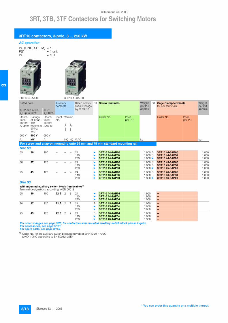
For screw and snap-on mounting onto 35 mm and 75 mm standard mounting railSize S3 65 30 100 -- -- -- 24 } 3RT10 44-1AB00 1.800 B 3RT10 44-3AB00 1.800
110 } 3RT10 44-1AF00 1.800 B 3RT10 44-3AF00 1.800230 } 3RT10 44-1AP00 1.800 } 3RT10 44-3AP00 1.800
80 37 120 -- -- -- 24 } 3RT10 45-1AB00 1.800 B 3RT10 45-3AB00 1.800110 } 3RT10 45-1AF00 1.800 B 3RT10 45-3AF00 1.800230 } 3RT10 45-1AP00 1.800 } 3RT10 45-3AP00 1.800
95 45 120 -- -- -- 24 } 3RT10 46-1AB00 1.800 B 3RT10 46-3AB00 1.800110 } 3RT10 46-1AF00 1.800 B 3RT10 46-3AF00 1.800230 } 3RT10 46-1AP00 1.800 } 3RT10 46-3AP00 1.800
Size S3 With mounted auxiliary switch block (removable)1)
Terminal designations according to EN 5001265 30 100 22 E 2 2 24 } 3RT10 44-1AB04 1.950 --
110 } 3RT10 44-1AF04 1.950 --230 } 3RT10 44-1AP04 1.950 --
80 37 120 22 E 2 2 24 B 3RT10 45-1AB04 1.950 --110 } 3RT10 45-1AF04 1.950 --230 } 3RT10 45-1AP04 1.950 --
95 45 120 22 E 2 2 24 B 3RT10 46-1AB04 1.950 --110 } 3RT10 46-1AF04 1.950 --230 } 3RT10 46-1AP04 1.950 --
For other voltages see page 3/25, for contactors with mounted auxiliary switch block please inquire.For accessories, see page 3/101.For spare parts, see page 3/115.
* You can order this quantity or a multiple thereof.
© Siemens AG 2008
3RT, 3TB, 3TF Contactors for Switching Motors
3RT10 contactors, 3-pole, 3 ... 250 kW
3/19Siemens LV 1 · 2008
3
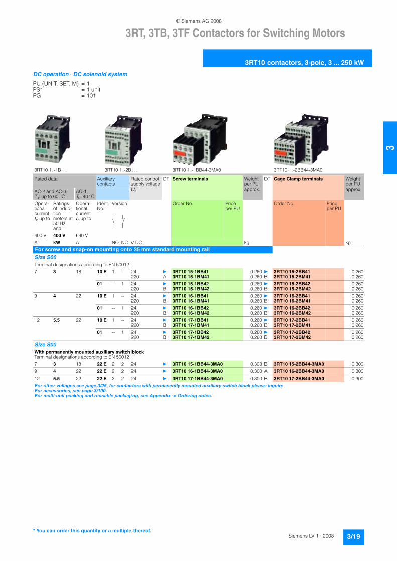
DC operation · DC solenoid system
PU (UNIT, SET, M) = 1PS* = 1 unitPG = 101
3RT10 1.-1B. . . 3RT10 1.-2B. . . 3RT10 1.-1BB44-3MA0 3RT10 1.-2BB44-3MA0
Rated data Auxiliary contacts
Rated control supply voltage Us
DT Screw terminals Weight per PU approx.
DT Cage Clamp terminals Weight per PU approx.AC-2 and AC-3,
Tu: up to 60 °CAC-1, Tu: 40 °C
Opera-tional current Ie up to
Ratings of induc-tion motors at 50 Hz and
Opera-tional current Ie up to
Ident. No.
Version Order No. Price per PU
Order No. Price per PU
400 V 400 V 690 VA kW A NO NC V DC kg kg
For screw and snap-on mounting onto 35 mm standard mounting railSize S00 Terminal designations according to EN 500127 3 18 10 E 1 -- 24 } 3RT10 15-1BB41 0.260 } 3RT10 15-2BB41 0.260
220 A 3RT10 15-1BM41 0.260 B 3RT10 15-2BM41 0.26001 -- 1 24 } 3RT10 15-1BB42 0.260 } 3RT10 15-2BB42 0.260
220 B 3RT10 15-1BM42 0.260 B 3RT10 15-2BM42 0.2609 4 22 10 E 1 -- 24 } 3RT10 16-1BB41 0.260 } 3RT10 16-2BB41 0.260
220 B 3RT10 16-1BM41 0.260 B 3RT10 16-2BM41 0.26001 -- 1 24 } 3RT10 16-1BB42 0.260 } 3RT10 16-2BB42 0.260
220 B 3RT10 16-1BM42 0.260 B 3RT10 16-2BM42 0.26012 5.5 22 10 E 1 -- 24 } 3RT10 17-1BB41 0.260 } 3RT10 17-2BB41 0.260
220 B 3RT10 17-1BM41 0.260 B 3RT10 17-2BM41 0.26001 -- 1 24 } 3RT10 17-1BB42 0.260 } 3RT10 17-2BB42 0.260
220 B 3RT10 17-1BM42 0.260 B 3RT10 17-2BM42 0.260
Size S00 With permanently mounted auxiliary switch blockTerminal designations according to EN 500127 3 18 22 E 2 2 24 } 3RT10 15-1BB44-3MA0 0.308 B 3RT10 15-2BB44-3MA0 0.3009 4 22 22 E 2 2 24 } 3RT10 16-1BB44-3MA0 0.300 A 3RT10 16-2BB44-3MA0 0.30012 5.5 22 22 E 2 2 24 } 3RT10 17-1BB44-3MA0 0.300 B 3RT10 17-2BB44-3MA0 0.300For other voltages see page 3/25, for contactors with permanently mounted auxiliary switch block please inquire.For accessories, see page 3/100.For multi-unit packing and reusable packaging, see Appendix -> Ordering notes.
* You can order this quantity or a multiple thereof.
© Siemens AG 2008

3RT, 3TB, 3TF Contactors for Switching Motors
3RT10 contactors, 3-pole, 3 ... 250 kW
3/20 Siemens LV 1 · 2008
3
DC operation · DC solenoid system
PU (UNIT, SET, M) = 1PS* = 1 unitPG = 101
1) Minimum conductor cross-section 10 mm².2) Order No. for the auxiliary switch block (removable): 3RH19 21-1HA22
(2NO + 2NC according to EN 50012; 22E).
3RT10 2.-1B.40 3RT10 2.-3B.40 3RT10 2.-3B.44 3RT10 2.-1BB44-3MA0
Rated data Auxiliary contacts
Rated control supply voltageUs
DT Screw terminals Weight per PU approx.
DT Cage Clamp terminals Weight per PU approx.
AC-2 and AC-3, Tu: up to 60 °C
AC-1, Tu: 40 °C
Opera-tional currentIe up to
Ratings of induc-tion motors at 50 Hz and
Opera-tional currentIe up to
Ident. No.
Version Order No. Price per PU
Order No. Price per PU
400 V 400 V 690 VA kW A NO NC V DC kg kg
For screw and snap-on mounting onto 35 mm standard mounting railsSize S0 9 4 401) -- -- -- 24 } 3RT10 23-1BB40 0.580 } 3RT10 23-3BB40 0.580
220 B 3RT10 23-1BM40 0.580 B 3RT10 23-3BM40 0.58012 5.5 401) -- -- -- 24 } 3RT10 24-1BB40 0.580 } 3RT10 24-3BB40 0.580
220 A 3RT10 24-1BM40 0.580 B 3RT10 24-3BM40 0.58017 7.5 401) -- -- -- 24 } 3RT10 25-1BB40 0.580 } 3RT10 25-3BB40 0.580
220 A 3RT10 25-1BM40 0.580 B 3RT10 25-3BM40 0.58025 11 401) -- -- -- 24 } 3RT10 26-1BB40 0.580 } 3RT10 26-3BB40 0.580
220 A 3RT10 26-1BM40 0.580 B 3RT10 26-3BM40 0.580
Size S0 With mounted auxiliary switch block (removable)2)
Terminal designations according to EN 500129 4 401) 22 E 2 2 24 } 3RT10 23-1BB44 0.650 --
220 B 3RT10 23-1BM44 0.650 --
12 5.5 401) 22 E 2 2 24 } 3RT10 24-1BB44 0.650 --220 B 3RT10 24-1BM44 0.650 --
17 7.5 401) 22 E 2 2 24 } 3RT10 25-1BB44 0.650 --220 B 3RT10 25-1BM44 0.650 --
25 11 401) 22 E 2 2 24 } 3RT10 26-1BB44 0.650 --220 B 3RT10 26-1BM44 0.650 --
Size S0 With permanently mounted auxiliary switch blockTerminal designations according to EN 5001212 5.5 401) 22 E 2 2 24 A 3RT10 24-1BB44-3MA0 0.650 --
17 7.5 401) 22 E 2 2 24 A 3RT10 25-1BB44-3MA0 0.650 --
25 11 401) 22 E 2 2 24 A 3RT10 26-1BB44-3MA0 0.650 --
For other voltages see page 3/25, for contactors with mounted auxiliary switch block please inquire.For accessories, see page 3/101.For multi-unit packing and reusable packaging, see Appendix -> Ordering notes.
* You can order this quantity or a multiple thereof.
© Siemens AG 2008

3RT, 3TB, 3TF Contactors for Switching Motors
3RT10 contactors, 3-pole, 3 ... 250 kW
3/21Siemens LV 1 · 2008
3
DC operation · DC solenoid system
PU (UNIT, SET, M) = 1PS* = 1 unitPG = 101
1) Order No. for the auxiliary switch block (removable): 3RH19 21-1HA22 (2NO + 2NC according to EN 50012; 22E).
3RT10 3.-1B.40 3RT10 4.-1B.40 3RT10 3.-3B.40 3RT10 4.-3B.40 3RT10 4.-1B.44
Rated data Auxiliary contacts
Rated control supply voltage Us
DT Screw terminals Weight per PU approx.
DT Cage Clamp terminals Weight per PU approx.
AC-2 and AC-3, Tu: up to 60 °C
AC-1, Tu: 40 °C
Opera-tional currentIe up to
Ratings of induc-tion motors at 50 Hz and
Opera-tional currentIe up to
Ident. No.
Version Order No. Price per PU
Order No. Price per PU
500 V 400 V 690 VA kW A NO NC V DC kg kg
For screw and snap-on mounting onto 35 mm standard mounting railSize S2 32 15 50 -- -- -- 24 } 3RT10 34-1BB40 1.450 } 3RT10 34-3BB40 1.450
220 A 3RT10 34-1BM40 1.450 B 3RT10 34-3BM40 1.45040 18.5 60 -- -- -- 24 } 3RT10 35-1BB40 1.450 } 3RT10 35-3BB40 1.450
220 B 3RT10 35-1BM40 1.450 B 3RT10 35-3BM40 1.45050 22 60 -- -- -- 24 } 3RT10 36-1BB40 1.450 } 3RT10 36-3BB40 1.450
220 B 3RT10 36-1BM40 1.450 A 3RT10 36-3BM40 1.450
Size S2 With mounted auxiliary switch block (removable)1)
Terminal designations according to EN 5001232 15 50 22 E 2 2 24 } 3RT10 34-1BB44 1.550 --
220 A 3RT10 34-1BM44 1.550 --
40 18.5 60 22 E 2 2 24 } 3RT10 35-1BB44 1.550 --220 B 3RT10 35-1BM44 1.550 --
50 22 60 22 E 2 2 24 } 3RT10 36-1BB44 1.550 --220 B 3RT10 36-1BM44 1.550 --
For screw and snap-on mounting onto 35 mm and 75 mm standard mounting railSize S3 65 30 100 -- -- -- 24 } 3RT10 44-1BB40 2.800 } 3RT10 44-3BB40 2.800
220 B 3RT10 44-1BM40 2.800 B 3RT10 44-3BM40 2.80080 37 120 -- -- -- 24 } 3RT10 45-1BB40 2.800 } 3RT10 45-3BB40 2.800
220 B 3RT10 45-1BM40 2.800 B 3RT10 45-3BM40 2.80095 45 120 -- -- -- 24 } 3RT10 46-1BB40 2.800 } 3RT10 46-3BB40 2.800
220 B 3RT10 46-1BM40 2.800 B 3RT10 46-3BM40 2.800
Size S3 With mounted auxiliary switch block (removable)1)
Terminal designations according to EN 5001265 30 100 22 E 2 2 24 } 3RT10 44-1BB44 2.900 --
220 B 3RT10 44-1BM44 2.900 --
80 37 120 22 E 2 2 24 } 3RT10 45-1BB44 2.900 --220 B 3RT10 45-1BM44 2.900 --
95 45 120 22 E 2 2 24 } 3RT10 46-1BB44 2.900 --220 B 3RT10 46-1BM44 2.900 --
For other voltages see page 3/25, for contactors with mounted auxiliary switch block please inquire.For accessories, see page 3/101. For spare parts, see page 3/115.For multi-unit packing and reusable packaging, see Appendix -> Ordering notes.
* You can order this quantity or a multiple thereof.
© Siemens AG 2008
3RT, 3TB, 3TF Contactors for Switching Motors
3RT10 contactors, 3-pole, 3 ... 250 kW
3/22 Siemens LV 1 · 2008
3
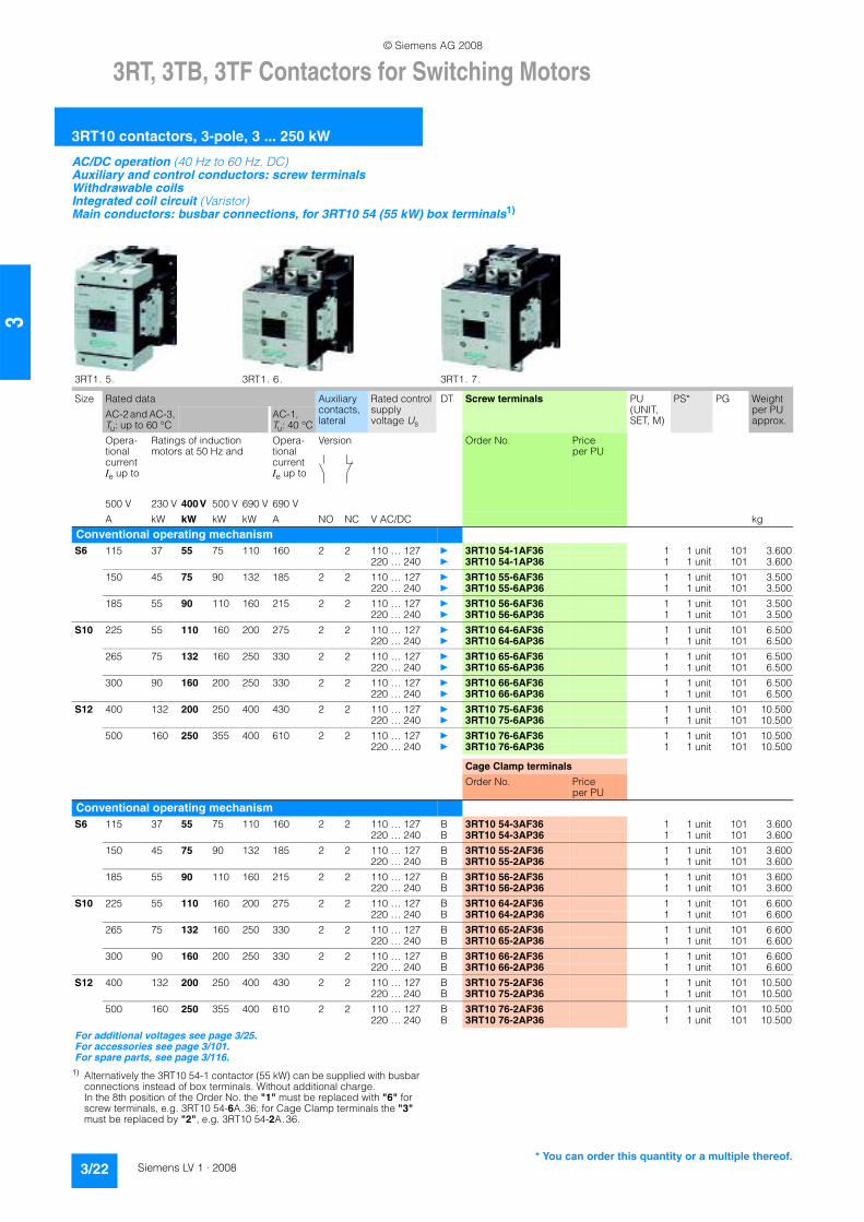
AC/DC operation (40 Hz to 60 Hz, DC)Auxiliary and control conductors: screw terminalsWithdrawable coils Integrated coil circuit (Varistor)Main conductors: busbar connections, for 3RT10 54 (55 kW) box terminals1)
1) Alternatively the 3RT10 54-1 contactor (55 kW) can be supplied with busbar connections instead of box terminals. Without additional charge. In the 8th position of the Order No. the "1" must be replaced with "6" for screw terminals, e.g. 3RT10 54-6A.36; for Cage Clamp terminals the "3"must be replaced by "2", e.g. 3RT10 54-2A.36.
3RT1. 5. 3RT1. 6. 3RT1. 7.
Size Rated data Auxiliary contacts, lateral
Rated control supply voltage Us
DT Screw terminals PU (UNIT, SET, M)
PS* PG Weight per PU approx.
AC-2 and AC-3, Tu: up to 60 °C
AC-1, Tu: 40 °C
Opera-tional currentIe up to
Ratings of induction motors at 50 Hz and
Opera-tional currentIe up to
Version Order No. Price per PU
500 V 230 V 400 V 500 V 690 V 690 VA kW kW kW kW A NO NC V AC/DC kg
Conventional operating mechanismS6 115 37 55 75 110 160 2 2 110 … 127 } 3RT10 54-1AF36 1 1 unit 101 3.600
220 … 240 } 3RT10 54-1AP36 1 1 unit 101 3.600150 45 75 90 132 185 2 2 110 … 127 } 3RT10 55-6AF36 1 1 unit 101 3.500
220 … 240 } 3RT10 55-6AP36 1 1 unit 101 3.500185 55 90 110 160 215 2 2 110 … 127 } 3RT10 56-6AF36 1 1 unit 101 3.500
220 … 240 } 3RT10 56-6AP36 1 1 unit 101 3.500S10 225 55 110 160 200 275 2 2 110 … 127 } 3RT10 64-6AF36 1 1 unit 101 6.500
220 … 240 } 3RT10 64-6AP36 1 1 unit 101 6.500265 75 132 160 250 330 2 2 110 … 127 } 3RT10 65-6AF36 1 1 unit 101 6.500
220 … 240 } 3RT10 65-6AP36 1 1 unit 101 6.500300 90 160 200 250 330 2 2 110 … 127 } 3RT10 66-6AF36 1 1 unit 101 6.500
220 … 240 } 3RT10 66-6AP36 1 1 unit 101 6.500S12 400 132 200 250 400 430 2 2 110 … 127 } 3RT10 75-6AF36 1 1 unit 101 10.500
220 … 240 } 3RT10 75-6AP36 1 1 unit 101 10.500500 160 250 355 400 610 2 2 110 … 127 } 3RT10 76-6AF36 1 1 unit 101 10.500
220 … 240 } 3RT10 76-6AP36 1 1 unit 101 10.500
Cage Clamp terminals
Order No. Price per PU
Conventional operating mechanismS6 115 37 55 75 110 160 2 2 110 … 127 B 3RT10 54-3AF36 1 1 unit 101 3.600
220 … 240 B 3RT10 54-3AP36 1 1 unit 101 3.600150 45 75 90 132 185 2 2 110 … 127 B 3RT10 55-2AF36 1 1 unit 101 3.600
220 … 240 B 3RT10 55-2AP36 1 1 unit 101 3.600185 55 90 110 160 215 2 2 110 … 127 B 3RT10 56-2AF36 1 1 unit 101 3.600
220 … 240 B 3RT10 56-2AP36 1 1 unit 101 3.600S10 225 55 110 160 200 275 2 2 110 … 127 B 3RT10 64-2AF36 1 1 unit 101 6.600
220 … 240 B 3RT10 64-2AP36 1 1 unit 101 6.600265 75 132 160 250 330 2 2 110 … 127 B 3RT10 65-2AF36 1 1 unit 101 6.600
220 … 240 B 3RT10 65-2AP36 1 1 unit 101 6.600300 90 160 200 250 330 2 2 110 … 127 B 3RT10 66-2AF36 1 1 unit 101 6.600
220 … 240 B 3RT10 66-2AP36 1 1 unit 101 6.600S12 400 132 200 250 400 430 2 2 110 … 127 B 3RT10 75-2AF36 1 1 unit 101 10.500
220 … 240 B 3RT10 75-2AP36 1 1 unit 101 10.500500 160 250 355 400 610 2 2 110 … 127 B 3RT10 76-2AF36 1 1 unit 101 10.500
220 … 240 B 3RT10 76-2AP36 1 1 unit 101 10.500For additional voltages see page 3/25. For accessories see page 3/101. For spare parts, see page 3/116.
* You can order this quantity or a multiple thereof.
© Siemens AG 2008

3RT, 3TB, 3TF Contactors for Switching Motors
3RT10 contactors, 3-pole, 3 ... 250 kW
3/23Siemens LV 1 · 2008
3
AC/DC operation (40 Hz to 60 Hz, DC)Auxiliary and control conductors: screw terminalsWithdrawable coils Integrated coil circuit (Varistor)Main conductors: busbar connections, for 3RT10 54 (55 kW) box terminals1)
1) Alternatively the 3RT10 54-1 contactor (55 kW) can be supplied with busbarconnections instead of box terminals. Without additional charge. In the 8th position of the Order No. the "1" must be replaced with "6" for screw terminals, e.g. 3RT10 54-6A.36; for Cage Clamp terminals the "3"must be replaced by "2", e.g. 3RT10 54-2A.36.
Size Rated data Auxiliary contacts, lateral
Rated control supply voltageUs
DT Screw terminals PU (UNIT, SET, M)
PS* PG Weight per PU approx.
AC-2 and AC-3, Tu: up to 60 °C
AC-1, Tu: 40 °C
Opera-tional currentIe up to
Ratings of induction motors at 50 Hz and
Opera-tional currentIe up to
Version Order No. Priceper PU
500 V 230 V 400 V 500 V 690 V 690 VA kW kW kW kW A NO NC V AC/DC kg
Solid-state operating mechanism · for 24 V DC PLC output S6 115 37 55 75 110 160 2 2 96 … 127 A 3RT10 54-1NF36 1 1 unit 101 3.500
200 … 277 } 3RT10 54-1NP36 1 1 unit 101 3.500150 45 75 90 132 185 2 2 96 … 127 A 3RT10 55-6NF36 1 1 unit 101 3.500
200 … 277 } 3RT10 55-6NP36 1 1 unit 101 3.500185 55 90 110 160 215 2 2 96 … 127 A 3RT10 56-6NF36 1 1 unit 101 3.500
200 … 277 } 3RT10 56-6NP36 1 1 unit 101 3.500S10 225 55 110 160 200 275 2 2 96 … 127 A 3RT10 64-6NF36 1 1 unit 101 6.700
200 … 277 A 3RT10 64-6NP36 1 1 unit 101 6.700265 75 132 160 250 330 2 2 96 … 127 A 3RT10 65-6NF36 1 1 unit 101 6.700
200 … 277 A 3RT10 65-6NP36 1 1 unit 101 6.700300 90 160 200 250 330 2 2 96 … 127 B 3RT10 66-6NF36 1 1 unit 101 6.700
200 … 277 A 3RT10 66-6NP36 1 1 unit 101 6.700S12 400 132 200 250 400 430 2 2 96 … 127 A 3RT10 75-6NF36 1 1 unit 101 10.500
200 … 277 A 3RT10 75-6NP36 1 1 unit 101 10.500500 160 250 355 400 610 2 2 96 … 127 A 3RT10 76-6NF36 1 1 unit 101 10.500
200 … 277 A 3RT10 76-6NP36 1 1 unit 101 10.500
Cage Clamp terminals
Order No. Price per PU
Solid-state operating mechanism · for 24 V DC PLC output S6 115 37 55 75 110 160 2 2 96 … 127 B 3RT10 54-3NF36 1 1 unit 101 3.500
200 … 277 B 3RT10 54-3NP36 1 1 unit 101 3.500150 45 75 90 132 185 2 2 96 … 127 B 3RT10 55-2NF36 1 1 unit 101 3.500
200 … 277 B 3RT10 55-2NP36 1 1 unit 101 3.500185 55 90 110 160 215 2 2 96 … 127 B 3RT10 56-2NF36 1 1 unit 101 3.500
200 … 277 B 3RT10 56-2NP36 1 1 unit 101 3.500S10 225 55 110 160 200 275 2 2 96 … 127 B 3RT10 64-2NF36 1 1 unit 101 6.700
200 … 277 B 3RT10 64-2NP36 1 1 unit 101 6.700265 75 132 160 250 330 2 2 96 … 127 B 3RT10 65-2NF36 1 1 unit 101 6.700
200 … 277 B 3RT10 65-2NP36 1 1 unit 101 6.700300 90 160 200 250 330 2 2 96 … 127 B 3RT10 66-2NF36 1 1 unit 101 6.700
200 … 277 B 3RT10 66-2NP36 1 1 unit 101 6.700S12 400 132 200 250 400 430 2 2 96 … 127 B 3RT10 75-2NF36 1 1 unit 101 10.500
200 … 277 B 3RT10 75-2NP36 1 1 unit 101 10.500500 160 250 355 400 610 2 2 96 … 127 B 3RT10 76-2NF36 1 1 unit 101 10.500
200 … 277 B 3RT10 76-2NP36 1 1 unit 101 10.500
For additional voltages see page 3/25. For accessories see page 3/101. For spare parts, see page 3/114.
* You can order this quantity or a multiple thereof.
© Siemens AG 2008

3RT, 3TB, 3TF Contactors for Switching Motors
3RT10 contactors, 3-pole, 3 ... 250 kW
3/24 Siemens LV 1 · 2008
3
1) Alternatively the 3RT10 54-1 contactor (55 kW) can be supplied with busbarconnections instead of box terminals. Without additional charge. In the 8th position of the Order No. the "1" must be replaced with "6", e.g. 3RT10 54-6. .35.
AC/DC operation (40 Hz to 60 Hz, DC)Auxiliary and control conductors: screw terminalsWithdrawable coils Integrated coil circuit (Varistor)Main conductors: busbar connections, for 3RT10 54 (55 kW) box terminals1)
Remaining lifetime indicator (RLT)
3RT10 56-6P. . 3RT10 56-6Q. .
Size Rated data Auxiliary contacts, lateral
Rated control supply voltageUs
DT Screw terminals PU (UNIT, SET, M)
PS* PG Weight per PU approx.
AC-2 and AC-3, Tu: up to 60 °C
AC-1, Tu: 40 °C
Opera-tional current Ie up to
Ratings of induction motors at 50 Hz and
Opera-tional current Ie up to
Order No. Price per PU
500 V 230 V 400 V 500 V 690 V 690 VA kW kW kW kW A NO NC V AC/DC kg
Solid-state operating mechanism for 24 V DC PLC output/PLC relay output, with remaining lifetime indicator (RLT)S6 115 37 55 75 110 160 1 1 96 … 127 B 3RT10 54-1PF35 1 1 unit 101 4.000
200 … 277 B 3RT10 54-1PP35 1 1 unit 101 4.000150 45 75 90 132 185 1 1 96 … 127 B 3RT10 55-6PF35 1 1 unit 101 4.000
200 … 277 B 3RT10 55-6PP35 1 1 unit 101 4.000185 55 90 110 160 215 1 1 96 … 127 B 3RT10 56-6PF35 1 1 unit 101 4.000
200 … 277 B 3RT10 56-6PP35 1 1 unit 101 4.000S10 225 55 110 160 200 275 1 1 96 … 127 B 3RT10 64-6PF35 1 1 unit 101 7.000
200 … 277 B 3RT10 64-6PP35 1 1 unit 101 7.000265 75 132 160 250 330 1 1 96 … 127 B 3RT10 65-6PF35 1 1 unit 101 7.000
200 … 277 B 3RT10 65-6PP35 1 1 unit 101 7.000300 90 160 200 250 330 1 1 96 … 127 B 3RT10 66-6PF35 1 1 unit 101 7.000
200 … 277 B 3RT10 66-6PP35 1 1 unit 101 7.000S12 400 132 200 250 400 430 1 1 96 … 127 B 3RT10 75-6PF35 1 1 unit 101 10.500
200 … 277 B 3RT10 75-6PP35 1 1 unit 101 10.500500 160 250 355 400 610 1 1 96 … 127 B 3RT10 76-6PF35 1 1 unit 101 10.500
200 … 277 B 3RT10 76-6PP35 1 1 unit 101 10.500
Solid-state operating mechanism · with AS-Interface and remaining lifetime indicator (RLT)S6 115 37 55 75 110 160 1 1 96 … 127 B 3RT10 54-1QF35 1 1 unit 101 4.000
200 … 277 B 3RT10 54-1QP35 1 1 unit 101 4.000150 45 75 90 132 185 1 1 96 … 127 B 3RT10 55-6QF35 1 1 unit 101 4.000
200 … 277 B 3RT10 55-6QP35 1 1 unit 101 4.000185 55 90 110 160 215 1 1 96 … 127 B 3RT10 56-6QF35 1 1 unit 101 4.000
200 … 277 B 3RT10 56-6QP35 1 1 unit 101 4.000S10 225 55 110 160 200 275 1 1 96 … 127 B 3RT10 64-6QF35 1 1 unit 101 7.000
200 … 277 B 3RT10 64-6QP35 1 1 unit 101 7.000265 75 132 160 250 330 1 1 96 … 127 B 3RT10 65-6QF35 1 1 unit 101 7.000
00 … 277 B 3RT10 65-6QP35 1 1 unit 101 7.000300 90 160 200 250 330 1 1 96 … 127 B 3RT10 66-6QF35 1 1 unit 101 7.000
200 … 277 B 3RT10 66-6QP35 1 1 unit 101 7.000S12 400 132 200 250 400 430 1 1 96 … 127 B 3RT10 75-6QF35 1 1 unit 101 10.500
200 … 277 B 3RT10 75-6QP35 1 1 unit 101 10.500500 160 250 355 400 610 1 1 96 … 127 B 3RT10 76-6QF35 1 1 unit 101 10.500
200 … 277 B 3RT10 76-6QP35 1 1 unit 101 10.500
For additional voltages see page 3/25. For accessories see page 3/101.For spare parts, see page 3/116.
* You can order this quantity or a multiple thereof.
© Siemens AG 2008

3RT, 3TB, 3TF Contactors for Switching Motors
3RT10 contactors, 3-pole, 3 ... 250 kW
3/25Siemens LV 1 · 2008
3
Rated control supply voltages (the 10th and 11th position of the order number must be changed)
1) For deviating coil voltages and coil operating ranges of sizes S00 and S0, the 24 V DC SITOP Power power supply with wide range input (93 to 264 V AC;30 to 264 V DC) can be used for coil excitation (see "Power Supplies" --> "SITOP Power Power Supplies").
2) Coil operating range at 50 Hz: 0.8 to 1.1 x Usat 60 Hz: 0.85 to 1.1 x Us.
3) Coil operating rangeSize S00: at 50 Hz: 0.85 to 1.1 x Us
at 60 Hz: 0.8 to 1.1 x UsSizes S0 to S3: at 50 Hz and 60 Hz: 0.8 to 1.1 x Us.
4) Coil operating rangeSize S00: at 50/60 Hz: 0.85 to 1.1 x UsSizes S0 to S3: at 50 Hz: 0.8 to 1.1 x Us
at 60 Hz: 0.85 to 1.1 x Us.5) Coil operating range at 60 Hz: 0.8 to 1.1 x Us.6) Operating range: 0.8 x Us min to 1.1 x Us max.
Contactor type 3RT10 1 3RT10 2, 3RT10 3, 3RT10 4
3RT14 4 3RT13 1, 3RT15 1
3RT13 2 ... 3RT13 4, 3RT15 2 and 3RT15 3
3RT16
Rated control supply voltage Us
Sizes S00 ... S3AC operation1)
Magnetic coils for 50 Hz (exception: size S00: 50 and 60 Hz2))
24 V AC B0 B0 B0 B0 B0 B042 V AC D0 D0 D0 D0 -- --48 V AC H0 H0 H0 H0 -- --
110 V AC F0 F0 F0 F0 F0 F0230 V AC P0 P0 P0 P0 P0 P0400 V AC V0 V0 V0 V0 V0 V0Magnetic coils for 50 and 60 Hz2)24 V AC B0 C2 C2 B0 C2 C242 V AC D0 D2 D2 D0 D2 --48 V AC H0 H2 H2 H0 H2 --
110 V AC F0 G2 G2 F0 G2 G2220 V AC N2 N2 N2 N2 N2 N2230 V AC P0 L2 L2 P0 L2 L2Magnetic coils (for USA and Canada3))
50 Hz 60 Hz
110 V AC 120 V AC K6 K6 K6 K6 K6 K6220 V AC 240 V AC P6 P6 P6 P6 P6 P6Magnetic coils (for Japan)
50/60 Hz4) 60 Hz5)
100 V AC 110 V AC G6 G6 G6 G6 G6 G6200 V AC 220 V AC N6 N6 N6 N6 N6 N6400 V AC 440 V AC R6 R6 R6 R6 R6 R6
DC operation1)
12 V DC A4 -- -- A4 -- --24 V DC B4 B4 B4 B4 B4 --42 V DC D4 D4 D4 D4 D4 --48 V DC W4 W4 W4 W4 -- --60 V DC E4 E4 E4 -- -- --
110 V DC F4 F4 F4 F4 F4 --125 V DC G4 G4 G4 G4 G4 --220 V DC M4 M4 M4 M4 M4 --230 V DC P4 P4 P4 P4 -- --
Sizes S6 ... S12AC/DC operation (AC 40 ... 60 Hz, DC)Conventional operating mechanism
Us min ... Us max6)
Contactor type 3RT1. 5.-.A3RT1. 6.-.A3RT1. 7.-.A
Us min ... Us max6)
Contactor type 3RT1. 5.-.A3RT1. 6.-.A3RT1. 7.-.A
23 ... 26 V AC/DC B3 240 ... 277 V AC/DC U342 ... 48 V AC/DC D3 380 ... 420 V AC/DC V3
110 ... 127 V AC/DC F3 440 ... 480 V AC/DC R3200 ... 220 V AC/DC M3 500 ... 550 V AC/DC S3220 ... 240 V AC/DC P3 575 ... 600 V AC/DC T3Solid-state operating mechanism
Us min ... Us max6)
Contactor type 3RT1. 5.-.N3RT1. 6.-.N3RT1. 7.-.N
3RT1. 5.-.P/Q3RT1. 6.-.P/Q3RT1. 7.-.P/Q
21 ... 27.3 V AC/DC B3 --96 ... 127 V AC/DC F3 F3
200 ... 277 V AC/DC P3 P3
ExamplesAC operating mechanism
3RT10 23-1AP00 Contactor with screw terminals; with magnetic coil for 50 Hz for rated control supply voltage 230 V AC.3RT10 23-1AG20 Contactor with screw terminals; with magnetic coil for 50/60 Hz for rated control supply voltage 110 V AC.
DC operating mechanism
3RT10 34-3BB40 Contactor with Cage Clamp terminals; for rated control supply voltage 24 V DC.3RT10 34-3BG40 Contactor with Cage Clamp terminals; for rated control supply voltage 125 V DC.
© Siemens AG 2008