Controlling the Morphology of Polyurea Microcapsules Using...
6
Controlling the Morphology of Polyurea Microcapsules Using Microfluidics Ingmar Polenz, †,‡ Sujit S. Datta, †,§ and David A. Weitz* ,† † School of Engineering and Applied Sciences, Harvard University, 29 Oxford Street, Cambridge, Massachusetts 02138, United States ‡ Max-Planck Institute for Dynamics and Self-organization, Am Fassberg 17, 37077 Gö ttingen, Germany § California Institute of Technology, 1200 East California Boulevard, Pasadena, California 91125, United States * S Supporting Information ABSTRACT: We use microfluidics to continuously produce monodisperse polyurea microcapsules (PUMCs) having either aqueous or nonaqueous cores. The microcapsule shells are formed by the reaction between an isocyanate, dissolved in oil, and an amine, dissolved in water, at the surface of oil-in-water or water-in-oil drops immediately as they are formed. Different microcapsule morpholo- gies can be generated using our approach. The thickness of the microcapsule shell increases with an increase in the amine solubility in the oil; this finding provides a simple mechanism by which the PUMC shell thickness can be controlled. ■ INTRODUCTION Microcapsules are promising candidates for important applications requiring the encapsulation, delivery, and release of active materials, such as self-healing materials, catalysts, agricultural chemicals, textile chemicals, and chemicals used in paper manufacturing. 1−17 Polyurea microcapsules (PUMCs) are particularly attractive for their chemical and mechanical stability. 18−27 They are fabricated by forming drops of oil containing an isocyanate in an aqueous phase containing an amine: as they come into contact at the oil−water interfaces, the isocyanate and the amine quickly react, forming solid polyurea shells around the oil drops. Such droplet templates are typically fabricated using a variety of approaches, such as spray drying, coextrusion, and phase separation; however, because of the highly variable shear used, the sizes and morphologies of the resultant microcapsules can vary enormously. 24−27 More- over, these fabrication approaches are typically limited to producing oil-in-water (O/W) emulsion templates and, thus, PUMCs with nonaqueous cores; this precludes the use of PUMCs to encapsulate hydrophilic actives, such as agricultural chemicals, hydrophilic drugs, or cells. The precise flow control afforded by microfluidic technol- ogies provides a potential means of overcoming these limitations. For example, a glass capillary microfluidic device can be used to produce highly monodisperse O/W or water-in- oil (W/O) emulsion drops. 28−32 In this approach, the PUMC shell forms by the reaction between an amine and an isocyanate at the surface of each drop immediately as it is produced. However, because of the rapidity of the shell generation, solid polyurea can form at the oil−water interface even before the emulsion drop is fully formed, ultimately clogging the microfluidic device. This prevents the unimpeded fabrication of large quantities of PUMCs. A microfluidic approach to continuously fabricating monodisperse PUMCs is thus highly desirable. Here, we report a straightforward microfluidic approach to continuously fabricate monodisperse PUMCs, without clogging of the device, using single emulsion drops as templates. This approach is versatile, allowing us to produce PUMCs having either nonaqueous or aqueous cores. We systematically study how different PUMC morphologies can be generated using our approach. Interestingly, the PUMC shell thickness is strongly dependent on the solubility of the amine in the oil phase used; this finding provides a simple mechanism by which the PUMC shell thickness can be tuned over a broad range, spanning tens of nanometers to several micrometers. ■ MATERIALS AND METHODS Materials. The isocyanates 1,6-hexamethylene diisocyanate (HDI) and 2,4-toluene diisocyanate (TDI), the amines 1,6-hexamethylenedi- amine (HMDA), polyethylenimine (PEI, branched; M n = 800 g/mol), ethylenediamine (En), and tetraethylenepentamine (TEPA), the surfactant sodium dodecyl sulfate (SDS), a sodium silicate solution (water glass, ∼10.6% Na 2 O, 26.5% SiO 2 ), and trimethoxy(octyl)silane were purchased in the highest available purity grade from Sigma- Aldrich and used without former purification. The multifunctional HDI trimer Basonat H100 was purchased from BASF SE, the Received: August 19, 2014 Revised: October 15, 2014 Article pubs.acs.org/Langmuir © XXXX American Chemical Society A dx.doi.org/10.1021/la503234z | Langmuir XXXX, XXX, XXX−XXX
Transcript of Controlling the Morphology of Polyurea Microcapsules Using...
Controlling the Morphology of Polyurea Microcapsules UsingMicrofluidicsIngmar Polenz,†,‡ Sujit S. Datta,†,§ and David A. Weitz*,†
†School of Engineering and Applied Sciences, Harvard University, 29 Oxford Street, Cambridge, Massachusetts 02138, United States‡Max-Planck Institute for Dynamics and Self-organization, Am Fassberg 17, 37077 Gottingen, Germany§California Institute of Technology, 1200 East California Boulevard, Pasadena, California 91125, United States
*S Supporting Information
ABSTRACT: We use microfluidics to continuously producemonodisperse polyurea microcapsules (PUMCs) having eitheraqueous or nonaqueous cores. The microcapsule shells are formedby the reaction between an isocyanate, dissolved in oil, and an amine,dissolved in water, at the surface of oil-in-water or water-in-oil dropsimmediately as they are formed. Different microcapsule morpholo-gies can be generated using our approach. The thickness of themicrocapsule shell increases with an increase in the amine solubilityin the oil; this finding provides a simple mechanism by which thePUMC shell thickness can be controlled.
■ INTRODUCTION
Microcapsules are promising candidates for importantapplications requiring the encapsulation, delivery, and releaseof active materials, such as self-healing materials, catalysts,agricultural chemicals, textile chemicals, and chemicals used inpaper manufacturing.1−17 Polyurea microcapsules (PUMCs)are particularly attractive for their chemical and mechanicalstability.18−27 They are fabricated by forming drops of oilcontaining an isocyanate in an aqueous phase containing anamine: as they come into contact at the oil−water interfaces,the isocyanate and the amine quickly react, forming solidpolyurea shells around the oil drops. Such droplet templates aretypically fabricated using a variety of approaches, such as spraydrying, coextrusion, and phase separation; however, because ofthe highly variable shear used, the sizes and morphologies ofthe resultant microcapsules can vary enormously.24−27 More-over, these fabrication approaches are typically limited toproducing oil-in-water (O/W) emulsion templates and, thus,PUMCs with nonaqueous cores; this precludes the use ofPUMCs to encapsulate hydrophilic actives, such as agriculturalchemicals, hydrophilic drugs, or cells.The precise flow control afforded by microfluidic technol-
ogies provides a potential means of overcoming theselimitations. For example, a glass capillary microfluidic devicecan be used to produce highly monodisperse O/W or water-in-oil (W/O) emulsion drops.28−32 In this approach, the PUMCshell forms by the reaction between an amine and an isocyanateat the surface of each drop immediately as it is produced.However, because of the rapidity of the shell generation, solidpolyurea can form at the oil−water interface even before the
emulsion drop is fully formed, ultimately clogging themicrofluidic device. This prevents the unimpeded fabricationof large quantities of PUMCs. A microfluidic approach tocontinuously fabricating monodisperse PUMCs is thus highlydesirable.Here, we report a straightforward microfluidic approach to
continuously fabricate monodisperse PUMCs, without cloggingof the device, using single emulsion drops as templates. Thisapproach is versatile, allowing us to produce PUMCs havingeither nonaqueous or aqueous cores. We systematically studyhow different PUMC morphologies can be generated using ourapproach. Interestingly, the PUMC shell thickness is stronglydependent on the solubility of the amine in the oil phase used;this finding provides a simple mechanism by which the PUMCshell thickness can be tuned over a broad range, spanning tensof nanometers to several micrometers.
■ MATERIALS AND METHODSMaterials. The isocyanates 1,6-hexamethylene diisocyanate (HDI)
and 2,4-toluene diisocyanate (TDI), the amines 1,6-hexamethylenedi-amine (HMDA), polyethylenimine (PEI, branched; Mn = 800 g/mol),ethylenediamine (En), and tetraethylenepentamine (TEPA), thesurfactant sodium dodecyl sulfate (SDS), a sodium silicate solution(water glass, ∼10.6% Na2O, 26.5% SiO2), and trimethoxy(octyl)silanewere purchased in the highest available purity grade from Sigma-Aldrich and used without former purification. The multifunctionalHDI trimer Basonat H100 was purchased from BASF SE, the
Received: August 19, 2014Revised: October 15, 2014
Article
pubs.acs.org/Langmuir
© XXXX American Chemical Society A dx.doi.org/10.1021/la503234z | Langmuir XXXX, XXX, XXX−XXX
surfactant Abil EM 90 from Evonik Industries, and 2-[methoxy-(polyethylenoxypropyl)]9−12trimethoxysilane from Gelest, Inc.Microfluidics and PUMC Preparation. The polyurea micro-
capsules (PUMCs) are prepared using glass-capillary-based micro-fluidic devices. Round capillaries (World Precision Instruments, Inc.,Sarasota, FL) with an inner diameter of 0.64 mm and an outerdiameter of 1.00 mm are tapered to desired diameters by applying amicropipette puller (P-97, Sutter Instrument, Inc.). The inner capillarytip diameter is 20 μm and that of the outlet 200 μm. The roundcapillary is inserted inside a square glass capillary (AtlanticInternational Technology, Inc., Rockaway, NJ; dinner = 1.05 mm),whereas the inner fluid capillary tip is aligned centrosymmetrically withthe outlet with a distance of 40 μm before it. The capillaries are sealedusing a transparent epoxy resin (5 min Epoxy, Devcon, Danvers, MA).Glass capillary devices prepared after this method tend to clog at theinner fluid capillary tip region after approximately 1.5 h. To overcomethis problem, an additional solvent/surfactant stream between themiddle and outer fluid is integrated. By means of this technique,PUMC generation can be performed for several hours, easily. WhenO/W PUMCs are prepared, the round capillaries are treated with 2-[methoxy(polyethylenoxypropyl)]9−12trimethoxysilane for 15 min; forthe W/O capsule preparation, trimethoxy(octadecyl)silane is used. Aphotograph of the microcapillary glass device and the schematic of thework flows are shown in Figure S1 of the Supporting Information.The inner fluid containing either the amine or the isocyanate, the
middle fluid containing the continuous fluid and surfactant, and theouter fluid flow containing either the isocyanate or the amine areinjected into the device at desired flow rates using syringe pumps (NE-501, New Era Pump Systems, Inc., Farmingdale, NY). The amine isalways dissolved in deionized water and the isocyanate in the oil. Thetypical flow rates for the inner, middle, and outer fluid phases are 500,6000, and 7000 μL h−1, respectively. The contact of the outer andinner fluid material at the oil−water interface occurs by diffusivemixing. The outlet tubing leads into a container, within which thecapsules are gently collected. After 18 h at room temperature, thesupernatant fluid of the PUMC suspension is decanted several timesand replaced with pure continuous fluid. In the case of the W/OPUMCs except from the experiments with PEI, a turbid continuousfluid was observed as a result of the bulk polyurea formation caused bythe migration of the amine into the continuous media.The liquid−liquid interfacial tension for cyclohexene and SDS
(aqueous) in O/W mode is 2.78 ± 0.16 mN m−1 and at thecyclohexene with Abil EM 90 anc deionized water in W/O mode is12.06 ± 0.31 mN m−1, which is measured by means of the pendentdrop method, using custom image processing in MATLAB.
■ RESULTS AND DISCUSSION
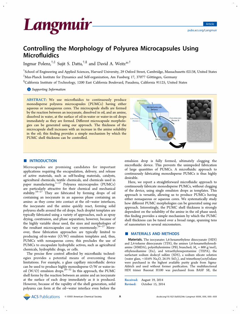
Preparation of Monodisperse PUMCs. We use a glasscapillary microfluidic device to prepare monodisperse O/Wemulsion drops as templates to form PUMCs; a schematic isshown in Figure 1a, and a photograph is shown in Figure S1 ofthe Supporting Information.28−32 The device consists of twotapered cylindrical capillaries inserted into the opposite ends ofa square capillary, whose inner dimension is slightly larger thanthe outer dimension of the cylindrical capillaries. Thisconfiguration allows us to accurately align both cylindricalcapillaries. The dispersed oil phase is a 3 wt % solution of 2,4-toluene diisocyanate (TDI) in cyclohexane and is injected usingthe cylindrical capillary shown on the left in the figure. We treatthis capillary with 2-[methoxy(polyethylenoxypropyl)]-trimethoxysilane; this renders its surface hydrophilic, prevent-ing wetting of the oil on the capillary wall. The continuousphase is a 3 wt % aqueous solution of tetraethylenepentamine(TEPA) and is injected from the right; this forces it to flow inthe direction that is the opposite of that of the dispersed phase,through the interstitial space between the right cylindricalcapillary and the square capillary. The isocyanate reacts,
forming solid polyurea, when it contacts the amine-containingaqueous phase; if this occurs too close to the tip of the leftcylindrical capillary, the device clogs, preventing its furtheroperation. We overcome this problem by injecting an additionalcontinuous phase, a 3 wt % aqueous solution of sodium dodecylsulfate (SDS), from the left, forcing it to flow in the samedirection as the dispersed oil phase, through the interstitialspace between the left cylindrical capillary and the squarecapillary. We operate this hydrodynamic focusing geometry inthe dripping regime, causing the oil to break up at the entranceto the right cylindrical capillary. This protocol formsmonodisperse O/W emulsion drops robustly for more thanseveral hours; a representative optical micrograph is shown inFigure 1b.We use the right cylindrical capillary to collect these
emulsion drops; the capillary is treated with 2-[methoxy-(polyethyleneoxy)propyl]trimethoxysilane, rendering its surfacehydrophilic and preventing wetting of the oil on the capillarywall. The isocyanate within the drops and the amine in thecontinuous phase react at the drop surfaces, quickly formingmicrocapsules, with uniform polyurea shells surrounding the oilcores, over a time scale of approximately 0.1−1 s. The PUMCsthus formed are collected, and the supernatant is removed andreplaced with water several times to remove any surfactant fromthe continuous phase. This approach generates solid micro-capsules (Supporting Information); an optical micrograph isshown in Figure 2a. Because of the monodisperse nature of thedrop templates used to form them, the PUMCs thus producedare highly monodisperse; the polydispersity in their sizes is∼4−6%, as shown by the data in Figure 2b. The PUMCs areslightly wrinkled; this may result from slight evaporation of thefluid from the core or could be due to the reduction of the corevolume due to the amine being used to form the shell.The precise flow control afforded by microfluidics allows us
to prepare microcapsules of varying sizes. We do this by varyingthe ratio between the flow rate of the dispersed oil phase, QD,and the sum of the flow rates of the dispersed, amine-containing continuous, and surfactant-containing continuousphases (QD, QC1, and QC2, respectively). The size of theemulsion drops produced and, hence, the resultant PUMCsincreases with increasing xD = QD/(QD + QC1 + QC2), asexemplified by the green squares in Figure 2c. This provides astraightforward means of tuning the PUMC size.Our experimental approach can be used to fabricate PUMCs
of different compositions. To illustrate its versatility, we use the
Figure 1. (a) Schematic illustration of the glass capillary microfluidicdevice used for polyurea microcapsule generation from emulsion droptemplates. (b) Optical micrograph of the region in panel a, showingthe generation of monodisperse emulsion drop templates.
Langmuir Article
dx.doi.org/10.1021/la503234z | Langmuir XXXX, XXX, XXX−XXXB

same microfluidic device, but different dispersed andcontinuous phases. In particular, we use this approach toprepare PUMCs with aqueous cores. To achieve this, we use a3 wt % aqueous solution of TEPA as the inner phase and 3 wt% solutions of Abil EM 90 and TDI in cyclohexane as thesurfactant- and isocyanate-containing continuous phases,respectively. The left and right cylindrical capillaries are treatedwith trimethoxy(octadecyl)silane; this renders their surfaceshydrophobic, preventing wetting of the water on the capillary
wall. We again operate the microfluidic device in the drippingmode, thereby generating monodisperse W/O emulsion drops.The reaction between the TEPA and TDI again leads to theformation of a uniform polyurea shell; however, in this case, themicrocapsule core is aqueous. As with the previous case, we usethe flow control allowed by microfluidics to tune the sizes ofthe resultant PUMCs: by changing xD, we can tune the PUMCdiameter over the range of 50−100 μm, as shown by the bluetriangles in Figure 2c.
Figure 2. (a) Optical micrograph showing PUMCs with aqueous cores after collection. (b) Distribution of diameters of the PUMCs shown in panela, with a Gaussian fit. (c) PUMC diameters increase with an increase in xD, the fractional flow rate of the dispersed phase, for PUMCs formed fromW/O or O/W emulsion drop templates. The PUMCs in all three panels are formed using cyclohexane as the oil, TDI as the isocyanate, and TEPA asthe amine; we use Abil EM 90 (2.5 wt %) or SDS (5 wt %) as the surfactant for PUMCs formed from W/O or O/W templates, respectively. Errorbars show one standard deviation of the microcapsule size distribution.
Figure 3. (a) PUMC shell thickness increases with increasing amine solubility in the oil phase, KOW. We use four different amines and show theirchemical structures. Toluene is the oil phase. (a and b) Scanning electron micrographs of PUMC shells formed from (a) O/W and (b) W/Oemulsion templates. (c) Average microcapsule shell thicknesses for varying amines, characterized by different KOW values. Error bars show onestandard deviation of the microcapsule size distribution; bars for small values of KOW are smaller than the symbols.
Langmuir Article
dx.doi.org/10.1021/la503234z | Langmuir XXXX, XXX, XXX−XXXC
Amine Solubility Determines PUMC Shell Thickness.To elucidate how the shell thickness of the microcapsulesdepends on the chemical components used, we fabricatePUMCs using four different amines: TEPA, polyethylenimine(PEI), ethylenediamine (En), and 1,6-hexamethylenediamine(HMDA). We use TDI as the isocyanate and toluene as the oilphase. The amines are slightly soluble in the toluene, to varyingextents. This variation can be quantified using the aminepartitioning coefficient:33 KOW = [amine]O/[amine]W, where[amine]O and [amine]W are the equilibrium concentrations ofthe amine in the oil and water phases, respectively. Wedetermine these concentrations using bulk experiments (detailsin the Supporting Information). Interestingly, the shellthickness increases with an increase in KOW, as exemplified bythe scanning electron micrographs shown in panels a and b ofFigure 3, and summarized by the data in Figure 3c. Forexample, the PUMCs formed from PEI, which is insoluble intoluene and thus has a KOW of ≈0, are only 90−110 nm thick;by contrast, the PUMCs formed from HMDA, which has a KOWof ≈0.05, have shells an order of magnitude thicker (1.5−2.5μm). This behavior appears to be independent of the nature ofthe emulsion template: we use our microfluidic approach toprepare both O/W and W/O templates, which ultimately formPUMCs having nonaqueous and aqueous cores, respectively. Inboth cases, the PUMC shell thickness increases with an increasein amine solubility in the oil, as shown by the squares andtriangles in Figure 3c. Elucidating the exact mechanism limiting
shell growth, for a given amine solubility, will be an importantand interesting route for future work.To further test the influence of amine solubility on PUMC
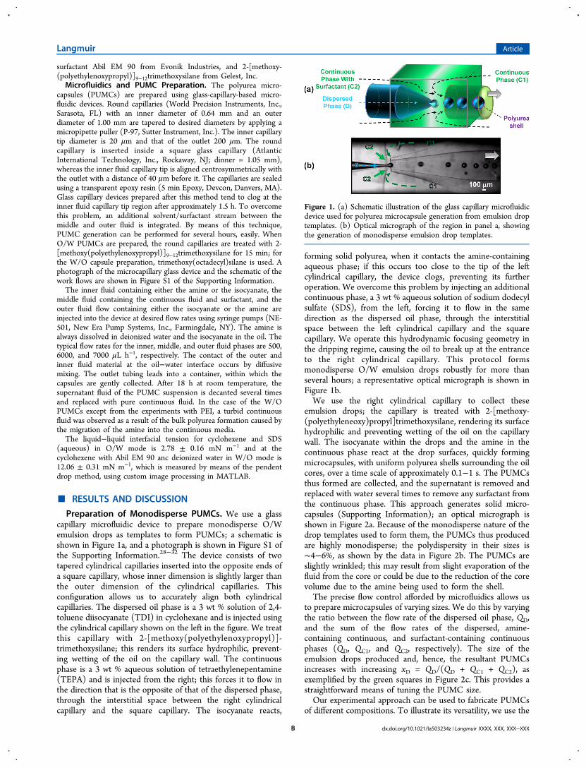
shell geometry, we fabricate PUMCs from O/W emulsiontemplates, with 1,6-hexamethylene diisocyanate (HDI) as theisocyanate and HMDA as the amine, using three different oils:n-hexane, KMC 113 oil, and dichloromethane (DCM). The oilsare characterized by KOW values that vary over an order ofmagnitude, from 0.025 to 0.239. Consistent with our previousresults, we find that the PUMC shell thickness increases withincreasing KOW, as shown by the scanning electron microscopy(SEM) micrographs in panels a and b of Figure 4. Intriguingly,for the case of DCM, which has the highest value of KOW, wedo not even observe the formation of a well-defined PUMCshell; instead, the microcapsules have a spongelike appearance,as shown by the micrographs in Figure 4c and Figure S4 of theSupporting Information. This may, for example, reflectinteractions with the surfactant at the surface of the PUMCdroplet template.Our data indicate that the structure of the microcapsule shell
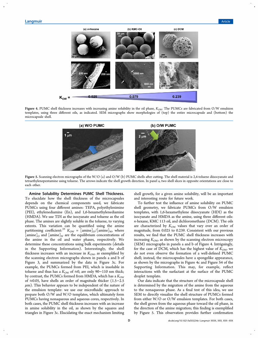
is determined by the migration of the amine from the aqueousto the nonaqueous phase. As a final test of this idea, we useSEM to directly visualize the shell structure of PUMCs formedfrom either W/O or O/W emulsion templates. For both cases,the shell grows from the aqueous phase toward the oil phase, inthe direction of the amine migration; this finding is exemplifiedby Figure 5. This observation provides further confirmation
Figure 4. PUMC shell thickness increases with increasing amine solubility in the oil phase, KOW. The PUMCs are fabricated from O/W emulsiontemplates, using three different oils, as indicated. SEM micrographs show morphologies of (top) the entire microcapsule and (bottom) themicrocapsule shell.
Figure 5. Scanning electron micrographs of the W/O (a) and O/W (b) PUMC shells after cutting. The shell material is 2,4-toluene diisocyanate andtetraethylenepentamine using toluene. The arrows indicate the shell growth direction. In panel a, two shell slices in opposite orientations are close toeach other.
Langmuir Article
dx.doi.org/10.1021/la503234z | Langmuir XXXX, XXX, XXX−XXXD
that the microcapsule shell structure is determined by thesolubility of the amine in the oil.We next test the influence of the isocyanate used by
fabricating PUMCs from W/O emulsion templates, with PEI asthe amine, using three different isocyanates (TDI, HDI, andBasonat HI100, which is a trimer of HDI). Intriguingly, there isno significant variation in the PUMC shell morphology, asshown by the SEM micrographs in Figures S2 and S3 of theSupporting Information; this likely reflects the fact that theisocyanates are insoluble in water. Our results thus suggest thatthe geometry of the PUMC shell is primarily influenced by theslight solubility of the amine in the oil phase.To further elucidate the dependence of the PUMC shell
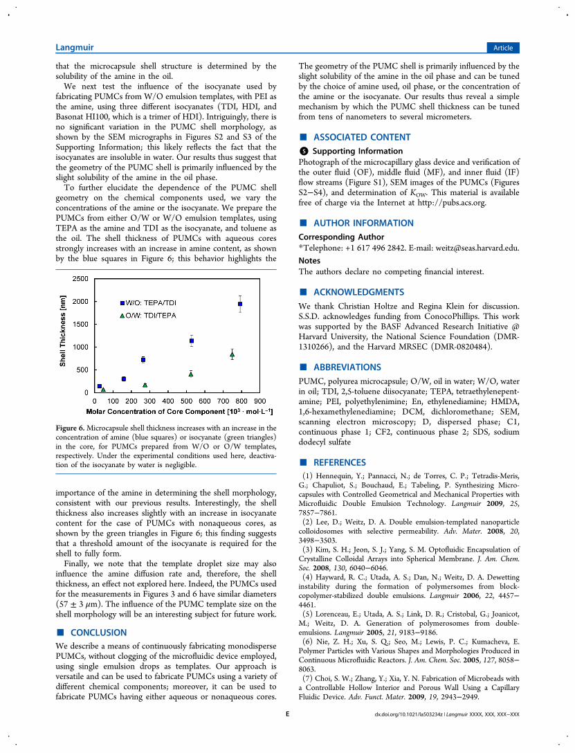
geometry on the chemical components used, we vary theconcentrations of the amine or the isocyanate. We prepare thePUMCs from either O/W or W/O emulsion templates, usingTEPA as the amine and TDI as the isocyanate, and toluene asthe oil. The shell thickness of PUMCs with aqueous coresstrongly increases with an increase in amine content, as shownby the blue squares in Figure 6; this behavior highlights the
importance of the amine in determining the shell morphology,consistent with our previous results. Interestingly, the shellthickness also increases slightly with an increase in isocyanatecontent for the case of PUMCs with nonaqueous cores, asshown by the green triangles in Figure 6; this finding suggeststhat a threshold amount of the isocyanate is required for theshell to fully form.Finally, we note that the template droplet size may also
influence the amine diffusion rate and, therefore, the shellthickness, an effect not explored here. Indeed, the PUMCs usedfor the measurements in Figures 3 and 6 have similar diameters(57 ± 3 μm). The influence of the PUMC template size on theshell morphology will be an interesting subject for future work.
■ CONCLUSIONWe describe a means of continuously fabricating monodispersePUMCs, without clogging of the microfluidic device employed,using single emulsion drops as templates. Our approach isversatile and can be used to fabricate PUMCs using a variety ofdifferent chemical components; moreover, it can be used tofabricate PUMCs having either aqueous or nonaqueous cores.
The geometry of the PUMC shell is primarily influenced by theslight solubility of the amine in the oil phase and can be tunedby the choice of amine used, oil phase, or the concentration ofthe amine or the isocyanate. Our results thus reveal a simplemechanism by which the PUMC shell thickness can be tunedfrom tens of nanometers to several micrometers.
■ ASSOCIATED CONTENT*S Supporting InformationPhotograph of the microcapillary glass device and verification ofthe outer fluid (OF), middle fluid (MF), and inner fluid (IF)flow streams (Figure S1), SEM images of the PUMCs (FiguresS2−S4), and determination of KOW. This material is availablefree of charge via the Internet at http://pubs.acs.org.
■ AUTHOR INFORMATIONCorresponding Author*Telephone: +1 617 496 2842. E-mail: [email protected].
NotesThe authors declare no competing financial interest.
■ ACKNOWLEDGMENTSWe thank Christian Holtze and Regina Klein for discussion.S.S.D. acknowledges funding from ConocoPhillips. This workwas supported by the BASF Advanced Research Initiative @Harvard University, the National Science Foundation (DMR-1310266), and the Harvard MRSEC (DMR-0820484).
■ ABBREVIATIONSPUMC, polyurea microcapsule; O/W, oil in water; W/O, waterin oil; TDI, 2,5-toluene diisocyanate; TEPA, tetraethylenepent-amine; PEI, polyethylenimine; En, ethylenediamine; HMDA,1,6-hexamethylenediamine; DCM, dichloromethane; SEM,scanning electron microscopy; D, dispersed phase; C1,continuous phase 1; CF2, continuous phase 2; SDS, sodiumdodecyl sulfate
■ REFERENCES(1) Hennequin, Y.; Pannacci, N.; de Torres, C. P.; Tetradis-Meris,G.; Chapuliot, S.; Bouchaud, E.; Tabeling, P. Synthesizing Micro-capsules with Controlled Geometrical and Mechanical Properties withMicrofluidic Double Emulsion Technology. Langmuir 2009, 25,7857−7861.(2) Lee, D.; Weitz, D. A. Double emulsion-templated nanoparticlecolloidosomes with selective permeability. Adv. Mater. 2008, 20,3498−3503.(3) Kim, S. H.; Jeon, S. J.; Yang, S. M. Optofluidic Encapsulation ofCrystalline Colloidal Arrays into Spherical Membrane. J. Am. Chem.Soc. 2008, 130, 6040−6046.(4) Hayward, R. C.; Utada, A. S.; Dan, N.; Weitz, D. A. Dewettinginstability during the formation of polymersomes from block-copolymer-stabilized double emulsions. Langmuir 2006, 22, 4457−4461.(5) Lorenceau, E.; Utada, A. S.; Link, D. R.; Cristobal, G.; Joanicot,M.; Weitz, D. A. Generation of polymerosomes from double-emulsions. Langmuir 2005, 21, 9183−9186.(6) Nie, Z. H.; Xu, S. Q.; Seo, M.; Lewis, P. C.; Kumacheva, E.Polymer Particles with Various Shapes and Morphologies Produced inContinuous Microfluidic Reactors. J. Am. Chem. Soc. 2005, 127, 8058−8063.(7) Choi, S. W.; Zhang, Y.; Xia, Y. N. Fabrication of Microbeads witha Controllable Hollow Interior and Porous Wall Using a CapillaryFluidic Device. Adv. Funct. Mater. 2009, 19, 2943−2949.
Figure 6.Microcapsule shell thickness increases with an increase in theconcentration of amine (blue squares) or isocyanate (green triangles)in the core, for PUMCs prepared from W/O or O/W templates,respectively. Under the experimental conditions used here, deactiva-tion of the isocyanate by water is negligible.
Langmuir Article
dx.doi.org/10.1021/la503234z | Langmuir XXXX, XXX, XXX−XXXE
(8) Anna, S. L.; Bontoux, N.; Stone, H. A. Formation of dispersionsusing “flow focusing” in microchannels. Appl. Phys. Lett. 2003, 82 (3),364−366.(9) Thorsen, T.; Roberts, R. W.; Arnold, F. H.; Quake, S. R. Dynamicpattern formation in a vesicle-generating microfluidic device. Phys. Rev.Lett. 2001, 86, 4163−4166.(10) Ota, S.; Yoshizawa, S.; Takeuchi, S. Microfluidic formation ofmonodisperse, cell-sized, and unilamellar vesicles. Angew. Chem., Int.Ed. 2009, 48, 6533−6537.(11) Xu, S.; Nie, Z.; Seo, M.; Lewis, P.; Kumacheva, E.; Stone, H. A.;Garstecki, P.; Weibel, D. B.; Gitlin, I.; Whitesides, G. M. Generation ofmonodisperse particles by using microfluidics: Control over size,shape, and composition. Angew. Chem., Int. Ed. 2005, 44, 3799.(12) Choi, S. W.; Cheong, I. W.; Kim, J. H.; Xia, Y. Preparation ofUniform Microspheres Using a Simple Fluidic Device and TheirCrystallization into Close-Packed Lattices. Small 2009, 5, 454−459.(13) Okushima, S.; Nisisako, T.; Torii, T.; Higuchi, T. Controlledproduction of monodisperse double emulsions by two-step dropletbreakup in microfluidic devices. Langmuir 2004, 20, 9905−9908.(14) Dendukuri, D.; Tsoi, K.; Hatton, T. A.; Doyle, P. S. Controlledsynthesis of nonspherical microparticles using microfluidics. Langmuir2005, 21, 2113−2116.(15) Hwang, D. K.; Dendukuri, D.; Doyle, P. S. Microfluidic-basedsynthesis of non-spherical magnetic hydrogel microparticles. Lab Chip2008, 8, 1640−1647.(16) Nie, Z. H.; Li, W.; Seo, M.; Xu, S. Q.; Kumacheva, E. Janus andternary particles generated by microfluidic synthesis: Design, synthesis,and self-assembly. J. Am. Chem. Soc. 2006, 128, 9408−9412.(17) Nisisako, T.; Torii, T. Microfluidic large-scale integration on achip for mass production of monodisperse droplets and particles. LabChip 2008, 8, 287−293.(18) Dispinar, T.; Colrad, C. A. L.; Du Prez, F. E. Polyureamicrocapsules with a photocleavable shell: UV-triggered release.Polym. Chem. 2013, 4, 763−772.(19) Ouali, L.; Benczedi, D. Polyurethane and Polyurea Micro-capsules. U.S. Patent 20080206291 A1, 2008.(20) Schwartz, L.; Wolf, D.; Markus, A.; Wybraniec, S.; Wiesman, Z.Controlled-Release Systems for the Delivery of Cyromazine intoWater Surface. J. Agric. Food Chem. 2003, 51, 5972−5976.(21) Scarfato, P.; Avallone, E.; Iannelli, P.; De Feo, V.; Acierno, D.Synthesis and characterization of polyurea microcapsules containingessential oils with antigerminative activity. J. Appl. Polym. Sci. 2007,105, 3568−3577.(22) Bremeyer, N.; Ley, S. V.; Ramarao, C.; Shirley, I. M.; Smith, S.C. Palladium Acetate in Polyurea Microcapsules: A Recoverable andReusable Catalyst for Hydrogenations. Synlett 2002, 11, 1843−1844.(23) Yu, J. Q.; Wu, H. C.; Ramarao, C.; Spencer, J. B.; Ley, S. V.Transfer hydrogenation using recyclable polyurea-encapsulatedpalladium: Efficient and chemoselective reduction of aryl ketones.Chem. Commun. 2003, 678−679.(24) Siu, J.; Baxendale, I. R.; Ley, S. V. Microwave assistedLeimgruber−Batcho reaction for the preparation of indoles, azaindolesand pyrroylquinolines. Org. Biomol. Chem. 2004, 2, 160−167.(25) Baxendale, I. R.; Griffiths-Jones, C. M.; Ley, S. V.; Tranmer, G.K. Microwave-Assisted Suzuki Coupling Reactions with an Encapsu-lated Palladium Catalyst for Batch and Continuous-Flow Trans-formations. Chem.Eur. J. 2006, 12, 4407−4416.(26) Broadwater, S. J.; McQuade, D. T. Investigating PdEnCatCatalysis. J. Org. Chem. 2006, 71, 2131−2134.(27) Yang, J. L.; Keller, M. W.; Moore, J. S.; White, S. R.; Sottos, N.R. Microencapsulation of Isocyanates for Self-Healing Polymers.Macromolecules 2008, 41, 9650−9655.(28) Utada, A. S.; Lorenceau, E.; Link, D. R.; Kaplan, P. D.; Stone, H.A.; Weitz, D. A. Monodisperse double emulsions generated from amicrocapillary device. Science 2005, 308, 537−541.(29) Shum, H. C.; Varnell, J.; Weitz, D. A. Microfluidic fabrication ofwater-in-water (w/w) jets and emulsions. Biomicrofluidics 2012, 6,012808.
(30) Kim, S.-H.; Kim, J. W.; Cho, J. C.; Weitz, D. A. Double-emulsion drops with ultra-thin shells for capsule templates. Lab Chip2011, 11, 3162−3166.(31) Kim, S. H.; Weitz, D. A. One-step emulsification of multipleconcentric shells with capillary microfluidic devices. Angew. Chem., Int.Ed. 2011, 123, 8731−8734.(32) Vladisavljevic, G. T.; Duncanson, W. J.; Shum, H. C.; Weitz, D.A. Emulsion templating of poly(lactic acid) particles: Dropletformation behavior. Langmuir 2012, 28, 12948−12954.(33) Leo, A.; Hansch, C.; Elkins, D. Partitioning coefficients and theiruses. Chem. Rev. 1971, 71, 525−616.
Langmuir Article
dx.doi.org/10.1021/la503234z | Langmuir XXXX, XXX, XXX−XXXF