Controlling Snow and Ice on the Morgantówn People Mover...
7
Controlling Snow and Ice on the Morgantówn People Mover System Philip H. Morgan, U. S. Department of Transportation This paper describes how the Morgantown People Mover has become the first automated guideway system in an urban area which is fully operational throughout winter. Unique operational methods and mechanical features of the vehicle have been developed to assure adequate tire traction, consistent steering and switching perfonnance, and reliable power collection during their severe winter weather. Operating costs and the trends in winter operational reliability show the continuing improvement as system operating experience is accumulated. the West Virginia University. OCXISTING D%AINTENANCL STATION / •EXISTING PaT STATION IC EXISTING GUIDEWAY - DOWNTOWN 'CMPUS ENGI The Morgantown system was the first fully automated people mover to be operational in an urban and university environment. The Urban Mass Transportation Administration of the Department of Transportation built the system to demonstrate and evaluate the benefits of automated guideway transit technology. The prime contractor for the system was the Boeing Aerospace Company. UMTA selected Morgantown as the site because it furthered the interests of both the West Virginia University (WVU) and UMTA. The West Virginia University wanted a people mover system to solve its inter-campus transportation problems while UMTA wanted a site sufficiently urban that a meaningful evaluation of the system for potential application to other cities could be made. The system uses driverless, electrically-powered vehicles controlled by computers and provides direct, non-stop service from origin to destination for West Virginia University students and residents of Morgantown. The present system consists of 5.4 miles of single lane guideway with grades up to 10%, three stations, a maintenance facility and central control complex, and a fleet of 45 rubber-tired 21-passenger vehicles (Figure 1). Initial test operation of the system took place in October, 1972. Revenue passenger-carrying operations began in October, 1975. Since then, more than 4.5 million passengers have been carried without an operations-related serious injury or fatality to either passengers or operating and maintenance personnel. The system is now owned and operated by FIGURE 1. MPRT ROUTE LAYOUT CONNECTING THREE WVU CNIPUSES AND MAIN BUSINESS DISTRICT There is a great deal to be learned from how the Morgantown system has been made operational in winter because the Morgantown environment is quite variable and subjects the People Mover to extremes of temperature, snowfall, sleet, and wind, more severe than those of any other operating Automated Guideway Transit (AGT) Systems. Typical snowfall in Morgantown is 25-75mm (1 to 3 inches) on ten days during each December and January. Trace amounts occur, perhaps, twice as often. On Figure 2, the low and high temperaturesare shown for December and January of the three winters during which the Morgantown System has been operated. It has not been unusual to have a week at a time in which temperatures stay below freezing or in which low temperatures may hover between 0 °C and -10°C. During the rest of the winter the temperature drops below freezing almost every night causing melted snow to refreeze and frequent formation of frost. The subject of controlling snow and ice on the Morgantown system can be divided into four areas: 343
Transcript of Controlling Snow and Ice on the Morgantówn People Mover...

Controlling Snow and Ice on the Morgantówn People Mover System Philip H. Morgan, U. S. Department of Transportation
This paper describes how the Morgantown People Mover has become the first automated guideway system in an urban area which is fully operational throughout winter. Unique operational methods and mechanical features of the vehicle have been developed to assure adequate tire traction, consistent steering and switching perfonnance, and reliable power collection during their severe winter weather. Operating costs and the trends in winter operational reliability show the continuing improvement as system operating experience is accumulated.
the West Virginia University.
OCXISTING D%AINTENANCL STATION
/ •EXISTING PaT STATION
IC EXISTING GUIDEWAY
- DOWNTOWN 'CMPUS
ENGI
The Morgantown system was the first fully automated people mover to be operational in an urban and university environment. The Urban Mass Transportation Administration of the Department of Transportation built the system to demonstrate and evaluate the benefits of automated guideway transit technology. The prime contractor for the system was the Boeing Aerospace Company. UMTA selected Morgantown as the site because it furthered the interests of both the West Virginia University (WVU) and UMTA. The West Virginia University wanted a people mover system to solve its inter-campus transportation problems while UMTA wanted a site sufficiently urban that a meaningful evaluation of the system for potential application to other cities could be made.
The system uses driverless, electrically-powered vehicles controlled by computers and provides direct, non-stop service from origin to destination for West Virginia University students and residents of Morgantown. The present system consists of 5.4 miles of single lane guideway with grades up to 10%, three stations, a maintenance facility and central control complex, and a fleet of 45 rubber-tired 21-passenger vehicles (Figure 1).
Initial test operation of the system took place in October, 1972. Revenue passenger-carrying operations began in October, 1975. Since then, more than 4.5 million passengers have been carried without an operations-related serious injury or fatality to either passengers or operating and maintenance personnel. The system is now owned and operated by
FIGURE 1. MPRT ROUTE LAYOUT CONNECTING THREE WVU CNIPUSES AND MAIN BUSINESS DISTRICT
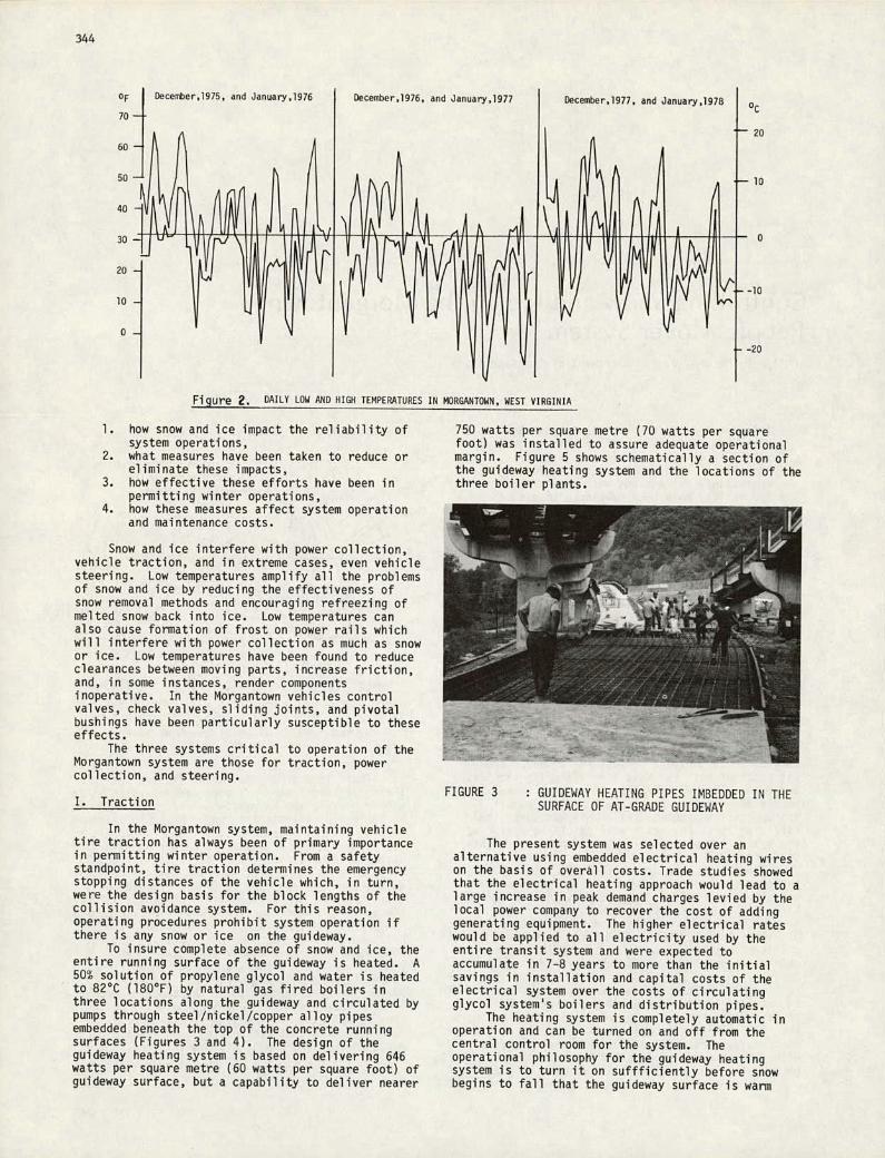
There is a great deal to be learned from how the Morgantown system has been made operational in winter because the Morgantown environment is quite variable and subjects the People Mover to extremes of temperature, snowfall, sleet, and wind, more severe than those of any other operating Automated Guideway Transit (AGT) Systems. Typical snowfall in Morgantown is 25-75mm (1 to 3 inches) on ten days during each December and January. Trace amounts occur, perhaps, twice as often. On Figure 2, the low and high temperaturesare shown for December and January of the three winters during which the Morgantown System has been operated. It has not been unusual to have a week at a time in which temperatures stay below freezing or in which low temperatures may hover between 0°C and -10°C. During the rest of the winter the temperature drops below freezing almost every night causing melted snow to refreeze and frequent formation of frost.
The subject of controlling snow and ice on the Morgantown system can be divided into four areas:
343
-
:-:.-
OF
70
60
50
40
30
20
10
oc
20
10
10
.20
Figure 2. DAILY LOW AND HIGH TEMPERATURES IN MORGANTOWN. WEST VIRGINIA
how snow and ice impact the reliability of system operations, what measures have been taken to reduce or eliminate these impacts, how effective these efforts have been in permitting winter operations, how these measures affect system operation and maintenance costs.
Snow and ice interfere with power collection, vehicle traction, and in extreme cases, even vehicle steering. Low temperatures amplify all the problems of snow and ice by reducing the effectiveness of snow removal methods and encouraging refreezing of melted snow back into ice. Low temperatures can also cause formation of frost on power rails which will interfere with power collection as much as snow or ice. Low temperatures have been found to reduce clearances between moving parts, increase friction, and, in some instances, render components inoperative. In the Morgantown vehicles control valves, check valves, sliding joints, and pivotal bushings have been particularly susceptible to these effects.
The three systems critical to operation of the Morgantown system are those for traction, power collection, and steering.
I. Traction
In the Morgantown system, maintaining vehicle tire traction has always been of primary importance in permitting winter operation. From a safety standpoint, tire traction determines the emergency stopping distances of the vehicle which, in turn, were the design basis for the block lengths of the collision avoidance system. For this reason, operating procedures prohibit system operation if there is any snow or ice on the guideway.
To insure complete absence of snow and ice, the entire running surface of the guideway is heated. A 50% solution of propylene glycol and water is heated to 82°C (180°F) by natural gas fired boilers in three locations along the guideway and circulated by pumps through steel/nickel/copper alloy pipes embedded beneath the top of the concrete running surfaces (Figures 3 and 4). The design of the guideway heating system is based on delivering 646 watts per square metre (60 watts per square foot) of guideway surface, but a capability to deliver nearer
750 watts per square metre (70 watts per square foot) was installed to assure adequate operational margin. Figure 5 shows schematically a section of the guideway heating system and the locations of the three boiler plants.
FIGURE 3 : GUIDEWAY HEATING PIPES IMBEDDED IN THE SURFACE OF AT-GRADE GUIDEWAY
The present system was selected over an alternative using embedded electrical heating wires on the basis of overall costs. Trade studies showed that the electrical heating approach would lead to large increase in peak demand charges levied by the local power company to recover the cost of adding generating equipment. The higher electrical rates would be applied to all electricity used by the entire transit system and were expected to accumulate in 7-8 years to more than the initial savings in installation and capital costs of the electrical system over the costs of circulating glycol system's boilers and distribution pipes.
The heating system is completely automatic in operation and can be turned on and off from the central control room for the system. The operational philosophy for the guideway heating system is to turn it on suffficiently before snow begins to fall that the guideway surface is warm
344

0 AnlbiOfll Tenp,aInr. in
A -12 2(10) C -3.9)25)
B -7.5(18) D 1.7(35)
12-4 -----
12
345
FIGURE 4 : GUIDEWAY HEATING PIPES IMBEDDED ONLY IN RUNNING PADS OF ELEVATED GUIDEWAY
Ia - 11T II
- 1'3—.-------
FIGURE 5: TYPICAL GUIDEWAY HEATING SYSTEM BOILER PLANT
enough to melt snow on contact and without any accumulation. As shown in Figure 6, the entire guideway, heating solution, and distribution piping requires about 2 hours to be heated from an ambient temperature of -7°C (20°F) to the melting point of snow above 0°C (32°F.) If the guideway has not been warmed sufficiently to melt snow as fast as it falls, the heating system becomes far less effective in melting the snow. The melted snow doesnt run off freely but, rather, is retained as slush and insulates the unmelted snow from the warm guideway surface. Then part of the heat output from the guideway is wasted in raising the temperature of the captive water.
Accurate forecasting of snow, freezing rain, etc., is necessary for timely use of the guideway heating system and to preclude operating the heating system unnecesarily. WVU obtains weather forecasts from a private weather service specializing in their location and relies heavily on their forecasts of snow or sudden drops in temperatures in planning the operation of the heating system and other strategies to combat effects of adverse weather. The guideway heating system has been extremely effective; the People Mover system has never failed to operate because of snow falling faster than the guideway heating system could melt it.
I I I I fl 2 4 8 8
How,, All,, G1,deway Honling SIlOop
FIGURE 6: GUIDEWAY SURFACE WARN-UP TIME
II. Power Collection
The Morgantown vehicle is electrically powered by 575 volt, 3 phase, 60 hertz a.c. Interruption of power on any phase for more than 1/2 second will cause the vehicle to be stopped by service brakes. In turn, all trailing vehicles would also be stopped. The principal causes of power loss have been snow or ice on the power rail and brushes binding in the collector.
As shown in Figures 7 and 8, the power rails are arranged in a V-shaped Acrylonitrile-Butadiene-. Styrene (ABS) plastic carrier and the collector holds brushes in a matching array. Rubber wheels at
ASS PLASTIC CARAIER
PPER BUS BUSMS
£80 VIE9 "5°
P0858 MI I.
LPOWES COLLECTOR —SINTERED COPPER SRUSHES(2 PER PKASE)
WHEEL (S PLACES) VEHICLE POWER COLLECTOR SIDE VIEW FIGURE 7: PRESENT POWER RAIL AND COLLECTOR

I
I -4...--
346
FIGURE 8: PRESENT POWER RAIL
each end of the collector body align the collector with the ABS carrier and support the collector against the force applied by the pneumatic positioning arm. Two brushes per phase are provided to minimize arcing at power rail joints. To prevent brushes from binding in the collector, the collectors have been modified by the addition of stainless steel liners to the brush cavity and 15 watt/brush heater wires to prevent icing (Figure 9).
To prevent ice from forming on the power rail,
r _ FIGURE 10: DE—ICING VEHICLE WITH ROTATING BRUSH
FIGURE 9: PRESENT POWER COLLECTOR/HEATING WIRES
procedures and equipment for applying hot 25% ethylene glycol and water solution have been developed by WVU. During snowfall or freezi.ng rain, two or three regular vehicles are equipped for spraying glycol solution and operated along the entire guideway at 20 to 30 minute intervals. Their equipment includes two 208 litre (55 gallon) drums of 60°C (140°F) glycol solution, a 689.5kPa (100 psig) pump, and spray nozzles outside the vehicle aimed to cover the power rail envelope. This has been found sufficient to prevent snow or ice accumulation on the rails. If vehicle stoppages should prevent use of automated spray vehicles or if unexpected snowfall should occur, snow or ice may accumulate on the power rails. Accumulations of snow can be removed from the power rail by towing a special deicing vehicle along the unpowered guideway with a jeep. This deicing vehicle is unpowered and has had its on-board computer, environmental control equipment, and propulsion system removed and has been equipped with five 208 litre (55 gallon) drums of heated glycol solution, a portable electrical generator, fluid pump, spray nozzles, and a motor-driven rotating brush to mechanically dislodge snow and ice (Figure 10).
The application of glycol to the power rails leads to a gummy residue and gradual accumulation of abrasive particles from the brushes as they wear.

347
mom
FIGURE 11: PhASE II POWER RAIL
If not removed, the glycol residue soon leads to accelerated brush wear rates, electrical leakage problems, and reduced power collector performance. For thee reasons, rails are routinely washed at the first opportunity after snowing and icing conditions subside. The cleaning is done with the special deicing vehicle equipped with drums of plain water and the rotating bristle brush.
In September 1976, IJMTA approved a Capital Grant to the West Virginia Board of Regents for the Phase II expansion of the Morgantown system and the incorporation of some technical improvements. One of the most significant improvements being made is the replacement of the present power rail with a new one which can be heated. The new power rail assembly (Figure 11) features rails arranged in a vertical array to increase the leakage path between phases, stainless steel contact surfaces, aluminum conductor, a non-flammable Poly Vinyl Chloride (PVC) insulating carrier, and integral heating wires. It is expected that the 45.7 watt per metre (15 watt per foot) heating on each rail will be sufficient to remove frost and to prevent snow accumulation without having to apply the glycol solution. Also, the Phase II power collector (Figure 12) will include provision for heating. The entire pneumatic deployemnt system for the power collector has been eliminated and replaced by an outward spring-loaded pantograph to apply collector brush pressure to the power rail.
One note on the use of glycol deicing solutions: they are not compatible with salt deicing chemicals. When these chemicals mix with glycol, the resulting solution is highly conductive of electricity. Phase-to-phase arcing can cause damaged power collectors and rails, and poses a fire safety hazard in the presence of combustible materials. In Morgantown, though salt is not used on the guideway, the city uses it on the roads. As a result, fiberglass panels had to be installed by WVIJ to prevent deicing salt applied to a nearby highway from being splashed by passing cars onto the system guideway and power rail.
FIGURE 12: PHASE II POWER COLLECTOR ASSEMBLY
III. Steering
Another significant area of winter weather impact is the steering and switching systems of the vehicle (Figure 13). The vehicle steers by following a rail along the left or right side of the guideway. Guidewheels at the front of the vehicle are applied against the rail with nominal force of 800 newton (180 lbs.) The linkage to which the guidewheels are attached moderates the hydraulic pressure counteracting the force of a 1780 newton (400 lb.) bias spring to maintain the 800 newton (180 lb.) force against the guidewheels. The 1780 newton (400 lb.) spring causes the movement of the steering wheels and linkage until the 800 newton (180 lb.) force has been established. Switching from guideway into station ramping is accomplished by hydraulically repositioning the bias spring such that the steering force is removed from the left side and re-applied to the right side.
WIK (CL
lflDI UIL (UE)
FIGURE 13: PRESENT STEERING AND SWITCHING SYSTEM

$60
$40 0511151.,
Costs (thossono,)
$20
$10
TT
ç.: ___
FIGURE 15: HEATED BIAS SWITCHING ACTUATOR FIGURE 18: GUIDEWAY HEATING SYSTEM UTILITIES
Oocer Jonio.ry February
348
Cold temperatures increase frictional resistance in the steering linkage bushings and reduce the quickness with which steering corrections occur. The internal clearances of hydraulic components, particularly the steering control valve, diminish and the valves operate more slowly or bind. The principal remedy for high friction in linkage bushings has been a change to water-insoluble greases which are not as quickly displaced by the action of turbulent air with entrained water passing through the chassis.
The binding of steering control valves, bias actuators, preload springs, and sliding joints in the guide axle has been largely eliminated by local heating with strip heaters (Figures 14 and 15). Altogether, these measures have been found effective in maintaining system operability down to -15°C (5°F.)
FIGURE 14: ELECTRICALLY HEATED GUIDE AXLE
I !M•I I I I1I/ . S S S Ii!.
FIGURE 16: PHASE II STEERING AND SWITCHING SYSTEM
severe weather, the vehicle was taken out of service to remove ice accumulated on the chassis which would physically obstruct motion of the steering linkage. Cold chamber testing has demonstrated that the all-mechanical steering system is operable down to -34.4°C (-300F.)
IV. System Reliability and Costs
Efforts to increase the operational reliability of the Morgantown system in winter weather have
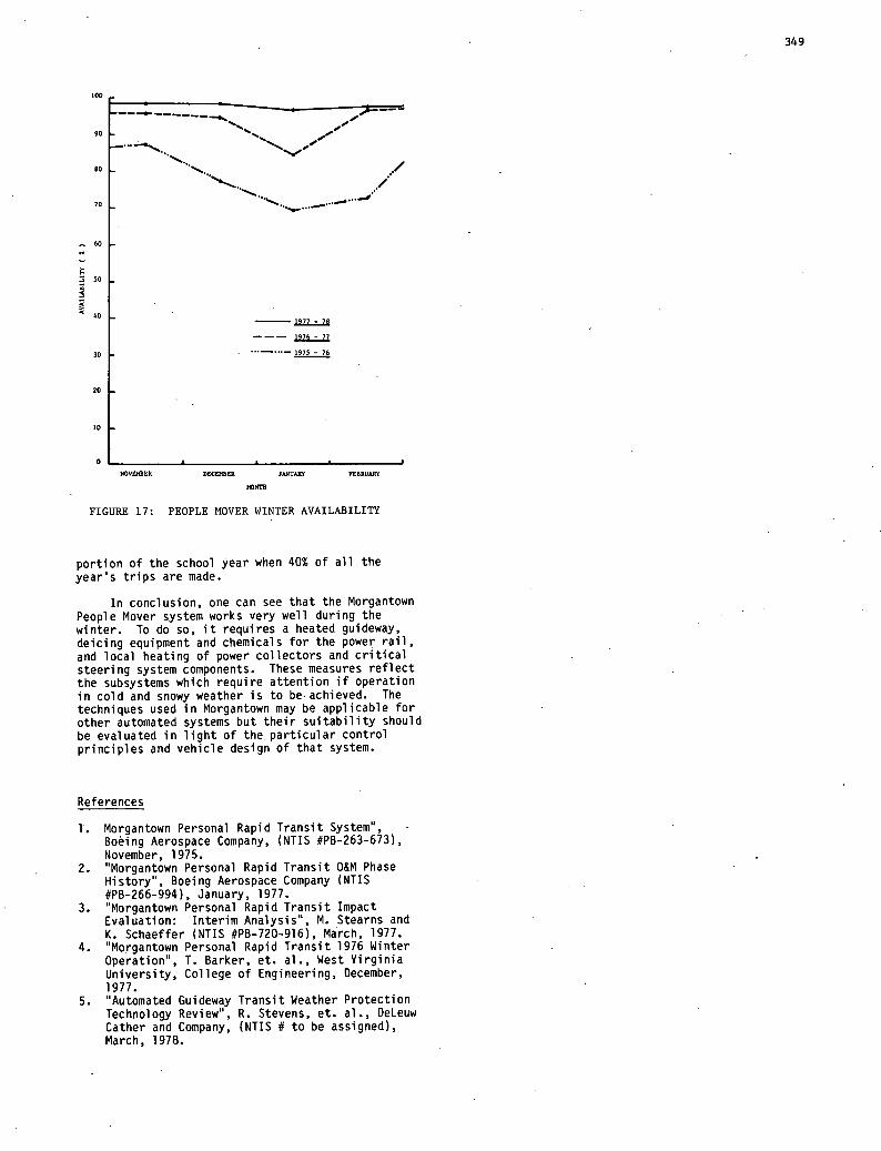
been reflected by dramatic improvement in the availability statistics over the last three winters (Figure 17). The average availability for December, January, and February has improved each year, from 73.5% in 1975-76 to 92.1% in 1976-77 to 97.5% in 1977. It is also noteworthy that not a single day of operation was cancelled due to adverse weather during the winter of 1977-78.
Redesign of the steering system in Phase II (Figure 16) has eliminated the hydraulic steering contol valve and replaced most bushings at steering linkage joints with low temperature, anti-friction bearings. The new steering system has been instal-led on a vehicle and operated during last winter. On one occasion, this vehicle operated without maintenance and without difficulty throughout a ten inch Snowstorm. After twelve hours operation, in
The costs of natural gas and electricity for the guideway heating system are shown in Figure 18 for the last two winters in Morgantown. In total, they are less than 6% of the annual operating costs of the system. This seems a reasonable expense to insure that the system operates as any transit system should, i.e., every day that it is scheduled. In the case of the University, the guideway heating system allows reliable system operations during the
100
90
80
70
60
50
3
40
30
20
10
N0VEBER DEC080ER JAJ47JAIY FEBRUARY
FIGURE 17: PEOPLE MOVER WINTER AVAILABILITY
portion of the school year when 40% of all the year's trips are made.
In conclusion, one can see that the Morgantown People Mover system works very well during the winter. To do so, it requires a heated guideway, deicing equipment and chemicals for the power rail, and local heating of power collectors and critical steering system components. These measures reflect the subsystems which require attention if operation in cold and snowy weather is to beachieved. The techniques used in Morgantown may be applicable for other automated systems but their suitability should be evaluated in light of the particular control principles and vehicle design of that system.
References
Morgantown Personal Rapid Transit System", Boeing Aerospace Company, (NTIS #PB-263-673), November, 1975. "Morgantown Personal Rapid Transit 0&M Phase History', Boeing Aerospace Company (NTIS #PB-266-994), January, 1977. 'Morgantown Personal Rapid Transit Impact Evaluation: Interim Analysis", ft. Stearns and K. Schaeffer (NTIS #PB-720-.916), March, 1977. 'Morgantown Personal Rapid Transit 1976 Winter Operation', T. Barker, et. al., West Virginia University, College of Engineering, December, 1977. "Automated Guideway Transit Weather Protection Technology Review', R. Stevens, et. al., DeLeuw Cather and Company, (NTIS # to be assigned), March, 1978.
349