Controller Design for a Delta Robot Using Lagrangian ...
13
Controller Design for a Delta Robot Using Lagrangian Multipliers Fu-Shin Lee ( [email protected] ) Huafan University Chen-I Lin Wuyi University Research Article Keywords: Lagrangian multipliers, Delta robot, Controller design, novelty, robot mechanisms Posted Date: September 23rd, 2021 DOI: https://doi.org/10.21203/rs.3.rs-898296/v1 License: This work is licensed under a Creative Commons Attribution 4.0 International License. Read Full License
Transcript of Controller Design for a Delta Robot Using Lagrangian ...

Controller Design for a Delta Robot UsingLagrangian MultipliersFu-Shin Lee ( [email protected] )
Huafan UniversityChen-I Lin
Wuyi University
Research Article
Keywords: Lagrangian multipliers, Delta robot, Controller design, novelty, robot mechanisms
Posted Date: September 23rd, 2021
DOI: https://doi.org/10.21203/rs.3.rs-898296/v1
License: This work is licensed under a Creative Commons Attribution 4.0 International License. Read Full License
Controller design for a Delta robot
using Lagrangian multipliers Fu-Shin Lee 1, *
Chen-I Lin 2 1 Mechatronic Engineering Institute, Huafan University, Taipei 22301, Taiwan. 2 College of Mechanical and Electrical Engineering, Wuyi University, Wuyishan, 354300, China. * [email protected]
The novelty of this research is that the study utilizes Lagrangian multipliers
for an articulated close-chain robot mechanism as time-varying states to
augment an energy-based Lagrangian dynamic model, and the strategy
facilitates the system computations while satisfying the forward/inverse
dynamics and mechanism constraints simultaneously for the close-chained
robot. Then, this article develops a controller based upon the augmented
dynamics model for the Delta robot mechanism and drives its moving
platform to track prescribed trajectories in space. As a result, the simulation
results validate the effectiveness of the augmented system model in
undertaking complex dynamics of close-chained robot mechanisms.
The dynamics of articulated closed-chain mechanisms, such as Delta robots, are changeling
to undertake due to their complexity in mechanism constraints. This research uses Lagrangian
multipliers in an energy-based approach as augmented time-varying states and effectively
develops a controller to track prescribed trajectories in space.
Nowadays, Delta robots handle various objects because their parallel or articulated design
facilitates the mechanisms to move rapidly and accurately, and their robust structures assist
deployments for various highspeed tasks in the manufacturing and food processing industries.
Delta robot structures are complex electromechanical systems due to their parallel/articulated
mechanisms and nonlinear characteristics. Conventional controller design usually attempts
various structural geometries, mechanism materials, and controller means to achieve
acceptable Delta robot performances, such as stability and accuracy. For prescribing
acceptable tracking error bounds for a Delta robot manipulator, some researchers developed
hybrid nonlinear controllers to asymptotically converge the tracking errors to zero1. Others
proposed nonlinear PD (proportional-derivative) controllers to manage coupling effects and
external disturbances for high-precision trajectory tracking2.
Researchers typically investigate Delta robot performances by studying forward/inverse
kinematics, forward/inverse dynamics, energy-based analyses, and other theoretical
approaches3. For example, researchers derived an energy-based dynamic model using
kinematic relations for the Delta robot mechanisms and solved the inverse dynamics equations
to investigate different serial-mechanism influences4. Other researchers transformed a Delta
highspeed manipulator model into a SimMechanics development platform, and that study
simulated the manipulator's motion to design the corresponding controllers5.
Since the last decade, applications in the automation field have demanded high-speed
positioning accuracy for Delta robot manipulators, and disturbance rejections and error
compensations have become critical issues6. Some researchers proposed sliding mode control
approaches based on Delta robot dynamics, and the object is to track given reference
trajectories with uncertain model parameters for that manipulator7. By employing kinematics
and dynamics with feedback for a Delta robot manipulator, others presented simple model-
based control schemes to evaluate applied driving torques, and their schemes compensated
the errors to fulfill the closed-loop control requirements8. Besides, other researchers
developed nonlinear controllers using structural optimization methods and symbolic
adaptation algorithms to track prescribed trajectories9.
Delta robot applications also demand compact mechanisms with lightweight controllers
for the industry10, and embedded electronics using wireless interfacing become mandatory.
Some researchers utilized an FPGA (Field Programmable Gate Array) device as dedicated
hardware to provide a closed-loop servo control system, which exercises a Delta robot's
kinematics equations to perform fast and accurate positioning11. In addition, other researchers

designed two controllers to ensure stability and performance of a Delta robot closed-loop
system, and that study embedded the control algorithms into a myRIO hardware device
through the LabVIEW deployments12.
Researchers recently employed an adaptive neural network controller for a Delta robot to
track prescribed trajectories, and that study implemented an adaptive artificial neural network
for online training13. In addition, other researchers applied a model-free iterative learning
control strategy (ILC) to a Delta robot manipulator, which subjects to external disturbances
for tracking nonrepetitive trajectories14.
Literatures typically formulate equations of motion for simple multi-body systems using
the energy-based Lagrangian formulation, and employing generalized coordinate variables is
sufficient to describe the dynamics of the closed systems completely15,16. For example,
researchers established a singularity-free dynamic model using an augmented Lagrangian or
Hamiltonian formulation to derive the inverse dynamic equations for a Delta robot within an
object-oriented modeling framework 17. Others also presented a closed-form dynamics model
using a Lagrangian formulation for a Delta mechanism in verifications18.
Investigating physical cooperation with multiple manipulators also needs to invite
additional Lagrangian multipliers to satisfy constraint conditions19. Researchers developed a
control scheme using a constrained Lagrangian dynamics and Lagrangian multipliers
formulation for cooperative mechanisms, and the exploited controller assumes both motion
and force demands throughout the derived inverse dynamics models20. Similarly, researchers
formulated inverse kinematics with position and Jacobian analyses for a Delta robot and
analyzed its inverse dynamics with Lagrangian equations to satisfy constraint conditions21,22.
Note that commercial Delta parallel or articulated robots achieve more than 10m/s velocity
and 15g acceleration. Therefore, accuracy and fast dynamics calculation are essential in torque
control for a Delta robot manipulator in high-speed applications. Hence, some researchers
presented studies that simplified dynamics equation matches its dynamic behaviors very well
with ADAMS modeling and simulations23.
With the relevant literature reports, this paper systematically reformulates the equations
of motions for a Delta robot, and the research develops a novel approach to design a controller
for evaluating the Delta robot performances. Then, this paper presents a simplified system
modeling for the Delta robot complex dynamics, in which the model employs the Lagrangian
equations for the Delta mechanism and manages the inverse dynamic equations and
mechanical constraint equations. Finally, the research utilizes the developed Delta robot
dynamics model to apply PID weight parameters and torque control techniques for evaluating
the controllers' robust performance. The strategy employs time-varying Lagrangian
multipliers iteratively to satisfy the mechanical constraints and realize the tracking objects,
while the dynamics model is iteratively refurnishing the time-varying controller. As a result,
the developed approach verifies the controller's effectiveness in tracking given circular
trajectories in space.
This paper organizes the article as section one for introduction, section two for system
descriptions on the Delta robot mechanism and augmented dynamics model formulation using
the Lagrangian multipliers, section three for a nonlinear tracking controller development with
the Lagrangian multipliers embedded, section four for simulations and discussions using the
augmented dynamics model, and finally section 5 for conclusions of the study.
Method
This paper builds a Delta robot model instead of an actual prototype by incorporating the
Lagrangian multipliers into the controller development. It conducts various analyses and
diverse designs to investigate the Delta robot's kinematics and dynamics' physical limits.
Delta Robot mechanisms. The Delta robot comprises a fixed base, three identical
driving links, three parallelograms branched chains, and a moving platform. The mechanism
employs hinges to connect the driving links and the driven branch chains. Another set of
hinges connect the driven branch chains and the moving platform. Three motors fixed on the
upper base drive their corresponding driving links and control the input angles θ1, θ2, and θ3,
respectively. Figure 1 illustrates the articulated Delta robot mechanism.

Figure 1. Delta robot mechanism illustration.
𝑟𝑓: the length of the driving link 𝜃𝑖: the angular displacement of the 𝑖𝑡ℎ driving link 𝑟𝑒: the length of the driven link 𝑓: the distance from 𝑂 to 𝐹𝑖 (the radius of the fixed platform) 𝑒: the distance from 𝐸𝑜 to 𝐸𝑖 (the radius of the movable platform) 𝑚𝑎: the mass of the driving link 𝑚𝑏: the mass of the driven link 𝑚𝑝: the mass of the movable platform 𝐸0(𝑥0, 𝑦0, 𝑧0): coordinates of the movable platform
Precisely, the Delta robot mechanism in Fig. 1 consists of three subsystems: a movable
platform, a fixed platform, and a set of two-link mechanisms. A driving link and a driven link
form one two-link chain mechanism. Three independent DC brushless motors on the fixed
platform drive the three driving links, respectively, with their associated three-driven links,
as shown in Fig. 224. Hence, the three-driven links cooperatively displace the movable
platform. For investigating the movable platform's motions, the research assumes: (i) the
movable platform displaces smoothly; (ii) no slippage occurs between the driving links and
the corresponding driven links. In the following section, this paper uses notations to formulate
constraint equations and dynamic equations regarding the Delta robot.
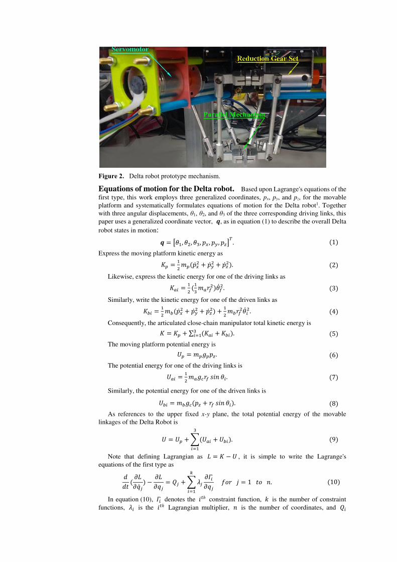
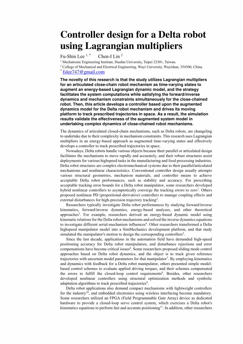
Figure 2. Delta robot prototype mechanism.
Equations of motion for the Delta robot. Based upon Lagrange's equations of the
first type, this work employs three generalized coordinates, px, py, and pz, for the movable
platform and systematically formulates equations of motion for the Delta robot1. Together
with three angular displacements, θ1, θ2, and θ3 of the three corresponding driving links, this
paper uses a generalized coordinate vector, 𝒒, as in equation (1) to describe the overall Delta
robot states in motion:
𝒒 = [𝜃1, 𝜃2, 𝜃3, 𝑝𝑥 , 𝑝𝑦 , 𝑝𝑧]𝑇. (1)
Express the moving platform kinetic energy as
𝐾𝑝 = 12 𝑚𝑝(�̇�𝑥2 + �̇�𝑦2 + �̇�𝑧2). (2)
Likewise, express the kinetic energy for one of the driving links as
𝐾𝑎𝑖 = 12 (13 𝑚𝑎𝑟𝑓2)�̇�𝑓2. (3)
Similarly, write the kinetic energy for one of the driven links as
𝐾𝑏𝑖 = 12 𝑚𝑏(�̇�𝑥2 + �̇�𝑦2 + �̇�𝑧2) + 12 𝑚𝑏𝑟𝑓2�̇�𝑖2. (4)
Consequently, the articulated close-chain manipulator total kinetic energy is
𝐾 = 𝐾𝑝 + ∑ (𝐾𝑎𝑖 + 𝐾𝑏𝑖)3𝑖=1 . (5)
The moving platform potential energy is
𝑈𝑝 = 𝑚𝑝𝑔𝑝𝑝𝑧. (6)
The potential energy for one of the driving links is
𝑈𝑎𝑖 = 12 𝑚𝑎𝑔𝑐𝑟𝑓 𝑠𝑖𝑛 𝜃𝑖. (7)
Similarly, the potential energy for one of the driven links is
𝑈𝑏𝑖 = 𝑚𝑏𝑔𝑐(𝑝𝑧 + 𝑟𝑓 𝑠𝑖𝑛 𝜃𝑖). (8)
As references to the upper fixed x-y plane, the total potential energy of the movable
linkages of the Delta Robot is
𝑈 = 𝑈𝑝 + ∑(𝑈𝑎𝑖 + 𝑈𝑏𝑖)3𝑖=1 . (9)
Note that defining Lagrangian as 𝐿 = 𝐾 − 𝑈 , it is simple to write the Lagrange's
equations of the first type as
𝑑𝑑𝑡 ( 𝜕𝐿𝜕�̇�𝑗) − 𝜕𝐿𝜕𝑞𝑗 = 𝑄𝑗 + ∑ 𝜆𝑗 𝜕𝛤𝑖𝜕𝑞𝑗𝑘
𝑖=1 𝑓𝑜𝑟 𝑗 = 1 𝑡𝑜 𝑛. (10)
In equation (10), 𝛤𝑖 denotes the 𝑖𝑡ℎ constraint function, 𝑘 is the number of constraint
functions, 𝜆𝑖 is the 𝑖𝑡ℎ Lagrangian multiplier, 𝑛 is the number of coordinates, and 𝑄𝑖

represents the 𝑖𝑡ℎ generalized force. Consequently, equation (10) results in 𝑛 equations of
motions in the following general form:
𝐌(𝒒)�̈� + 𝐂(𝒒, �̇�) + 𝐆(𝒒) + 𝐉𝑻 (𝒒)𝝀 = 𝐐. (11)
where 𝝀 is a vector consisting of the Lagrangian multipliers.
For deriving the Lagrangian multipliers, rewrite the above equation as:
2 ∑ 𝜆𝑖(𝑝𝑥 + 𝑒 𝑐𝑜𝑠 𝜑𝑖 − 𝑓 𝑐𝑜𝑠 𝜑𝑖 − 𝑟𝑓 𝑐𝑜𝑠 𝜑𝑖 𝑐𝑜𝑠 𝜃𝑖) = (𝑚𝑝 + 3𝑚𝑏)�̈�𝑥3𝑖=1 . (12)
2 ∑ 𝜆𝑖(𝑝𝑦 + 𝑒 𝑠𝑖𝑛 𝜑𝑖 − 𝑓 𝑠𝑖𝑛 𝜑𝑖 − 𝑟𝑓 𝑠𝑖𝑛 𝜑𝑖 𝑐𝑜𝑠 𝜃𝑖) = (𝑚𝑝 + 3𝑚𝑏)�̈�𝑦3𝑖=1 . (13)
2 ∑ 𝜆𝑖(𝑝𝑧 − 𝑟𝑓 𝑠𝑖𝑛 𝜃𝑖)3𝑖=1 = (𝑚𝑝 + 3𝑚𝑏)�̈�𝑧 + (𝑚𝑝 + 3𝑚𝑏)𝑔𝑐 . (14)
The constraint Jacobian matrix 𝐉 is a 𝑘 × 𝑛 matrix, which consists of partial derivatives
of the constraint equations concerning the generalized coordinates25.
Constraint equations. Because constraints exist within the Delta robot mechanism,
the distances between joints J and E, 𝑱𝒊𝑬𝒊, must be equal to the lengths of the corresponding
driven links, 𝒓𝒆,
𝛤𝑖 = 𝐽𝑖𝐸𝑖 2 − 𝑟𝑒2 = (𝑝𝑥 + 𝑒 𝑐𝑜𝑠 𝜑𝑖 − 𝑓 𝑐𝑜𝑠 𝜑𝑖 − 𝑟𝑓 𝑐𝑜𝑠 𝜑𝑖 𝑐𝑜𝑠 𝜃𝑖)2 + (𝑝𝑦 + 𝑒 𝑠𝑖𝑛 𝜑𝑖 − 𝑓 𝑠𝑖𝑛 𝜑𝑖 − 𝑟𝑓 𝑠𝑖𝑛 𝜑𝑖 𝑐𝑜𝑠 𝜃𝑖)2 + (𝑝𝑧 − 𝑟𝑓 𝑠𝑖𝑛 𝜃𝑖)2
−𝑟𝑒2= 0 𝑓𝑜𝑟 𝑖= 1, 2, 𝑎𝑛𝑑 3. (15)
Differentiating equation (15) to time once obtains
𝐉�̇� = 𝟎. (16)
Similarly, differentiating equation (16) twice obtains
𝐉�̈� + �̇��̇� = 𝟎. (17)
Combining equations (11) and (17) gives the equations of motion with associated constraint
equations for the Delta robot mechanism:
[𝐌(𝒒) 𝐉𝐓(𝒒)𝐉(𝒒) 𝟎 ] [�̈��̈�] = [𝐐 − 𝐂(𝒒, �̇�) − 𝐆(𝒒)−�̇��̇� ]. (18)
Note that it is achievable now to derive the Lagrangian multipliers in their more
straightforward form:
[�̈��̈�] = [𝐌(𝒒) 𝐉𝐓(𝒒)𝐉(𝒒) 𝟎 ]−𝟏 [𝐐 − 𝐂(𝒒, �̇�) + 𝐆(𝒒)−�̇��̇� ]. (19)
With equation (19) and a given set of initial conditions, 𝒒(0) and �̇�(0), it is ready to
simulate the Delta robot motions to investigate the movable platform's motions.
Substitution equations (5) and (9) into equation (10) yields a set of three 2nd-order
equations, as shown in equations (20), (21), and (22), in which six state variables are the three
Lagrangian multipliers, 𝜆𝑖, for 𝑖 = 1 to 3, and the three motor torques, 𝑄𝑗 , for 𝑗 = 4 to 6.
𝜏1 = (13 𝑚𝑎𝑟𝑓2 + 𝑚𝑏𝑟𝑓2)�̈�1 + (12 𝑚𝑎 + 𝑚𝑏)𝑔𝑐𝑟𝑓 𝑐𝑜𝑠 𝜃1 −2𝑟𝑓𝜆1[(𝑝𝑥 𝑐𝑜𝑠 𝜑1 + 𝑝𝑦 𝑠𝑖𝑛 𝜑1 + 𝑒 − 𝑓) 𝑠𝑖𝑛 𝜃1 − 𝑝𝑧 𝑐𝑜𝑠 𝜃1)]. (20)
𝜏2 = (13 𝑚𝑎𝑟𝑓2 + 𝑚𝑏𝑟𝑓2)�̈�2 + (12 𝑚𝑎 + 𝑚𝑏)𝑔𝑐𝑟𝑓 𝑐𝑜𝑠 𝜃2 −2𝑟𝑓𝜆2[(𝑝𝑥 𝑐𝑜𝑠 𝜑2 + 𝑝𝑦 𝑠𝑖𝑛 𝜑2 + 𝑒 − 𝑓) 𝑠𝑖𝑛 𝜃2 − 𝑝𝑧 𝑐𝑜𝑠 𝜃2)]. (21)
𝜏3 = (13 𝑚𝑎𝑟𝑓2 + 𝑚𝑏𝑟𝑓2)�̈�3 + (12 𝑚𝑎 + 𝑚𝑏)𝑔𝑐𝑟𝑓 𝑐𝑜𝑠 𝜃3 −2𝑟𝑓𝜆3[(𝑝𝑥 𝑐𝑜𝑠 𝜑3 + 𝑝𝑦 𝑠𝑖𝑛 𝜑3 + 𝑒 − 𝑓) 𝑠𝑖𝑛 𝜃3 − 𝑝𝑧 𝑐𝑜𝑠 𝜃3)]. (22)
Solving equations (20), (21), and (22) obtain the displacements of the Delta robot links
with given driving torques, and specifying the movable platform motions realize the torque
controllers to track its prescribed targets.
Model and controller verifications. For examining the controller performance

using the developed model for the Delta robot mechanism, this research specifies a circular
trajectory in the spatial workspace for the controlled movable platform to follow:
𝑥 = −0.01 𝑠𝑖𝑛( 4𝜋𝑡)
𝑦 = 0.01 𝑐𝑜𝑠( 4𝜋𝑡) 𝑧 = −0.1 + 0.01 𝑠𝑖𝑛( 2𝜋𝑡)
(23)
where 𝑡 denotes the time variable and 𝑥 , 𝑦 and 𝑧 are centre coordinates (mm) of the
movable platform. Table 1 lists geometries and material properties of the Delta Robot
mechanism for simulations.
Parameter Value Unit
Driving link mass: 𝑚𝑎 11.1 g
Driven link mass: 𝑚𝑏 9.3 g
Movable platform mass: 𝑚𝑝 22.3 g
Fixed base radius: 𝑓 0.02 m
Movable platform radius: 𝑒 0.03 m
Driving link length: 𝑟𝑓 0.04 m
Driven link length: 𝑟𝑒 0.10 m
Table 1. Delta Robot mechanism geometries and material properties
Conventionally, nonholonomic and holonomic constraints existing in system models
elaborate designing their controllers and performing simulations. This research proposed a
tracking control strategy using the Lagrangian multipliers for Delta robots, and the controller
implements a systematic approach to apply the schemed strategy during trajectory tracking.
In the following section, this study confirms that the Lagrangian formulation-based strategy
with associated multipliers achieves an effective tracking controller for Delta robot
mechanisms.
Tuned PID controller design. Figure 3 illustrates a simple scheme that controls the
Delta robot on the controller design platform using a built-in PID module. The simulation is
time-consuming because it is hard to tune the parameters (P, I, and D) for the PID module.
However, an automatic tuning process in the PID module obtains appropriate parameters, and

the Delta robot's movable platform fast tracks a prescribed trajectory.
Figure 3. Scheme to control the Delta robot using a built-in PID module.
Through adaptive adjustment of PID parameters for the dynamic Delta robot model in
Fig. 3, this study uses the obtained PID parameters as the reference weights for subsequent
control strategy to shorten the simulation and verification time. Then, the system imports the
parameters into the PID control scheme, as shown in Fig. 4.
Figure 4. The scheme controls the moving platform to track a prescribed trajectory.
Using the developed control scheme with the tuned parameters, Fig. 4 illustrates how the
study designs the control strategy, aiming to track a prescribed trajectory, and Fig. 5 illustrates
the block diagrams of the tracking system with a reformatted S-function coding approach.

Figure 5. System dynamics model using an S-Function coded controller.
System augmented dynamics model with Lagrangian multipliers. Because
the nonlinear Lagrangian equations with associated Lagrangian multipliers to satisfy the
mechanical constraints are challenging to solve, especially the nonlinear equations own time-
varying characteristics while the Delta robot mechanism is in motion. Moreover, conventional
programming language definitions consume vast computation time and resources and often
lead to divergence. This study directly employs the augmented dynamics model for the Delta
robot mechanism in equation (19) to solve the time-varying nonlinear Lagrangian equations
with associated Lagrangian multipliers. The approach successfully obtains the controlled
Delta robot augmented dynamics through iteratively solving the Lagrangian multipliers
parameters, as shown in the red box of Fig. 6, for subsequent dynamics computations.
Figure 6. Augmented system dynamics model using a controller for the Delta robot model
with the Lagrangian multipliers considered.
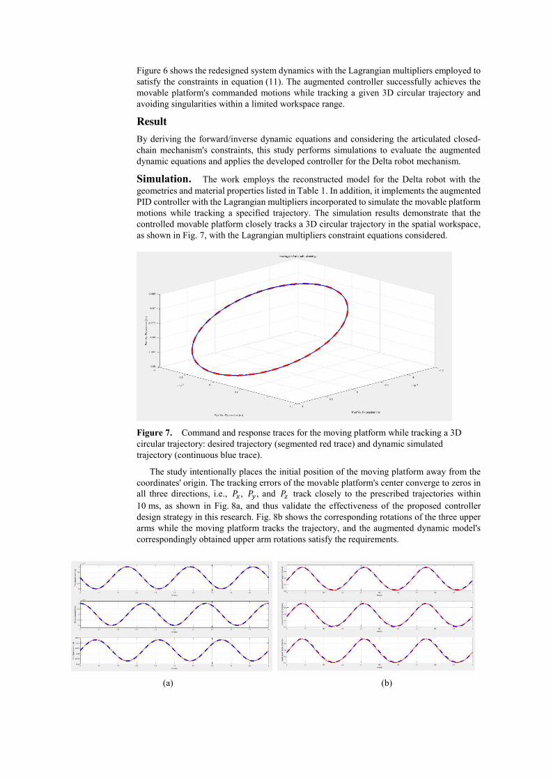
Figure 6 shows the redesigned system dynamics with the Lagrangian multipliers employed to
satisfy the constraints in equation (11). The augmented controller successfully achieves the
movable platform's commanded motions while tracking a given 3D circular trajectory and
avoiding singularities within a limited workspace range.
Result
By deriving the forward/inverse dynamic equations and considering the articulated closed-
chain mechanism's constraints, this study performs simulations to evaluate the augmented
dynamic equations and applies the developed controller for the Delta robot mechanism.
Simulation. The work employs the reconstructed model for the Delta robot with the
geometries and material properties listed in Table 1. In addition, it implements the augmented
PID controller with the Lagrangian multipliers incorporated to simulate the movable platform
motions while tracking a specified trajectory. The simulation results demonstrate that the
controlled movable platform closely tracks a 3D circular trajectory in the spatial workspace,
as shown in Fig. 7, with the Lagrangian multipliers constraint equations considered.
Figure 7. Command and response traces for the moving platform while tracking a 3D
circular trajectory: desired trajectory (segmented red trace) and dynamic simulated
trajectory (continuous blue trace).
The study intentionally places the initial position of the moving platform away from the
coordinates' origin. The tracking errors of the movable platform's center converge to zeros in
all three directions, i.e., 𝑃𝑥 , 𝑃𝑦 , and 𝑃𝑧 track closely to the prescribed trajectories within
10 ms, as shown in Fig. 8a, and thus validate the effectiveness of the proposed controller
design strategy in this research. Fig. 8b shows the corresponding rotations of the three upper
arms while the moving platform tracks the trajectory, and the augmented dynamic model's
correspondingly obtained upper arm rotations satisfy the requirements.
(a) (b)

Figure 8. Delta robot motion while tracking a 3D circular trajectory. (a) Displacements of
the moving platform, from top to bottom: 𝑃𝑥, 𝑃𝑦, and 𝑃𝑧, respectively; (b) Rotations of the
three upper arms, from top to bottom: upper arm1, upper arm2, and upper arm3, respectively.
The study also examines the moving platform's velocities in three directions. The moving
platform moves from initial zero velocity and fast converges to the requested velocity within
1 ms. The moving platform's maximum velocity is 0.02 m/s in the x-direction and y-direction
and 0.3 m/s in the z-direction, which is reasonable in the limited workspace.
Due to the promptly demanded tracking responses, there are minimal initial differences
between the desired and controlled moving platform motion traces. Nevertheless, the
developed controller achieves the 3D circular path tracking while experiencing certain
variations for the Lagrangian multipliers, which successfully adapts the augmented controller
to achieve track performance.
The simulation results verify that the developed controller can successfully command the
moving platform to track prescribed trajectories with incorporated mechanical constraints.
The developed strategy is beneficial to investigate other types of controllers for the Delta
robot for tracking purposes. Because it is intuitive and straightforward to construct the
platform using the proposed strategy, adjusting the robot's geometry and other parameters
when the design requests modifications are convenient.
Discussion
This research develops an effective tracking controller for a Delta robot based upon a strategy
using the Lagrangian equations of motion for the articulated closed-chain mechanism and
incorporating the Lagranign multipliers for the constraints. The study reformulates the
forward/inverse dynamic equations of motion and integrates the mechanism constraint
equations to acquire state equations for the Delta robot dynamics. As a result, the augmented
system now employs six states, including the moving platform's three center coordinates and
three Lagrangian multipliers, to dominate the mechanism's dynamics in resolving the
demanded motor torques and tracking positions.
The work applies a tuned PID controller for the movable platforms to track prescribed
trajectories with the developed controlling strategy and the constraints considered. During the
PID controller functions period, the developed system closely tracks the prescribed trajectory
and feedback on the movable platform's current motion for tuning and updating control
parameters. Furthermore, during all the tracking timespan, the system dynamics demand
satisfying the Lagrangian equations of the motion and constraint equations for the Lagrangian
multipliers.
The research results confirm that the Lagrangian formulation-based strategy can design
effective tracking controllers for Delta robot mechanisms. Furthermore, the Delta robot's
moving platform achieves satisfactory tracking performance using the developed controller
with Lagrangian multipliers. Hence, the proposed design approach facilitates the
reformulation of complex dynamics equations with mechanism constraints, improving
dynamic modeling efficiency and tracking controller performance.
References
1. Cuong, T. D., Tho, T. P. & Thinh, N. T. A generalized approach on design and control
methods synthesis of delta robot. Journal Research Notes in Information Science 13, 179
(2013).
2. Boudjedir, C. E., Boukhetala, D. & Bouri, M. Nonlinear PD plus sliding mode control
with application to a parallel delta robot. Journal Of Electrical Engineering-Elektrotechnicky
Casopis 69, 329-336. DOI: 10.2478/jee-2018–004 (2018).
3. Can, F. C., Hepeyiler, M. & Başer, Ö. A novel inverse kinematic approach for delta parallel robot. Int. J. Mate. Mech. Manuf. 6, 321-326. DOI: 10.18178/ijmmm.2018.6.5.400
(2018).
4. Brinker, J., Funk, N., Ingenlath, P., Takeda, Y. & Corves, B. Comparative study of
serial-parallel delta robots with full orientation capabilities. Journal IEEE Robotics
Automation Letters 2, 920-926. DOI: 10.1109/LRA.2017.2654551 (2017).

5. Liu, C., Cao, G. & Qu, Y. Motion simulation of Delta parallel robot based on
Solidworks and Simulink. 2019 IEEE 3rd Advanced Information Management,
Communicates, Electronic and Automation Control Conference (IMCEC). 1683-1686. DOI:
10.1109/IMCEC46724.2019.8984126 (2019).
6. Shen, H., Meng, Q., Li, J., Deng, J. & Wu, G. Kinematic sensitivity, parameter
identification and calibration of a non-fully symmetric parallel Delta robot. Mechanism
Machine Theory 161. https://doi.org/10.1016/j.mechmachtheory.2021.104311 (2021).
7. Su, T., Liang, X., He, G., Zhao, Q. & Zhao, L. Robust trajectory tracking of delta
parallel robot using sliding mode control. 2019 IEEE Symposium Series on Computational
Intelligence (SSCI). 508-512 (IEEE). DOI: 10.1109/SSCI44817.2019.9003125 (2019).
8. Kuo, Y.-L. & Huang, P.-Y. Experimental and simulation studies of motion control of a
Delta robot using a model-based approach. International Journal of Advanced Robotic
Systems 14. https://doi.org/10.1177/1729881417738738 (2017).
9. Shi, L., Miao, X. & Wang, H. An improved nonlinear proportional-integral-
differential controller combined with fractional operator and symbolic adaptation algorithm.
Transactions of the Institute of Measurement Control 42, 927-941. https:
//doi.org/10.1177/0142331219879332 (2020).
10. Zheng, K. Research on intelligent vibration suppression control of high-speed
lightweight Delta robot. Journal of Vibration and Control.
https://doi.org/10.1177/10775463211024888 (2021).
11. Sanngoen, W., Po-Ngaen, W., Charitkhuan, C. & Doungjitjaroen, K. Development of
parallel Delta robot System controller based on Raspberry Pi and FPGA. Applied Mechanics
and Materials.698-704. https://doi.org/10.4028/www.scientific.net/AMM.835.698 (2016).
12. Fabian, J., Monterrey, C. & Canahuire, R. Trajectory tracking control of a 3 DOF
delta robot: a PD and LQR comparison. 2016 IEEE XXIII International Congress on
Electronics, Electrical Engineering and Computing (INTERCON). 1-5 (IEEE). DOI:
10.1109/INTERCON.2016.7815581 (2016).
13. Aguilar-Mejia, O., Escorcia-Hernandez, J., Tapia-Olvera, R., Minor-Popocatl, H. &
Valderrabano-Gonzalez, A. Adaptive control of 3-DOF Delta parallel robot. 2019 IEEE
International Autumn Meeting on Power, Electronics and Computing (ROPEC). 1-6 (IEEE)
DOI: 10.1109/ROPEC48299.2019.9057075 (2019).
14. Boudjedir, C. E., Bouri, M. & Boukhetala, D. Model-free Iterative learning control with
nonrepetitive trajectories for second-order MIMO nonlinear systems-application to a Delta
robot. Journal IEEE Transactions on Industrial Electronics, 88(8), DOI:
10.1109/TIE.2020.3007091 (2020).
15. Du, J. & Lou, Y. Simplified dynamic model for real-time control of the delta parallel
robot. 2016 IEEE International Conference on Information and Automation (ICIA). 1647-
1652 (IEEE). DOI: 10.1109/ICInfA.2016.7832082 (2016).
16. Hentzelt, S. & Graichen, K. An augmented Lagrangian method in distributed dynamic
optimization based on approximate neighbor dynamics. 2013 IEEE International Conference
on Systems, Man, and Cybernetics. 571-576 (IEEE). DOI: 10.1109/SMC.2013.103 (2013).
17. Bortoff, S. A. Object-oriented modeling and control of delta robots. 2018 IEEE
Conference on Control Technology and Applications (CCTA). 251-258 (IEEE). DOI:
10.1109/CCTA.2018.8511395 (2018).
18. Ardestani, M. A. & Asgari, M. Modeling and analysis of a novel 3-dof spatial parallel
robot. 2012 19th International Conference on Mechatronics and Machine Vision in Practice
(M2VIP). 162-167 (IEEE). INSPEC Accession Number: 13400251 (2012).
19. Colombo, F. & Lentini, L. Prismatic Delta Robot: A Lagrangian Approach.
International Conference on Robotics in Alpe-Adria Danube Region. 315-324 (Springer).
https://doi.org/10.1007/978-3-030-48989-2_34 (2020).
20. Du, Z. Position and force control of cooperating robots using inverse dynamics,
University of Bath, (2014).
21. Angel, L. & Viola, J. Fractional order PID for tracking control of a parallel robotic
manipulator type delta. Journal ISA transactions 79, 172-188.
https://doi.org/10.1016/j.isatra.2018.04.010 (2018).
22. Ha, S., Ngoc, P. & Kim, H. Dynamics analysis of a Delta-type parallel robot.
Proceedings of the International Conference of the Society for Control Robot Systems, 47(1),
853-855, (2011).
23. Park, S. B., Kim, H. S., Song, C. & Kim, K. Dynamics modeling of a Delta-type parallel
robot. ISR 2013. 1-5 (IEEE). DOI: 10.1109/ISR.2013.6695721 (2013).
24. Lee, F.-S., Lin, C.-I., Chen, Z.-Y. & Yang, R.-X. J. C. E. Development of a control
architecture for a parallel three-axis robotic arm mechanism using CANopen
communication protocol. Concurrent Engineering, Sage Publications.
https://doi.org/10.1177/1063293X211001956. (2021).
25. López, M., Castillo, E., García, G. & Bashir, A. Delta robot: inverse, direct, and
intermediate Jacobians. Proceedings of the Institution of Mechanical Engineers, Part C:
Journal of Mechanical Engineering Science 220, 103-109.
https://doi.org/10.1243/095440606X78263 (2006).
Acknowledgments The authors are grateful to the Ministry of Science and Technology (MOST) in Taiwan
for partial financial support under contract No. 105-2221-E-211-007. The authors are also
grateful to the Education Department of Fujian under contract No. JAT190776 and
No. 2018H0033 for developing intelligent numerical controllers of industrial robots using
Biomedical Image Acquisition and Processing machine vision technologies.
Author contributions Fu-Shin Lee and Chen-I Lin performed material preparation, data collection, and analysis.
Fu-Shin Lee wrote the first draft of the manuscript and all authors commented on previous
versions of the manuscript. All authors read and approved the final manuscript.
Additional information Correspondence and requests for materials should be addressed to F.L.
Competing interests Fu-Shin Lee and Chen-I Lin declare no competing interests.


![Advanced Synthesis of the DELTA Parallel Robot for a ... · The DELTA robot (see figure 1) is one of the most famous translational parallel manipulators [5,6,7]. However, as most](https://static.fdocuments.in/doc/165x107/60deb7bb75750716bc06342b/advanced-synthesis-of-the-delta-parallel-robot-for-a-the-delta-robot-see-figure.jpg)