controller area networks and the protocol can for machine control ...
14
CONTROLLER AREA NETWORKS AND THE PROTOCOL CAN FOR MACHINE CONTROL SYSTEMS LARS-BERNO FREDRIKSSON KVASER AB P.O. Box 4076, S-511 04 Kinnahult, Sweden Abstract This article describes the benefit of control systems with a network architecture over traditional systems with a central processor. A suitable standard protocol, CAN, is briefly presented and its current and future use in textile machines is discussed. An important task is to find a way to make it possible to use standard network modules from different producers in a network specially designed for a specific machine. A solution to this problem is the design rules "CAN Kingdom" and the basics for this are presented. 1. INTRODUCTION Some ten years ago the technology of micro-controllers had reached a level that made it possible to design machines constructed of micro processor controlled stand alone actuators. These actuators are nodes in a serial network, a Controller Area Network, and are coordinated by a master computer. Such a machine architecture has several advantages, not only technical but also project managerial. In spite of this the development within this area has made little progress until recent time. The main reason for this has been the lack of a reliable standard protocol suitable for fast hard real-time communication. Such a protocol, designated CAN[1], was however developed for the automotive industry by Bosch and Intel and is now implemented in chips by the leading chip manufacturers. CAN is adopted by the textile industry and the first CAN based controller system for weaving machines appeared on the market in 1990. The first generation control systems have been completely proprietary ones but extensive work goes on to make it possible to build up advanced systems with nodes from different producers. This work has resulted in a set of design rules called "CAN Kingdom"[2], now in use as a tool in the development of the next generation of systems, not only within the textile industry. A current project is a 14-axis manipulator. 2. BENEFITS OF A NETWORK ARCHITECTURE The technology of designing machines according to a network architecture started some ten years ago. At that time the first micro-controllers appeared on the market which made it possible to design advanced electronics small enough to be integrated into mechanical machine parts, e.g. a servo controller could be physically integrated into a stand alone actuator. The basic idea of the network approach is to divide a machine into Functional Units, e.g actuator and sensor units. Each Functional Unit has a micro-controller of its own and the mechanics needed to perform a specific task. A complete machine or machine system
Transcript of controller area networks and the protocol can for machine control ...
CONTROLLER AREA NETWORKS AND THE PROTOCOL CAN FOR MACHINE CONTROL SYSTEMS
LARS-BERNO FREDRIKSSON
KVASER AB P.O. Box 4076, S-511 04 Kinnahult, Sweden
Abstract This article describes the benefit of control systems with a network architecture overtraditional systems with a central processor. A suitable standard protocol, CAN, is briefly presented and itscurrent and future use in textile machines is discussed. An important task is to find a way to make it possibleto use standard network modules from different producers in a network specially designed for a specificmachine. A solution to this problem is the design rules "CAN Kingdom" and the basics for this arepresented.
1. INTRODUCTION
Some ten years ago the technology of micro-controllers had reached a level that made it possible todesign machines constructed of micro processor controlled stand alone actuators. These actuators arenodes in a serial network, a Controller Area Network, and are coordinated by a master computer. Such amachine architecture has several advantages, not only technical but also project managerial. In spite ofthis the development within this area has made little progress until recent time. The main reason for thishas been the lack of a reliable standard protocol suitable for fast hard real-time communication. Such aprotocol, designated CAN[1], was however developed for the automotive industry by Bosch and Intel andis now implemented in chips by the leading chip manufacturers. CAN is adopted by the textile industryand the first CAN based controller system for weaving machines appeared on the market in 1990. Thefirst generation control systems have been completely proprietary ones but extensive work goes on tomake it possible to build up advanced systems with nodes from different producers. This work hasresulted in a set of design rules called "CAN Kingdom"[2], now in use as a tool in the development of thenext generation of systems, not only within the textile industry. A current project is a 14-axis manipulator.
2. BENEFITS OF A NETWORK ARCHITECTURE
The technology of designing machines according to a network architecture started some ten years ago.At that time the first micro-controllers appeared on the market which made it possible to design advancedelectronics small enough to be integrated into mechanical machine parts, e.g. a servo controller could bephysically integrated into a stand alone actuator. The basic idea of the network approach is to divide amachine into Functional Units, e.g actuator and sensor units. Each Functional Unit has a micro-controllerof its own and the mechanics needed to perform a specific task. A complete machine or machine system
is then constructed out of several Functional Units connected to an information network, often called aController Area Network, and a power network. Through these networks the Functional Units get allinformation and power needed to make all Functional Units work in concert in order to behave equivalentto or better than a traditionally designed machine. The network architecture has many advantages in comparison with a standard design using a centralmicroprocessor to carry out the control work:
- Fewer wires in the system make the wiring cheap and easy. In many cases thewiring can be reduced by 90% or more.
- Short connections to electrical noise sensitive analog sensors before thesignals are converted into digital noise insensitive messages.
- A flexible system. Functional Units can be added or removed in a simpleway.
- Simple maintenance. The electronics in many Functional Units can beidentical and fully interchangeable.
- Each Functional Unit can be developed and tested individually according toa specification given from the system demand.
A big advantage of quite another kind and therefore often overlooked is:
- The network architecture is very well suited for project oriented developmentwork.
When a machine is constructed as a combination of several Functional Units it becomes quite natural tomake the development of each Functional Unit an activity in the PERT chart of the development plan.The mechanical dimensions and behavior of the Unit, the incoming messages and the required outgoingmessages as well as their timing constrains for each Functional Unit are thoroughly specified. EachFunctional Unit can then independently be fully developed and tested according to the specification bya small group of engineers. This makes the work for the project manager quite easy as he can follow theprogress of each group and make sure that all groups keep pace with the plan. When all the FunctionalUnits are ready and fully tested according to their specifications there is a high degree of probability thatthe whole system will perform well when assembled. Project management and network management havemuch in common. The main topic for both is to make the right things happen at the right time by efficientuse of available resources. Controller Area Networks have been developed during the last decade but so far the idea has not beengenerally accepted and commonly realized in machine design. One big reason for this is that, until now,no suitable and commonly accepted protocol has been available. Thanks to the fact that the CAN protocolis implemented in commercially available chips this situation is now rapidly changing.
3. CAN OPENS THE WAY FOR MACHINE CONTROLLER AREA NETWORKS.
In 1988 Intel and Bosch presented a high speed serial protocol designated CAN. This was aimed for usein cars but it also turned out to be very well suited for industrial real-time machine control systems. CANhas many good features:
- It is fast. 1 Mb/s if the bus length is less than 40 meters.
- Non-destructive collision detection by bitwise arbitration.
- Any message has a specific priority on the bus.
- The messages have a predictable maximum latency time. A trigger messagewith no data and the highest priority can have a maximum latency time of54 µs on the bus if 1 Mb/s transfer rate is used.
- Messages can be sent point to point or be broad- or multi-casted.
- Remote messages supported. A Functional Unit can always be prepared toimmediately transmit the latest available data upon request from any otherunit.
- 2032 ( Standard CAN[1] ) or 536.870.912 ( Extended CAN[3] ) differentmessages are available, each containing 0 - 8 bytes of data.
- Powerful error detection and handling. If there is one corrupted message in1000 transmissions the total residual error probability amounts to 8.5 * 10-14
[4].
- Programmable transfer rate.
- Programmable output driver configuration.
- Low-cost CAN Controllers and µC:s with built-in CAN Controllers arecommercially available from Intel, Motorola, Philips, Siemens, NEC andsoon also from National.
- ISO STANDARD! ( ISO 11898 )
With CAN we have at last got the missing piece required for a new development era. The protocol isalmost perfect for high speed real-time control systems. It is possible to transmit full messages with eightbyte data at a rate of 7600 messages or 18000 trigger signals per second over the network. The CAN-Controllers take care of all error checking and if a message is corrupted for any reason it will automati-cally be re-transmitted at once.
3.1 A short presentation of the CAN protocol
CAN is a protocol for short messages. Each transmission can carry 0 - 8 bytes of data. This makes itsuitable for transmission of trigger signals and measurement values. It is a CSMA/AMP ( Carrier SenseMultiple Access / Arbitration by Message Priority ) type of protocol. Thus the protocol is messageoriented and each message has a specific priority according to which it gains access to the bus in case ofsimultaneous transmission. An ongoing transmission is never interrupted. Any node that want to transmita message waits until the bus is free and then starts to send the identifier of its message bit by bit. A zerois dominant over a one and a node has lost the arbitration when it has written a one but reads a zero on thebus. As soon as a node has lost the arbitration it stops transmitting but continues reading the bus signals.When the bus is free again the CAN Controller automatically makes a new attempt to transmit itsmessage. This procedure as well as error checking and retransmission of corrupted messages are done bythe CAN Controller chips. The arbitration procedure requires that there are a limited number of identifiers( in Extended CAN more than 500 million ) and that a specific identifier is sent only by one node. Theonly exception from this rule is when a message carries no data. The build up of a CAN message frameis shown in Fig. 1.. As the amount of data that can be sent in one transmission is limited to eight bytes the maximumlatency time of the highest priority message can be calculated. The maximum latency time of any messagecan be calculated if the nodes are restricted to the use of the same message identifier, once transmitted,until a specified time has elapsed. Every CAN Controller in a network will receive any message transmitted on the bus. Each node has tocheck whether a message is for him or not. Any CAN Controller on the market offers some filteringcapacity to reduce the processor capacity needed for this activity, some more elaborate than others. CAN was designed for event driven systems but it is not difficult to use the protocol in time drivensystems. Systems mixing both principles are also possible. The CAN Controller 72005 from NEC offerssome features for time tagging of messages and for synchronization of local clocks at each node.
4. CAN IN THE TEXTILE INDUSTRY
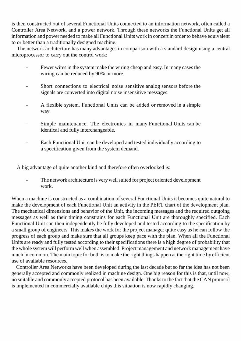
In a modern weaving mill there are three layers of data networks. On top is an ordinary ADB net forcompany management where often the Ethernet protocol is used. A second layer connects all machinesand is used for production control and this is a typical area for PROFIBUS. The third layer is the internalcommunication inside the machine and this is the right place for CAN. The textile industry has pioneeredin the use of CAN (Fig. 2.). Already in 1990 the company Dornier launched their "AT- ( Advanced Technology ) Generation" oftheir weaving machines where the control system is built up of several micro-controller modules and thesemodules communicate in real-time mode over a CAN-bus (Fig. 3.). Dornier produces two types weavingmachines; rapiers and air-jets, and some electronic units are used in both types of machines. An air-jet weaving machine is well suited to demonstrate the buildup of a textile machine around aController Area Network. In an air-jet machine the weft yarn is carried by an airstream from one side tothe other (Fig. 4.). As this stream has a short range, some 30 centimeters, the main nozzle can onlyprovide a thrust for the first part of the width. A number of relay nozzles are then needed to sustain thethrust on the inserted yarn through out the whole width of the shed. For the performance as well as for the


pro- duction cost it is essential that these relay nozzles are put to work, one group after the other, at exactly theright instants in time. If the air valves are opened to early, valuable compressed air is lost. If theyareopened too late, the yarn will not be properly stretched resulting in a weft fault in the fabric. The yarnfeeder (Fig. 5.) has to release the right amount of yarn at the right time for each pick. To do this it has a
spool-body with an adjustable diameter and an electromagnetic pin. The diameter is adjusted so that a specific number of windings will match the width of the fabric. When the shed is opened the main nozzlestretches the yarn, the feeder releases it by activating the electromagnet pin, counts released windings and,at the right number of windings, stops the yarn by closing the pin again.

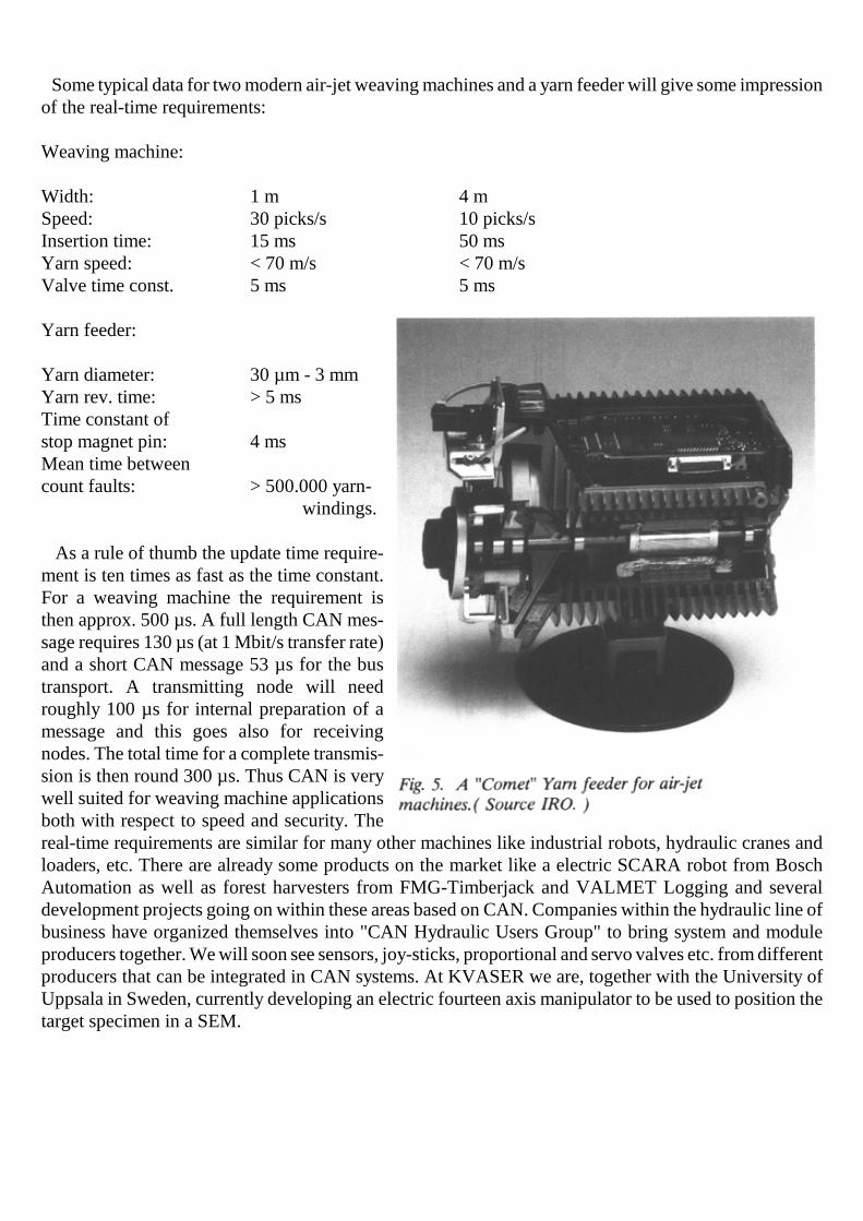
Some typical data for two modern air-jet weaving machines and a yarn feeder will give some impressionof the real-time requirements:
Weaving machine:
Width: 1 m 4 mSpeed: 30 picks/s 10 picks/sInsertion time: 15 ms 50 msYarn speed: < 70 m/s < 70 m/sValve time const. 5 ms 5 ms
Yarn feeder:
Yarn diameter: 30 µm - 3 mmYarn rev. time: > 5 msTime constant ofstop magnet pin: 4 msMean time betweencount faults: > 500.000 yarn-
windings.
As a rule of thumb the update time require-ment is ten times as fast as the time constant.For a weaving machine the requirement isthen approx. 500 µs. A full length CAN mes-sage requires 130 µs (at 1 Mbit/s transfer rate)and a short CAN message 53 µs for the bustransport. A transmitting node will needroughly 100 µs for internal preparation of amessage and this goes also for receivingnodes. The total time for a complete transmis-sion is then round 300 µs. Thus CAN is verywell suited for weaving machine applicationsboth with respect to speed and security. Thereal-time requirements are similar for many other machines like industrial robots, hydraulic cranes andloaders, etc. There are already some products on the market like a electric SCARA robot from BoschAutomation as well as forest harvesters from FMG-Timberjack and VALMET Logging and severaldevelopment projects going on within these areas based on CAN. Companies within the hydraulic line ofbusiness have organized themselves into "CAN Hydraulic Users Group" to bring system and moduleproducers together. We will soon see sensors, joy-sticks, proportional and servo valves etc. from differentproducers that can be integrated in CAN systems. At KVASER we are, together with the University ofUppsala in Sweden, currently developing an electric fourteen axis manipulator to be used to position thetarget specimen in a SEM.
4.1 Next generation weaving machine systems
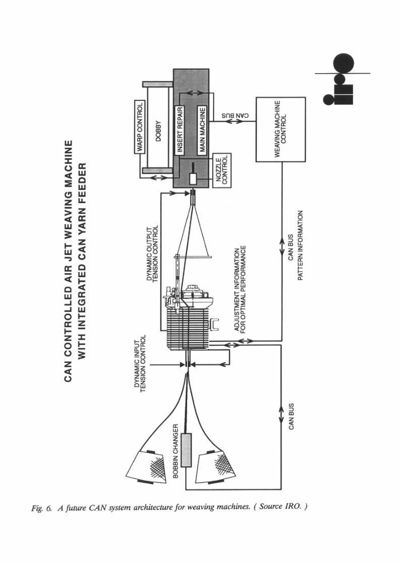
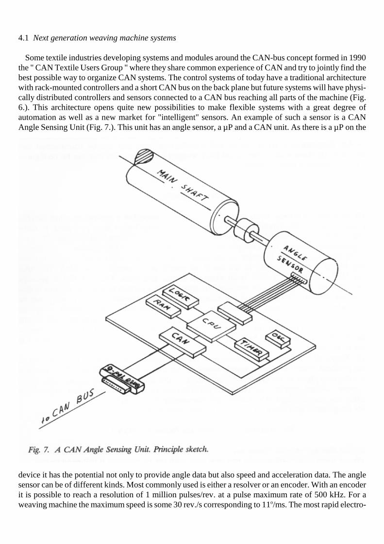
Some textile industries developing systems and modules around the CAN-bus concept formed in 1990the " CAN Textile Users Group " where they share common experience of CAN and try to jointly find thebest possible way to organize CAN systems. The control systems of today have a traditional architecturewith rack-mounted controllers and a short CAN bus on the back plane but future systems will have physi-cally distributed controllers and sensors connected to a CAN bus reaching all parts of the machine (Fig.6.). This architecture opens quite new possibilities to make flexible systems with a great degree ofautomation as well as a new market for "intelligent" sensors. An example of such a sensor is a CANAngle Sensing Unit (Fig. 7.). This unit has an angle sensor, a µP and a CAN unit. As there is a µP on the
device it has the potential not only to provide angle data but also speed and acceleration data. The anglesensor can be of different kinds. Most commonly used is either a resolver or an encoder. With an encoderit is possible to reach a resolution of 1 million pulses/rev. at a pulse maximum rate of 500 kHz. For aweaving machine the maximum speed is some 30 rev./s corresponding to 11o/ms. The most rapid electro-

mechanical devices have a time constant of 4 ms with a repeatability of some 100 µs. This gives arequired accuracy of roughly 1o and an update frequency of 10 kHz. A CAN system is able to meet thatdemand. An Angle Sensing Unit will lower the bandwidth requirement of other units in a system byproviding them not only information about actual position but also speed and acceleration. To providethis information from only one source in a system makes it more consistent and effective. Future systems will include Functional Units from several suppliers but have still to meet tough real-time demands. This has turned out to be a difficulty. The CAN protocol has many open ends that can beused to optimize system performance, e.g. the bit rate on the bus, the priority of messages, the data format,synchronization method, etc.. On the one hand the system designer would like to use these open ends tomake an optimized higher layer protocol giving his system the very best performance. On the other handa Functional Unit producer would like to produce a standard unit that fits all customers. KVASER hastogether with the members of CAN Textile Users Group spent a lot of effort to find a solution to thisproblem. The result is "CAN Kingdom". CAN Kingdom is a set of design and specification rules that canbe transformed into software tools. By these tools a Functional Unit designer can make units that can beconfigured by the system during a start-up phase.
5. CAN KINGDOM
CAN takes care of the low levels of a communication protocol but a network requires also the higherlayers. Most CAN systems running today use proprietary higher layer protocols. In many cases the systemdesigner would like to use standard units with built in node electronics. The yarn feeders described aboveis one example but you may think about robot actuators, "intelligent" electric motors, valves, etc. In orderto use such devices we will need a fully open protocol including higher layers. One way to do this is tospecify any message to be used. The SAE protocol J1939 for Bus & Trucks is an example of thisapproach. The fact that a message identifier does not only identify the message but also gives it a certainpriority on the bus makes this approach difficult. The priority of a message is set by the protocol and thispriority may be inappropriate in some systems, especially real-time control systems. The freedom ofsystem designers is very much restricted. Another disadvantage is that the defined messages will belongto a certain market, in this case the bus & trucks market. A device, e.g. an electric motor, may be suitablefor different markets and has then to be produced in several versions, differing only in the protocol to beused. CAN Kingdom[2] is a solution to overcome these problems. The software of each module containsprotocol primitives that a system designer can use to build up his own final protocol during a start-upphase of his system. An advantage of this approach is that an end-user, e.g. a robot owner, cannot corruptthe real-time performance of the robot controller network by connecting any transmitting CAN module,not foreseen by the designer. CAN Kingdom is developed on a very important basic principle, i.e:
The Modules are to Serve the Network ( MSN ).
This implies that any module connected to a network only has to announce that it is connected. Then oneor more nodes will provide this new node with the information it will need to fulfill its task in thenetwork. The usual concept of communication networks is the other way round: The Network Serves theModules ( NSM ). Then, when a module is connected to a network it already knows its role in the systemand asks for the means it will need. It is important to fully understand the difference between the MSNand NSM principles. When mechatronics is used in networks the task is often to design a machine. If thedesign is based on the MSN principle you design a network tailor-made to the needs of your machine

system. This is possible as you know all requirements a priori. If you design your machine on the NSMprinciple, the qualities of the network are given a priori and you have to design your machine accordingto the requirements of the network design. CAN Kingdom is developed specifically for machine control system use. The system is described asa country, a Kingdom, with a Capital and Cities. The King in the Capital rules the Kingdom and each Cityhas a Mayor responsible for the local government. The only way to communicate in the Kingdom is bymail. The CAN network is described as the royal Postal System and each City has a Post Office and aPostmaster, a symbol for a CAN Controller. Each City produces something. An actuator City producesmovements and measurements. Measured values can be exported to other Cities and set point values areimported from another City or Cities. The Mayor of a City has organized any export or import informationinto lists. These lists are a part of the module documentation. As a system designer has chosen specificmodules to be used in his machine he also has full knowledge about these lists, i.e. a local identifier foreach variable. By assigning CAN identifiers to these variables he can create an optimized protocol for hismachine network. To do this he designs one module, symbolized by the Capital and the King. The development of a machine with distributed actuators controlled by a network involves people ofdifferent skills, e.g. mechanics, electronics, microcomputer hardware and software, etc. It is essential thateveryone involved have a basic understanding of how the machine works and the problems of real-timeparallel computing. real-time parallel computing is a cornerstone in these machines and most often onlyone or two persons in a machine development project are familiar with this. The CAN Kingdom similevisualizes how the different modules interact and highlights the timing problem. Anyone knows that ittakes some time to write a letter and mail it, some time for the delivery, some time to read it and sometime to act upon the contents of the letter. CAN Kingdom is not only a way to specify a communicationprotocol but also a framework to specify and verify a machine and its building blocks. By the machinespecification you also have a framework for your project plan. This is a result of using the principle"Modules Serve the Network". A great advantage with the CAN Kingdom approach of not being a complete protocol but a set ofprotocol primitives is, especially for real-time systems, that the system designer can chose a, for hisapplication, suitable topology and bus access management. Although CAN is specified as a CSMA/AMPmulti-master protocol, the final protocol can be of another type, e.g. a logical slotted ring or a token busdepending on the opinion of the system designer and the provided protocol primitives available in thenodes. With the primitives in CAN Kingdom one node may be a master controlling the network bypolling the other nodes as in a traditional master-slave system like the Bitbus protocol or like the FIPprotocol. It is also possible to make a daisy chain type or token bus type protocol with the current CANKingdom version. This also includes a method to resolve queues in event driven systems in a way that cangive any message a predictable maximum latency time. The next version of CAN Kingdom will includea tool to set up a global clock and then it will be possible to create true time driven and synchronousprotocols. If CAN is used in CA ( Collision Avoiding ) type of protocol the inherent arbitration procedurewill increase the robustness of the net. Even if one module will loses its synchronization the network notgo down completely and a well designed network will be capable of a graceful degradation. Last year CAN Kingdom reached a state of practical use and a few projects started based upon it. Twoof these projects are run by KVASER customers and we take an active part in both. One is a five axis X-ray system with control loops, locally closed at each node. The other is a 14-axis manipulator workinginside an Scanning Electron Microscope. In this case the control loops are closed via the CAN network.So far the CAN Kingdom approach has met any expectations.

6. CONCLUSION
CAN can be regarded as the standard protocol for use within machines constructed of stand aloneactuators and "intelligent" sensors. CAN is fast enough for real-time performance required in such ma-chines, it has an excellent reliability and standard CAN components are cheap and designed to be used inthe harsh electrical and physical environment in a car. Its feasibility for industrial use is proven by thetextile industry where it has been used in weaving machines, installed all over the world, since 1990.Current systems are proprietary ones and there has been a great problem to find an approach that enablessystems to be constructed of stand alone units from different suppliers without loosing the real-timeperformance of CAN. This problem is now solved by the concept CAN Kingdom by which a systemdesigner can make an optimized protocol, based upon the CAN standard, for his system. This protocoldoes not have to be a multi-master CSMA/AMP protocol but can use virtually any type of accessmanagement and topology.
REFERENCES
1. ISO 11898 Road vehicles - Interchange of digital information - Controller area network (CAN) for high-speed communication.
2. L-B Fredriksson A CAN Kingdom. 921231 KVASER AB
3. CAN Specification 2.0 Part B. Robert Bosch GmbH (Automotive Group).
4. Jan Unruh, Hans-Jörg Mathony and Karl-Heinz Kaiser (Robert Bosch GmbH) Error Analysis of AutomotiveCommunication Protocols. SAE Paper 900699.