Control up to eight computer systems and their displays ... · Control up to eight computer systems...
50
KV0004A-R2 KV0004A-LED KV0004A-XTRA-LED Order toll-free in the U.S. or for FREE technical support 24/7: Call 877-877-BBOX (outside U.S. call 724-746-5500) www.blackbox.com • [email protected] Customer Support Information Freedom II Control up to eight computer systems and their displays, and share peripherals among them. Now with Glide and Switch automatic switching technology. FreedomII ZERO-TOUCHDESKTOPSWITCHING Computer K/M SPK USB2 Mode KV0008A-R2
Transcript of Control up to eight computer systems and their displays ... · Control up to eight computer systems...

KV0004A-R2 KV0004A-LED
KV0004A-XTRA-LED
Order toll-free in the U.S. or for FREE technical support 24/7: Call 877-877-BBOX (outside U.S. call 724-746-5500)www.blackbox.com • [email protected]
Customer Support
Information
Freedom II
Control up to eight computer systems and their displays, and share peripherals among them.
Now with Glide and Switch automatic switching technology.
F r e e d o m I I
Z E R O - T O U C H D E S K T O P S W I T C H I N G
Computer K/M SPK USB2 Mode
KV0008A-R2

Freedom II
877-877-2269 | blackbox.com Page 2
Trademarks Used in this Manual
Black Box and the Double Diamond logo are registered trademarks of BB Technologies, Inc.
Any other trademarks mentioned in this manual are acknowledged to be the property of the trademark owners.
We‘re here to help! If you have any questions about your application or our products, contact Black Box Tech Support at 877-877-2269
or go to blackbox.com and click on “Talk to Black Box.”You’ll be live with one of our technical experts in less than 60 seconds.

FCC and IC RFI Statements
877-877-2269 | blackbox.com Page 3
Federal Communications Commission and Industry Canada Radio Frequency Interference Statements
This equipment generates, uses, and can radiate radio-frequency energy, and if not installed and used properly, that is, in strict accordance with the manufacturer’s instructions, may cause inter ference to radio communication. It has been tested and found to comply with the limits for a Class A computing device in accordance with the specifications in Subpart B of Part 15 of FCC rules, which are designed to provide reasonable protection against such interference when the equipment is operated in a commercial environment. Operation of this equipment in a residential area is likely to cause interference, in which case the user at his own expense will be required to take whatever measures may be necessary to correct the interference.
Changes or modifications not expressly approved by the party responsible for compliance could void the user’s authority to operate the equipment.
This digital apparatus does not exceed the Class A limits for radio noise emis sion from digital apparatus set out in the Radio Interference Regulation of Industry Canada.
Le présent appareil numérique n’émet pas de bruits radioélectriques dépassant les limites applicables aux appareils numériques de la classe A prescrites dans le Règlement sur le brouillage radioélectrique publié par Industrie Canada.
Freedom II
877-877-2269 | blackbox.com Page 4
Instrucciones de Seguridad
(Normas Oficiales Mexicanas Electrical Safety Statement)
1. Todas las instrucciones de seguridad y operación deberán ser leídas antes de que el aparato eléctrico sea operado.
2. Las instrucciones de seguridad y operación deberán ser guardadas para referencia futura.
3. Todas las advertencias en el aparato eléctrico y en sus instrucciones de operación deben ser respetadas.
4. Todas las instrucciones de operación y uso deben ser seguidas.
5. El aparato eléctrico no deberá ser usado cerca del agua—por ejemplo, cerca de la tina de baño, lavabo, sótano mojado o cerca de una alberca, etc..
6. El aparato eléctrico debe ser usado únicamente con carritos o pedestales que sean recomendados por el fabricante.
7. El aparato eléctrico debe ser montado a la pared o al techo sólo como sea recomendado por el fabricante.
8. Servicio—El usuario no debe intentar dar servicio al equipo eléctrico más allá a lo descrito en las instrucciones de operación. Todo otro servicio deberá ser referido a personal de servicio calificado.
9. El aparato eléctrico debe ser situado de tal manera que su posición no interfiera su uso. La colocación del aparato eléctrico sobre una cama, sofá, alfombra o superficie similar puede bloquea la ventilación, no se debe colocar en libreros o gabinetes que impidan el flujo de aire por los orificios de ventilación.
10. El equipo eléctrico deber ser situado fuera del alcance de fuentes de calor como radiadores, registros de calor, estufas u otros aparatos (incluyendo amplificadores) que producen calor.
11. El aparato eléctrico deberá ser connectado a una fuente de poder sólo del tipo descrito en el instructivo de operación, o como se indique en el aparato.
12. Precaución debe ser tomada de tal manera que la tierra fisica y la polarización del equipo no sea eliminada.
13. Los cables de la fuente de poder deben ser guiados de tal manera que no sean pisados ni pellizcados por objetos colocados sobre o contra ellos, poniendo particular atención a los contactos y receptáculos donde salen del aparato.
14. El equipo eléctrico debe ser limpiado únicamente de acuerdo a las recomendaciones del fabricante.
15. En caso de existir, una antena externa deberá ser localizada lejos de las lineas de energia.
16. El cable de corriente deberá ser desconectado del cuando el equipo no sea usado por un largo periodo de tiempo.
17. Cuidado debe ser tomado de tal manera que objectos liquidos no sean derramados sobre la cubierta u orificios de ventilación.
18. Servicio por personal calificado deberá ser provisto cuando: A: El cable de poder o el contacto ha sido dañado; u B: Objectos han caído o líquido ha sido derramado dentro del aparato; o C: El aparato ha sido expuesto a la lluvia; o D: El aparato parece no operar normalmente o muestra un cambio en su desempeño; o E: El aparato ha sido tirado o su cubierta ha sido dañada.

Table of Contents
877-877-2269 | blackbox.com Page 5
Contents1. Specifications .............................................................................................................................................................................. 6
2. Overview .................................................................................................................................................................................... 6
2.1 Introduction ...................................................................................................................................................................... 6
2.2 Features ............................................................................................................................................................................ 8
2.3 What‘s Included ................................................................................................................................................................ 9
2.4 Additional Items You May Need ....................................................................................................................................... 9
2.5 Hardware Description ..................................................................................................................................................... 10
3. Installation ................................................................................................................................................................................ 14
3.1 Locations ......................................................................................................................................................................... 14
3.2 Mounting ....................................................................................................................................................................... 14
3.3 Connections ....................................................................................................................................................................15
3.3.1 User console ........................................................................................................................................................15
3.3.2 Computer systems ............................................................................................................................................. 16
3.3.3 Power in connections ..........................................................................................................................................17
3.3.4 Optional LED indicator connections ................................................................................................................... 19
3.3.5 Switching control via the network port .............................................................................................................. 21
3.3.6 Switching control via the Options port ............................................................................................................... 22
4. Configuration ........................................................................................................................................................................... 24
4.1 Initial configuration ......................................................................................................................................................... 24
4.1.1 Accessing the Zero Touch Switch Manager ......................................................................................................... 24
4.1.2 Logging out ........................................................................................................................................................ 24
4.1.3 Status page ........................................................................................................................................................ 25
4.1.4 General configuration ......................................................................................................................................... 26
4.1.5 Network settings ................................................................................................................................................ 27
4.1.6 User accounts ..................................................................................................................................................... 28
4.1.7 Factory reset ....................................................................................................................................................... 29
4.1.8 Upgrade ............................................................................................................................................................. 30
4.2 Glide and Switch configuration ....................................................................................................................................... 31
4.3 Multi-Monitor Glide and Switch configuration................................................................................................................ 33
4.4 Configuring LED indicators ............................................................................................................................................. 35
4.5 Additional Glide and Switch operations and settings ...................................................................................................... 37
5. Operation ................................................................................................................................................................................. 38
5.1 Selecting a computer ...................................................................................................................................................... 38
5.1.1 Selecting a computer using the Glide and Switch utility ...................................................................................... 38
5.1.2 Selecting a computer using the front panel ........................................................................................................ 39
5.1.3 Selecting a computer using hotkeys .................................................................................................................. 40
5.1.4 Selecting a computer using the mouse buttons ...................................................................................................41
Troubleshooting ........................................................................................................................................................................... 42
Appendix A. Cable pin-outs ......................................................................................................................................................... 43
Appendix B. What is True Emulation? ........................................................................................................................................... 44
Appendix C. What is Glide and Switch? ....................................................................................................................................... 46
Appendix D. Open source licences ............................................................................................................................................... 48
Appendix E. Safety information .................................................................................................................................................... 49
Lithium battery ............................................................................................................................................................ 49

Freedom II
877-877-2269 | blackbox.com Page 6
1. Specifications
Approvals: CE, FCC
Hardware Compatibility: All computers with USB interfaces
Software Compatibility: Operates with all known software and operating systems including Windows®, Linux®, Unix®, BSD, all Sun® OS, all Mac® OS, NetWare®, etc.
Connectors: Keyboard/Mouse: USB Type A female Switched USB: USB 2.0 Type A female Audio: 3.5-mm stereo jack Other: Modular 10p10c for Flash upgrade and channel switching commands
Operating Temperature: 32 to 104°F (0 to 40°C)
Power: Dual DC connectors (one power adapter included) Input: 100–240 VAC, 50/60 Hz Output: 12VDC, 1.5A Consumption: 18W
Size: KV0004A-R2: 1.22"H x 11.4"W x 5.04"D (31 x 290 x 128 mm) KV0008A-R2: 1.22"H x 17.05"W x 6.22"D (31 x 433 x 158 mm)
2. Overview
2.1 IntroductionThe Freedom II* series of switches are focused upon allowing you to seamlessly access multiple computers and their display screens, using common peripherals.
Freedom II switches allow you to use a single USB keyboard and USB mouse to fulfill functions that previously required four or eight separate sets. This provides immediate savings in both desk space and also the time required to access and control systems and screens. The KV0004A-R2 variant supports up to four connected systems while the larger KV0008A-R2 allows up to eight systems to be accessed.
Freedom II switches feature our True Emulation technology (see Appendix C), which ensures that the full characteristics of the connected USB keyboard and mouse are passed to every system.
In addition to switching the keyboard and mouse, Freedom II switches can also share a set of speakers and two separate USB peripherals between the four systems. This can be done either in concert with the keyboard and mouse (and each other) or totally independently.
Freedom II switches can be used in combination with various Black Box extender products (such as the Wizard SRX ACU5501A) to extend the distance between the user and the computers under control.
* References to Freedom II apply equally to both the KV0004A-R2 and KV0008A-R2 products.

Chapter 2: Overview
877-877-2269 | blackbox.com Page 7
Figure 2-1. Overview of the Freedom II.
Switching between the systems connected to the Freedom II can be achieved in five different ways:
• TheinnovativeGlideandSwitchautomaticswitchingutility(seeAppendixC),
• TheCOMPUTERbuttononthetoppanel,
• Keyboardhotkeycombinations,
• Mousebuttoncombinations,
• Remotecontrolbyanotherdevice.
Where additional feedback is required as to which systems and screens are selected at any time, the optional Freedom LED Monitor kit provides discreet stick-on LED monitor indicators. When a system/screen is selected, a corresponding LED monitor indicator illuminates (in a choice of colors) to confirm the action.
Glide and SwitchAn innovative in-built utility that allows the unit to automatically switch between channels by monitoring the mouse pointer position.
The keyboard/mouse, the speakers and two individual USB channels can be collectively or
separately switched through to each PC system using a variety of manual and/or automatic
switching methods.
Internalnetwork
Remoteconfigurationand control
F re e d o mI I
Z E R O - T O U C HD E S K T O P S W
I T C H I N G

Freedom II
877-877-2269 | blackbox.com Page 8
2.2 FeaturesMultiple screens, multiple systems
The Freedom II units allow you to control up to four (or up to eight) individual computer systems and their display screens using just one keyboard and mouse set. You can also share two further USB peripherals between the systems.
Multiple channel switching options
You have a choice of five different ways to switch between the various system/display channels including control by mouse but-tons, keyboard hotkeys, the unit front panel, optional remote control by another device or using our Glide and Switch technology – more on this below.
Automatic channel switching with Glide and Switch technology
Our patent pending Glide and Switch technology allows the Freedom II units to determine the precise moment that you wish to change between channels by monitoring the mouse pointer movements. All switching intelligence is fully contained within the unit, no extra software utilities are required on your mission critical computer systems.
True Emulation
Earlier USB KVM switches relied upon standard keyboard and mouse templates to tell each computer system how to deal with the connected peripherals. The Freedom II switches gather the true identities of the connected keyboard and mouse and presents those “real” profiles concurrently to every system. Thus, specialized keyboards and mice can be fully supported.
Compact size
Freedom II switches are contained within sturdy yet compact metal cases which can easily be concealed within the cable flows behind your desk.
Optional channel indicators
The Freedom LED Monitor kit provides individual indicator modules that make it easy to see which display screen is currently selected.

Chapter 2: Overview
877-877-2269 | blackbox.com Page 9
2.3 What‘s IncludedYour package should include the following items. If anything is missing or damaged, contact Black Box at 877-877-2269 or [email protected].
•FreedomIIunit
• Poweradapterandpowercord
•Flashupgradeadapter
• (4)Self-adhesivefeet
2.4 Additional Items You May Need• FreedomLEDMonitorkitwithfourstick-onindicatorsandcables(P/N:KV0004A-LED)
•USBcable(type-Atotype-B)notexceeding15feet/5m(P/N:USB05)
•3.5mmAudiocable(P/N:EJ110)

Freedom II
877-877-2269 | blackbox.com Page 10
2.5 Hardware Description
2.5.1 Top Panel (KV0004A-R2 variant)Figure 2-2 shows the top panel of the four-channel unit. Table 2-1 describes its components:
Figure 2-2. Top panel.
Table 2-1. Top panel components.
Number Component Description
1 Computer button Press to change to the next computer channel.
2 Indicators The lower four indicators (K/M, SPK, USB1, USB2) show which peripherals are switched to the current computer channel or (as you begin pressing the Mode button) the peripherals that will be switched during the next press(es) of the Computer button.
The upper four indicators scroll across at regular intervals whenever the Glide and Switch channel switching system is enabled.
The seven-segment numeric display indicates the computer channel that is currently active.
3 Mode button Press to determine which peripherals should be switched to another computer channel (will occur when you press the Computer button).
1 2 3
F r e e d o m I I
Z E R O - T O U C H D E S K T O P S W I T C H I N G
Computer K/M SPK USB2 Mode

Chapter 2: Overview
877-877-2269 | blackbox.com Page 11
2.5.2 Rear Panel (KV0004A-R2 variant)Figure 2-3 shows the rear panel of the four-channel unit. Table 2-2 describes its components:
Figure 2-3. Rear panel.
Table 2-2. Rear panel components.
Number Component Description
4 (2) Locking connectors Dual power inputs.
5 (2) USB Type A connectors Connect the console’s USB keyboard and mouse to these connectors.
6 3.5-mm RCA connector User console audio port: Connect optional speakers to this connector.
7 RJ-45port Optionsport:Thistop10p10cportisusedtoallowexternalcontrolofchannelswitching and also to update the internal firmware when necessary by connecting to a computer*.
8 (4) USB Type B connectors Connect to a USB port on each computer.
9 (4) 3.5-mm RCA connectors Connect to the speaker output socket on each computer (optional connection).
10 (2) USB Type A connectors Connect to the console's USB 2.0 peripheral devices (optional connection).
11 Micro USB port Reserved for future use.
12 RJ-45port Networkport-forremoteconfigurationorforconnectiontoaremoteswitchingsource, such as a Crestron™, AMX™ or similar controller.
*NOTE: The OPTIONS port uses a 10p10c socket, which can accommodate both 10p10c connectors as well as the much more common 8p8c connectors, which are used on Ethernet leads and patch cables. The pin-outs for both types of connectors are listed in Appendix A.
4 5 6 7 8 9 8 9 8 9 8 9 10 11 12

Freedom II
877-877-2269 | blackbox.com Page 12
2.5.3 Top Panel (KV0008A-R2 variant)Figure 2-4 shows the top panel of the eight-channel unit. Table 2-3 describes its components:
Figure 2-4. Top panel.
Table 2-3. Top panel components.
Number Component Description
1 Computer button Press to change to the next computer channel.
2 Indicators The lower four indicators (K/M, SPK, USB1, USB2) show which peripherals are switched to the current computer channel or (as you begin pressing the Mode button) the peripherals that will be switched during the next press(es) of the Computer button.
The upper four indicators scroll across at regular intervals whenever the Glide and Switch channel switching system is enabled.
The seven-segment numeric display indicates the computer channel that is currently active.
3 Mode button Press to determine which peripherals should be switched to another computer channel (will occur when you press the Computer button).
F r e e d o m I I
Z E R O - T O U C H D E S K T O P S W I T C H I N G
Computer K/M SPK USB2 Mode
1 2 3

Chapter 2: Overview
877-877-2269 | blackbox.com Page 13
2.5.4 Rear Panel (KV0008A-R2 variant)Figure 2-5 shows the rear panel of the eight-channel unit. Table 2-4 describes its components:
Figure 2-5. Rear panel.
Table 2-4. Rear panel components.
Number Component Description
4 (2) Locking connectors Dual power inputs.
5 (2) USB Type A connectors Connect the console’s USB keyboard and mouse to these connectors.
6 3.5-mm RCA connector User console audio port: Connect optional speakers to this connector.
7 RJ-45port Optionsport:Thistop10p10cportisusedtoallowexternalcontrolofchannelswitching and also to update the internal firmware when necessary by connecting to a computer*.
8 (8) USB Type B connectors Connect to a USB port on each computer.
9 (8) 3.5-mm RCA connectors Connect to the speaker output socket on each computer (optional connection).
10 (2) USB Type A connectors Connect to the console's USB 2.0 peripheral devices (optional connection).
11 Micro USB port Reserved for future use.
12 RJ-45port Networkport-forremoteconfigurationorforconnectiontoaremoteswitchingsource, such as a Crestron™, AMX™ or similar controller.
*NOTE: The OPTIONS port uses a 10p10c socket, which can accommodate both 10p10c connectors as well as the much more common 8p8c connectors, which are used on Ethernet leads and patch cables. The pin-outs for both types of connectors are listed in Appendix A.
INDOOR USE ONLY
12V 1.5A 12V 1.5A
8 47 36 25 1USERCONSOLE
OPTIONS
DO NOT CONNECT
TO NETWORK! USB 1
USB 2
USB 2.0SWITCHED
4 5 6 7 8 9 10 11 128 9
8 98 9
8 98 9
8 98 9

Freedom II
877-877-2269 | blackbox.com Page 14
3. Installation
3.1 LocationsPlease consider the following important points when planning the position of the Freedom II unit:
• SituatetheFreedomIIunitclosetothesystemstowhichitwillbeconnectedandneartoapoweroutlet.
• ThankstotheGlideandSwitchautomaticswitchingutility(and/ortheoptionalremotecontrol),theFreedomIIunitcanbesit-uated out of sight within the cabling cradle of a desk or placed adjacent to the connected systems.
• ConsulttheprecautionslistedwithintheSafetyinformationsection.
3.2 MountingBefore you begin connecting to the keyboard, mouse and source systems, it is advisable to mount the Freedom II unit in place, either:
• Inastandard19"rackmountcabinet(usingtheoptionalrackmountbrackets),or
• Onahorizontalsurfaceusingthesuppliedselfadhesivefeet,or
• Amongthecablingattherearofthedesk.

Chapter 3: Installation
877-877-2269 | blackbox.com Page 15
3.3 ConnectionsConnections do not need to be carried out in the order given within this guide; however, where possible connect the power in as a final step.
3.3.1 User consoleThe ports that make up the user console are where you attach the peripherals that will be shared between the computer systems. Ensure that power is disconnected from the unit.
To connect peripherals to the user console
1. Position your peripheral devices in the vicinity of the unit so that their cables will easily reach.
2. Keyboard and mouse: Attach the leads from your USB keyboard and mouse to the USB sockets specifically labeled with key-board and mouse symbols. The keyboard and mouse will operate in any of the USB sockets, however, True Emulation is not available on sockets labeled USB1 or USB2. See Figure 3-1.
Figure 3-1. Connecting the keyboard/mouse to the user console.
3. USB devices: Where required, attach the leads from your USB peripherals to the USB sockets labeled USB1 and USB2. See Figure 3-2.
Figure 3-2. Connecting USB peripherals to the user console.

Freedom II
877-877-2269 | blackbox.com Page 16
4. Audio: Where required, connect the lead from your speakers to the audio socket. See Figure 3-3.
Figure 3-3. Connecting speakers to the user console.
3.3.1.1 Support for optical S/PDIF audioThe Line In sockets on the computer ports and the Line Out socket on the user console are dual purpose. They can accept either 3.5mm analog jacks or mini- TOSLINK optical fiber connectors. The latter provide access to the optical S/PDIF (Sony/Philips Digital InterFace) capabilities supported by the Freedom II system, which switches PCM (Pulse Code Modulation) audio at 96KHz.
3.3.2 Computer systemsEach computer system is connected to the Freedom II unit using (up to) two cables. Freedom II switches support USB 2.0 (incl. USB 1.1) connections
To connect a computer system
1. Ensure that power is disconnected from the Freedom II unit and the system to be connected.
2. Use a USB cable (type-A to type-B) to link a USB port on the computer system to the USB port of the required channel on the rear of the unit. See Figure 3-4.
Figure 3-4. Connecting the USB and speaker leads from a computer to the Freedom II unit.
3. If required, use a stereo audio link cable (3.5-mm jacks at either end) to link the speaker port on the computer system to the audio port of the required channel on the rear of the unit. See Figure 3-4.
Chapter 3: Installation
877-877-2269 | blackbox.com Page 17
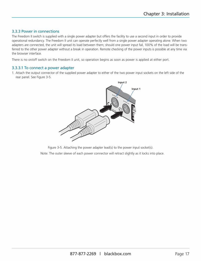
3.3.3 Power in connectionsThe Freedom II switch is supplied with a single power adapter but offers the facility to use a second input in order to provide operational redundancy. The Freedom II unit can operate perfectly well from a single power adapter operating alone. When two adapters are connected, the unit will spread its load between them; should one power input fail, 100% of the load will be trans-ferred to the other power adapter without a break in operation. Remote checking of the power inputs is possible at any time via the browser interface.
There is no on/off switch on the Freedom II unit, so operation begins as soon as power is applied at either port.
3.3.3.1 To connect a power adapter1. Attach the output connector of the supplied power adapter to either of the two power input sockets on the left side of the
rear panel. See Figure 3-5.
Figure 3-5. Attaching the power adapter lead(s) to the power input socket(s).
� Note: The outer sleeve of each power connector will retract slightly as it locks into place.
Input 1
Input 2

Freedom II
877-877-2269 | blackbox.com Page 18
Figure 3-6. Attaching the IEC connector of the power lead to the adapter.
3. Connect the power cord to a nearby main supply socket.
4. Where power redundancy is required, repeat steps 1 to 3 for a second power adapter.
IMPORTANT: Please read and adhere to the electrical safety information given within the Safety information section of this guide. In particular, do not use an unearthed power socket or extension cable.
Note: Both the switch and its power supplies generate heat when in operation and will become warm to the touch. Do not enclose them or place them in locations where air cannot circulate to cool the equipment. Do not operate the equipment in ambi-ent temperatures exceeding 40 degrees Centigrade. Do not place the products in contact with equipment whose surface temper-ature exceeds 40 degrees Centigrade.
3.3.3.2 To disconnect a power adapter1 Isolate the power adapter from the mains supply.
Note: If you are replacing one of dual power adapters during operation, it is not necessary to also remove power from the other adapter.
2 Grasp the outer body of the power adapter plug where it connects with the Freedom II unit.
3 Gently pull the body of the outer plug away from the switch. As the body of the plug slides back, it will release from the sock-et and you can fully withdraw the whole plug.
2. Connect the IEC connector of the supplied country-specific power cord to the socket of the power adapter. See Figure 3-6.

Chapter 3: Installation
877-877-2269 | blackbox.com Page 19
3.3.4 Optional LED indicator connectionsThe optional Freedom LED Monitor module (part number: KV0004A-LED) with four indicators enables you to add LED (Light Emitting Diode) indicators to each of your video display screens to show which are active.
The optional Freedom LED Monitor module connects to the OPTIONS port of the main Freedom II switch. Each individual LED monitor indicator then connects to one of the ten ports on the Freedom LED Monitor module.
Note: The Freedom LED Monitor module MUST be connected before the switch is powered on, otherwise the module will not be recognized. Also, if the module is temporarily disconnected from the switch during operation, communication between the two will cease and the switch will need to be re-powered with the Freedom LED Monitor module attached.
3.3.4.1 To connect the Freedom LED Monitor module and indicators1. Remove power from the switch. Use the flat cable supplied with the Freedom LED Monitor kit to link the module to the
OPTIONS port of the Freedom II switch. See Figure 3-7.
Link cable (Included in Freedom LED
Monitor kit)
Freedom LED Monitor module
Figure 3-7. Linking the Freedom LED Monitor module to the Freedom II switch.
Note: If a system or an external control is connected to the Options port, remove this first. It can be attached to the Freedom LED Monitor module later.
IMPORTANT: Do not connect the OPTIONS port to any network.

Freedom II
877-877-2269 | blackbox.com Page 20
2. Link each LED indicator to a port on the Freedom LED Monitor module - ports 1 to 4 are most commonly used. See Figure 3-8.
3. You need to tell the Freedom LED Monitor which LED indicator to illuminate (and in which color) for each channel. To do this connect your computer to the Freedom II switch via a network connection (see 4.1.1.1 To temporarily connect a computer to the network port) and use the Glide and Switch application. Please see the section 4.4 Configuring LED indicators.
4. Apply power to the switch.
LED indicator with 3 metre lead
Port 2
Port 3
Port 4
Insert the lead for the first indicator
into port 1
Each indicator has a self adhesive Velcro tab to assist with mounting
on your video displays.
Figure 3-8. Linking LED indicators to the Freedom LED Monitor module.
Note: The KV0004A-LED kit includes four LED indicator assemblies. Up to ten can be connected and additional LED indicators can be ordered using the part number: KV0004A-XTRA-LED.

Chapter 3: Installation
877-877-2269 | blackbox.com Page 21
3.3.5 Switching control via the network portThe network port allows switching to be controlled by commands issued from an external system such as a Crestron™ or AMX™ controller.
3.3.5.1 Connecting to a network for remote control1 Use a standard patch cable to link the network port ( ) to a network switch.
Link from network switch
3.3.5.2 Issuing remote switching commands via the network portThe Application Programming Interface (API) for the unit requires the controlling system to send an HTTP Get request to the fol-lowing location:
• <ipadress>/cgi-bin/channel
The following parameters are available:
• km=<channel> Switchesthekeyboardandmousetothedefinedchannel.
• spk=<channel> Switchesthespeakerstothedefinedchannel.
• usb1=<channel> SwitchesUSBport1tothedefinedchannel.
• usb2=<channel> SwitchesUSBport2tothedefinedchannel.
Anexamplestringis:192.168.1.22/cgi-bin/channel?km=3&spk=4&usb1=2&usb2=1
The above example would switch the keyboard and mouse to channel 3, the speakers to channel 4, USB port 1 to channel 2 and USB port 2 to channel 1.
Note: If security is enabled then the client must be authenticated before you are able to access the Freedom II.
2 Ensure that the Freedom II network port is correctly configured to a subnet that is accessible from the sending device. See Network settings for details.

Freedom II
877-877-2269 | blackbox.com Page 22
3.3.6 Switching control via the Options portThe OPTIONS port allows an external serial input, typically from a computer, to control the selection of the various channels. You can use either an optional serial cable or alternatively construct a custom cable to link the Freedom II switch and the computer. For pin-out details of the custom cable, see Appendix A.
Upon receipt of the correct code, the Freedom II will switch immediately to the appropriate channel.
3.3.6.1 Connecting a computer for remote controlThe cable link from the computer needs to connect the transmit (TXD) line of the computer to the receive (RXD) input of the Freedom II and also link the ground terminals (GND) of the two devices. See Appendix A for details.
1 Use an optional serial cable to link the OPTIONS port on the rear panel of the Freedom II switch and a vacant serial port on the computer.
� Note: If the optional Freedom LED Monitor module is used with the Freedom II, connect the computer instead to the TO KEYPAD OR PC port on the Freedom LED Monitor module.
IMPORTANT: Do not connect the OPTIONS port to any network.

Chapter 3: Installation
877-877-2269 | blackbox.com Page 23
3.3.6.2 Serial port parameter settingsEnsure that the chosen serial port is configured to the following:
• Baudrate: 1200
• Databits: 8
• Stopbit: 1
• Parity: None
3.3.6.3 Channel selection codes ASCII
Character Hex Decimal
• Channel1: ‘1’ 0x31 49
• Channel2: ‘2’ 0x32 50
• Channel3: ‘3’ 0x33 51
• Channel4: ‘4’ 0x34 52
• Channel 5: ‘5’ 0x35 53
• Channel 6: ‘6’ 0x36 54
• Channel 7: ‘7’ 0x37 55
• Channel 8: ‘8’ 0x38 56
KV0008A-R2 models only

Freedom II
877-877-2269 | blackbox.com Page 24
4. Configuration
4.1 Initial configurationThe configuration, monitoring and management of the Freedom II unit is performed using the in-built Zero Touch Switch Manager utility which is accessible via the network connection using a standard web browser.
4.1.1 Accessing the Zero Touch Switch Manager1 Use a computer that is directly or indirectly (i.e. via a network switch) connected to the Freedom II unit. If you need to make a
temporary connection, see below.
Temporary link from your computer
4.1.1.1 To temporarily connect a computer to the network port1. If you need to make a temporary connection for configuration purposes, use a standard
patch cable (cross-over or straight connections are both supported) to link the Ethernet 10/100 network port ( ) of the Freedom II unit to your computer’s network port.
Figure 4-1. The Zero Touch Switch Manager opening page
Note: If the Freedom II has been previously configured and those settings are unknown, see the Troubleshooting section for details about reverting to the default settings.
4.1.2 Logging outThere is no log out option. You merely need to close the browser that you are using to access the Zero Touch Switch Manager.
2 Run a web browser on your computer and enter the IP address of the Freedom II. The default setting is: 192.168.1.22
3 If requested, enter your username and password to log on.
Note: The default username and password are ‘admin’ and ‘password’ respectively.
The opening page of the Zero Touch Switch Manager should be displayed. See Figure 4-1.

Chapter 4: Configuration
877-877-2269 | blackbox.com Page 25
Figure 4-2. The Status page
4.1.3.2 Channel controlThe Channel control section shows the computers to which each of the user console peripheral channels are switched. You can use these entries to individually switch each peripheral to any of the four computers.
To switch peripherals between channels1. Access the Zero Touch Switch Manager.
2. If necessary, on the left side, click the Status button.
3. In the Channel control section, click the numeric field to the right of the required peripheral channel, (e.g. KM channel, speaker channel, etc.) to reveal a drop down list.
4. Click the number of the computer to which the peripheral should be switched. The Freedom II front panel display will respond when peripheral channels are switched:
• The main seven digit number shows the computer to which the KM (Keyboard and Mouse) channel is connected.
• If any of the other three channels are switched to a different channel than the KM, their respective indicators will flash.
4.1.3 Status pageThe Status page provides details about the dual power inputs, the internal operating temperature and also allows you to switch peripheral channels.
4.1.3.1 To display the Status page1. Access the Zero Touch Switch Manager.
2. The Status page is the first to be displayed, however, if necessary, click the Status button shown on the left side: The page will be displayed. See Figure 4-2.
Provides power input and internal
temperature details as well as the unit’s fixed
MAC address.
Indicates to which computer channels the various user console
peripherals are currently connected. You can click these to switch any
peripheral to another channel.
Click here to choose the
required page.

Freedom II
877-877-2269 | blackbox.com Page 26
4.1.4 General configurationThe General configuration page contains various switching and identification options.
4.1.4.1 To display the General configuration page1. Access the Zero Touch Switch Manager.
2. On the left side, click the Configuration button. See Figure 4-3.
Figure 4-3. The General configuration page4.1.4.2 Basic optionsWithin the General configuration page you can adjust various Basic options: • Hotkeys - Freedom II switches use and as their standard hotkeys. These can be changed if they clash with other
software or hardware within the installation (Ctrl + Shift, Alt + Shift, .Right Alt, etc.). • Default switching mode - Determines the standard switching mode to be used at power on (All, KM + speaker, KM only, etc.). • Mouse switching - You can enable or disable mouse switching to suit your installation requirements.• Options port mode - Determines how the serial Options port should function. Choices are Serial control to received
switching commands from a computer or RC compatible for use with an optional remote control. • Options port speed - When the setting above is set to Serial control, this setting allows you to choose the communication
speed (110 to 230400 baud). • Port cycling - Determines which computer ports should be visited when the user issues an instruction (either by mouse
buttons or keyboard hotkeys + tab) to cycle to the next port. Options are Cycle all ports (even those that are not active) or Cycle only active ports.
• Audio mixing - Allows you to route the audio channels from any (or all) computers to the user’s speakers, regardless of which computer is currently switched through to the user console. This is useful for hearing alerts that may be sounded by computers. Place a tick next to each computer whose audio you wish to route through to the user console at all times.
4.1.4.3 Keep alive optionsThis feature is used to prevent selected computers from going into sleep mode by emulating activity on the mouse/keyboard. Two modes are possible:• Onactivity-Whenchosen,keepaliveactivitiesaresentevery15secondsaslongasthelocalconsoleisinuse.Whenthelocal
console is not in use then no keep alives are sent.• Always-Whenchosen,keepaliveactivitiesaresentcontinuouslyevery15seconds.Channels: Place a tick next to each computer that needs to be kept awake.

Chapter 4: Configuration
877-877-2269 | blackbox.com Page 27
4.1.5 Network settings
4.1.5.1 To display the Network settings page1. Access the Zero Touch Switch Manager.
2. On the left side, click the Configuration button.
3. On the left side, click the Network settings option. See Figure 4-4.
Figure 4-4. The Network settings page
The various network settings are as follows:
• Require a username and password to logon - When ticked, the unit will request a valid username and password before allowing access to the Zero Touch Switch Manager.
• Obtain IP address automatically (DHCP) - When ticked, the unit will derive its IP address, netmask and gateway settings from the DHCP (Dynamic Host Configuration Protocol) server on the local network. Additionally, the optional Name entry entered within the General Configuration section can also be used when performing a DHCP search.
• Address, Netmask and Gateway - When the setting above is unticked, these three fields are used to define the fundamental network settings of the Freedom II unit. The default settings are as follows:
• Address: 192.168.1.22
• Netmask: 255.255.255.0
• Gateway: 192.168.1.1
� When the Obtain IP address... option is ticked, these three fields will display the settings that were defined by the DHCP server.
4.1.4.4 Switch identificationThis section allows you to optionally apply Name, Description and Location details to the Freedom II. For larger installations where multiple units exist, this information can be very useful for identification purposes. Additionally, the Name entry is also used when performing a DHCP search.
If the Name and Location entries are set, they will be displayed at the top of each Zero Touch Switch Manager page as the Switch ID (replacing the MAC address).

Freedom II
877-877-2269 | blackbox.com Page 28
4.1.6 User accounts
4.1.6.1 To display the User accounts page1. Access the Zero Touch Switch Manager.
2. On the left side, click the Configuration button.
3. On the left side, click the User accounts option. See Figure 4-5.
Figure 4-5. The User accounts page
4.1.6.2 Managing usersThe maximum number of declared users is limited to an administrator and up to four other users. A list of current users will be shown and you can alter the list as follows:
To edit a user1. Click on the user name.
2. Click the Edit user button.
3. Adjust the Username and/or Password as required.
� Note: The admin username cannot be changed.
4. Click the Save button.
To add a user1. Click the Add user button.
2. Enter the required Username and/or Password.
3. Click the Save button.
To delete a user1. Click on the user name.
2. Click the Edit user button.
3. Click the Delete user button.
� Note: The admin user cannot be deleted.
4. Click the Save button.

Chapter 4: Configuration
877-877-2269 | blackbox.com Page 29
4.1.7 Factory reset
4.1.7.1 To display the Factory reset page1. Access the Zero Touch Switch Manager.
2. On the left side, click the Configuration button.
3. On the left side, click the Factory reset option. See Figure 4-6.
Figure 4-6. The Factory reset page
4.1.7.2 Performing a factory resetA factory reset will return the Freedom II to its original configuration. All network settings will be reset (the default IP address of 192.168.1.22 will be restored) and all users, except for the admin user will be removed. Additionally, if any Glide and Switch lay-outs are stored, they will also be removed from memory.
There are two ways to perform a factory reset:
• Within the Factory Reset page of the Zero Touch Switch Manager, or
• Using the front panel Mode button.
Both methods are discussed below.
To perform a factory reset within Zero Touch Switch Manager1. Within the Factory Reset page, click the Factory reset button.
� The Freedom II unit will be returned to its standard state.
To perform a factory reset using the front panel MODE button1. Remove power from the Freedom II unit.
2. Press and hold the front panel MODE button and restore power.
� The Freedom II unit will be returned to its standard state.

Freedom II
877-877-2269 | blackbox.com Page 30
4.1.8 Upgrade
4.1.8.1 To display the Upgrade pageNote: Firmware upgrades are not possible using the Safari browser, please use a different browser when performing upgrades.
1. Access the Zero Touch Switch Manager.
2. On the left side, click the Upgrade button. See Figure 4-7.
Figure 4-7. The Upgrade page
4.1.8.2 Performing a firmware upgradeThe Freedom II switch is fully upgradeable via a firmware upgrade.
To perform a firmware upgrade1. Download the latest Freedom II firmware upgrade file from Black Box technical support and install it on a computer that is
attached via a network connection to the Freedom II switch.
� The file is supplied as a compressed ZIP file. Decompress the ZIP file with an appropriate tool such as WinZip (www.winzip.com) and extract the contained *.bin file.
2. Access the Upgrade page (as detailed above).
3. Click the Select upgrade file button and use the subsequent file dialog to locate the downloaded *.bin upgrade file. Once selected, the name of the upgrade file will be displayed within the Upgrade window.
4. Click the Start upgrade button. As the process begins, the Upgrade page will show ‘Upgrade in progress’ and the Freedom II front panel will show ‘ ’.
� The upgrade process may take several minutes to complete, after which time the Freedom II front panel will return to showing the current channel number.

Chapter 4: Configuration
877-877-2269 | blackbox.com Page 31
4.2 Glide and Switch configurationNote: Whenever a factory reset is performed on a Freedom II unit, the Glide and Switch Configuration will be deleted and need to be repeated.
4.2.1 Installing the Glide and Switch configuration applicationThe Glide and Switch configuration application is available for download from the Black Box website.
1. Install the application onto any computer (not necessarily one of the four computers linked to the Freedom II switch).
2. Connect the computer to the Freedom II via the network port. See To temporarily connect a computer to the network port for details.
3. Run the installation application and follow the on-screen instructions. Once installed, start the Glide and Switch application. It may report that it is ‘Unable to communicate with the device’. If so:
a. Click the OK button, whereupon the Glide and Switch window will open.
b. SelectConfigure>Connection...todisplaytheCommunicationconfigurationdialog.
c. In the first tab, select the Network connection. The Serial option is used only for the standard Freedom II switch. See Figure 4-8.
Figure 4-8. The Comms config popup
d. Enter the IP address of the Freedom II unit (it is set to 192.168.1.22 as standard) as well as the username and password, if used.
e. Ifrequired,testtheconnection.SelectConfigure>SendLayouttoSwitch.Ifnoerrormessageisreturnedthenyoucanassume the connection is working.
4.2.2 Configuring the Glide and Switch systemUse the Glide and Switch configuration application to declare the display screens and their positions relative to each other. Then download the configuration to the Freedom II unit.
1. On the icon bar, click the red, green, blue and yellow screen icons (or use the Screens menu) to add the required number of display screens to the map area. See Figure 4-9.
Figure 4-9. Adding display screens to the layout
� Note: By default, the Glide and Switch screen will automatically add four screens in a straight row ( 1A 2A 3A 4A ), each at a resolution of 1920 x 1080. You can edit or delete these screens as required.

Freedom II
877-877-2269 | blackbox.com Page 32
1A 2A 3A 4A 1A 2A3A 4A 1A
2A 3A 4A
2. Arrange the coloured rectangular screen representations to mimic the physical layout of the actual displays. See Figure 4-10.
Figure 4-10. Example screen layouts
� The important thing is to define where each screen edge abuts to the next so that the Freedom II switch can determine the correct moments to switch channels.
� Use the small black squares around the perimeter of each highlighted screen representation to change their size or stretch them.
� Note: The numbering of the screen images relate directly to the four channels on the switch.
3. Double-click on each screen representation to set the screen resolution and, optionally, add a screen name and/or configure an LED indicator (if used). See Figure 4-11.
Figure 4-11. Defining the resolution of a screen and (optionally) a name
The screen resolutions are not critical but they enable the Freedom II unit to accurately map the movement of the mouse onto corresponding movements of the pointer across the screens. The screen names, if used, are not downloaded to the Freedom II unit.
If you need to configure an LED indicator, click the LED Setup tab. Please see 4.4 Configuring LED indicators for details.
4. Whenthescreenmapiscompleteandaccuratelymatchesthetruelayoutofthedisplayscreens,chooseFile>Savetostorea copy of the layout. The layout will be stored as a ‘Glide and Switch Config file’ with the extension: .ffc
5. Tosendtheconfiguration,selectConfigure>SendLayouttoSwitch.
• If the download is successful, the screen representations will briefly turn grey and the upper four indicators on the Freedom II switch will begin to scroll across (they will continue to do this while Glide and Switch mode is enabled).
• If the download is unsuccessful, a message dialog will explain that it is ‘Unable to communicate with the device’. Check the connection and the settings mentioned in the section Installing the standard configuration application.

Chapter 4: Configuration
877-877-2269 | blackbox.com Page 33
4.3 Multi-Monitor Glide and Switch configuration
4.3.1 Installing drivers and multi-monitor config appIn order to use Multi-Monitor mode you will need to install a Multi-Monitor Glide and Switch driver (available for download from the Black Box website. Go to the Freedom II product page and click on the 'Resources' tab) onto each PC that has multiple monitors attached.
1. On each multiple monitor PC, run the downloaded file. After accepting the licence agreement you will be prompted to choose a destination folder. Either accept the suggested location or change it, as necessary.
Note: The Install for all users option should be ticked if there are more than one user account on the PC and all need to use Glide and Switch.
2. The options available during installation are as follows:
• Full Install, (this is recommended), or
• Optionstoinstallindividually:
• Configuration App. This is the Glide and Switch application and needs to be installed only on the PC that will be used to set up the Freedom II switch via the supplied flash upgrade cable and OPTIONS port.
• Visual C++ Runtime The C++ runtime library is a windows component that is required by the multi-monitor driver in order to run its helper applications. It is pre-installed with Windows but is offered here as an option as you may want to keep an older version already installed on your system, or you may already have a newer version in your copy of Windows.
• Drivers. Multi-Monitor Glide and Switch drivers that are required on each PC that will be using Multi-Monitor.
Choose the required components and click the Next > button.
3. Once the chosen components have been installed, click the Finish button.
Note: On the PC that will be used to set up the Freedom II switch, you can optionally tick ‘Click to run the Glide and Switch Configuration Application’ in the lower left corner to immediately begin using Glide and Switch - see 4.3.2 Configuring multiple monitors for details.
Note: On each PC that you installed the driver, a process called mumoapp.exe will remain running.
(Windows only)

Freedom II
877-877-2269 | blackbox.com Page 34
4.3.2 Configuring multiple monitorsMulti-Monitor configuration is similar to normal Glide and Switch setup except that you can add more than one display per PC, up to a total of eight per machine.
Note: It is necessary to install a driver on each PC that has multiple displays - see 4.3.1 Installing drivers and multi-monitor config app.
1. If it is not already running, start the Glide and Switch configuration application on the computer that is connected to the network port of the Freedom II switch. See Installing the standard configuration application for details.
2. On the icon bar, click the red, green, blue and yellow screen icons (or use the Screens menu) to add the required number of display screens per computer to the map area.
� For example, to add two monitors for PC 1, click the red computer icon twice. The two red monitor representations will be placed side by side within the Glide and Switch map area. See Figure 4-12.
� Figure 4-12. Multi-Monitor map area
3. Arrange the coloured rectangular screen representations to mimic the physical layout of the actual displays. For example, you may wish to have the two screens of PC1 side by side, with the two screen screens of PC2 below them (as shown above), or some other arrangement to reflect the actual positions of the physical monitor screens.
� The important thing is to define where each screen edge abuts to the next so that the Freedom II switch can determine the correct moments to switch channels.
� Use the small black squares around the perimeter of each highlighted screen representation to change their size or stretch them.
� Note: The numbers of the screen representations relate directly to the four channels on the Freedom II switch, while the letters relate to the screen hierarchy attached to any single computer (i.e. A is primary, B is secondary, etc.).
4. [Optional step] If you need more squares on the grid in order to arrange many displays in a row, right click on an empty square (or on the darker gray edging) to enlarge the grid. Further right clicks will add even more empty squares.
5. Continue from step 3 of the standard Glide and Switch configuration instructions.

Chapter 4: Configuration
877-877-2269 | blackbox.com Page 35
4.4 Configuring LED indicatorsWhen the optional Freedom LED Monitor indicator kit is used, there are several configuration options available that allow you to customize behavior and these are set using the Glide and Switch configuration application. See 4.2 Glide and Switch configura-tion.
4.4.1 Adjusting color and brightness for all indicatorsIf necessary, you can impose default color and brightness settings upon all connected LED monitor indicators. Choose the Configure>LEDs...menuitemtodisplaythefollowingpopup.SeeFigure4-13.
Figure 4-13. Configuring LED default color and brightness for all indicators
To impose a default color on all connected indicators, choose the required Default color and then tick the option Set all LEDs to this color.
Use the Default brightness option to determine the intensity of all indicators.
Click OK to exit and apply the required settings.
Note: Once default settings have been made you can optionally change any or all indicators individually as required using the steps outlined below.
4.4.2 Adjusting individual indicatorsFor each installed video display screen, you have the opportunity to add and configure an LED monitor indicator.
4.4.2.1 To adjust details for an individual indicator 1. Double-click on a screen representation (or right click on a screen representation and then choose Properties) to display the
screen popup.
2. Click the LED Set-up tab to display the indicator details. See Figure 4-14.
Figure 4-14. The LED Setup dialog

Freedom II
877-877-2269 | blackbox.com Page 36
Figure 4-15. Choosing an individual indicator port
4. Choose the Freedom LED Monitor output port that you wish to associate with the currently selected video screen.
5. Optionally alter the color, from the Color: list, that you wish the LED indicator to display when the associated video screen is selected. See Figure 4-16.
3. For a newly added screen the LED: entry will show No LED. Click on the drop down handle and choose the LED indicator that you wish to associate with the currently selected video display screen. See Figure 4-15.
Each entry within the LED: list relates to one of the ten output sockets on the Freedom LED Monitor module.
Note: It is possible to associate any LED indicator with more than one video screen.
Figure 4-16. Choosing a color for the chosen indicator port
6. Click OK to save and exit.
7. Repeat steps 1 to 6 for each screen that requires an LED monitor indicator.
8.ChooseConfigure>SendLayouttoSwitchtoupdatetheFreedomIIswitch.
9. IMPORTANT: Once the Glide and Switch configuration application has downloaded the setup, remove and recon-nect power to the Freedom II to allow the new settings to take effect.
Note: Each LED indicator can only have one color, so if you associate an indicator with more than one screen and then change the color on a later screen assignment, it will be changed for all the screens in the list for that LED indicator.

Chapter 4: Configuration
877-877-2269 | blackbox.com Page 37
4.5 Additional Glide and Switch operations and settingsIn addition to the core configuration functions, Glide and Switch has a number of additional settings that you can make.
4.5.1 Mouse... (acceleration) setting
4.5.2 Mouse parking... setting
Mouse accelerationMouse acceleration allows you to move the mouse pointer quickly across the large areas of the screen in response to small but sharp shifts in the mouse position. The Configure>Mouse... option provides settings between 0 and 50, however, a value of 12 to 15 will give a typical Windows-like default operation.
Mouse parking allows you to optionally determine where the mouse pointer for each system should be placed when the focus moves to a different system/video screen. The Configure>Mouse parking... option displays vertical and horizontal scroll bars. Use the scroll bars to pinpoint the position that should be used to park the dormant mouse on each screen.
4.5.3 Switch... settings
Enable (Disable) Glide and SwitchThis option allows you to switch off the Glide and Switch feature within the Freedom II unit. Located within Configure>Switch... menu item, untick the Enable Glide and Switch checkbox and download the configuration the Freedom II unit to disable.
Start-up PortLocated within Configure>Switch... menu item, this option allows you to determine which port should be enabled whenever the Freedom II unit is first powered on.
Switch ModeLocated within Configure>Switch... menu item, these check boxes allow you to determine which peripherals should be switched whenever the channel is changed by the Glide and Switch method. The switching of peripherals via the other methods of channels selection (e.g. the front panel, hotkeys, mouse buttons, etc.) remain unaffected by these settings. By default, the Keyboard/Mouse and Audio are selected.

Freedom II
877-877-2269 | blackbox.com Page 38
5. Operation
5.1 Selecting a computerThere are five ways to switch the common peripherals to specific computer channels:
• Using the innovative Glide and Switch automatic switching utility
• Using the front panel controls
• Usinghotkeys
• Usingmousebuttonpresses
• Usingexternalswitchingcontrol(RS-232orinputlines)
5.1.1 Selecting a computer using the Glide and Switch utilityOnce configured, Glide and Switch allows you to change channels merely by moving the mouse to edge of one screen towards the next screen. As the mouse pointer reaches the edge it will cause the channel to automatically change and will jump to the next screen.
Notes:
• GlideandSwitchcannotbeenableduntilalayouthasbeenconfiguredanddownloadedtotheFreedomIIunit-see4.3 Glide and Switch configuration.
• Themousewillnotflowacrossthescreenswhileanymousebuttonsarepresseddown-thispreventsundesiredbehaviorwhen dragging windows around or group-selecting items.
• YoucandeterminewhichperipheralswillbeswitchedbyGlideandSwitchindependentlyofthosethatwouldbeswitchedwith any other method. See Switch Mode within the 4.5 Additional Glide and Switch operations and settings section.
• YoucancontinuetouseanyoftheotherchannelswitchingmethodswhileGlideandSwitchisenabled.
The four upper indicators on the Freedom II display panel will scroll across every few seconds to show that Glide and Switch is enabled. See Appendix C. What is Glide and Switch? for an introduction to the utility or 4.2 Glide and Switch configuration for more details about how to prepare it for operation.
5.1.1.1 Temporarily disabling and enabling Glide and SwitchYou can temporarily disable (and re-enable) Glide and Switch using hotkey presses:
• SimultaneouslypressandholdCTRLandALT,thenpressF

Chapter 5: Operation
877-877-2269 | blackbox.com Page 39
5.1.2 Selecting a computer using the front panelThe front panel allows you to determine how the various peripherals are switched to one or more computer channels.
K/M SPK USB1 USB2MODE
MODE
MODE
MODE
MODE
Will switch all peripherals together
Will switch keyboard, mouse and speakers
Will switch only the keyboard and mouse
Will switch only the speakers
Will switch only USB peripheral 1
Will switch only USB peripheral 2
Figure 5-1. Front panel buttons and indicators.
To select a computer using the front panel
1. Optional: If you need to selectively switch some of your peripherals, press the MODE button repeatedly to change the switch-ing mode:
Figure 5-2. Changing the switching mode using the MODE button.
Note: If an indicator flashes, it signifies that the respective peripheral is currently switched to another computer channel.
The peripherals to be switched using the Glide and Switch method are set independently
2. Press the COMPUTER button repeatedly to select the required computer channel.
Use this button to choose which peripherals will be switched
The upper K/M, SPK, USB1, and USB2 indicators show which peripherals are switched to the current computer channel OR (as you begin pressing the MODE button) the peripherals that will be switched during the next press(es) of the COMPUTER button.
Use this button to choose the next required computer
Indicates the number of the currently selected computer
The lower four indicators will intermittently scroll across whenever Glide and Switch is enabled.

Freedom II
877-877-2269 | blackbox.com Page 40
5.1.3 Selecting a computer using hotkeysUsing hotkey combinations, you can quickly switch the keyboard, mouse, speakers and USB peripherals to any computer channel.
5.1.3.1 Using standard hotkey press combinationsThe standard hotkey press combinations allow you to change channels with the minimum of keypresses:
1. Simultaneously press and hold CTRL and ALT (or other hotkeys, if altered).
2. While still holding CTRL and ALT, press the number key of the required channel address (or the TAB key), then release all of the keys.
Note: The numbers on your keyboard’s numeric keypad are not valid, use only the numeral keys above the QWERTY section.
The ports (K/M, audio and/or USB) that are switched using this method depend upon the switching mode that is currently set using the front panel buttons.
The range of standard hotkey combinations are as follows:
Note: If your hotkeys have been changed, substitute them for CTRL and ALT in the examples given here.
CTRL ALT 1 Selects channel 1
CTRL ALT 2 Selects channel 2
CTRL ALT 3 Selects channel 3
CTRL ALT 4 Selects channel 4
CTRL ALT 5 Selects channel 5
CTRL ALT 6 Selects channel 6
CTRL ALT 7 Selects channel 7
CTRL ALT 8 Selects channel 8
CTRL ALT 0 Isolates the user console from all channels
CTRL ALT TAB Selects the next channel (see note below)
Choosing which computers are accessed when using hot keys + tab
The computer channels that are visited when you use the hot keys + tab (or mouse buttons) are determined by a setting within the Configuration menu:
1. Enter the Configuration menu (see Section 4.1 for details).
2. Choose the required Port cycling option, either:
• Cycle all ports (visits even inactive ports), or
• Cycle only active ports.
3. Click the Save button.
5.1.3.2 To disable/enable Glide and SwitchOnce Glide and Switch is in operation, you can temporarily disable (and re-enable) it. You can tell when Glide and Switch is in operation when the four lower indicators on the Freedom II front panel scroll across every few seconds.
• Simultaneously press and hold and , then press
KV0008A-R2 models only

Chapter 5: Operation
877-877-2269 | blackbox.com Page 41
5.1.4 Selecting a computer using the mouse buttonsUsing the mouse buttons, you can quickly switch the keyboard, mouse, speakers and/or USB peripherals to any computer chan-nel.
Note: These procedures work only with three-button or IntelliMouse devices and only if the ‘Mouse Switching’ option has been enabled.
To select a computer using the mouse buttons
1. Hold down the middle button (or scroll wheel) of the mouse.
2. Click the left mouse button to increment the channel number or click the right mouse button to decrement the channel. When the correct channel is reached, release the middle button.
When using this method of switching:
• Thecomputerchannelsthatarevisiteddependupontheconfigurationmenusetting(seenotebelow).
Choosing which computers are accessed when using mouse buttons
The computer channels that are visited when you use the hot keys + tab (or mouse buttons) are determined by a setting within the Configuration menu:
1. Enter the Configuration menu (see Section 4.1 for details).
2. Choose the required Port cycling option, either:
• Cycle all ports (visits even inactive ports), or
• Cycle only active ports.
3. Click the Save button.
• Theports(K/M,audioand/orUSB)thatareswitchedusingthismethoddependupontheswitchingmodethatiscurrentlyset using the front panel buttons.

Freedom II
877-877-2269 | blackbox.com Page 42
Troubleshooting
Problem: My computer and the Freedom II switch are connected to the same network but I can’t make contact using a web browser.
There may be another device using the same address as the Freedom II default (192.168.1.22) or your computer may be on a dif-ferent subnet.
Remedies: • Check whether any other device on your immediate network is using the same address and temporarily disconnect it, if
possible.
• Make a temporary direct connection between your computer and the switch in order to change the IP address used by the switch.
• Check that your computer and the switch are on the same subnet. If necessary, change your computer’s subnet mask setting to encompass that of the switch, e.g. instead of 255.255.255.0, try 255.255.0.0.

Appendices
877-877-2269 | blackbox.com Page 43
Serial remote control and flash upgrade cable (8p8c)
8p8c connector
D-Type female 9 way
6 2TXD RXD
3
2
3
5
RXD
GND
TXD
GND
Serial remote control and flash upgrade cable (10p10c)
10p10c connector
D-Type female 9 way
7 2TXD RXD
4
3
3
5
RXD
GND
TXD
GND
Appendix A. Cable pin-outsThe OPTIONS port uses a 10p10c socket which can accommodate both 10p10c connectors as well as the much more common 8p8c connectors, which are used on Ethernet leads and patch cables. The pin-outs are listed in this section for both types of connectors.

Freedom II
877-877-2269 | blackbox.com Page 44
Appendix B. What is True Emulation?True Emulation represents a significant breakthrough in sharing USB devices between two or more computer systems. Until this point, the problem has been how to create a USB switch that provides all of the following:
• Quick,transparentandreliableswitching,
• AccuraterepresentationoftheconnectedUSBkeyboardandmouse,
• SwitchingcontrolviatheconnectedUSBkeyboardand/ormouse.
The difficulty in achieving all of the above requirements has been due to the complexity of the USB standard. This has led to vari-ous problems that have spawned a number of possible solutions.
B.1 Enumerated USB switchingThe earliest attempts to switch USB devices applied a relatively ‘hands off’ approach. Enumerated USB switches are the electronic equivalent of those old mechanical KVM switches with a large knob on the front.
Enumerated switches are so called because a connected USB device will be required to perform a full initiation (a process called Enumeration) every time it is switched; just as if you had pulled out the plug and then reconnected it.
Enumerated switches simply pass all signals straight through between the USB device and the computer, they do not attempt to interpret any data. For most devices, this offers an advantage because the switch just leaves them to get on with their jobs with-out any interference or any hit on performance. However, it means that a USB keyboard or mouse cannot be used to control the switching process - a quick and simple control method expected by most users. Reliability of switching is also an issue that has plagued enumerated switches, especially when used with certain USB devices and particular operating systems.
B.2 Emulated USB switchingThe issues with interpreting the complex USB data streams and recreating (or Emulating) the identity of attached USB devices were eventually solved, leading to the creation of the Emulated USB switch.
A neat side effect of the technique used is that each computer can be fooled into thinking that the USB device is permanently connected to it, even when the device is switched to another computer. This means that the enumeration process for the USB device takes place only once, during the first power on. After that, a computer merely sees a dormant version of the USB device whenever the device is actually connected to a different computer.
However, it remains a complex task to dynamically assume the identity of a USB device, distribute it among the connected com-puters and maintain all of the necessary signals, states and processes. Therefore, manufacturers have previously relied upon a fixed keyboard and mouse profile that is declared to each computer, regardless of the actual connected devices. This precluded the use of any special keyboard or mouse features over and above the standard layouts.
B.3 True Emulation Mindful of the limitations associated with the previous USB switching techniques, we set about creating a more effective and ele-gant solution. After a great deal of research and development, True Emulation is the result.
True Emulation allows the complete identity of the keyboard and mouse to be copied and then presented to all of the connected computers. This means that any keyboard offering specialist function keys or any mouse with extra features will be fully supported at each computer. As with the previous emulation method, the unselected computers will continue to see the identities of the keyboard and mouse, which means that no enumeration is necessary when their link becomes active once again. This not only helps to speed up the rate of reconnection, but also raises the reliability of switching because USB links are at their most vulnera-ble during the enumeration process.
True Emulation relies upon a high speed circuit, called an Emulation Engine, to fully emulate the USB device identities and also interpret keyboard and mouse data streams. The result is full support for KVM switching control via hotkey presses or the third button/scroll wheel of a mouse.

Appendices
877-877-2269 | blackbox.com Page 45
HOSTCONTROLLER
USBKEYBOARD
OTHER USBDEVICE
USBMOUSE
USBHUB
PC1
PC2
PC3
PC4
USBHUB
USBHUB
USBHUB
EMULATIONENGINE
True Emulation is not necessarily required by other USB devices, which is why you will also find two enumerated circuits included (shown in green within the block diagram) alongside the True Emulation feature (shown in blue). This allows those other USB devices to operate at their highest speeds, without any intervention. The enumerated circuits benefit greatly from the USB Hubs that are jointly used with the True Emulation system. Because they interface directly and permanently with each computer, they help to stabilize the dormant links, making errors during enumeration much less likely.
The dual switching arrangement provides further flexibility because the True Emulation and enumerated sections can be switched in unison or independently of each other, as required. Thus, your various peripherals can operate with different computers at the same time.
Figure B-1. True Emulation functional block diagram. The emulated section of the switch is shown in blue and handles only the keyboard and mouse. The green enumerated section of the switch handles other USB devices
and also uses the USB hubs to link with the computers.

Freedom II
877-877-2269 | blackbox.com Page 46
Appendix C. What is Glide and Switch?Glide and Switch represents true innovation in KVM switching. For the first time, Glide and Switch allows users to automatically switch between target computers simply by moving the mouse pointer from screen to screen. What makes this such a revolution is that you no longer need software to be installed on your mission critical computers in order to do this. Glide and Switch resides on the switch itself, sensing screen boundaries and instantaneously switching keyboard and mouse to the defined target comput-er. Glide and Switch can be configured for almost any combination of screens using the included configuration application which allows you to declare the individual screen sizes and visually position each one relative to the others.
Figure C-1. Moving the mouse beyond a screen border causes Glide and Switch to switch the channel
Glide and Switch consists of special code within the Freedom II unit plus an intuitive graphical configuration application. First you inform the Glide and Switch configuration application how many screens you have, their pixel resolutions and how they are physi-cally arranged (e.g side-by-side, vertical stack, square formation, etc.). You then download this information to the Freedom II unit and this is used during operation to determine the precise moment to switch from one screen/system to the next.
The beauty of Glide and Switch is its simplicity of configuration and operation. Once the initial configuration has taken place, all monitoring and switching is handled within the Freedom II without need for extra connections or software utilities.

Appendices
877-877-2269 | blackbox.com Page 47
Issues when using Glide and Switch• When computers and their displays are not currently selected, the Freedom II ‘parks’ their mouse pointers in the bottom right
corner of the screen. In most cases this will cause no issues, however, it may be noticeable in circumstances such as the follow-ing:
• If the task bar is set to auto hide and it is positioned either along the bottom of the screen (as default) or along the right hand side, then the task bar will automatically reappear when the mouse pointer is parked.
• When playing full screen video, the on-screen controls (play, pause, seek etc.) will very likely be revealed when the mouse pointer is parked.
• To cure the either of the above issues, it is possible to alter the mouse parking position.
• The mouse will not flow across the screens while any mouse buttons are pressed down - this prevents undesired behaviour when dragging windows around or group-selecting items.
• Glide and Switch is not supported on Linux operating system.
• Multi-Monitor Glide and Switch is for use with the Windows operating system only and requires specialist driver to be installed on each PC. See Multi-Monitor Glide and Switch configuration for details.

Freedom II
877-877-2269 | blackbox.com Page 48
Appendix D. Open source licencesThis product includes binaries that are derived from the open source community.
======
lwIP is licenced under the BSD licence: Copyright (c) 2001-2004 Swedish Institute of Computer Science. All rights reserved.
Redistribution and use in source and binary forms, with or without modification, are permitted provided that the following condi-tions are met:
• Redistributionsofsourcecodemustretaintheabovecopyrightnotice,thislistofconditionsandthefollowingdisclaimer.
• Redistributionsinbinaryformmustreproducetheabovecopyrightnotice,thislistofconditionsandthefollowingdisclaimerinthe documentation and/or other materials provided with the distribution.
• Thenameoftheauthormaynotbeusedtoendorseorpromoteproductsderivedfromthissoftwarewithoutspecificpriorwritten permission.
THIS SOFTWARE IS PROVIDED BY THE AUTHOR “AS IS” AND ANY EXPRESS OR IMPLIED WARRANTIES, INCLUDING, BUT NOT LIMITED TO, THE IMPLIED WARRANTIES OF MERCHANTABILITY AND FITNESS FOR A PARTICULAR PURPOSE ARE DISCLAIMED. IN NO EVENT SHALL THE AUTHOR BE LIABLE FOR ANY DIRECT, INDIRECT, INCIDENTAL, SPECIAL, EXEMPLARY, OR CONSEQUENTIALDAMAGES(INCLUDING,BUTNOTLIMITEDTO,PROCUREMENTOFSUBSTITUTEGOODSORSERVICES;LOSSOF USE, DATA, OR PROFITS; OR BUSINESS INTERRUPTION) HOWEVER CAUSED AND ON ANY THEORY OF LIABILITY, WHETHER IN CONTRACT, STRICT LIABILITY, OR TORT (INCLUDING NEGLIGENCE OR OTHERWISE) ARISING IN ANY WAY OUT OF THE USE OF THIS SOFTWARE, EVEN IF ADVISED OF THE POSSIBILITY OF SUCH DAMAGE.

Appendices
877-877-2269 | blackbox.com Page 49
Appendix E. Safety information• Foruseindry,oilfreeindoorenvironmentsonly.
• Boththeunitanditspowersupplygenerateheatwheninoperationandwillbecomewarmtothetouch.Donotenclosethemor place them locations where air cannot circulate to cool the equipment. Do not operate the equipment in ambient tempera-tures exceeding 40 degrees Centigrade. Do not place the products in contact with equipment whose surface temperature exceeds 40 degrees Centigrade.
• Warning-livepartscontainedwithinpoweradapter.
• Nouserserviceablepartswithinpoweradapter-donotdismantle.
• Plug the power adapter into a socket outlet close to the module that it is powering.
• Replace a defective power adapter with a manufacturer approved type only - see the Technical Specifications on the rating label.
• Donotusethepoweradapterifthepoweradaptercaseorcablebecomesdamaged,crackedorbrokenorifyoususpectthatit is not operating properly.
• If you use a power extension cord with the unit, make sure the total ampere rating of the devices plugged into the extension cord does not exceed the cord’s ampere rating. Also, make sure that the total ampere rating of all the devices plugged into the wall outlet does not exceed the wall outlet’s ampere rating.
• Do not attempt to service the unit yourself.
Lithium batteryCAUTION: This product contains a lithium battery which must be disposed of in the correct manner.
CAUTION: RISK OF EXPLOSION IF BATTERY IS REPLACED BY AN INCORRECT TYPE.
•Ifthelithiumbatteryneedstobechanged,youmustreturntheproducttoyournearestBlackBoxdealer.Thebatterymustbereplaced by an authorized Black Box dealer.
•Oncetheproducthascometotheendofitsusefullife,thelithiumbatterymustberemovedaspartofthedecommissioningprocess and recycled in strict accordance with the regulations stipulated by your local authority. Advice on battery removal can be provided on request by Black Box.

877-877-2269 | blackbox.com
About Black BoxBlack Box provides an extensive range of networking and infrastructure products. You’ll find everything from cabinets and racks and power and surge protection products to media converters and Ethernet switches all supported by free, live 24/7 Tech support available in 60 seconds or less.
© Copyright 2017. Black Box Corporation. All rights reserved. Black Box® and the Double Diamond logo are registered trademarks of BB Technologies, Inc. Any third-party trademarks appearing in this manual are acknowledged to be the property of their respective owners.
KV0008A-R2, rev. 2.2
Black Box Tech Support: FREE! Live. 24/7.
Great tech support is just 60 seconds away at 877-877-2269 or blackbox.com.
®
NETWORK SERVICES
®
Tech support theway it should be.