Control units - REMAK · 2018-12-11 · 3 Control units VCS Design Table 2 – List of connecting...
116
INSTALLATION AND OPERATING INSTRUCTIONS 12/2014 Control units
Transcript of Control units - REMAK · 2018-12-11 · 3 Control units VCS Design Table 2 – List of connecting...

Řídicí systém pro vzduchotechnické jednotky
INS
TALL
ATIO
N A
ND
OP
ERAT
ING
INS
TRU
CTI
ON
S12
/201
4
Control units


1
Control units VCSTable of Contents
n The VCS control unit software is the intellectual property of REMAK a.s.
n VCS control units are manufactured in accordance with valid Czech and European regulations and technical stan-dards.
n VCS control units must be installed and used only in accor-dance with this documentation.
n The manufacturer is not responsible for any damage resul-ting from use for purposes other than specified in this do-cumentation, and the customer bears the risks of such use.
n The installation and operating documentation must be available for the operating and servicing staff. It is advi-sable to store this documentation close to the installed VCS control unit.
n When handling, installing, wiring, commissioning, repairing or servicing the air-handling units, it is necessary to observe valid safety rules, standards and generally recognized technical rules.
n All equipment connections must comply with the respective safety standards and regulations.
Introduction
Equipment characteristics .................................................................................................................................................................2Design .......................................................................................................................................................................................................3Documentation and Safety Measures ...........................................................................................................................................4Handling, Transport and Location ...................................................................................................................................................5Commissioning ......................................................................................................................................................................................6Control and Protection Functions ...................................................................................................................................................8Basic Operating Modes ...................................................................................................................................................................17Additional Operating Modes and Functions .............................................................................................................................17Temperature and Time Modes ......................................................................................................................................................19Control (HMI-SG controller) ............................................................................................................................................................20List of Data Points (HMI-SG controller) ......................................................................................................................................27List of Failures (HMI-SG controller) ..............................................................................................................................................43Control (HMI-DM, HMI-TM and HMI@Web controllers) ........................................................................................................46Control (HMI@Web – Installation and Connection to PC and LAN/WAN) ....................................................................48List of Data Points (HMI-DM, HMI-TM and HMI@Web controller) ...................................................................................56List of Failures (HMI-DM, HMI-TM and HMI@Web controller) ............................................................................................63Connection to the Master System (LonWorks Standard) ...................................................................................................65Connection to the Master System (ModBus Standard) .......................................................................................................71Connection to the Master System (BacNet Standard) ........................................................................................................91PLC Controller for Compressor Output Control ......................................................................................................................93Electronic Expansion Valve Overheating Controller EC3-X33 ............................................................................................98Unit Activation ................................................................................................................................................................................. 104KHD-S1_ _.R Backup System Wiring Diagram.................................................................................................................... 106Other Control, Checks and Failures ........................................................................................................................................... 107Troubleshooting .............................................................................................................................................................................. 108Spare Parts and Service ............................................................................................................................................................... 109Disposal and Recycling ................................................................................................................................................................. 109
n Any changes or modifications to individual components of the VCS control unit which could affect its safe and proper functioning are forbidden.
n Before installing and using the air-handling units, it is nece-ssary to familiarize yourself with and observe the directions and recommendations included in the following chapters.
n The VCS control units, including their individual parts, are not intended, due to their concept, for direct sale to end customers. Each installation must be performed in accordance with a professional project created by a qualified designer who is responsible for the proper selection and dimensioning of components concerning their suitability for a given application. Installation and commissioning may only be performed by an authorized company licensed in accordance with generally valid regulations.
n REMAK a.s. is not responsible for any damage, direct or indirect, caused by unauthorized or unqualified used of the software or hardware, or for any damage caused by ignoring the product's Operating Instructions.
Up-to-date version of this document is available at website www.remak.eu

2
Equipment characteristics
ApplicationVCS control units are compact control and power distribu-tors used for the decentralized regulation and control of air-handling systems. They provide the equipment with high stability and safety while allowing easy control, including the viewing of operating states. (STOP - OPERATION - AUTO).
Main FeaturesThe VCS control unit is intended for the following:
n Complex autonomous control of air-handling systems n Supply or room air temperature control (cascade control) n Supply and power actuation of air-handling systems n Protection and safeguarding of connected components
This control unit provides air-handling systems with control and safety functions. It can be equipped with the necessary number of proportional inputs and outputs depending on the required functions.Sophisticated control algorithms ensure system stabil-ity, user-friendly control and energy savings. Another advantage is that the control unit's features also contrib-ute to energy savings in air-handling system operation:
n Option to set the unit to 2 temperature modes • Comfort • Economy
n Time schedule setting options (daily or weekly time schedules)
n Additional operating mode setting options: • Optimized start • Temperature start-up • Night chilling
n Precise drive control using data communications (Modbus RTU protocol)
n Superior antifreeze protection with moderate heating of the heat exchanger during standby mode
n Precise analogue control of controlled peripheral units (according to the controlled component)
Unit DesignThese control units are designed in accordance with ČSN EN 60204-1. The unit's control and power parts are situ-ated in a single box. The components, control and actuating elements, are fitted on the DIN bars inside the control unit.Depending on the version, the VCS control unit can be provided in plastic (plastic switchboard) or in sheet-steel (sheet-steel switchboard). Both designs are equipped with transparent doors. The controls are situated below these doors. Further, the VCS control unit can be produced as a built-in assembly and a part of an air-handling unit section, which must be designed for that purpose and meet specific requirements.
Controller HW and SW ConceptThe core of the VCS system is created by a powerful Siemens Climatix series PLC controller. The control unit can be equipped with one of two POL4xx and POL6xx controller versions depending on the components used in the air-handling unit. Simultaneously, additional external input/output or commu-nication modules can be connected to the POL6xx controller.
Figure 1 – VCS control unit design
Control unit box ScrewsCircuit breakers DisconnecterMaster switch�HMI-SG controller
For local control, the HMI-SG POL822/60 hand controller can be used. The control unit allows up to 8 basic control sequences to be used depending on the air-handling unit configuration. The order of some sequences can be changed (e.g. heating-mixing damper or cooling-fan cooling).The heat pump or electric after-heater can be separated from basic sequences in the so-called extra sequences.If this is the case, another sensor must be used in the air inlet, and a special set-point must be set for this type of control. This feature can only be used after prior consultation with the manufacturer.These units are delivered adapted to individual applications so they will provide exactly those features needed for the operation of a specific air-handling device.
Power PartThe power part, like the control part, is always "tailored" for a specific air-handling unit.
Connecting terminals
Connecting terminals
Controller Siemens Climatix
�
Figure 2 – VCS control unit internal structure

3
Control units VCSDesign
Table 2 – List of connecting cables (example)Cable No.
Figure 5 – Component wiring (example)
Figure 4 – Summary of connected components (example)
BoxesVCS control units can be installed in plastic or sheet-steel boxes with transparent doors. The controls are situated below these doors. The following box dimensions are used according to the specific configuration:The degree of protection of the plastic box is IP 65 when the doors are closed and IP 40 when the doors are open The degree of protection of the sheet-steel box is IP 66 when the doors are closed and IP 20 when the doors are closed. The degree of protection of the ventilated plastic box is IP 54 when the doors are closed and IP 20 when the doors are open.The VCS control unit can also be produced as an integrated assembly and a part of the air-handling unit section. This sec-tion must be designed for that purpose and meet specific re-quirements. This section can be used to design an air-handling unit with degree of protection IP44 and outdoor air-handling units (with heated or cooled area of the control unit location).The VCS control units can be mounted on A and B combustibil-ity grade materials in accordance with EN 13501-1. Permis-sible operating temperature: 0 °C to +40 °C
Table 1 – box dimensions in mm
If needed, the boxes, sized 2000 × 800 × 400 mm and 2000 × 1000 × 400 mm, can be fitted with a ventilation set – a fan and a louver in opposite corners.
VCS
ACX36/RMK
Figure 3 – Installation in the XP unit section
DesignThe control system design is based on the selection of re-quired features and on its internal configuration. The design is performed automatically using the algorithm integrated into the design software also used for the air-handling unit design. The design output provides an exact specification of the control unit, including the following individualised lists for a specific device:
n Summary of connected components n Wiring diagrams of all components n List of all recommended cables for the connection of all
components (the cables must always be used in accord-ance with the electrical equipment project documenta-tion).
Version Height Width Depth Usual applicationPlastic 610 340 160 Vento, FP, some XP (single-speed)
Plastic 610 448 160 Vento, FP, some XP (single-speed)
Plastic 842 448 160 Vento, FP, some XP (single-speed)
Sheet-steel 800 550 250 XP, sophisticated Vento assembliesSheet-steel 1200 750 300 XPSheet-steel 1600 750 300 XPSheet-steel 2000 800 400 XPSheet-steel 2000 1000 400 XP
(Recommended) cable type Power Supply Cable length Note

4
Figure 6 – Example of access to the unit
max. 700 m
HMI-SG
Documentation
Control Unit DesignationThe control unit designation is always created by a unique code (generated by the AeroCAD design program for the control unit calculation and design), which is only included in the accompanying technical documentation (not on the control unit), and by the serial number (for communication with the manufacturer).
DocumentationVCS control systems can be installed and used only in accord-ance with the delivered documentation.
Documentation List n Product Installation and Operating Instructions n Control system configuration (summary of connected
components), terminal diagram and list of recommend-ed cables – device printout from the AeroCAD design program
Additional – General DocumentationThe system or device documentation also includes the oper-ating and inspection documentation kept during the device service life and the Service Regulations, for which the user is responsible.
Service RegulationsBefore putting the air-handling device into permanent opera-tion, the device user in collaboration with the designer, or the supplier, must issue service regulations in accordance with local regulations.We recommend including the following in these service regulations:
n Air-handling device assembly configuration, its intend-ed use and a description of its operation in all operating modes
n Description of all safety and protective elements and their functions
n Summary of the health protection principles, safety and operating rules to be observed when operating the air-handling equipment
n List of requirements for operating staff qualifications and training, nomenclature list of personnel authorized to op-erate the air-handling device
n Detailed emergency and accident instructions to be fol-lowed by the operating staff
n Operating particularities in different climatic conditions (e. g. summer or winter operation)
n Inspection, checking and maintenance schedule, includ-ing a list of checking steps, and their recording
Documentation AvailabilityThe documentation delivered with the control system (original) and operating documentation must be permanently available for the operating and service staff and stored near the air-handling equipment. The Installation and Operating Instruc-tions are also available at the website: http://www.remak.euWarningThe manufacturer reserves the right to make changes and amend the documentation due to technical innovations and changes to legislation without prior notice. Information on changes and updates are always available at the website http://www.remak.eu
Safety Measures n VCS control units are manufactured in accordance with
valid regulations and technical standards. n VCS control units must be installed and used only in ac-
cordance with this documentation. n Any damage caused by improper use contrary to this
documentation is the responsibility of the subject who failed to observe the instructions included in this docu-mentation.
n When handling, installing, wiring, commissioning, repair-ing or servicing the air-handling units, it is necessary to observe valid safety rules, standards and generally recog-nized technical rules.
n In particular, it is necessary to use suitable tools and per-sonal protective work aids (e. g. gloves) because of sharp edges and corners, respectively voltage, when perform-ing any handling, installing, dismounting, repairing or checking.
n Any changes or modifications to individual components of the VCS control unit which could affect its safe and proper functioning are forbidden.
n The air-handling equipment configuration and documen-tation must not be changed without the prior consent of the manufacturer.
n The VCS control units, including their individual parts, are not intended, due to their concept, for di-rect sale to end customers. Each installation must be performed in accordance with a professional project cre-ated by a qualified designer who is responsible for the proper selection of equipment concerning its suitability for the given application.
n All connections of the equipment, including the VCS con-trol unit, to the power mains must be performed in ac-cordance with applicable local wiring standards and reg-ulations.
n Wiring installation, commissioning, maintenance and re-pairs may only be performed by a specialized assembly company, respectively an authorized person duly quali-fied in accordance with generally valid regulations.
n Before installing and using the air-handling units, it is necessary to familiarize yourself with and observe the di-rections and recommendations included in the following chapters.
HMI-SG

5
Control units VCS
Conditions for HandlingThe device can only be commissioned, operated and serviced by qualified personnel.
n The VCS control unit can only be operated by person-nel provably trained and warned about possible dangers (by the manufacturer or authorized representative of the manufacturer) in accordance with the applicable Service Regulations for the air-handling unit.
n It is forbidden to remove, bypass or disconnect the safe-ty equipment, safety functions and guards.
n Only air-handling components in perfect condition can be used. Failures affecting the equipment safety must be re-moved immediately.
n All safety measures against electrical accidents must be strictly observed. Any action resulting in restriction, even temporary, of the safety and protection functions must be avoided.
n It is strictly forbidden to remove safety guards, casings or other safeguards, operate the equipment or its com-ponents if the safeguards are disabled or restricted.
n Any action resulting in restriction of the prescribed insu-lation of the safety voltage must be avoided.
n When changing fuses, it is necessary to ensure the non-voltage state of the control unit and use only the speci-fied fuses and protection elements.
n It is necessary to eliminate electromagnetic interference and the harmful effects of over-voltage on the signal, control and power cables, which could unintentionally ini-tiate dangerous actions and functions or cause destruc-tion of the electronic parts in individual components.
n Never work on the connected equipment under voltage! Before starting work on the air-handling unit, switch off and lock the master switch to disconnect the supply volt-age. Use protective and work aids in accordance with the Service Regulations and standards applicable in the country where the unit is installed.
n If individual technical assemblies of the air-handling unit are equipped with service switches, and if allowed by the Service Regulations, installation conditions and charac-teristics, then such assembly (e.g. heater, fan, etc.) can be disconnected by switching off and locking the corre-sponding service switch.
n Never use abrasive cleaners, cleaners unsuitable for plas-tics or acid or alkaline solutions to clean to unit.
n Avoid splashing water, impacts and vibrations. Each air-handling equipment component must always be installed in accordance with the appropriate installa-tion instructions. The manufacturer recommends fully ensuring the flaw-less condition and functioning of all protective elements and equipment. After failures, such as short circuits, have been removed, check the functionality of the automatic circuit breakers and protective elements, and verify the condition of the protective wiring interconnection and grounding.
To ensure safe operation, it is necessary to verify the con-ditions of the water heating/cooling pumps – perform manual pump turning and set the output curve (over-de-sign impairs the control quality).
Warning: If the remote control is used (including automatic schedule program), safety access must be ensured for each physical interference or entry into the air-handling unit (inspec-tion, maintenance or repair) – i. e. disconnect the power supply by turning off the switch – avoid remote initiation of the unit by other users when work is being performed on the unit.
Transport and Storage Before InstallationVCS control units are packed in cardboard boxes or installed in the corresponding air-handling unit section, if they are integrated into the air-handling unit. Measures for handling fragile goods must be taken when handling the unit.The units must be stored in rooms complying with the fol-lowing conditions:
n Maximum relative air humidity must not exceed 85 %, without water condensation
n Ambient temperature between –25 °C and +60 °CDust, water, caustics, corrosive agents or other materials negatively affecting the structure or the unit’s components (causing degradation of plastic parts and insulation) must not enter the unit.
Installation and LocationThe VCS control unit location must provide good access for the operating personnel and easy connection of the cables. The installation site must be flat without rough spots.When planning the air-handling unit location, it is necessary to keep sufficient space for maintenance, service and operating. Check the completeness and intactness of the delivery in ac-cordance with the bill of delivery before installation.These control units are designed for normal (indoor, dustless, dry, non-explosive) environments. They can be mounted on A and B combustibility grade materials in accordance with EN 13501-1.Permissible ambient temperature: +0 °C to +40 °C (24h aver-age must not exceed +35 °C)The VCS control units in the switchboard boxes are mounted in the vertical position directly on the wall. The KAEDRA plastic switchboard box can also be partially embedded under plaster. The VCS unit installed in steel switchboard boxes can also be placed directly on the floor. The cables can be run along cable trenches, cable trays or under plaster.The power cables are connected from below.We recommend the wall-mounted units be fixed to the wall using dowels and screws suitable for the wall structure.
Manipulace, transport, umístění n The air-handling equipment can only be operated in ac-
cordance with the applicable Service Regulations. The operating staff must comply with the requirements in-cluded in the Service Regulations, respectively with the manufacturer's requirements (authorisation for some service activities).
n To avoid unintentional unit start-up, the master switch must be switched off and locked when repairing the VCS unit.

6
Note: As appropriate, the above-mentioned instructions ap-ply also for control units integrated into the air-handling unit while observing the control unit installation and operating instructions delivered with the air-handling unit.
Check the completeness and intactness of the delivery in ac-cordance with the bill of delivery before installation.
Commissioning
Fitting and Wiring CheckA careful check and verification of the wiring of all control system components in accordance with the attached unit wiring diagram must be performed before the first start-up. The system cannot be connected to the power supply until these checks have been performed.First of all, it is necessary to check the presence, locations and connections of the temperature sensors, fan thermo-contacts and heaters in accordance with the M&C project. Further, the connections of all error inputs must be checked.It is also essential to check the fans, electric heaters, heat ex-changers, filters and other parts of the connected air-handling unit for correct fitting in accordance with the air-handling accompanying documentation.The above-mentioned checks must include a functionality check of each component.Special attention must be paid to the check of the conduc-tive interconnection of all parts of the air-handling unit and associated devices.
Conditions for ConnectionThe connections must be performed in accordance with the applicable local wiring standards and regulations. Before put-ting the unit into operation, an initial wiring inspection must be performed in accordance with the national regulations.
SettingsThe VCS control unit has been manufactured according to the customer’s requirements (the project), and the basic param-eters have been pre-set so that the unit is ready for operation. With these settings, the control unit will start and begin the control for the pre-set parameters providing the connection of the unit has been performed correctly.However, the professionals performing the unit commissioning must always check or adapt the air-handling unit’s operating parameters to the specific design and behaviour of the control system and operating or local conditions.It is especially necessary to pay attention to the control constants and parameter, various correction values, temperature modes and time schedules, optional modes and functions.The data points are accessible through the HMI control panel.Setting the user access levels is an important part of the settings procedure.The default factory settings must be re-set according to the user and service company needs.The Access passwords are the basic pre-set parameters which need to be reset when commissioning the unit, see the chapter Control (HMI-SG).
Additional Settings: n To optimize the interaction between the control unit and
peripheral devices, it is necessary to set, using the HMI-SG controller (see the List of Data Points in the section Settings – Control Signal Characteristic), correspond-ing values of the analogue signals for heating, cooling, heat recovery and gas heating, optional from 0–10 V and 2–10 V (pre-set). The values 2–10V are suitable for REMAK or Belimo ac-tuators.
Room temperature Measuring Point Selection n Up to two room temperature sensors can be installed in
the air-conditioned room (HMI-SG controller with an inte-grated temperature sensor plus one additional temper-ature sensor, or two HMI-SG controllers with integrated temperature sensors). The final room temperature val-ue for the control can be set as the minimum, maximum or average of both sensors (see the List of Data Points - Temperature Measuring Point Selection).
Selection of the specific point for adjusting or measuring the temperature value entering the control process results in more accurate setting of the room temperature.
WarningThe device parameters are structured and made available to users in accordance with their user roles (access levels). These roles must be assigned to the users according to their expertise and responsibility for device operation.
Basic Application Parameterization n Default and common operation parameterization is de-
scribed in the chapter Control (see particular controller).
General Overview of ParametersFor a general overview of parameters available in the menu and access authorization of users, refer to the chapter VCS – Parameter Overview and Default Factory Settings. For the menu with HMI controller parameters and default values, refer to the chapter Control (HMI-SG).
Important NotesCorrect assembly, installation, commissioning and proper control are the essential conditions for flawless and safe operation of the control unit. The components connected to the control unit must correspond with the specification in the control unit documentation. The procedures specified by the manufacturer in the unit documentation and the Service Regulations measures must be observed throughout the unit service life.
Commissioning
7
Control units VCS
Location of Control System Sensors
Inlet Air Temperature Sensor (NS 120)Control and anti–freeze sensors must always be situated behind the heater, respectively cooler – to measure the sup-ply air temperature. They must not be situated in the room.
VO antifreeze protection sensor (NS 130R) The return water temperature sensor must be situated in the return water line from the water heater so that it will be sufficiently bathed in water. The heating water circuit must ensure all the required functions for the water heater control and safety when the unit is shut down (filling the system with antifreeze mixture) as specified in the air-handling device project documentation. A capillary tube can be used as additional antifreeze protection. If it is not installed on the air-handling unit by the manufacturer, the capillary tube must be run (meandering way) through the entire cross-section of the water heater’s rear side.
Outdoor air temperature sensor (NS120)Ideally, it should be situated in the outside environment – only then are the control system’s functions ensured even in the STOP mode or immediately after unit start-up (e.g. moderate pre-heating of the exchanger based on the actual outside temperature, etc.).If the sensor is situated in the fresh air inlet duct inside the building, the measured temperature is only correct when the fans are switched on (air flows) and the starting conditions are negatively affected – which can endanger the air-handling device’s safety and even result in the water heat exchanger breaking down.
Outdoor Temperature Sensor – installed outside (NS110A)The sensor (as with any thermometer) must be installed so that objective outdoor temperature measurement will be achieved. It must be protected against negative effects like sunshine, rainfall, frost deposits, e.g. situating it under a building’s roof, using outdoor VZT roofs, situating it in the inlet louvers, inlet ducts or separate covering roof.
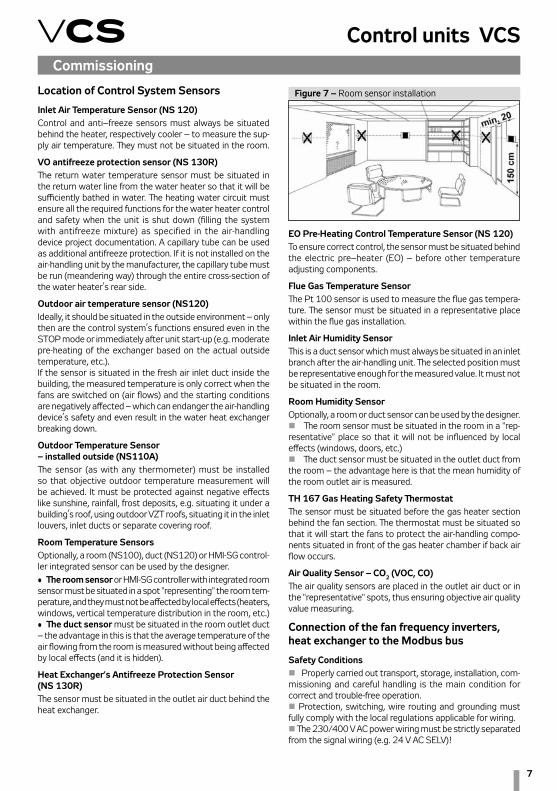
Room Temperature SensorsOptionally, a room (NS100), duct (NS120) or HMI-SG control-ler integrated sensor can be used by the designer.
Commissioning
EO Pre-Heating Control Temperature Sensor (NS 120)To ensure correct control, the sensor must be situated behind the electric pre–heater (EO) – before other temperature adjusting components.
Flue Gas Temperature SensorThe Pt 100 sensor is used to measure the flue gas tempera-ture. The sensor must be situated in a representative place within the flue gas installation.
Inlet Air Humidity SensorThis is a duct sensor which must always be situated in an inlet branch after the air-handling unit. The selected position must be representative enough for the measured value. It must not be situated in the room.
Room Humidity SensorOptionally, a room or duct sensor can be used by the designer. n The room sensor must be situated in the room in a "rep-resentative" place so that it will not be influenced by local effects (windows, doors, etc.) n The duct sensor must be situated in the outlet duct from the room – the advantage here is that the mean humidity of the room outlet air is measured.
TH 167 Gas Heating Safety ThermostatThe sensor must be situated before the gas heater section behind the fan section. The thermostat must be situated so that it will start the fans to protect the air-handling compo-nents situated in front of the gas heater chamber if back air flow occurs.
Air Quality Sensor – CO2 (VOC, CO)The air quality sensors are placed in the outlet air duct or in the "representative" spots, thus ensuring objective air quality value measuring.
Connection of the fan frequency inverters, heat exchanger to the Modbus bus
Safety Conditionsn Properly carried out transport, storage, installation, com-missioning and careful handling is the main condition for correct and trouble-free operation.n Protection, switching, wire routing and grounding must fully comply with the local regulations applicable for wiring.n The 230/400 V AC power wiring must be strictly separated from the signal wiring (e.g. 24 V AC SELV)!
Figure 7 – Room sensor installation
• The room sensor or HMI-SG controller with integrated room sensor must be situated in a spot "representing" the room tem-perature, and they must not be affected by local effects (heaters, windows, vertical temperature distribution in the room, etc.) • The duct sensor must be situated in the room outlet duct – the advantage in this is that the average temperature of the air flowing from the room is measured without being affected by local effects (and it is hidden).
Heat Exchanger's Antifreeze Protection Sensor (NS 130R)The sensor must be situated in the outlet air duct behind the heat exchanger.

8
Control and Protection Functions
Wiringn A shielded conductor must be used for the Modbus bus connection. The maximum conductor length depends on the communication speed. A maximum length of approx. 1000 m is recommended for the baud rate of 9600 Bd. The recommended conductors are included in the documentation created by the AeroCAD design program.n The controller is connected to two terminals marked A+ and B- and to the REF signal detection reference voltage terminal, which must always be interconnected with other participants on the bus.n To ensure correct functioning of the bus, the first and last device on the bus must be fitted with a terminal resistor. The first device, i.e. the master controller, terminal resistor setting is performed using the software (ensured by REMAK in the factory). The last device terminal resistor setting is performed on the last frequency inverter in the line connection. Refer to the Modbus bus wiring diagram. The setting procedure of the last terminal resistor is described in the documentation for a corresponding frequency inverter. A 120 Ohm resistor connected between the communication can also be used to terminate the wiring.
Fan Failure Detectionn To detect any fan failure, the motor thermo-contact and differential pressure sensor are connected to the frequency inverter inputs. The information provided by these elements is transmitted through the Modbus communication line to the control system, where it is processed.
Modbus RTU Communication Settingsn Each frequency inverter connected to the bus must be assigned a unique address as defined in the control system data points.
Pre-set Frequency Inverter Addresses – ModBus:
Inlet FanInlet fan address =1Backup or twin fan address =2Backup twin fan 1 address =3Backup twin fan 2 address =4
Outlet fanOutlet fan address =5Backup or twin fan address =6Backup twin fan 1 address =7Backup twin fan 2 address =8
Figure 8 – Inverter connection to the Modbus RTU
Figure 9 – Inverter association with a corresponding section
terminal resistor
Order number
Corresponding section number
RS485
FM1Master controller
FM2 FM3
WarningThe frequency inverter association cannot be exchanged between different sections! For information about frequency inverter association with a corresponding section, refer to the figure.
5
Auxiliary FanAuxiliary fan address =9Twin fan address =10
Rotary Heat RegeneratorRHR motor address =11
n The data points of all frequency inverters for communica-tion with the Modbus bus must be set in accordance with the VCS control unit: • Baud rate (9600 Bd – pre-set) • Parity (none – pre-set) • Number of stop bits (2 stop bits – pre-set) • Response time limit • Number of data bits (as standard, 8 bits – pre-set)
All data points for the used frequency inverters are available on our website: www.remak.eu
9
Control units VCS
Main Control Feature and Protection DescriptionUsing the appropriate sensors, the VCS control unit can provide comprehensive protection of the air-handling unit, such as active antifreeze protection, fan state monitoring, filter fouling or over-temperature detection of the required temperature. Any deviations from the defined states or parameters are monitored and signalled and simultaneously, safety features are activated.Depending on the failure consequence, the following happens:n The failure is only signalled and safety features are automati-cally activated. Once the failure has ceased, the unit will return to the standard mode without interference from the operator.n If a serious failure occurs, the unit will be switched to the STOP mode, and it can only be restarted after the failure has been removed and the operator's interference. The VCS control unit system enables the air-handling unit behaviour (fan action) to be set when fire is detected (external failure, inlet or outlet air high temperature).The settings can be as follows: the inlet or outlet fan is activated, both fans are activated or both fans are stopped (air-handling unit shutdown). The control unit is switched to the fire mode. The settings can be performed using the HMI controller in the List of Data Points, section Checks, System and Network Settings – Fire Alarm.
Heating ControlControl is based on the required temperature, i.e. the selected temperature mode and data from the supply air temperature sensors, outdoor temperature and the water heat exchanger return water temperature. Control can be affected by cor-rection values, maximum and minimum limits or antifreeze protection.
Water heating It is controlled by the SUMX mixing set actuator using a 0–10V continuous control signal (working range of 2–10V).
Heating Mixing Set Pump ControlThe mixing set pump is controlled depending on the outdoor temperature value and valve position (required heater output).n If the air-handling unit is in the STOP and Run mode, the pump is switched on when the outdoor temperature drops below 5°C and switched off when the outdoor temperature rises above 6°C. In this case, the pump is stopped without any run-down.n If the air-handling unit is in the Run mode, the pump is controlled by the valve actuator control algorithm. The pump is switched on when the request for the valve opening is higher than 5%.n If the pump has not been used for 168 hours, it will be switched on and turned for 60 seconds.n Failures (electrical) of the pump are sensed by the pump circuit breaker’s auxiliary contact even in the STOP mode.
Water Heater Antifreeze Protection OperationThe VCS control unit uses so-called active antifreeze protec-tion. It uses a three-stage concept.Antifreeze Protection Features:
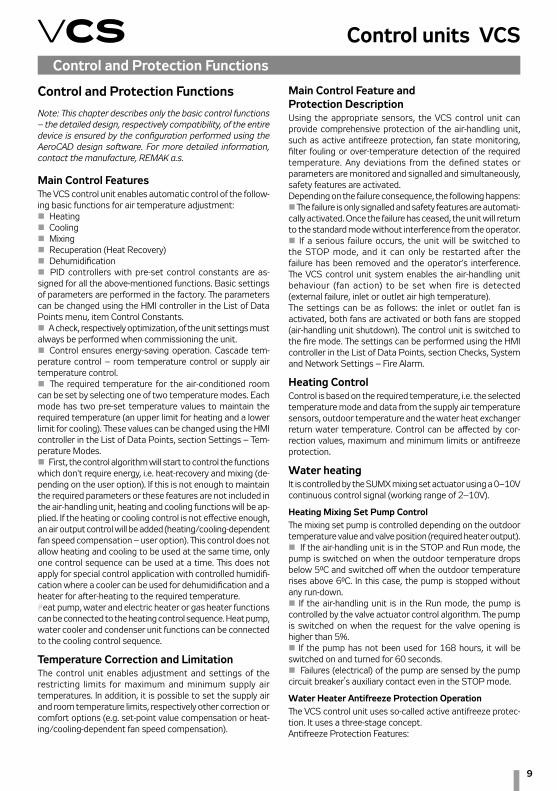
Control and Protection FunctionsNote: This chapter describes only the basic control functions – the detailed design, respectively compatibility, of the entire device is ensured by the configuration performed using the AeroCAD design software. For more detailed information, contact the manufacture, REMAK a.s.
Main Control FeaturesThe VCS control unit enables automatic control of the follow-ing basic functions for air temperature adjustment:n Heatingn Coolingn Mixingn Recuperation (Heat Recovery)n Dehumidificationn PID controllers with pre-set control constants are as-signed for all the above-mentioned functions. Basic settings of parameters are performed in the factory. The parameters can be changed using the HMI controller in the List of Data Points menu, item Control Constants.n A check, respectively optimization, of the unit settings must always be performed when commissioning the unit.n Control ensures energy-saving operation. Cascade tem-perature control – room temperature control or supply air temperature control.n The required temperature for the air-conditioned room can be set by selecting one of two temperature modes. Each mode has two pre-set temperature values to maintain the required temperature (an upper limit for heating and a lower limit for cooling). These values can be changed using the HMI controller in the List of Data Points, section Settings – Tem-perature Modes.n First, the control algorithm will start to control the functions which don't require energy, i.e. heat-recovery and mixing (de-pending on the user option). If this is not enough to maintain the required parameters or these features are not included in the air-handling unit, heating and cooling functions will be ap-plied. If the heating or cooling control is not effective enough, an air output control will be added (heating/cooling-dependent fan speed compensation – user option). This control does not allow heating and cooling to be used at the same time, only one control sequence can be used at a time. This does not apply for special control application with controlled humidifi-cation where a cooler can be used for dehumidification and a heater for after-heating to the required temperature. Heat pump, water and electric heater or gas heater functions can be connected to the heating control sequence. Heat pump, water cooler and condenser unit functions can be connected to the cooling control sequence.
Temperature Correction and LimitationThe control unit enables adjustment and settings of the restricting limits for maximum and minimum supply air temperatures. In addition, it is possible to set the supply air and room temperature limits, respectively other correction or comfort options (e.g. set-point value compensation or heat-ing/cooling-dependent fan speed compensation).
Control and Protection Functions

10
n Switching of the unit to the STOP moden Switching off of the fans n Closing of the dampersn Freezing danger signallingn Mixing set controln Pump startingn If the air-handling unit is in the Run mode, then antifreeze protection is activated when the outdoor temperature drops below 10 °C (factory settings) and the water heat exchanger return water temperature drops below 15 °C (factory set-tings). The extent of the mixing valve opening depends on the water heat exchanger’s return water temperature value. Antifreeze protection will be deactivated when temperatures rise above the limit parameters.n If the air-handling unit is in the STOP - STAND-BY mode, then antifreeze protection is activated when the outdoor temperature drops below 10 °C (factory settings) and the water heat exchanger’s return water temperature drops below 30 °C (factory settings). The extent of the mixing valve opening depends on the water heat exchanger’s return water temperature value. Antifreeze protection will be deactivated when temperatures rise above the limit parameters.n The control unit continuously monitors the water heat exchanger’s return water temperature. If the temperature is still falling and drops below 8°C (factory settings), the following protection actions will be immediately taken regardless of the outdoor temperature:n The air-handling unit will be shut down, the dampers will be closed, the fans will be switched off and the failure alarm will be activated.n The mixing valve will be opened depending on the water temperature, and the circulation pump will be switched on.n The above-mentioned state will last until the operator checks the air-handling system or removes the failure cause and confirms the air-handling system is free of failure and resets the failure.n The control unit simultaneously monitors the supply air temperature in the Run mode. If the supply air temperature drops below 6 °C (factory settings), the following protection actions will be immediately taken regardless of the outdoor temperature:n The air-handling unit will be shut down, the dampers will be closed, the fans will be switched off and the failure alarm will be activated.n The mixing valve will be opened depending on the water temperature, and the circulation pump will be switched on.
Pre-Start Unit Pre-Heating Functionsn To avoid false freezing danger assessment in winter or during transition seasons, especially when the air-handling unit is being started, the control unit features a heating circuit pre-heating.n Pre-heating is dependent on the outdoor temperature value. If the outdoor temperature is higher than 10 °C, the value of the valve opening will be 0 %, and pre-heating will not be activated. Pre-heating will be activated when the outdoor temperature drops below 10 °C. The mixing set valve will be forced to open to the value which is derived from the outdoor temperature (factory settings: +10 °C = +10 %, -10 °C = 100 %) for 120
Control and Protection Functionsseconds. Once this time has elapsed, the valve will be closed, "ramped down", until the mixing set control signal for heat-ing is reached.n If the air-handling unit is restarted within 5 minutes of the moment the air-handling unit was shut down, pre-heating will not be activated.n Antifreeze protection setting parameters can be accessed through the HMI controller in the List of Data Points menu, sections Parameters and Control Constants.
Electric HeatingElectric heating can be controlled using the following options: n Switching of the full EO, EOS heater outputn Sequential switching of the EOSX electric heater’s indi-vidual sectionsn Sequential switching of the EO heatersn Control of the EOS electric heaters using a PV valve (up to 45 kW)
Electric heater protectionn If electric heater overheating (failure) is signalled (the temperature inside the heater exceeds +80 °C) by opening the emergency thermostat contacts in the heater, this signal is interpreted by the control unit.n Electric heater control in the REMAK unit is doubled – the heater thermostat failure signal is simultaneously sent to the controller and auxiliary module.n The controller will interpret the failure signal and perform appropriate safety functions; first, the control signal for electric heating is blocked and then the heater contactor is disconnected.n The auxiliary safety module will mechanically disconnect the EO/S/X circuit breaker (i.e. it will trip the under-voltage trigger of the circuit breaker).At the same time, control logic will ensure safe cooling of the heater when the air-handling unit is being shut down – transi-tion to the STOP mode. The controller will ensure run-down of the fans (optional) so that the heating core is cooled.
Gas heating The gas heater is controlled using a burner output controller and a bypass damper (if the section is equipped with a BP damper). The required heating temperature is controlled depending on the required temperature (selected mode) and the readings from the inlet temperature, outdoor temperature and flue gas temperature sensors.
Gas Burner Output Control n Single-stage ON/OFF controln Two-stage control (two output stages)n Modular (three-point), step-less control of the entire burner output range
Burner lighting is contingent on the fan operation.At a 5 % request for heating, the 1st burner output stage is switched on. The minimum pre-set running time of this stage is 150 seconds. If the required temperature is not reached, the 2nd stage will be switched on at 70 % of the request for heating (two-stage output control). The second output stage is not restricted to the minimum running time, and will be switched off at 40 % of the request for heating.
11
Control units VCSControl and Protection Functions
Further re-lighting of the burner is possible once the protec-tion time of 150 seconds has elapsed. Modular control of the burner is step-less based on the actual requirement (set point) within the Min to Max output range of the gas burner.
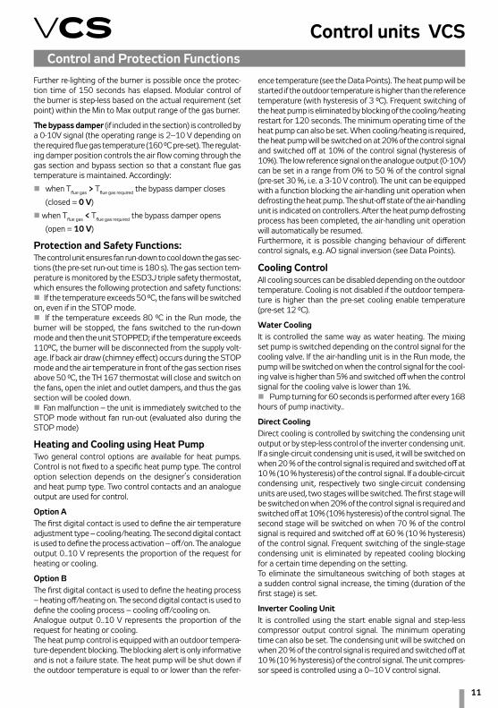
The bypass damper (if included in the section) is controlled by a 0-10V signal (the operating range is 2–10 V depending on the required flue gas temperature (160 °C pre-set). The regulat-ing damper position controls the air flow coming through the gas section and bypass section so that a constant flue gas temperature is maintained. Accordingly:
n when Tflue gas > Tflue gas required the bypass damper closes
(closed = 0 V)
n when Tflue gas < Tflue gas required the bypass damper opens
(open = 10 V)
Protection and Safety Functions:The control unit ensures fan run-down to cool down the gas sec-tions (the pre-set run-out time is 180 s). The gas section tem-perature is monitored by the ESD3J triple safety thermostat, which ensures the following protection and safety functions: n If the temperature exceeds 50 °C, the fans will be switched on, even if in the STOP mode.n If the temperature exceeds 80 °C in the Run mode, the burner will be stopped, the fans switched to the run-down mode and then the unit STOPPED; if the temperature exceeds 110°C, the burner will be disconnected from the supply volt-age. If back air draw (chimney effect) occurs during the STOP mode and the air temperature in front of the gas section rises above 50 °C, the TH 167 thermostat will close and switch on the fans, open the inlet and outlet dampers, and thus the gas section will be cooled down.n Fan malfunction – the unit is immediately switched to the STOP mode without fan run-out (evaluated also during the STOP mode)
Heating and Cooling using Heat Pump Two general control options are available for heat pumps. Control is not fixed to a specific heat pump type. The control option selection depends on the designer’s consideration and heat pump type. Two control contacts and an analogue output are used for control.
Option AThe first digital contact is used to define the air temperature adjustment type – cooling/heating. The second digital contact is used to define the process activation – off/on. The analogue output 0..10 V represents the proportion of the request for heating or cooling.
Option BThe first digital contact is used to define the heating process – heating off/heating on. The second digital contact is used to define the cooling process – cooling off/cooling on.Analogue output 0..10 V represents the proportion of the request for heating or cooling.The heat pump control is equipped with an outdoor tempera-ture-dependent blocking. The blocking alert is only informative and is not a failure state. The heat pump will be shut down if the outdoor temperature is equal to or lower than the refer-
Cooling ControlAll cooling sources can be disabled depending on the outdoor temperature. Cooling is not disabled if the outdoor tempera-ture is higher than the pre-set cooling enable temperature (pre-set 12 °C).
Water CoolingIt is controlled the same way as water heating. The mixing set pump is switched depending on the control signal for the cooling valve. If the air-handling unit is in the Run mode, the pump will be switched on when the control signal for the cool-ing valve is higher than 5% and switched off when the control signal for the cooling valve is lower than 1%. n Pump turning for 60 seconds is performed after every 168 hours of pump inactivity..
Direct CoolingDirect cooling is controlled by switching the condensing unit output or by step-less control of the inverter condensing unit. If a single-circuit condensing unit is used, it will be switched on when 20 % of the control signal is required and switched off at 10 % (10 % hysteresis) of the control signal. If a double-circuit condensing unit, respectively two single-circuit condensing units are used, two stages will be switched. The first stage will be switched on when 20% of the control signal is required and switched off at 10% (10% hysteresis) of the control signal. The second stage will be switched on when 70 % of the control signal is required and switched off at 60 % (10 % hysteresis) of the control signal. Frequent switching of the single-stage condensing unit is eliminated by repeated cooling blocking for a certain time depending on the setting.To eliminate the simultaneous switching of both stages at a sudden control signal increase, the timing (duration of the first stage) is set.
Inverter Cooling UnitIt is controlled using the start enable signal and step-less compressor output control signal. The minimum operating time can also be set. The condensing unit will be switched on when 20 % of the control signal is required and switched off at 10 % (10 % hysteresis) of the control signal. The unit compres-sor speed is controlled using a 0–10 V control signal.
ence temperature (see the Data Points). The heat pump will be started if the outdoor temperature is higher than the reference temperature (with hysteresis of 3 °C). Frequent switching of the heat pump is eliminated by blocking of the cooling/heating restart for 120 seconds. The minimum operating time of the heat pump can also be set. When cooling/heating is required, the heat pump will be switched on at 20% of the control signal and switched off at 10% of the control signal (hysteresis of 10%). The low reference signal on the analogue output (0-10V) can be set in a range from 0% to 50 % of the control signal (pre-set 30 %, i.e. a 3-10 V control). The unit can be equipped with a function blocking the air-handling unit operation when defrosting the heat pump. The shut-off state of the air-handling unit is indicated on controllers. After the heat pump defrosting process has been completed, the air-handling unit operation will automatically be resumed. Furthermore, it is possible changing behaviour of different control signals, e.g. AO signal inversion (see Data Points).

12
Control and Protection FunctionsInverter Unit and Single-Stage Condensing Unit CombinationWhen cooling is required, the inverter will be switched on first and then the output will be raised to the maximum. Consequently, the single-stage condensing unit is switched on while the inverter output is lowered to 30 % of the control signal. If the request for cooling is still rising, the inverter output will be increased from 30 % up to the maximum level of the control signal.If the request for cooling is decreasing, the inverter output will start to decrease and will be switched off at 0% of the control signal. The single-stage condensing unit is still in operation. In this phase of control, time blocking of the inverter is ap-plied and simultaneously the single-stage condensing unit is prevented from being switched off. If the request for cooling is still decreasing once this time has elapsed, the inverter will be switched on with a maximum control signal and the single-stage condensing unit will be switched off. When the single-stage condensing unit is switched off, the inverter output will be at the maximum. Then the inverter output is reduced in accordance with the request. Thus step-less control is ensured in the entire cooling capacity range.
Direct Evaporator ProtectionThis protection is ensured using the CAP 2M capillary thermo-stat, which disconnects the control signal in the event of ice build-up on the evaporator. If two evaporators are used, each of them will have its own thermostat.
Heat Recovery ControlHeat Recovery control of the rotary heat regenerator is en-sured by step-less control using the heat exchanger frequency inverter through the Modbus communication bus. The plate heat exchanger, respectively plate heat exchanger bypass, is controlled using a 0–10 V (2–10 V) continuous signal. 100% of the step-less control signal equals 100 % heat recovery, i.e. maximum speed of the rotary heat regenerator or closed bypass of the plate heat exchanger. A digital output for two-point control (ON/OFF) is another option – thus, for example, the glycol circuit pump can be switched.
Heat Exchanger Antifreeze Protectionn Rotary heat regenerator protection is ensured using the NS 120 temperature sensor situated in the outlet air duct behind the heat exchanger. If the temperature drops below the pre-set ice build-up threshold, the speed of the rotary heat regenerator will be reduced. If the speed reduction is not enough to de-freeze the heat exchanger, the heat exchanger will be stopped. The heat exchanger speed reduction depends on the PID controller’s constant setting.n Similarly as the rotary heat regenerator, control of the plate heat exchanger is ensured using the NS 120 temperature sensor and bypass actuator control. If the temperature behind the plate heat exchanger drops below the pre-set ice build-up threshold, the bypass damper actuator will be activated and the damper will stay open until the ice build-up melts from the heat exchanger. A pressure loss sensor or a CAP 3M capillary probe can also be used in some cases.Protection of the plate heat exchangers without bypass can be ensured by a fan speed reduction.
Mixing Damper ControlIt is ensured by step-less control of the mixing damper actua-tors using a 0–10V (2–10V) continuous signal. The signal is directly proportional to the air circulation, i.e. 100 % of the signal corresponds to 100 % of the required air circulation (0 % of fresh air). The maximum level of air recirculation (when the fans are running) is limited by the minimum (hygienic) request for fresh air. If the device is in the STOP mode, the inlet and outlet duct dampers are closed and the circulation damper is open.
Heat Recovery and Mixing Economy ControlIf the temperature in the room (in the outlet duct) is lower than the outdoor temperature and a request for cooling simultaneously exists, the heat recovery and air recirculation functions will be automatically switched on at the maximum level to minimize the energy demand for cooling. This hap-pens if the temperature difference reaches 3 °C (the room temperature is lower than the outdoor temperature) while the temperature in the room (in the outlet duct) is higher than the required temperature and the difference between these two temperatures is at least 2 °C. Heat recovery and mixing functions will be switched off when the outdoor temperature is lower or equal to the room (outlet air) temperature, or the room (outlet air) temperature is higher or equal to the required room temperature. Heat Exchanger control function activation settings are described in the chap-ter Additional Operating Mode and Function Setting Options.
Heat Recovery and Mixing Control at Air-Handling Unit Start-Up The starting outdoor temperature and time are set for heat recovery and mixing (see Data Points). If the outdoor tem-perature is lower than the pre-set value at the air-handling unit start-up, the heat recovery and mixing functions will be switched on at the maximum level.
Mixing Sequence SelectionThe mixing sequence for heating control is optional – the pre-set sequence for heating is as follows: first, the mixing function is applied and if the request for heating still increases, then the heating function will be applied (pre-set). This sequence can be changed according to user needs, see the chapter Additional Operating Mode and Function Setting Options.
Humidity ControlThe control unit evaluates the control signal for humidification or dehumidification depending on the room and inlet humid-ity sensors and the required humidity selected by the user.
HumidificationHumidification control can be ensured by two methods. Depending on the technology used, control for the required humidity can be performed by the VCS control unit or by an autonomous control (e.g., integrated into the humidifier).In the first case, humidity control is ensured by the VCS control unit. Settings of humidity set-points and control parameters are included in the VCS control unit. The same applies for dehumidification. Thus, full accord of dehumidification and humidification control is ensured and unsuitable settings of set-points cannot be made. Furthermore, all the necessary

13
Control units VCS
Temperature Required Value CompensationTemperature compensation is actually a correction (shift) of the required value (set point) of the controlled (room) tempera-ture according to the outdoor temperature sensor reading, which adjusts (in addition to other correction values) the temperature specified in the temperature mode settings. It is mainly used to reduce differences between outdoor and indoor temperatures (to eliminate thermal shocks) and the energy demand of device operation. On the other hand, it can increase differences ("aggressiveness") in control, if adjusted reversely.
Control and Protection Functionsparameters and information can be found in the control unit controllers. The control unit sends the start command, the request for humidification output to the humidifier, and monitors humidifier failures.If autonomous control is used, the control unit sends infor-mation on the air-handling unit operation to the humidifier. In this case, control for the desired humidity is fully ensured autonomously by a specific humidifier. The control unit has no information about the state or output of the humidifier.
DehumidificationAir dehumidification is ensured by water or direct cooling. In case of dehumidification, after-heating is ensured by the heater, which is situated after the cooler. The control unit evalu-ates the control signal for the air cooler and heater depending on the room sensors and the required humidity selected by the user. The humidity in the room can be set from 20% to 95%. If the air-handling unit is equipped with a water cooler or a condensing unit with an inverter, the humidification process can be controlled using 0–10 V (2–10 V) step-less control. If the air-handling unit is equipped with a one-stage or a two-sage condensing unit, the humidification process is controlled using step control. When cooling is active due to a request for dehumidification, air after-heating is allowed (exceptionally) using the heater situated after the cooler.If the request for heating is increased above 90 %, the request for dehumidification cooling is gradually reduced until the required inlet air temperature, respectively zero value of the request for cooling (at 100 % request for heating), is achieved – temperature control is prioritised to humidification.
Auxiliary Control Functions
Pre-heating functionPre-heating is switched ON/OFF depending on the pre-set outdoor temperature value (pre-set 5 °C).The electric pre-heater (EO) is switched using a contactor. It is controlled according to the pre-set (required) temperature and compared with the temperature behind the preheater (measured by the NS 120 sensor). If the air-handling unit is switched off when the EO pre-heater is active, run-down of the fans will be performed. Failures are evaluated similarly as with EO heaters but the system is not shut down.Water pre-heating is controlled by switching the pump (not included in the REMAK delivery) depending on the request for pre-heating. Antifreeze protection is ensured by a temperature sensor (NS130R) situated in the water heat exchanger return line. If the water temperature in the water heat exchanger’s re-turn line drops below the pre-set value, the freezing alarm will be activated, including safety functions, and the air-handling unit will be stopped.
Auxiliary After-Heating Function with EOSThis function is applied when the main heater output is not sufficient (e.g. when water heating is shut down during tran-sition seasons, etc.) It is possible to restrict the maximum electric after-heater output for each output stage. Thus correct cooling of the heating rods is ensured (see the Data Points). The electric after-heating function can also work as an independent sequence with its own settings of required
Figure 10 – Actual set-points with compensation (shift)
Control signal for controller
heating
H shift
cooling
C shiftRoom set-point
TH1 ......Basic set-point of the required temperature for heating – upper heating limit TH2 ......Actual/current set-point of the required temperature for heating – upper heating limit = (TH1 - shift H)TC1 ......Basic set–point of the required temperature for heating – upper cooling limitTC2 ......Actual/current set-point of the required temperature for heating – upper cooling limit = (TH1 -shift C)
H shift for heating set-points (A negative shift causes a reduction in the required temperature for heating.)C shift for cooling set-points (A negative shift causes a reduction in the required temperature for cooling.)
temperatures. The electric after-heating function is disabled in the following cases:n When night chilling is activen During temperature start-up
Heating Water Source Switching If this auxiliary function is active and the controller detects the need for heating water (request for air heating), the output for the heating water source (boiler) will be switched on – if the device is started in advance before the fans have been switched on. This function will only be applied if the outdoor temperature is higher than the pre-set value (factory settings: 15 °C) otherwise the output is switched on permanently. Cor-rect operation of the assembly must be ensured by suitable settings of the device start-up sequence parameters. To enable the heating water source switching function’s correct opera-tion, the outdoor temperature sensor must be installed so it will be able to read the actual outdoor temperature.
Figure 11 – Set-Point Compensation (Shift) Description and Settings
T3 .....Starting point for heating compensationT4 .....End point for heating compensationc ........Max. compensation value (delta T)x.........Actual outdoor temperaturey.........Required heating set-point shift
T1 .....Starting point for cooling compensationT2 .....End point for cooling compensationC ........Max. compensation value (delta T)X ........Actual outdoor temperatureY ........Required cooling set-point shift
delta T (K)
Outdoor temperature (°C)
Heating compensation settings Cooling compensation settings

14
Control and Protection FunctionsNote: The data point values on the controller are described in full text (not using abbreviations like TH1, TC1, etc.). Generally, minus control is also possible.
Fan Speed CompensationThe VCS control unit system enables the pre-set fan speed to be adjusted depending on the air temperature, air quality or mixing damper position using fan speed compensations. The sum of individual compensations creates a so-called total compensation which affects the fan speed change.
Outdoor Temperature-Dependent Fan Speed Compensation The compensation adjusts the fan speed in regards to high or low outdoor temperatures. The fan speed is adjusted de-pending on the maximum heating or cooling compensation settings. A positive compensation value represents a fan speed increase. A negative compensation value represents a fan speed reduction.
T3 .....Starting point for heating compensationT4 .....End point for heating compensationc ........Max. compensation value (delta T)x.........Actual outdoor temperaturey.........Actual fan speed shift for heating
n Cooling Compensation: It increases the fan output (higher air-flow rate) and thus makes the room environment more comfortable, if cooling is insufficient.This type of compensation also enables a change to the priority cooling – fan. So the change in the fan speed is applied first and then active cooling is applied as the request for cooling is rising. The settings can be performed using the HMI controller, refer to the chapter Additional Operating Mode and Function Setting Options.
Air Quality-Dependent Fan Speed CompensationThe fan output can be adjusted depending on the measured CO2 (VOC, CO) content and the pre-set required value. If the CO2 (VOC, CO) content is higher than the pre-set (permissible) value, the fan speed will be increased. The compensation ex-tent is affected by the settings of the PID controller constants. The measured value range must be set depending on the sen-sor used. Further, the sensor characteristic (Normal ascending for CO2 and VOC or Inverse descending for CO) must be set. For the settings, refer to the Data Points.
Air Quality-Dependent Damper Position Compensation
Functionality is similar and the settings are common with the air quality-dependent fan speed compensation. The fan output or mixing damper position can be affected by the difference between the measured and pre-set required CO2 (VOC, CO) concentration in the room. The volume of fresh air will be increased if the measured value is higher than the required value. The volume of circulated air will be decreased. The compensation extent is affected by the settings of the PID controller constants.
Humidity-dependent Damper Position CompensationIf dehumidification using cooling is not sufficient (or not available), humidity-dependent mixing damper position com-pensation is the next step. This is adjusted depending on the required humidity and measured humidity in the room. If the measured humidity is higher than the required humidity in the room, the compensation will be activated.
Humidity-dependent Fan Speed CompensationThe fan output is controlled depending on the required hu-midity and measured humidity in the room. If the measured humidity is higher than the required humidity in the room, the compensation will be activated. The compensation function can either be set to increase or reduce the fan output.
The compensation functions can be enabled using the HMI controller, refer to the chapter Additional Operating Mode and Function Setting Options.
Fan Speed ControlThe VCS control unit enables either software or manual air output control, i.e. the speed of the following fans:n Single-speed fans (ON/OFF control)n Two-speed fans (two-stage control)n Single-speed fans’ backup (ON/OFF control)n Five-stage TRN voltage controllersn Fan frequency inverters using the Modbus bus – five-stage control
Note: To make the compensation effective, it is necessary to set a suitable maximum compensation value if only one compensation is used.
Room (Outlet) Temperature-Dependent Fan Speed CompensationThe fan output is adjusted depending on the required room temperature and the measured room (supply air) tempera-ture. The compensation will be activated if the measured temperature is lower than the required temperature. Using the compensation function, the fan speed can either be increased or reduced.
Heating/Cooling-Dependent Fan Speed CompensationThe request for heating or cooling is evaluated by measuring the supply air temperature and comparing it with the required supply air temperature and then followed by fan output compensation. The compensation will be activated if the difference between the required supply air temperature and the actual supply air temperature is greater than the pre-set temperature hysteresis. The actual correction extent is related to the settings of the PID controller constants. n Heating Compensation: It reduces the fan output and thus sufficient supply air heating is achieved based on the smaller air volume (used to eliminate insufficient output of the heat exchanger).
T1 .....Starting point for cooling compensationT2 .....End point for cooling compensationC ........Compensation value (delta T)X ........Actual outdoor temperatureY ........Actual fan speed shift for cooling
delta speed (%)
Outdoor temperature (°C)
Heating Compensation Settings (Winter)
Cooling compensation settings (summer)
Figure 12 – Fan Speed Compensation Description
15
Control units VCSControl and Protection Functions
A standard control can be completed with a 3rd auxiliary fan which is controlled from the outlet or inlet fan depending on the control unit configuration.
Two-Speed FansThe two-speed fans are always started using the first stage at the air-handling unit start-up. The transition time from the first to second stage can be adjusted. The transition time can also be adjusted for the reverse transition from the second to the first stage.
TRN Voltage Controllers The control unit enables the voltage controllers to be con-nected and controlled in five output stages. Depending on the request, inlet and outlet control can be common or independ-ent. The required output stage is always set in common. If the fans are controlled independently, it is possible to set the outlet controller correction against the inlet controller (see the Data Point Settings – TRN Correction). However, the control unit must be specially manufactured for this function (depending on the customer request). Either the same cor-rection can be set for all the speed stages or for each speed stage independently. For the correction settings, refer to the chapter Optional Function and Mode Settings.
Frequency InvertersFor five-stage control devices, the request for the inlet and outlet fan speed is set in common. However, for frequency inverters, the request for the inlet and outlet fan output (0-100%) can be set separately for each stage (1 to 5) (see the Data Point Settings – Fans).
Single-Speed Fan Backups (ON/OFF Control)The backup motor is started if the main motor fails. The backup is used either for the inlet or outlet fan, respectively for both. The motors are equipped with thermal protection (thermo-contact) and current protection. If the backup mo-tor has been started, it is not possible to restart the main motor without resetting the failure. The main and backup motor current protection has a delay pre-set. Switching from the main to backup motor is immediate without delay if the main motor fails.
Backup fan control via Modbus communication bus
Using the Modbus communication bus, the five-stage fan control enables a backup fan or a pair of backup fans to start up if the main fan fails. If the backup fan or pair of backup fans fails, the air-handling unit will be shut down. Information about air-flow failures and motor overheating is sent via the Modbus communication bus and signalled accordingly.
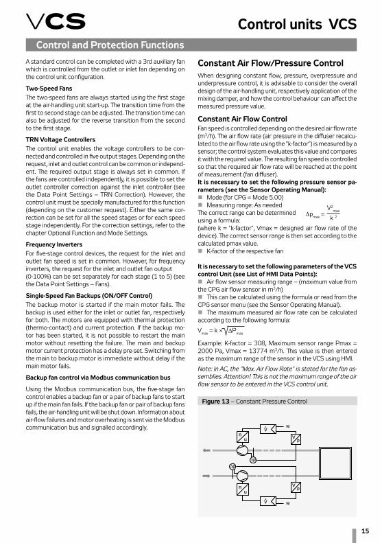
Constant Air Flow/Pressure ControlWhen designing constant flow, pressure, overpressure and underpressure control, it is advisable to consider the overall design of the air-handling unit, respectively application of the mixing damper, and how the control behaviour can affect the measured pressure value.
Constant Air Flow ControlFan speed is controlled depending on the desired air flow rate (m3/h). The air flow rate (air pressure in the diffuser recalcu-lated to the air flow rate using the "k-factor") is measured by a sensor; the control system evaluates this value and compares it with the required value. The resulting fan speed is controlled so that the required air flow rate will be reached at the point of measurement (fan diffuser). It is necessary to set the following pressure sensor pa-rameters (see the Sensor Operating Manual):n Mode (for CPG = Mode 5.00)n Measuring range: As neededThe correct range can be determined using a formula: (where k = "k-factor", Vmax = designed air flow rate of the device). The correct sensor range is then set according to the calculated pmax value.n K-factor of the respective fan
It is necessary to set the following parameters of the VCS control Unit (see List of HMI Data Points):n Air flow sensor measuring range – (maximum value from the CPG air flow sensor in m3/h)n This can be calculated using the formula or read from the CPG sensor menu (see the Sensor Operating Manual).n The maximum measured air flow rate can be calculated according to the following formula:
Vmax = k × DPmax
Example: K-factor = 308, Maximum sensor range Pmax = 2000 Pa, Vmax = 13774 m3/h. This value is then entered as the maximum range of the sensor in the VCS using HMI.
Note: In AC, the "Max. Air Flow Rate" is stated for the fan as-semblies. Attention! This is not the maximum range of the air flow sensor to be entered in the VCS control unit.
Dpmax = V2
max
k 2
Figure 13 – Constant Pressure Control

16
Basic Information on VCS Operating Modes
Operating states There are three operating states defined for VCS control units (Stop, Run, Auto):
Stop – The device is in standstill mode (fans stopped). Impor-tant safety features like antifreeze protection and moderate pre-heating of the water heater are retained.
Run – The device is started in accordance with the pre–set temperature mode and fan speed.
Auto – Control is switched to the next operating mode with a lower priority. The Auto operating state cannot be set in the time schedule mode because it is a control type with the lowest priority.
The operating mode determines which operating state will be active according to priorities (see Operating Modes).
Operating ModesThe control unit’s operating state (i.e. whether the air-handling unit is in the Stop or Run state) is determined by one of the operating modes (manual control, external control, HMI-SG controller, BMS or time schedule modes). HMI-DM or HMI-TM controllers affect control in the manual control mode. External control is performed by single- or two-contact control. BMS control enables control of the control unit by the higher level control device (e.g. smart building control systems; Note: pending). To control air handling systems, the HMI-SG control-ler is connected to the control unit.
The operating mode which will determine the device’s oper-ating state (Run or Stop) is determined by the priority. Each operating mode is assigned a priority, i.e. the first option to control the control unit, to eliminate mutual interference. The operating modes are prioritized as follows, from the lowest to highest priority:
n Manual control
n External control
n Local HMI-SG controller
n BMS (pending)
n Time schedule
n Additional operating modes
The priorities and entire control system are shown in the diagram on the following page.
Control and Protection Functions
Figure 14 – Constant pressure control
Constant pressure controlFan speed is controlled depending on the desired air pressure (Pa). The air pressure is measured by a sensor; the control system evaluates this value and compares it with the required value. The resulting fan speed is controlled so that the required air pressure will be reached at the point of measurement. It is necessary to set the following air flow sensor param-eters (see the Sensor Operating Manual):n Mode (for CPG = Mode 4.00)n Measuring range: As needed
It is necessary to set the following parameters of the VCS control Unit (see List of HMI Data Points):n Air pressure sensor measuring range – (maximum value from the CPG air pressure sensor in Pa)n Required values (separately for the inlet and out-let fans). 5 required values are available for selection. Constant Air Flow + Overpressure in the Room ControlThe inlet branch (fan) is adjusted to the constant air flow so that the required air volume is delivered to the room. The outlet branch is adjusted to the required difference in overpressure in the room. Thus, the outlet fan is adjusted to the required pres-sure (overpressure) depending on the pressure sensor location.Application: Preventing dirt from entering the room.
Constant Air Flow + Underpressure in the Room ControlThe outlet branch (fan) is adjusted to the constant air flow. The inlet branch (fan) is adjusted to the difference in under-pressure in the room. Thus, the inlet fan is adjusted to the required pressure (underpressure) depending on the pressure sensor location.Application: Preventing dirty air from entering the adjacent rooms
Note: When commissioning the system, it is necessary to perform the settings and regulation of the device (PID con-stants, FI ramp, etc.)
n Number of fans (for twins = 2). The air flow rate of one fan is measured and is then multiplied by the number of fans. n Required values (separately for the inlet and outlet fans)5 required values are available for selection.

17
Control units VCS
The fan speed control parameters are available through the HMI controller in the List of Data Points in the section Settings – Fans (inlet fan backup, outlet fan backup, TRN correction).
Air-Handling Unit Additional Operating ModesIf no operating mode is applied and the time schedule mode is in the Stop state, the air-handling unit can be started from additional operating modes. The user can use the following additional operating modes to start the air-handling unit: n Night chillingn Temperature start-upn Optimized startAdditional operating modes can be activated by the HMI-SG controller in the List of Data Points in the section Settings – Additional Operating Modes, Functions.
Control Application Starting Algorithm Air-handling system operation safety is assessed first (fire detection and operational safety of the air-handling devices). Then the operating modes and their priorities are assessed (Manual, External, HMI-SG controller, BMS and time modes). If no control mode is currently used, the air-handling unit can, but may not, be put into one of the additional operating modes de-pending on the user's option. All the operating modes and their correlation are shown in the figure # 10 - "Operating modes".The current operating mode can be monitored through the HMI controller in the List of Data Points in the section Moni-tor – Current Modes.When the fans run and the air-handling unit is in operation, two basic groups of parameters are used to control operation:n Temperature moden Fan output (speed) The fan output or speed can be set directly at levels corre-sponding to the air-handling system configuration:n Single-speed motor fans: >> Stage 1n Two-speed motor fans: >> Stage 1 / Stage 2n All five-stage controlled fans: >> Stage 1 / Stage 2 / Stage 3 / Stage 4 / Stage 5
See the chapter Fan Speed Control.
Figure 13 – Operating modes
Alarm A
State
Yes
No
Stop
Stop,Co1,EC1,...ManualCo1,EC1,Co2, ...
RUN
Co1,EC1,Co2, ...
HMI-SG (p. 125) HMI TM, DM
Fans (stage 1-5)
Comfort/Economy
Auto
Auto
Auto
Auto
Stop
Passive
Active
Passive
Active
Passive
Active
Passive
External control
Optimized start
HMI-SG contr.
BMS
Time modes
Optimized start
Temperature start-up
Night chilling
Night turning
Temperature start-up
Night chilling
STOP
Night turning
Additional Operating Modes

18
Night ChillingDuring night chilling, cold outdoor air is used to cool internal rooms of the buildings, thus excess heat accumulated in buildings during the day in summer months is removed. Night chilling minimizes the use of cooling devices and reduces the energy demand for temperature control day hours. During night chilling, the inlet and outlet dampers are fully open and fans run in the highest output stage. Night chilling start-up is enabled 12 hours before activation of the selected time schedule.
Activation When the following conditions are fulfilled simultaneously:n TVEN > TMIN n TVEN < TPRO - ∆n TPRO > TŽÁD + THYS
Termination If one of the following conditions is fulfilled:n Once minimum operating time has elapsed while no time mode is active (Stop mode)n TVEN > TPRO - 1n TPRO <= TŽÁD TMIN Minimum outdoor temperature; TVEN Outdoor air temperature; ∆ Outdoor and indoor temperature difference TŽÁD Required room temperatureTHYS Temperature hysteresis
Temperature Start-UpThis feature prevents the building from overheating or over-cooling. The energy used to maintain a constant temperature range and system temperature oscillations are lower than the energy consumption for overheated or overcooled room control. Air from the room is re-circulated through the air mix-ing section (mixing damper fully open). The fan speed is set to the highest output stage. During temperature start-up, it is possible to select whether the inlet and outlet dampers or dampers along with the outlet fan will be blocked. This can be performed using the HMI controller, refer to the chapter Additional Operating Mode and Function Setting Options.
Cooling
Activation When the following conditions are fulfilled simultaneously:n TPRO > TS,CH n Once the tBL time interval has elapsed
TerminationIf the following condition is fulfilled:n TPRO < TS,CH - THYS
Heating
Activation When the following conditions are fulfilled simultaneously:n TPRO < TS,O n Once the tBL time interval has elapsed
Additional Operating ModesTerminationIf the following condition is fulfilled:n TPRO > TS,O + THYS
TPRO Required room temperatureTS,CH Starting temperature for coolingTS,O Starting temperature for heatingTHYS Temperature hysteresis at the stoptBL Heating blocking timetBEH Time remaining to start the time schedule
Optimized StartThis feature is used to ensure the comfortable temperature to be reached before the time schedule has been activated. Thus possible initial temperature non-conformities after the time schedule activation are removed. This feature includes the setting for the room ventilation to have the room temperature controlled as soon as possible. This is based on air recirculation within the room along with cooling or heating adjustment. The mixing damper is fully open.It is possible to select whether the inlet and outlet dampers will only be blocked or whether the outlet fan will be blocked as well.
Cooling
Activation When the following conditions are fulfilled simultaneously:n TPRO > TS,CH + THYS n t∆TP < tKOM
TerminationIf the following condition is fulfilled:n TPRO < TS,CH
Heating
Activation When the following conditions are fulfilled simultaneously:n TPRO < TS,O - THYS n t∆TP < tKOM
Termination If the following condition is fulfilled:n TPRO > TS,O
TPRO Required room temperatureTS,CH Required temperature set-point for coolingTS,O Required temperature set-point for heatingTHYS Temperature hysteresistKOM Pre-set interval before time program start-upt∆TP Time remaining to the time program start-up
Night Turning FeatureWhen the supply air temperature sensor is not present, the outlet air temperature is evaluated. As the temperature is measured in the outlet, the fans are started at specified time intervals and air from the room is drawn into the outlet duct. The night turning feature is used along with the night chilling or temperature start-up modes. Night turning can be specified by the turning start time, time remaining to next turning and turning duration time.

19
Control units VCS
Temperature modesThe VCS control unit system offers the possibility to maintain the controlled room or supply air temperature using two user adjustable temperature modes: n Comfortable (normal mode usually used for temperature control)n Economy (e.g. night moderate heating)
Temperature modes are defined by the levels and staging of the required temperature set-points, respectively the tem-perature difference (systems with heating and cooling) – i.e. according to the environment comfort. They also affect the operating energy demand. Each temperature mode is defined by the temperature settings for heating (lower environment temperature limit – minimum temperature) and the tempera-ture settings for cooling (upper limit – maximum temperature). The area of maintained controlled temperature ("dead zone") lies between these temperature set-points. Of course, main-taining the pre-set temperatures is dependent on the correct dimensioning of heating or cooling systems. Temperature modes are correlated so that the less comfortable mode has the required temperature:
n For heating, the required temperature (lower limit) is always lower than (or the same as) the more comfortable mode.n For cooling, the required temperature (upper limit) is always greater than (or the same as) the more comfortable mode
For more comfortable modes in systems with both heating and cooling, the environment temperature "dead zone" is always narrower (or the same). Temperature modes are pre-set, see Data Points, Setting – Temperature Modes. Note: The system automatically monitors the above-men-tioned temperature correlation and immediately adjusts the information about the possible maximum and minimum of each value depending on the user settings.
WarningSettings, respectively the control process, also affect the correction values.
Time modesThe VCS control unit system provides the possibility to control operation depending on pre-set time schedules (modes). n Daily schedule – allows max. 6 changes per day (mode with the lowest priority) n Weekly schedule – allows max. 7 changes per week n Exception schedule – allows max. 10 changes per weekSwitch-off schedule – allows max. 10 changes (mode with the highest priority)These modes interact, applying the system priorities. At any time, the air-handling operation is always controlled by the time schedule with the highest priority provided that it has an active time interval for that moment. The weekly and daily schedules can be overridden by the exception schedule or switch-off schedule at any time. The daily schedule is arranged for each day of the week. The weekly schedule is the same for each week of the year. Requirements for specific days (e.g. holidays) must be sched-uled within the exception time schedule.
Temperature modes, Time modesThe following parameters are set for the weekly and daily schedules: n Start time (= end of previous interval) n Fan output (speed) stages n Temperature modeThe exception and switch-off schedules can be set for:n Date – day of the weekn Range of days – a period (e.g. holiday)n Week – days of the week (Monday, Tuesday,…)
The default setting is weekly and daily time schedule.Temperature modes in weekly and daily time schedules can be set using the HMI-SG controller in List of Data Points in the Settings section – Temperature modes, the chapter Control (HMI-SG controller). The exception and switch-off schedules can be set using HMI-DM, HMI-TM or HMI@Web controllers.
Date
Starting day: *,01.01.12 1st January 2012 is the specific day of operation.
Starting day: Mo,*.*.** Every Monday is the specific day of operation.
Starting day: *,*.Even.** Every even month (February, April, June,…) is the specific month of operation in each year.
Range of Days
Starting day: *,23.06.12 End: *,12.07.12
Days from 23rd June 2012 to 12th July 2012 are the specific days of operation in the year.
Starting day: *,23.12.** End: *,31.12.**
Days from 23rd to 31st December are the specific days of operation in each year.
Starting day: *,23.12.11End: *,01.01.12
Days from 23rd December 2011 to 1st January 2012 are the specific days of operation.
S t a r t i n g d a y : * , * . * . * * End: *,*.*.**
An exception time schedule or a switching off schedule is perma-nently active and the weekly program will not be applied!
Week
Day of the week: *,fri,* Every Friday is the specific day of operation
Day of the week: *,Fri,Even Every Friday in an even month (Febru-ary, April, June,…) is the specific day of operation
Day of the week: *,*,* When the starting day is entered in this way, an exception time schedule or a switching off schedule is perma-nently active and the weekly program will not be applied!
Day of the week: 2.,*,* The second week of every month is the specific day of operation.
Time Schedule Operating Settings

20
The HMI-SG (Human Machine Inter-face) enables full control and moni-toring of the equipment’s operating parameters. The air-handling unit parameters can be accessed through the List of Data Points, which is pro-tected by the password applicable for the corresponding access level.
Control (HMI-SG)
HMI-SG controller enables the following items to be reviewed:
n Room (outlet) temperature n Current air-conditioning process (cooling, heat recovery,
mixing or heating) n Temperature mode (Economy, Comfort) n Current system time and day of the week n Fan output stage
Other information is available via the List of Data Points, see the chapter Data Point List Access and Editing. The HMI-SG POL822.60/STD hand controller is used to control air-handling devices. This controller can be connected to the POL 4xx or POL 6xx master controller (respective to the terminals ready in the control unit).
Operating conditionsDegree of protection: IP 30 Permissible ambient temperature: 5 °C to 40 °C Relative humidity < 85 %
Warning:To avoid unintentional unit start-up, the master switch must be switched off and locked when repairing the VCS unit.
Wiring and InstallationThe HMI-SG controller is connected to the Process Bus (KNX). A twin cable or a twisted pair of leads can be used to perform the connection to the KNX bus.
Function ButtonsThe room unit consists of the face plate and back cover, which can be separated. There are 8 function buttons on the controller's face plate.
Figure 14 – Connection to the control unit
Figure 15 – HMI-SG controller
Controller DescriptionTable 3 – Function Buttons descriptionButton number Icon Name Function description
T1 Power Air-handling unit start or stop
T2 Presence not used
T3 Program
The time schedule button: by holding this button, you can set the date; by pressing this button, you can set the desired temperature mode timing and required fan output stage
T4 MinusTemperature correction – pre-set depending on the selected temperature mode
T5 PlusTemperature correction – pre-set depending on the selected temperature mode
T6 OK Confirmation of the date or time schedule settings
T7 Fan
Fan output (speed) stage setting; each button cyclically increases the setting by one stage. The cur-rent output stage is displayed on the display
T8 Mode
Temperature mode selection (Auto, Comfort and Economy). By pressing the button, the modes can be cycled. The currently selected temperature mode is indicated by an icon on the display
Master controller
Process Bus
HMI-SG 1 HMI-SG 2
Local HMI-SG controller Figure 15 – Wiring box installation
The controller can be installed using a wall wiring box or embedded in plaster. The maximum distance between the control unit and room controller is up to 700 m.HMI-SG controllers are connected to the master controller in series and wiring is always performed to one point.
Note: The Installation Instructions are part of the HMI-SG controller delivery.

21
Control units VCS
Designation Level Password (factory setting)
S SERVICE 4444
A ADMINISTRATOR 3333
U USER 2222
G HOST 0000
Control (HMI-SG)
User Roles and General SpecificationThe device parameters (data points) are structured and made available to users in accordance with their user roles (access levels). These roles must be assigned to the users by the system administrator according to their expertise and responsibility for device operation.
n Guest – allows only common parameters to be viewed. n User – allows common parameters to be viewed and
controlled, as well as start and stop of the device. n Administrator – allows the system administrator to view and control common and some special parameters, pre-set operating parameters and modes for the user.n Service – an access level recommended only for the sup-plier or authorized service provider. In addition to the admin-istrator's level, it allows the user to adjust highly specialised configuration parameters related to the air-handling system and its instrumentation, control constants, water heater protection parameters, etc.
HMI to VCS System Access Default (factory) SettingsA control using the HMI controller uses an access right struc-ture in accordance with the concept of structured access of the air-handling device, refer to the chapter Overview and List of Date Points, Factory Settings.The HMI controller allows only four passwords (always four-digit and numerical) to be set, each for a different access level.Factory set default rights to access the VCS control unit using the HMI controller:
Table 4 – Display description
Table 5 – access levels
Icon Display Description
I1
Indication of room temperature or correction of the required temperature in °C or °F
Room temperature in °C (increment 0.1 °C)
Room temperature in °F (increment 0.5 °F)
Required temperature correction in °C or °F
I2 Time
I3 Fan output (speed) stage
I4 Days of the week
I5 On/Off
I6 Mode Auto
I7 Temperature mode Economy
I8 Temperature mode Comfort
I9 Cooling sequence
I10 Heating sequence
I11 Humidification
I12 Fan Speed Compensation
I13 Mode Presence (this mode is not used as standard)
I14 Recovery and mixing sequences – energy savings
I15 Alarm
I16 Data point editing
Warning: n When commissioning the device, we strongly recom-
mend changing the factory settings according to user needs to maintain the safety of the device itself as well as the controlled process.
n It is advisable to note and store the Service and Adminis-trator passwords in a suitable (confidential) place (or up-date them upon each change to settings) to have easy access to them and thus maintain access to the system at the Service and Administrator levels.
n If the Service password changed from the factory setting is lost (forgotten), it is necessary to contact the man-ufacturer's representative. The lost Administrator lev-el password can be retrieved by the user of the Service level (usually the supplier, installer or M&C service com-pany).
n The changed password settings cannot be automatically restored (reset, etc.) to the factory settings.
n The user of the SERVICE level can change the passwords of all other user levels, the user of the ADMINISTRATOR level can change the passwords of the GUEST and USER levels while users of the USER or GUEST levels are not allowed to change any passwords.

22
Data Point List Access and EditingAn overview of the structure of parameters accessible via the HMI-SG controller is available in the List of Data Points upon logging in using the appropriate access right level. The data points for writing and reading are assigned different access right levels. The procedure for access for editing and reading of data points is as follows:
1) The edit mode is signalled by an icon (I16). This mode can be accessed by pressing the Plus (T5), Minus (T4) and Mode (T8) buttons simultaneously. The cur-sor flashes in the first position from the left, ready for the 1st password digit to be entered. Change the value of the digit by pressing the Plus (T5) or Minus (T4) button and confirm by press-
ing the Mode (T8) button and the cursor will move to the next position. The password is activated after entering and confirm-ing the last digit of the password by pressing the T8 button.
2) Upon entering the correct password, the data points for the respective access level (pass-word) are displayed.
Note: If the entered password is wrong, "---" will be displayed.
3) Using the Plus (T5) or Minus (T4) buttons, select the first num-ber of the data point group and confirm the selection by pressing the mode (T8) button. Then select a desired data point within the group in the same way as the first number of the data point group. The number on the first line rep-resents a data point code while the number on the second line represents its value.
4) If the parameter value is highlighted, the data point is only for reading. If the parameter value flashes, the data point can be edited in accordance with the access level you logged in at.
5) The value can be edited by the Plus (T5) or Minus (T4) but-tons. To confirm changes to the value, press the Mode (T8) button. Upon confirming the changes, the data point cursor will start to flash, and you can move to the next parameter in the group. Another group of parameters, i.e. return to a higher level, can be made by pressing the Power (T1) button.
Note: If no change is made within 1 minute, the data point editing mode will be exited.
Control (HMI-SG)
Communication SettingsOnce the HMI-SG controller has been connected to the control unit, the communication between both devices will be set automatically. If two HMI-SG controllers have been connected to the control unit, it is necessary to set a new address for one of the controllers. An interface for the communication settings will be displayed on the controller, and then parameter #7 must be changed. 1) The interface for the communication settings is displayed by pressing and holding the Power (T1), Mode (T8), Minus (T4) and Plus (T5) buttons simultaneously. The cursor flashes in the first position from the left, ready for the 1st password digit to be entered. Change the value of the digit by pressing the Plus or Minus (T4) button and confirm by pressing the Mode (T8) button and the cursor will move to the next position. Changes to the parameter settings can only be made by the ADMINISTRATOR, SERVICE or USER role users. 2) After a correct password has been entered, press the Mode (T8) button to enter the interface for changes to parameter settings.3) Use the Plus (T5) or Minus (T4) buttons to browse the communication parameters. Press the Mode (T8) button to confirm selection of the desired parameter (parameters for communication settings are listed in the following table).
Table 6 – Communication settings
Parameter number/Description
001KNX connection state• OK – bus communication is OK• NF – no bus communication
002 Physical address (X.1.1)X…value range 0 to 15; generated automatically
003Physical address (1.X.1)X…value range 0 to 15; generated automatically
004 Physical address (1.1.X)X…value range 0 to 252; generated automatically
005
Byte (program) address (X.1.1)X…value range 0–126 (pre-set value is 5)This value needs to be changed if several master contro-llers are connected to the KNX bus by several controllers
006 Room (program) address (1.X.1) X…value range 1 to 14 (pre-set value is 1)
007
Zone (program) address (1.1.X)X…value range 1 to 15 (pre-set value is 1) This value must be changed from 1 to 2 if 2 control-lers are connected to the same master controller.
008Network failure detection enabledNetwork failure detection enabled or disabled; network failure is indicated by the word "NET".
009
Physical address automatic assignment (pre-set value is 1)0…Room unit uses firmly defined physical address1…automatic generation of the controller's address

23
Control units VCS
Figure 16 – HMI-SG controller LCD display
I6
I3
I1
I2
I4
Operating the HMI-SG controllerIf only one HMI-SG controller is connected to the control unit, it then serves as an operating controller for full setting and control of the control unit. During the first start-up of the air-handling unit, the manual operating mode (the highest priority) is set to the Stop state, and the HMI-SG controller does not interfere with control of the control unit. In the Manual operat-ing mode, it is necessary to change the state from Stop to Auto using data point #125 and thus move the priority from the control unit to the HMI-SG controller's operating mode.
First Control Unit Start-Up Using HMI-SG Controller1) Press the Plus (T5), Minus (T4) and Mode (T8) buttons simultaneously to display the log-in screen for the 4-digit password. Change the value of the digit by pressing the Plus (T5) or Minus (T4) button. Press the Mode (T8) button to confirm the entered digit and the cursor will move to the next position. Once the correct password has been entered, the data point screen will be displayed. Press the Power (T1) button to leave the log-in interface.
2) The first digit "0--" will be displayed. To change the first digit value, press the Plus (T5) or Minus (T4) button. To confirm the entered value, press the Mode (T8) button.
Use the Plus (T5) and Minus (T4) buttons to set the last two digits to get the string "125". To confirm the entered value, press the Mode (T8) button. To return to the previous step, press the Power (T1) button.
3) The flashing number on the second line represents a data
point value. Use the Minus (T4) buttons to change the data point value from "1" to "0" and confirm by pressing the Mode (T8) button. To return to the previous step, press the Power (T1) button.
The situation before initiating the control unit from the HMI-SG controller is illustrated in figure 16. The Stop operating mode is indicated by the Auto icon (I6). Current temperature (I1) and system time (I2) are displayed. The fans are not running (I3). The day of the week is indicated by digits (1–7) in the lower part of the display.
Note: 12h/24h system time format cam be changed using data point 898. The source of the displayed temperature can be selected using data point 887.
Control (HMI-SG)4) The cursor with the communication parameter value will start to flash. The parameter value can be changed by pressing the Plus or Minus (T4) buttons. Press the Power (T1) button to confirm the change to the communication parameter value.5) To return to a higher level, press the Power (T1) button. If no change is made within 1 minute, the interface will be exited.Note: If the air-handling unit is controlled by two HMI-SG controllers, the last change made from one of the control-lers will be valid.
System Date and Time SettingsHere, the actual VCS system date and time can be set – these setting are required for correct functioning of the time schedule programs. The procedure for system date and time setting is as follows:After long hold the Program (T3) button to set the date and time. Press the Plus (T5) and Minus (T4) buttons to change the date and time values. Press the OK (T6) button to confirm the changes and the cursor will move to the next item. The cursor cycles through the following items:
Hour → Minute → Month → Day → Year
Default Application ParameterizationTo ensure comfortable and economy operation requiring mini-mum attendance, it is necessary to perform the main settings defining the parameters and air output, respectively the tem-perature control, and stability in the ventilated/air-conditioned room. Data points must be set for all the relevant parameters:
n Temperature modes n Time schedules n Control parameters n Correction values n Antifreeze Protection n Control constants n Optional modes and functions
The parameters are described in the chapter List of Data Points, Factory Settings.

24
Control (HMI-SG)
Operating Screen (Examples)After making the HMI-SG controller a service controller, it is possible to change the control unit settings. Use the Mode (T8) button to manually switch between the Run state with temperature modes (Comfort or Economy) and the Auto state. Use the Power (T1) button to put the air-handling unit into the Stop operating state, the display in the HMI-SG operating mode will only display the ON/OFF icon (I5).
Operating State Auto The fan speed and temperature mode are set depending on the time schedule compilation. It is possible to set a correc-tion to the required temperature, see the chapter Required Temperature Correction. It is also possible to adjust the time schedule, see the chapter Daily (Weekly) Time Schedule.
The figure shows the Auto operating state display. The state is signalled by an icon (I6). The air-handling unit is controlled in accordance with the time schedule. The moderate heating temperature mode (I7) with a cooling sequence (I9) is active. The fans are set to the second speed stage (I3). Apart from the cooling sequence, the heating (I10), heat recovery and mixing
(I14) icons can be displayed.
The figure shows the situation where a time schedule con-trolled air-handling unit is in the Stop operating state. The fans are not running (I3). No temperature modes or heating or cooling sequences are active.
Warning: Current additional operating mode stats are not displayed but can be monitored in the List of Data Points in the
section Monitor – Current Modes – Current Modes – Current operating Mode.
Manual Operating Mode (Run)In Manual operating mode, it is possible to select the required temperature mode, set any fan speed output stage and the required temperature correction.
This display shows the manually selected Comfort tem-perature mode (I8) with a heating sequence (I10) and the fourth fan speed stage. In Manual mode, the fan speed can be set using the Fan button (T7). To manually switch between the temperature modes, use the Mode (T8) button.
Failure DetectionIf a failure of external components
I6
I8
I3
I3
I9
I9
I7
connected to the device failure detection inputs (incorrect state of the contact) occurs, the VCS control unit will au-tomatically put out an alarm in accordance with an internal algorithm – indicating the faulty object and in case of severe failures stopping the air-handling unit. Each failure is more closely specified by a failure class. The failure class determines the severity of the failure. A class failures will shut down the air-handling unit. B class failures will deactivate some system functions (e.g. compensation if the temperature sensor fails) but they will not shut down the air-handling unit. Numerical failure codes specifying the failure events are listed in the chapter Failures. If more failure events occur, the number of the failure with the highest priority (the most serious failure) will be displayed.
Failure Screen (example)If a failure occurs, the air-handling unit is put in the STOP state (respectively the Run mode is retained, B class failure). This is
indicated by flashing Auto (I6) and Alarm (I15) icons on the display. The failure class (I18) and number (I19) are displayed below the temperature indication. Indication of the alarm will cease shortly after all failure events have been removed. The number shown on the display can also be accessed via data point 824.
Failure ResetFailure reset can only be performed once the cause of the failure has been identified and removed. The failures are reset using data point 825.
Required Temperature Settings in Temperature ModesRequired temperature settings for the Comfort and Economy temperature modes are performed in the List of Data Points –Temperature Modes:
n 101 – Comfort cooling n 103 – Comfort heatingn 105 – Economy coolingn 107 – Economy heating
Required Temperature CorrectionThe pre-set required temperatures in each temperature mode can be changed within ±3 °C directly from the HMI-SG controller. Use the Plus (T5) button to increase the required temperature or use the Minus (T4) button to decrease the required temperature. The one button pressing increment or decrement value can be set in data point 897. This tempera-ture adjustment is only valid for a current mode. Upon transi-tion between modes, this correction will be reset.
I6
I15
I19
I18

25
Control units VCSControl (HMI-SG)
Time Schedule Compilation Procedure 1) Press the Program (T3) button to enter the time schedule configuration menu for each day of the week.B HMI SG displays the first day of the week, i.e. Monday. Up to 6 time windows ((1-1 to 1-6) can be set for each day.3) The Mode (T8) button enables you to select a day by cycling through the week days (1-2-3-4-5-6-7-A). The "A" option is used to set the time schedule for business days (1 – 5) simultane-ously. If you make any change to the "A" time schedule, the settings of the "A" day will be copied to all business days.4) The Power (T1) button is used to assign the selected time window with an operating mode (Stop-Economy-Comfort).5) The Fan (T7) button is used to set the fan operation speed stage (st. 1 – st. 5).6) The Minus (T4) and Plus (T5) buttons are used to set the beginning of the time window; to confirm the time setting, press the OK (T6) button. 7) Once the beginning of the time window has been set, move to the next settings in the time window. 8) If you set the beginning of the time window to "--:--", the window will be disabled.9) Press and hold the OK (T6) button to go back one step in the time schedule settings within the set time.10) Press and hold the Fan (T7) button to go back one step in the time schedule settings within the fan speed stage settings.11) Press and hold the Mode (T8) button to move one step back (a weekday selection).12) Press the Program (T3) or Presence (T2) button to exit the Time Schedule Settings menu.13) If no settings are performed in the time schedule within 1 minute, the menu will be automatically left..
time window
fan speed stage setting (T7)
operating mode setup (T1)
time setup (T4), (T5)
Quick Menu: This enables quick access to the temperature and selected value monitoring without editing.Use the Minus (T4) and Plus (T5) to switch between the temperature values.Use the Program (T3) or Presence (T2) buttons to exit the Quick Menu. Only those values which are included within the given version of the VCS unit are displayed.Briefly press the OK (T6) button to display the values listed below:n Inlet temperature (Sply) n Outdoor temperature (Out)
Press and hold the OK (T6) button to display the values listed below:n Comfort temperature mode (heating) n Economy temperature mode (heating)n Comfort temperature mode (cooling) n Economy temperature mode (cooling)
Lock/Unlock the SG II buttonsPress and hold the Presence (T2) button to lock/unlock the SG II controller in order to prevent unauthorised access to the device control.
n Return water temperature (Htr)n Outlet temperature (Rtrn)n Room temperature (Room)

26
Control (HMI-SG)
Additional Operating Modes and Function SettingsAdditional operating modes and functions can be activated in the List of Data Points in the section Settings – Additional Operating Modes, Functions. Once the respective mode or function has been set, it is necessary to perform SW reset using a specific data point 211 (Reset after the configuration of additional modes/functions).
Optional Additional Operating Modesn Night Chillingn Temperature start-Upn Time mode start optimization
Optional additional functionsn Outdoor Temperature-Dependent Fan Speed Compensa-tionn Heating/cooling dependent fan speed compensationn Room (Outlet) Temperature-Dependent Fan Speed Com-pensationn Humidity-dependent Fan Speed Compensationn Air Quality-Dependent Damper Position Compensationn Heating/cooling–dependent fan speed compensation – cooling sequencen Cooling using heat recovery with rotary regenerator option or using mixing dampern Heating and mixing sequence ordern Outlet fan correction – using five-stage control (TRN controllers)n Difference between required and actual temperature monitoringn Damper and outlet fan blockingn Room temperature measuring point selection
User Settings Backup and Recovery It is advisable to perform backups especially before significant changes in control parameter settings (PID controller fac-tors, temperature setting for compensations or starting of the optional additional modes), or always when the control works optimally. Data backup or recovery can be performed using the HMI controller in the List of Data Points, section Checks – User Settings.
List of Data Points, Factory Settings Warning:The device parameters are structured and made available to users in accordance with their user roles (access levels). These roles must be assigned to users by the system administrator according to their expertise and responsibility for device opera-tion. Access to the data points is also limited by the user role level – for levels lower than Service, not all parameters (data points) are displayed, respectively, they can be read without being able to change (save) them. The Parameter List with a combination of all possible air-handling unit applications is in-cluded in the List of data points under the highest access right.

27
Control units VCSList of Data Points (HMI-SG controller)
Monitor
Temperature °C
001 G Temperature in the inlet °C
002 G Temperature in the room 1 °C
003 G Temperature in the room 2 °C
004 G Room unit 1 °C
005 G Room unit 2 °C
006 G Temperature in the outlet °C
007 G Outdoor temperature °C
008 G Return water temperature °C
009 G Heat exchanger freezing temperature °C
010 G Electric preheater temperature °C
011 G Water preheater temperature °C
012 G Electric reheater temperature °C
013 G Flue gas temperature °C
014 G Final room temperature (controlled) °C
Humidity015 G Inlet air relative humidity %r.H.
016 G Room air relative humidity %r.H.
017 G Outdoor air relative humidity %r.H.
Pressure
018 G Pressure in the inlet Pa
019 G Pressure in the outlet Pa
020 G Air flow rate in the inlet m3/h
021 G Air flow rate in the outlet m3/h
CO2 (VOC, CO)022 G CO2 (VOC, CO) concentration ppm
Performances
023 G Inlet fan output % (m3/h, Pa)
024 G Outlet fan output % (m3/h, Pa)
025 G 3rd fan output %
026 G Outlet level for the electric reheater %
027 G Heating mixing set valve position %
028 G Outlet level for cooling %
029 G Cooling output (stage)
030 G Electric preheater position %
031 G Outlet level for the electric heater %
032 G Heat pump output %
033 G Outlet position to the mixing damper %
034 G Heat exchanger control outlet position %
035 G Modulation burner outlet position %
036 G By-pass damper outlet position %
Operating states037 G Fan state 0 -
1 Stage 1
2 Stage 2
3 Stage 3
4 Stage 4
5 Stage 5
038 G Electric pre-heater state 1 off
2 on
039 G Water pre-heater state 0 off
1 on
040 G Electric re-heater state 1 off
2 on
041 G Water heater pump state 0 off
1 on
042 G Pre-heating function of water heating 0 off
Menu HMI-SGParameter
MeaningFactory Settings
Notation Reading Value Min Max
code level code level
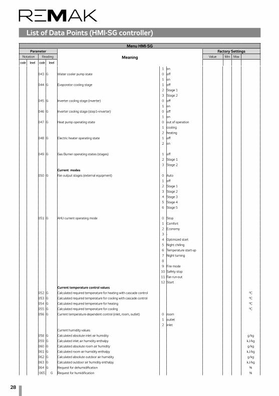
28
List of Data Points (HMI-SG controller)
Menu HMI-SGParameter
MeaningFactory Settings
Notation Reading Value Min Max
code level code level
1 on
043 G Water cooler pump state 0 off
1 on
044 G Evaporator cooling stage 1 off
2 Stage 1
3 Stage 2
045 G Inverter cooling stage (inverter) 0 off
1 on
046 G Inverter cooling stage (step1+inverter) 0 off
1 on
047 G Heat pump operating state 0 out of operation
1 cooling
2 heating
048 G Electric heater operating state 1 off
2 on
049 G Gas Burner operating states (stages) 1 off
2 Stage 1
3 Stage 2
Current modes
050 G Fan output stages (external equipment) 0 Auto
1 off
2 Stage 1
3 Stage 2
4 Stage 3
5 Stage 4
6 Stage 5
051 G AHU current operating mode 0 Stop
1 Comfort
2 Economy
3 -
4 Optimized start
5 Night chilling
6 Temperature start-up
7 Night turning
8
9 Fire mode
10 Safety stop
11 Fan run-out
12 Start
Current temperature control values
052 G Calculated required temperature for heating with cascade control °C
053 G Calculated required temperature for cooling with cascade control °C
054 G Calculated required temperature for heating °C
055 G Calculated required temperature for cooling °C
056 G Current temperature-dependent control (inlet, room, outlet) 0 room
1 outlet
2 inlet
Current humidity values
058 G Calculated absolute inlet air humidity g/kg
059 G Calculated inlet air humidity enthalpy kJ/kg
060 G Calculated absolute room air humidity g/kg
061 G Calculated room air humidity enthalpy kJ/kg
062 G Calculated absolute outdoor air humidity g/kg
063 G Calculated outdoor air humidity enthalpy kJ/kg
064 G Request for dehumidification %
065 G Request for humidification %
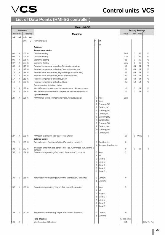
29
Control units VCSList of Data Points (HMI-SG controller)
Menu HMI-SGParameter
MeaningFactory Settings
Notation Reading Value Min Max
code level code level
066 G Humidifier state 0 off
1 onSettings
Temperature modes
101 A 102 G Comfort - cooling 24.6 0 99 °C
103 A 104 G Comfort - heating 22.6 0 99 °C
105 A 106 G Economy - cooling 28 0 99 °C
107 A 108 G Economy - heating 20.6 0 99 °C
109 A 110 G Required temperature for cooling, Temperature start-up 15 -64 64 °C
111 A 112 G Required temperature for heating, Temperature start-up 25 -64 64 °C
113 A 114 G Required room temperature , Night chilling (control for inlet) 22 -64 64 °C
115 A 116 G Required room temperature , Boost (control for inlet) 20 -64 64 °C
117 A 118 G Required temperature for cooling, Boost 15 -64 64 °C
119 A 120 G Required temperature for heating, Boost 25 -64 64 °C
Cascade control limitation - limiter
121 S 122 A Max. difference between room temperature and inlet temperature 10 0 64 °C
123 S 124 A Min. difference between room temperature and inlet temperature 10 0 64 °C
Operation mode
125 A 126 G AHU manual control (Temperature mode, fan output stage) 0 Auto Stop
1 Stop
2 Economy; St1
3 Comfort; St1
4 Economy; St2
5 Comfort; St2
6 Economy; St3
7 Comfort; St3
8 Economy; St4
9 Comfort; St4
10 Economy; St5
11 Comfort; St5
127 A 128 G AHU start-up time-out after power supply failure 10 0 9999 s
External control
129 U 130 G External contact function definition (Ext. control 1 contact) 0 Start function 0
1 Start and Stop function
131 U 132 G Transition time from ext. control mode to AUTO mode (Ext. control 1 contact) 0 0 23 h
133 U 134 G Fan output stage setting (Ext. control 1 contact or 2 contacts) 0 Auto 2
1 off
2 Stage 1
3 Stage 2
4 Stage 3
5 Stage 4
6 Stage 5
135 U 136 G Temperature mode setting (Ext. control 1 contact or 2 contacts) 0 Comfort 0
1 Economy
137 U 138 G Fan output stage setting "Higher" (Ext. control 2 contacts) 0 Auto 5
1 off
2 Stage 1
3 Stage 2
4 Stage 3
5 Stage 4
6 Stage 5
139 U 140 G Temperature mode setting "Higher" (Ext. control 2 contacts) 0 Comfort 0
1 Economy
Fans - Modbus Control limits
141 A Inlet fan output St1 setting 0.1 % (m3/h, Pa)

30
List of Data Points (HMI-SG controller)
Menu HMI-SGParameter
MeaningFactory Settings
Notation Reading Value Min Max
code level code level
142 A Inlet fan output St1 setting (a factor of 10) % (m3/h, Pa)
143 A Inlet fan output St2 setting 25 % (m3/h, Pa)
144 A Inlet fan output St2 setting (a factor of 10) % (m3/h, Pa)
145 A Inlet fan output St3 setting 50 % (m3/h, Pa)
146 A Inlet fan output St3 setting (a factor of 10) % (m3/h, Pa)
147 A Inlet fan output St4 setting 75 % (m3/h, Pa)
148 A Inlet fan output St4 setting (a factor of 10) % (m3/h, Pa)
149 A Inlet fan output St5 setting 100 % (m3/h, Pa)
150 A Inlet fan output St5 setting (a factor of 10) % (m3/h, Pa)
151 A Outlet fan output St1 setting 0.1 % (m3/h, Pa)
152 A Outlet fan output St1 setting (a factor of 10) % (m3/h, Pa)
153 A Outlet fan output St2 setting 25 % (m3/h, Pa)
154 A Outlet fan output St2 setting (a factor of 10) % (m3/h, Pa)
155 A Outlet fan output St3 setting 50 % (m3/h, Pa)
156 A Outlet fan output St3 setting (a factor of 10) % (m3/h, Pa)
157 A Outlet fan output St4 setting 75 % (m3/h, Pa)
158 A Outlet fan output St4 setting (a factor of 10) % (m3/h, Pa)
159 A Outlet fan output St5 setting 100 % (m3/h, Pa)
160 A Outlet fan output St5 setting (a factor of 10) % (m3/h, Pa)
161 A 162 U 3rd fan output St1 setting 0.1 0.1 100 %
163 A 164 U 3rd fan output St2 setting 25 0.1 100 %
165 A 166 U 3rd fan output St3 setting 50 0.1 100 %
167 A 168 U 3rd fan output St4 setting 75 0.1 100 %
169 A 170 U 3rd fan output St5 setting 100 0.1 100 %
171 A 172 U Fan run-out after unit stop shut-down 180 0 9999 s
Inlet backup – single-speed motors
173 A 174 U Failure flow evaluation time-out after main fan start-up 180 0 9999 s
175 A 176 U Failure flow evaluation time-out after backup fan start-up 180 0 9999 s
181 U Information – backup activation 0 non-activated
1 activated
Outlet backup - single-speed motors
177 A 178 U Failure flow evaluation time-out after main fan start-up 180 0 9999 s
179 A 180 U Failure flow evaluation time-out after backup fan start-up 180 0 9999 s
182 U Information - backup activation 0 non-activated
1 activated
TRN correction
183 A 183 A Common for all operating stages St 0 - 4 stages 0
1 - 3 stages
2 - 2 stages
3 - 1 stage
4 0
5 + 1 stage
6 + 2 stages
7 + 3 stages
8 + 4 stages
184 A 184 A For operating stage St1 0 - 4 stage 0
1 - 3 stage
2 - 2 stage
3 - 1 stage
4 0
5 + 1 stage
6 + 2 stages
7 + 3 stages
8 + 4 stages

31
Control units VCSList of Data Points (HMI-SG controller)
Menu HMI-SGParameter
MeaningFactory Settings
Notation Reading Value Min Max
code level code level
185 A 185 A For operating stage St2 0 - 4 stage 0
1 - 3 stage
2 - 2 stage
3 - 1 stage
4 0
5 + 1 stage
6 + 2 stages
7 + 3 stages
8 + 4 stages
186 A 186 A For operating stage St3 0 - 4 stage 0
1 - 3 stage
2 - 2 stage
3 - 1 stage
4 0
5 + 1 stage
6 + 2 stages
7 + 3 stages
8 + 4 stages
187 A 187 A For operating stage St4 0 - 4 stage 0
1 - 3 stage
2 - 2 stage
3 - 1 stage
4 0
5 + 1 stage
6 + 2 stages
7 + 3 stages
8 + 4 stages
188 A 188 A For operating stage St5 0 - 4 stage 0
1 - 3 stage
2 - 2 stage
3 - 1 stage
4 0
5 + 1 stage
6 + 2 stages
7 + 3 stages
8 + 4 stages
TRN – fan start-up (without outlet for dampers)
189 S 189 S Forced fan start-up time setting to Stage 1 20 0 99 s
Two-speed motors
190 A 191 U Transition time interval from speed 1 to speed 2 15 0 999 s
192 A 193 U Transition time-out from speed 2 to speed 1 12 0 99 s
Inlet temperature limitation
194 S 194 S Minimum inlet air temperature 15 0 64 °C
195 S 195 S Maximum inlet air temperature 35 0 64 °C
Additional operating modes, functions
196 S 196 S Outdoor temperature dependent fan speed compensation 0 No 0
1 Yes
197 S 197 S Heating/cooling dependent fan speed compensation 0 No 0
1 Heating
2 Cooling
3 Heating + Cooling
198 S 198 S Air quality dependent fan speed compensation 0 No 1
1 Yes
199 S 199 S Room (outlet) temperature dependent fan speed compensation 0 No 0
1 Yes

32
List of Data Points (HMI-SG controller)
Menu HMI-SGParameter
MeaningFactory Settings
Notation Reading Value Min Max
code level code level
230 S 230 S Humidity-dependent fan speed compensation 0 No 0
1 Yes
231 S 231 S Limitation of dehumidification during heating 0 No 0
1 Yes
201 S 201 S Difference between required and actual temperature monitoring 0 No 0
1 inlet
2 room
3 Inlet+room
202 S 202 S Air quality dependent damper position compensation 0 No 0
1 Yes
246 S 246 S Humidity-dependent mixing damper position compensation 0 No 0
1 Yes
247 S 247 S Max. limit of fresh air according to T outdoor (ventilation unit) 0 No 0
1 Yes
203 S 203 S Cooling using HR (RHE, BP PE, mixing damper) 0 without HR cooling 3
1 RHE, BP PE
2 mixing damper
3 RHE+ damper
204 S 204 S Heating/cooling dependent fan speed compensation-cooling sequence (fan, cooler) 0 fan+cooler 1
1 cooler+fan
205 S 205 S Mixing heating sequence (damper, heater) 0 damper+heater 0
1 heater+damper
206 S 206 S Night cooling 0 without chilling
1 with chilling
207 S 207 S Temperature start-up 0 N/A 0
1 heating
2 cooling
3 heating + cooling
208 S 208 S Time mode start optimization 0 N/A 0
1 heating
2 cooling
3 heating + cooling
209 S 209 S Damper and outlet fan blocking 0 N/A 0
1 dampers
2 dampers+fan
210 S 210 S Outlet fan correction type (TRN controllers) 0 separate stages 0
1 shared stages
211 S 211 S Reset after configuration of additional modes/functions 0 without reset
1 reset
212 S 212 S Room temperature measuring point selection 0 average 3
1 minimum
2 maximum
3 room temp. sensor 1
4 room temp. sensor 2
5 HMI-SG 1 controller
6 HMI-SG 2 controller
Control signal characteristic
213 A 213 A Control signal 0-10 V or 2-10 V, heating 0 0-10V
1 2-10V 1
214 A 214 A Control signal 0-10 V or 2-10 V, cooling 0 0-10V
1 2-10V 1
215 A 215 A Control signal 0-10 V or 2-10 V, mixing damper 0 0-10V
1 2-10V 1
216 A 216 A Control signal 0-10 V or 2-10 V, heat exchanger by-pass damper 0 0-10V
1 2-10V 1
217 A 217 A Control signal 0-10 V or 2-10 V, chamber by-pass damper 0 0-10V
1 2-10V 1
Required inlet temperature extra set-point

33
Control units VCSList of Data Points (HMI-SG controller)
Menu HMI-SGParameter
MeaningFactory Settings
Notation Reading Value Min Max
code level code level
218 A 219 G Required inlet temperature extra set-point (applied when el. re-heating or heat pump is removed from the main sequence) 20 0 99 °C
220 S 220 S Fan start-up delay (after damper) 20 0 9999 s
221 S 221 S Outdoor-dependent fan speed interlocking -60 -64 64 °C
Control – Flow (Pressure)222 A 223 U Setting range of flow sensor - inlet (a factor of 100) 8000 0 2*105 m3/h
224 A 225 U Setting range of flow sensor - outlet (a factor of 100) 8000 0 2*105 m3/h
226 A 227 U Setting range of pressure sensor - inlet (a factor of 100) 6000 0 7000 Pa
228 A 229 U Setting range of pressure sensor - outlet (a factor of 100) 6000 0 7000 Pa
232 A 233 U K factor – inlet 95 0 9999
234 A 235 U K factor – outlet 95 0 9999
236 A 237 U NunberInletFan 1 1 100
238 A 239 U NunberOutletFan 1 1 100
240 S K Factor - Enabled 0 No
1 Yes 1
Inputs configuration241 S Reverse function of fault input for Cooling or Heat Pump 0 Normal 0
1 Reversed
Device configuration
270 U Regulation supply fan 0 none
1 1 stage
2 5 stage (TRN)
3 V10
4 V100
5 V10 + back-up
6 V100 + back-up
7 2xV10
8 2xV100
9 2xV10 + back-up
10 2xV100 + back-up
271 U Regulation exhaust fan 0 none
1 1 stage
2 5 stage (TRN)
3 V10
4 V100
5 V10 + back-up
6 V100 + back-up
7 2xV10
8 2xV100
9 2xV10 + back-up
10 2xV100 + back-up
272 U Regulation additional fan 0 none
1 1 stage
2 5 stage (TRN)
3 V10
4 V100
7 2xV10
8 2xV100
273 U Heating 0 no
1 water
2 electric
3 gas
274 U Heat pump 0 no
1 variation A
2 variation B
275 U Type of gas heating 0 1 stage
1 2 stage

34
List of Data Points (HMI-SG controller)
Menu HMI-SGParameter
MeaningFactory Settings
Notation Reading Value Min Max
code level code level
2 modulation
276 U Byppas damper gas heater 0 no
1 yes
277 U Cooling 0 no
1 water
2 1 step
3 2 step
4 inverter
5 inverter + 1 step
278 U Heat recovery 0 no
1 plate
2 wheel
3 glycol
279 U Mixing 0 no
1 yes
280 U Preheating 0 no
1 water
2 electric
281 U Extra heating 0 no
1 electric
282 U Temperature control mode 0 supply
1 cascade - room
2 cascade - return
283 U Humidity control mode 0 no
1 room
2 supply
3 cascade - room
Control parameters
Temperature start-up
301 A 302 U Cooling trigger temperature 30 -64 64 °C
303 A 304 U Heating trigger temperature 25 -64 64 °C
305 A 306 U Hysteresis 1 0.1 64 °C
307 A 308 U Heating and cooling blocking time 30 0 999 min
309 A 310 U Operating time 0 0 999 min
Night colling
311 A 312 U Temperature hysteresis 3 0 64 °C
313 A 314 U Minimum outdoor temperature setting 12 -64 64 °C
315 A 316 U Outdoor temperature and room temperature difference 5 1 64 °C
317 A 318 U Minimum night chilling operating time 30 0 999 min
Boost function
319 A 320 U Pre-set interval before time program start-up 60 0 999 min
321 A 322 U Temperature hysteresis 0.5 -64 64 °C
Required temperature compensation
323 A 324 U Cooling initial point (outdoor temperature) 25 -64 64 °C
325 A 326 U Cooling end point (outdoor temperature) 30 -64 64 °C
327 A 328 U Maximum cooling compensation (required value) 2 -64 64 dK
329 A 330 U Heating initial point (outdoor temperature) 5 -64 64 °C
331 A 332 U Heating end point (outdoor temperature) -20 -64 64 °C
333 A 334 U Maximum heating compensation (required value) -1 -64 64 dK
335 U Required cooling value current shift -64 64 °C
336 U Required heating value current shift -64 64 °C
Outdoor temperature dependent fan speed compensation
337 A 338 U Cooling initial point (outdoor temperature) 25 -64 64 °C
339 A 340 U Cooling end point (outdoor temperature) 30 -64 64 °C
341 A 342 U Maximum cooling compensation (speed) 0 -100 100 %
343 A 344 U Heating initial point (outdoor temperature) 5 -64 64 °C
345 A 346 U Heating end point (outdoor temperature) -20 -64 64 °C
347 A 348 U Maximum heating compensation (speed) 0 -100 100 %

35
Control units VCSList of Data Points (HMI-SG controller)
Menu HMI-SGParameter
MeaningFactory Settings
Notation Reading Value Min Max
code level code level
349 U Current cooling speed compensation -100 100 %
350 U Current heating speed compensation -100 100 %
Room (outlet) temperature dependent fan speed compensation
351 A 351 A Compensation function setting
0 increase 0
1 decrease
352 U Actual compensation 0 100 %
353 A 353 A Required room temperature 20 0 99 °C
Heating/cooling dependent fan speed compensation
354 A 354 A Heating temperature hysteresis 1 0 20 °C
355 A 355 A Cooling temperature hysteresis 1 0 20 °C
356 U Heating compensation display 0 100 %
357 U Cooling compensation display 0 100 %
Air quality dependent compensation (damper position/fan speed)
358 A 359 U Compensation function setting (according to the sensor characteristics) 0 Normal 0
1 Inverted
360 A 361 U Required (allowable) value of the CO2, VOC, (CO) concentration 800(50) 0 3000 ppm
362 A 363 U CO2, VOC, (CO) sensor range setting 2000(300) 0 3000 ppm
364 U CO2, VOC (CO) compensation rate display 0 100 %
Sequence
Heat pump - heating
365 A 366 U Outdoor temperature dependent heat pump blocking 5 -45 35 °C
367 A 368 U Temp. hysteresis applied for outdoor temperature dependent heat pump unblocking 3 1 10 °C
369 A 370 U Minimum operating time for heat pump heating 60 0 9999 s
371 A 372 U Re-heating blocking 120 5 600 s
373 A 374 U Heat pump switching on 20 0 100 %
375 A 376 U Digital output opening hysteresis 10 1 100 %
377 U Information - outdoor temperature dependent heat pump heating blocking 0 inactive
1 active
Heat pump - cooling
378 A 379 U Outdoor temperature dependent heat pump blocking 14 -45 35 °C
380 A 381 U Tep. hysteresis applied for outdoor temperature dependent heat pump unblocking 3 1 10 °C
382 A 383 U Minimum operating time for heat pump cooling 60 0 9999 s
384 A 385 U Re-cooling blocking 120 5 600 s
386 A 387 U Heat pump switching on 20 0 100 %
388 A 389 U Digital output opening hysteresis 10 1 100 %
390 A 391 U Heat pump low reference signal setting for A output 30 0 50 %
392 U Information - outdoor temperature dependent heat pump cooling blocking 0 inactive
1 active
Heat Pump - Special260 S Inversion signal for Heat Pump – heating 0 Off
1 On
261 S Inversion signal for Heat Pump – cooling 0 Off
1 On
262 S Special signal 0-10V (Daikin) switchover 0 Off
1 On
263 S The difference between the demand and the real signal to determine St2 40 0 100 %
264 S Time needed to pass from 0 to 100% 120 0 500 s
265 S The signal voltage request of heating (Toshiba) 3.25 0 10 V
266 S The signal voltage request of cooling (Toshiba) 6.25 0 10 V
267 S The signal voltage request of STOP (Toshiba) 0 0 10 V
268 S The signal voltage request of START (Toshiba) 8 0 10 V
Cooling
393 A 394 U Outdoor temperature to enable cooling – all versions 12 -64 64 °C
395 A 396 U Minimum pump operating time – water version 180 0 9999 s
397 A 398 U Pump downtime to the pump turning activation – water version 168 0 9999 h

36
List of Data Points (HMI-SG controller)
Menu HMI-SGParameter
MeaningFactory Settings
Notation Reading Value Min Max
code level code level
399 A 401 U Active pump turning time – water version 60 0 9999 s
397 A 398 U Minimum operating time, single-stage condensing unit – version with single-stage condensing unit 60 0 9999 s
399 A 401 U Re-cooling blocking time – versions with single-, two-stage condensing units 120 5 600 s
402 A 403 U Retention time during transition from Stage 1 to Stage 2 – version with two-stage condensing unit 360 5 600 s
404 A 405 U Cooling request dependent evaporator Stage 1 switch-on – version with two-stage condensing unit 20 0 100 %
406 A 407 U Cooling request dependent evaporator Stage 2° switch-on – version with two-stage condensing unit 70 0 100 %
408 A 409 U Hysteresis for transition from Stage 1 to Stage 2, two-stage condensing unit 10 0 20 %
410 A 411 U Minimum inverter operating time – version with inverter 10 0 9999 s
412 A 413 U Inverter re-start blocking time – version with single-stage condensing unit + inverter 60 0 300 s
Water heating with pre-heating function
414 A 415 U Outdoor temperature-dependent pump start-up in the AHU Stop and Run mode 5 -64 64 °C
416 A 417 U Minimum pump run time 180 0 9999 s
418 A 419 U Pump downtime to the pump turning activation 168 0 9999 h
420 A 421 U Active pump turning time 60 0 9999 s
422 A 423 U Active function preheating of water operation time 120 0 600 s
424 A 425 U Pre-heating function blocking time between AHU unit shut-down and restart 5 0 30 min
426 A 427 U Water heater circuit heating curve setting at the AHU start-up X1 -10 -30 5 °C
428 A 429 U Water heater circuit heating curve setting at the AHU start-up Y1 100 0 100 %
430 A 431 U Water heater circuit heating curve setting at the AHU start-up X2 10 0 50 °C
432 A 433 U Water heater circuit heating curve setting at the AHU start-up Y2 10 0 100 %
434 A 435 U Stop to Run mode switching delay AP trigger value 60 0 600 s
436 A 437 U Water heat exchanger dependent AP trigger value – AHU in Run mode 15 0 50 °C
438 A 439 U Water heat exchanger dependent AP trigger value - AHU in Stop mode 30 0 50 °C
440 A 441 U Inlet air dependent AP evaluation enabling delay after the unit start-up 60 0 600 s
442 A 443 U Inlet air temperature dependent AP start-up – failure alarm A 6 -64 64 °C
444 A 445 U Inlet air temperature dependent AP start-up 8 -64 64 °C
446 A 447 U Maximum return water temperature 70 20 140 °C
Water pre-heating
448 A 449 U Outdoor dependent pre-heating (pump) start-up 5 -50 15 °C
450 A 451 U Pump downtime to the pump turning activation 168 0 9999 h
452 A 453 U Active pump turning time 30 0 9999 s
454 A 455 U Minimum pump run time 30 0 9999 s
Heating water source switching
456 A 457 U Limit value for heating 15 5 25 °C
458 A 459 U Start-up sequence delay 120 10 600 s
Gas heating
460 A 461 U Cooling sequence enabling 0 without cooling
1 with cooling
462 A 463 U Minimum burner run time 150 0 600 s
464 A 465 U Minimum burner downtime 150 0 600 s
466 A 467 U Burner restart protection time (burner Stage 1) 150 0 600 s
468 A 469 U Modulation burner opening/closing speed (burner Stage 1) 5 0 20 %/s
470 A 471 U Heating request value for the burner Stage 2 switch-off 40 10 100 %
472 A 473 U Maximum flue-gas temperature setting for alarm 230 210 400 °C
474 A 475 U Maximum flue-gas temperature 210 160 p.472 °C
476 A 477 U Requested flue-gas temperature 160 150 210 °C
478 A 479 U Minimum flue-gas temperature 150 100 160 °C
Electric heating
480 A 481 U Electric heating switching on – request for heating 20 0 100 %
482 A 483 U Electric heating hysteresis 10 1 100 %
Mixing
484 A 484 U Minimum fresh air value setting 20 0 100 %
484 A 484 U Minimum fresh air value setting – Comfort mode (pool unit) 20 0 100 %
485 A 485 A Minimum fresh air value setting – Economy mode (pool unit) 20 0 100 %
484 A 485 U Minimum fresh air flow rate setting 20 0 100 %
486 A 487 U Starting temperature for mixing damper wide-open position 15 -64 64 °C
488 A 489 U Starting time for mixing damper wide-open position 60 0 600 s

37
Control units VCSList of Data Points (HMI-SG controller)
Menu HMI-SGParameter
MeaningFactory Settings
Notation Reading Value Min Max
code level code level
490 U Mixing damper control signal recurrence vale (normal/inverse) 100 0 100 %
Max. limit of fresh air function (ventilation unit)563 A 564 U Max. limit of fresh air according to T outdoor 40 0 100 %
565 A 566 U T outdoor from which the Max. limit of fresh air is activated -10 -100 100 °C
567 U Information about the Max. limit of fresh air activation 0 Inactive
1 Active
491 A 492 U Required temperature for pre-heating -20 -50 10 °C
493 A 494 U Outdoor dependent electric pre-heating blocking -30 -50 10 °C
495 A 496 U Heating request dependent el. –pre-heating switch-on 20 0 100 %
497 A 498 U Hysteresis for electric pre-heater switch-off 10 0 100 %
Electric reheating
502 A 503 U Heating request dependent electric re-heating start-up for Stage 1 20 0 100 %
504 A 505 U Hysteresis for electric re-heating switch-off 10 1 100 %
506 A 507 U Fan stage dependent outlet limitation ST1 100 0 100 %
508 A 509 U Fan stage dependent outlet limitation ST2 100 0 100 %
510 A 511 U Fan stage dependent outlet limitation ST3 100 0 100 %
512 A 513 U Fan stage dependent outlet limitation ST4 100 0 100 %
514 A 515 U Fan stage dependent outlet limitation ST5 100 0 100 %
Heat recovery
516 A 517 U Freezing determination temperature exchanger 1 -64 64 °C
518 A 519 U Start temperature for maximum - HRE speed/volume open BP PE 15 -64 64 °C
520 A 521 U Start time for maximum - HRE speed/volume open BP PE 60 0 600 s
522 A 523 U Heat recovery request dependent HRE run enabling 38 0 100 %
524 A 525 U Hysteresis for HRE run stop 5 0 100 %
526 U Information - antifreeze protection start-up 0 inactive
1 active
Night turning
527 A 528 U Time to next turning 3 0 9999 h
529 A 530 U Active turning time 300 0 9999 s
Humidification531 A 532 U Relative set-point of relative humidity - Comfort 40 0 100 %r.H.535 A 536 U Relative set-point of humidity - Economy 30 0 100 %r.H.541 A 542 U Humidification blocking in summer 0 Ne 0
1 Ano545 U Humidification output %
550 G Calculated current humidification set-point in the cascadeDehumidification
533 A 534 U Dehumidification relative set-point - Comfort 60 0 100 %r.H.537 A 538 U Dehumidification relative set-point - Economy 70 0 100 %r.H.
533 A 534 U Dehumidification required relative value 60 0 100 %r.H.
537 A 538 U Dehumidification required absolute value 12 0 100 g/kg
539 A 540 U Maximum humidity required value 80 0 100 %r.H.
543 U Current humidity value
544 U Maximum humidity %
546 U Dehumidification output %
547 U Dew point °C
548 A 549 U Dew point deviation 1 -64 64 °C
551 G Calculated current dehumidification required value for cascade control %r.H.
Humidity-dependent fan speed compensation
552 A 553 U Humidity required value for compensation 50 0 100 %r.H.
554 A 555 U Fan speed compensation function 0 increase 0
1 decrease
556 U Compensation display %
Humidity-dependent mixing damper position compensation560 A 561 U Fan speed compensation function 0 Increase 0
1 Decrease
562 U Compensation display %
Control constants

38
List of Data Points (HMI-SG controller)
Menu HMI-SGParameter
MeaningFactory Settings
Notation Reading Value Min Max
code level code level
List of Data Points (HMI-SG controller)
Cooling factors (all versions)
601 S 602 A Proportional factor -5
603 S 604 A Integrating factor 60 s
605 S 606 A Derivative factor 0 s
Heat pump factors - heating
607 S 608 A Proportional factor 5
609 S 610 A Integrating factor 300 s
611 S 612 A Derivative factor 0 s
Heat pump factors - cooling
613 S 614 A Proportional factor -5
615 S 616 A Integrating factor 300 s
617 S 618 A Derivative factor 0 s
Room (outlet) temperature dependent fan speed compensation
619 S 620 A Proportional factor 20
621 S 622 A Integrating factor 0 s
623 S 624 A Derivative factor 0 s
Heating dependent fan speed compensation
625 S 626 A Proportional factor 5
627 S 628 A Integrating factor 120 s
629 S 630 A Derivative factor 0 s
Cooling dependent fan speed compensation
631 S 632 A Proportional factor -10
633 S 634 A Integrating factor 120 s
635 S 636 A Derivative factor 0 sAir quality CO2 (VOC,CO) dependent compensation (damper position/fan speed)
637 S 638 A Proportional factor -0.3
639 S 640 A Integrating factor 300 s
641 S 642 A Derivative factor 0 s
Mixing
643 S 644 A Proportional factor 7
645 S 646 A Integrating factor 45 s
647 S 648 A Derivative factor 15 s
Heat recovery RHE/BP PE
649 S 650 A Proportional factor 3
651 S 652 A Integrating factor 60 s
653 S 654 A Derivative factor 1 s
Heat recovery – antifreeze protection
655 S 656 A Proportional factor 20
657 S 658 A Integrating factor 150 s
659 S 660 A Derivative factor 0 s
Electric reheating
661 S 662 A Proportional factor 1
663 S 664 A Integrating factor 60 s
665 S 666 A Derivative factor 0 s
Electric pre-heating
667 S 668 A Proportional factor 5
669 S 670 A Integrating factor 120 s
671 S 672 A Derivative factor 0 s
Water heating with pre-heating function
673 S 674 A Proportional factor – AP from return water 20
675 S 676 A Integrating factor - AP from return water 90 s
677 S 678 A Derivative factor - AP from return water 0 s
679 S 680 A Proportional factor - AP from inlet air 50
681 S 682 A Integrating factor - AP from inlet air 0 s
683 S 684 A Derivative factor - AP from inlet air 0 s
685 S 686 A Proportional factor - AP from max. return water temperature -3
687 S 688 A Integrating factor - AP from max. return water temperature 300 s
689 S 690 A Derivative factor - AP from max. return water temperature 0 s

39
Control units VCS
Menu HMI-SGParameter
MeaningFactory Settings
Notation Reading Value Min Max
code level code level
List of Data Points (HMI-SG controller)
691 S 692 A Proportional factor - from temperature request 5
693 S 694 A Integrating factor - from temperature request 150 s
695 S 696 A Derivative factor - from temperature request 0 s
Electric heating
697 S 698 A Proportional factor 2
699 S 701 A Integrating factor 60 s
702 S 703 A Derivative factor 0 s
Gas heating
704 S 705 A Proportional factor - burner 5
706 S 707 A Integrating factor - burner 60 s
708 S 709 A Derivative factor - burner 0 s
710 S 711 A Proportional factor - bypass damper -5
712 S 713 A Integrating factor - bypass damper 120 s
714 S 715 A Derivative factor - bypass damper 0 s
716 S 717 A Proportional factor - maximum temperature of flue gas 10
718 S 719 A Integrating factor - maximum temperature of flue gas 120 s
720 S 721 A Derivative factor - maximum temperature of flue gas 0 s
722 S 723 A Proportional factor - minimum temperature of flue gas -10
724 S 725 A Integrating factor - minimum temperature of flue gas 120 s
726 S 727 A Derivative factor - minimum temperature of flue gas 0 s
Cascade temperature control
728 S 729 A Proportional factor 10
730 S 731 A Integrating factor 1200 s
Cascade humidity control732 S 733 A Proportional factor 4734 S 735 A Integrating factor 0 s
Humidification 736 S 737 A Proportional factor 5738 S 739 A Integrating factor 120 s740 S 741 A Derivative factor 0 s732 S 733 A Proportional factor 4
734 S 735 A Integrating factor 0 s
Dehumidification
742 S 743 A Proportional factor -2
744 S 745 A Integrating factor 240 s
746 S 747 A Derivative factor 0 s
Humidity-dependent fan speed compensation
748 S 749 A Proportional factor -5
750 S 751 A Integrating factor 0 s
752 S 753 A Derivative factor 0 s
Constant Air Flow/Pressure Control - inlet
754 S 755 A Proportional factor 0.3
756 S 757 A Integration factor 30 s
758 S 759 A Differentiation factor 0 s
Constant Air Flow/Pressure Control - outlet
760 S 761 A Proportional factor 0.3
762 S 763 A Integration factor 30 s
764 S 765 A Differentiation factor 0 s
Checks, system and network settings
Humidity-dependent mixing damper position compensation766 S 767 A Proportional factor -2
768 S 769 A Integrating factor 45 s
770 S 771 A Derivative factor 0 s
Difference between required and inlet temperature monitoring
801 A 802 G Maximum difference (±°C) 10 0 99 °C
803 A 804 G Minimum limit (°C) 10 0 99 °C
805 A 806 G Time delay after AHU start-up (s) 60 0 9999 s
Difference between required and room (outlet) temperature monitoring
807 A 808 G Maximum difference (±°C) 10 0 99 °C
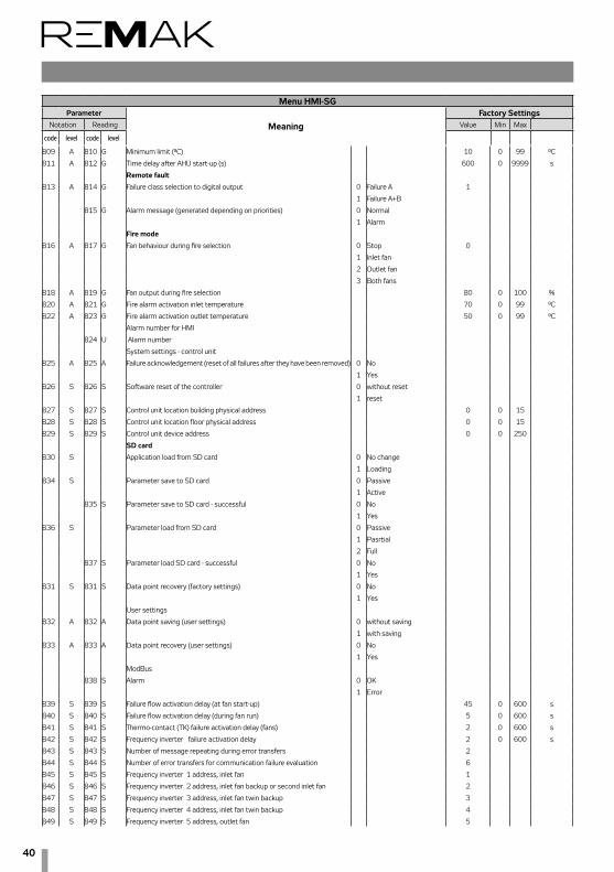
40
Menu HMI-SGParameter
MeaningFactory Settings
Notation Reading Value Min Max
code level code level
809 A 810 G Minimum limit (°C) 10 0 99 °C
811 A 812 G Time delay after AHU start-up (s) 600 0 9999 s
Remote fault
813 A 814 G Failure class selection to digital output 0 Failure A 1
1 Failure A+B
815 G Alarm message (generated depending on priorities) 0 Normal
1 Alarm
Fire mode
816 A 817 G Fan behaviour during fire selection 0 Stop 0
1 Inlet fan
2 Outlet fan
3 Both fans
818 A 819 G Fan output during fire selection 80 0 100 %
820 A 821 G Fire alarm activation inlet temperature 70 0 99 °C
822 A 823 G Fire alarm activation outlet temperature 50 0 99 °C
Alarm number for HMI
824 U Alarm number
System settings - control unit
825 A 825 A Failure acknowledgement (reset of all failures after they have been removed) 0 No
1 Yes
826 S 826 S Software reset of the controller 0 without reset
1 reset
827 S 827 S Control unit location building physical address 0 0 15
828 S 828 S Control unit location floor physical address 0 0 15
829 S 829 S Control unit device address 0 0 250
SD card830 S Application load from SD card 0 No change
1 Loading
834 S Parameter save to SD card 0 Passive
1 Active
835 S Parameter save to SD card - successful 0 No
1 Yes
836 S Parameter load from SD card 0 Passive
1 Pasrtial
2 Full
837 S Parameter load SD card - successful 0 No
1 Yes
831 S 831 S Data point recovery (factory settings) 0 No
1 Yes
User settings
832 A 832 A Data point saving (user settings) 0 without saving
1 with saving
833 A 833 A Data point recovery (user settings) 0 No
1 Yes
ModBus
838 S Alarm 0 OK
1 Error
839 S 839 S Failure flow activation delay (at fan start-up) 45 0 600 s
840 S 840 S Failure flow activation delay (during fan run) 5 0 600 s
841 S 841 S Thermo-contact (TK) failure activation delay (fans) 2 0 600 s
842 S 842 S Frequency inverter failure activation delay 2 0 600 s
843 S 843 S Number of message repeating during error transfers 2
844 S 844 S Number of error transfers for communication failure evaluation 6
845 S 845 S Frequency inverter 1 address, inlet fan 1
846 S 846 S Frequency inverter 2 address, inlet fan backup or second inlet fan 2
847 S 847 S Frequency inverter 3 address, inlet fan twin backup 3
848 S 848 S Frequency inverter 4 address, inlet fan twin backup 4
849 S 849 S Frequency inverter 5 address, outlet fan 5

41
Control units VCS
Menu HMI-SGParameter
MeaningFactory Settings
Notation Reading Value Min Max
code level code level
850 S 850 S Frequency inverter 6 address, outlet fan backup or second outlet fan 6
851 S 851 S Frequency inverter 7 address, outlet fan twin backup 7
852 S 852 S Frequency inverter 8 address, outlet fan twin backup 8
853 S 853 S Frequency inverter 9 address, 3rd auxiliary fan 9
854 S 854 S Frequency inverter 10 address, second 3rd auxiliary fan 10
857 S 857 S Frequency inverter 11 address, rotary heat exchanger 11
858 S 858 S Control unit Modbus resistance terminal 0 inactive
1 activeNetwork connection configuration (After setting – the reset is required !!)
859 A DHCP 0 passive
1 active
860 A Settings IP[w] 192 0 255
861 A Settings IP[x] 168 0 255
862 A Settings IP[y] 1 0 255
862 A Settings IP[z] 199 0 255
864 U Actual IP[w]
865 U Actual IP[x]
866 U Actual IP[y]
867 U Actual IP[z]
868 A Settings mask [w] 255 0 255
869 A Settings mask [x] 255 0 255
870 A Settings mask [y] 255 0 255
871 A Settings mask [z] 0 0 255
872 U Actual mask [w]
873 U Actual mask [x]
874 U Actual mask [y]
875 U Actual mask [z]
876 A Settings gateway [w] 0 0 255
877 A Settings gateway[x] 0 0 255
878 A Settings gateway [y] 0 0 255
879 A Settings gateway [z] 0 0 255
880 U Actual gateway [w]
881 U Actual gateway [x]
882 U Actual gateway [y]
883 U Actual gateway [z]
System settings - room unit
884 S 884 S Transition to time program delay 1 0 23 h
885 A 885 A Byte address, Diagnostic mode – byte address 5
886 A 886 A Alarm mode 0 N/A 2
1 only after alarm
2 constantly
887 S 887 S Room temperature display, combined or inlet temperature 0 Temp. from HMI-SG 0
1 Temperature average
2 Outlet Temperature
895 U 895 U Temperature unit display settings °C/°F 0 °C 0
1 °F
896 A 896 A Required value compensation setting +/- 3 0 12 °C
897 A 897 A Required value increment 0 Increment per 0.1 0 °C
1 Increment per 0.5 °C
898 A 898 A Displayed time format - 12h/24h 0 24 h
1 12 h
Passwords899 S 899 S Password for Service level access 0 9999
901 A 901 A Password for Admin level access 0 9999
902 U 902 U Password for User level access 0 9999

42
903 G 903 G Password for Guest level access 0 9999
Comunication with Building management system (BMS) - (After settings - reset required !!)LON
921 S 921 S Send heart beat (s) 2700 0 9999 s
922 S 922 S Receive heart beat (s) 3600 0 9999 s
923 S 923 S Min send intervall (s) 5 0 9999 s
924 S 924 S Service pin 0 inactive
1 active
925 S 925 S Out temperature value 0 of application 0
1 of communication
926 S 926 S Fire alarm (external) 0 of application 0
1 of communication
Modbus RTU - Slave (BMS)
925 S 925 S Out temperature value 0 of application
1 of communication
926 S 926 S Fire alarm (external) 0 of application
1 of communication
931 S 931 S Modbud Slave1 0 inactive
1 active
932 S 932 S Address Slave1 1
933 S 933 S Baud rate Slave1 default 9600 b/s
2400 (factor 10)
4800 (factor 10)
9600 (factor 10)
19200 (factor 10)
38400 (factor 10)
934 S 934 S Stop bits Slave1 0 One stop bit 1
1 Two stop bits
935 S 935 S Parity Slave1 0 Even 2
1 Odd
2 None
936 S 936 S Termination (resistor) Slave1 0 inactive 0
1 active
937 S 937 S Response timeout Slave1 5 0 3600 s
Menu HMI-SGParameter
MeaningFactory Settings
Notation Reading Value Min Max
code level code level

43
Control units VCSList of Failures (HMI-SG controller)
Failure Description Cl
ass
Failu
re
Num
ber
Failure Causes
Reduced humidifi-cation output B 10 Reduced humidification output due to the temperature priority (swimming-pool unit)
– an information message.
Auxiliary Fan B 15
1.) Communication error between control unit and the auxiliary fan frequency inverter (Modbus data bus) – inverter internal error; wrong settings of the frequency inverter data points – bus communication protocol, data transfer rate, parity, number of stop-bits, com-munication timeout; poor connection of the bus cable to the frequency inverter terminals; bus terminal resistance settings on the last frequency inverter has not been performed.
2.) Auxiliary fan failure (Modbus data bus) - thermo-contact, flow sensor
Auxiliary Fan - twin B 16
1.) Communication error between control unit and the auxiliary fan twin frequency inverter (Modbus data bus) – inverter internal error; wrong settings of the frequency inverter data points - bus communication protocol, data transfer rate, parity, number of stop-bits, com-munication timeout; poor connection of the bus cable to the frequency inverter terminals; bus terminal resistance settings on the last frequency inverter has not been performed.
2.) Auxiliary fan twin failure (Modbus data bus) - thermo-contact, flow sensor
Backup fans in the inlet B 18
Main inlet fan failure (backup fan activated) - thermo-contact, flow sensor
A Class failure – inlet backup fan shutdown
Backup fans in the outlet B 19
Main outlet fan failure (backup fan activated) - thermo-contact, flow sensor
A Class failure - outlet backup fan shutdown
Communica-tion, Modbus B 23
Communication error between control unit and the fan or ROV frequency inverter (Modbus data bus) - inverter internal error; wrong settings of the frequency inverter data points – bus communication protocol, data transfer rate, parity, number of stop-bits, commu-nication timeout; poor connection of the bus cable to the frequency inverter terminals; bus terminal resistance settings on the last frequency inverter has not been performed.
Process com-munication KNX B 23 Communication error between control unit and HMI-SG controller (KNX bus)
Room unit 1 - Temperature B 24 Disconnected or damaged HMI-SG1 controller
Room unit 2 - Temperature B 24 1) Disconnected or damaged HMI-SG2 controller
2) Wrong HMI-SG2 controller communication address setting (the same address with the HMI-SG1 controller)
Outdoor tem-perature B 25 Disconnected or damaged outdoor temperature sensor
Room temperature B 26 Disconnected or damaged room temperature sensor
Outlet tem-perature B 28 Disconnected or damaged outlet temperature sensor
Inlet temperature difference B 32
Information message on the difference between inlet and required temperatures, provid-ing the Inlet and Required Temperature Difference Monitoring has been activated (in the data point 201). If the temperature difference is higher than pre-set Maximum Difference (data point 801) or if the inlet temperature drops below the pre-set minimum threshold (data point 803), an information message is displayed.
Room tempera-ture difference B 33
Information message on the difference between room/outlet and required temperatures, providing the Inlet and Required Temperature Difference Monitoring has been activated (in the data point 201). If the temperature difference is higher than pre-set Maximum Difference (data point 807) or if the room/outlet temperature drops below the pre-set minimum threshold (data point 809), an information message is displayed.

44
List of Failures (HMI-SG controller) (continuation)
Failure Description Fa
ilure
Cl
ass
Failu
re
Num
ber
Failure Causes
Outdoor temperature dependent heat pump blocking
B 35 Information message – The heat pump blocked due to outdoor temperature
Heat pump B 36 Heat pump failure – contact
Humidification B 37 Humidifier failure - contact
Filters B 39 Filter failure - contact
Fan operat-ing hours B 40 The pre-set fan operating hours have been exceeded; operating hours are set using the
HMI-DM, TM or HMI@Web controllers.
Cooling B 41 Cooling failure (direct expansion evaporation, inverter condensing unit) -contact
ZZT (antifreeze protection)
B 42
1.) Lost communication between control unit and ROV frequency inverter - inverter internal error; wrong settings of the frequency inverter data points (bus communication protocol, data transfer rate, parity, number of stop-bits, communication timeout; poor connection of the bus cable to the frequency inverter terminals; bus terminal resistance on the last frequency inverter has not been performed)
2.) Antifreeze protection ROV/DEV has been activated due to drop in temperature below the pre-set value (data point 516).
Inlet air rela-tive humidity B 46
1.) Inlet air humidity sensor disconnected or damaged
2.) Humidity > 100%
Outdoor air rela-tive humidity B 47
1.) Outdoor air humidity sensor disconnected or damaged
2.) Humidity > 100%
Room air rela-tive humidity B 48
1.) Room air humidity sensor disconnected or damaged
2.) Humidity > 100%
Air quality (CO, CO2) B 49
1.) Air quality sensor disconnected or damaged
2.) Air quality > 3000 ppm
Back draught protection (TH) B 55 Back draught protection for the chamber after cooling – thermostat TH 167 or ES3M-T3.
Flue-gas high temperature, heater shut down
B 56 Flue-gas temperature sensor disconnected or damaged
Flue-gas high temperature, VZT shut down
A 571.) Flue-gas temperature sensor disconnected or damaged
2.) Flue-gas temperature is higher than the pre-set temperature (data point 472).
Burner failure A 58 Burner internal failure - contact
Electric preheater A 59 Temperature behind the electric pre-heater < -50°C
B 591.) Temperature sensor behind the electric heater disconnected or damaged
2.) Electric pre-heater failure - thermostat
Temperature in the inlet A 60
1.) Inlet air sensor disconnected or damaged
2.) Inlet air temperature is higher than the pre-set temperature (data point 442) – water heating antifreeze protection (PMO) is active.
Heat exchanger freezing B 61 Temperature sensor behind ROV disconnected or damaged
Electric heating A 62 Electric heater failure - thermostat
Electric reheating A 63 Electric after-heater failure - thermostat

45
Control units VCS
Water heater pump A 65 Water heater pump failure - contact
Water heating ad-ditional antifreeze protection (PMO)
A 65 Electric heating additional PMO - thermostat
Inlet fan A 66 Backup inlet fan error - thermo-contact
Inlet fan (air-flow failure) A 66
1.) Backup inlet fan error - flow sensor
2.) Single-speed fan error - flow sensor
Outlet fan A 67 Backup outlet fan error - thermo-contact
Outlet fan (air-flow failure) A 67 Backup outlet fan error - flow sensor
Air flow sen-sor (pressure) - inlet fan
A 69 Unconnected or damaged air flow sensor (pressure) - inlet fan
Air flow sen-sor (pressure) - outlet fan
A 70 Unconnected or damaged air flow sensor (pressure) - outlet fan
Fan (inlet, outlet) A 71
1.) Communication error between control unit and the inlet/outlet fan frequency inverter (Modbus data bus) - inverter internal error; wrong settings of the frequency inverter data points – bus communication protocol, data transfer rate, parity, number of stop-bits, com-munication timeout; poor connection of the bus cable to the frequency inverter terminals; bus terminal resistance settings on the last frequency inverter has not been performed.
2.) Inlet/outlet fan error - thermo-contact
Fan (inlet, outlet) – flow failure A 72
1.) Lost communication between control unit and fan frequency inverter - inverter internal error; wrong settings of the frequency inverter data points - bus communication protocol, data transfer rate, parity, number of stop-bits, communication timeout; poor connection of the bus cable to the frequency inverter terminals; bus resistance terminal settings on the last frequency inverter has not been performed.
2.) Inlet/outlet fan error - flow sensor
Water pre-heating A 741.) Temperature sensor disconnected or damaged
2.) Water temperature in the water heat exchanger return pipe > 140 °C, or water tem-perature in the water heat exchanger return pipe < 5 °C
Outlet tempera-ture-dependent fire alarm activation
A 81 Fire alarm triggered due to exceeded pre-set outlet air temperature (data point 820)
Inlet temperature-d e p e n d e n t f i re alarm activation
A 81 Fire alarm triggered due to exceeded pre-set inlet air temperature is (data point 821)
Fire alarm (external failure) A 81
1.) Fire alarm triggered by the fire dampers - contact
2.) External failure - contact
Water heater re-turn water A 82
1.) Temperature sensor disconnected or damaged
2.) Water temperature in the water heat exchanger return pipe > 140 °C, or water tem-perature in the water heat exchanger return pipe < 8 °C
List of Failures (HMI-SG controller) (continuation)
Failure Description Cl
ass
Failu
re
Num
ber
Failure Causes

46
Control (HMI-DM,HMI-TM controllers)HMI-DM (HMI-TM) control devices ensure communication between the VCS control unit and the user. They are intended for air-handling device control, handling and service. The HMI control device can be connected to the POL4xx or POL6xx controllers. During controller operation, a single HMI control device can be connected or disconnected and alternatively (in sequence) used to control multiple control units (controllers).
ConnectionThe HMI-DM controller can be connected using a serial inter-face (4-wire, twisted pair) with two RJ45 connectors. The cable length is 1.5 m (the cable is included in the delivery). When installed on a wall, the HMI-DM controller can be con-nected using a shielded 8-wire UTP cable with two RJ45 connectors. The maximum distance is up to 50 m. The HMI-TM controller can be connected to the control unit using a 4-wire cable (twisted pair) with one RJ45 connector and one slim connector. The cable length is 2.5 m (the cable is included in the delivery).
WarningAfter connecting the controller to the control unit, it is nec-essary to route the cable through the PG16 grommet. Thus degree of protection IP20 is ensured. If a higher level of protec-
tion of the distribution board cas-ing is required, the grommet will have to be resealed. An optional grommet with an RJ 45 connector can be used to make it easy to con-nect (disconnect) the HMI control-ler (an extra order is required, not included in the standard delivery). Then the RJ45 connector must be connected to the RJ45 socket on the controller. For the socket marking, see the figure.
Button (Name)
Activity Description
Scrolling knob
Turning- Selection from the menu- Selection from the param-eters or change to a value
Press - Selection/confirmation
Hold
- When logged in, press and hold for at least 3 s to go to the log-in/log-out page.- When not logged in at any access level, the log-in page is displayed.
Esc
Press - Cancels the change to the parameter value-Returns to the upper level of the menu/previous page- Returns to the last active page before accessing the Pass-word Administration page - Returns to the last active page before accessing the Home page using the Info button.
Hold - Goes to the Start Menu
Info
Press - Goes to the Main Menu from the current menu page - Goes to the Start Menu page from the Main Menu
Flashing green
- Air-handling unit start-up sequence
Green light - Air-handling unit operation
Failures
Press - Every time you press this button, you will cycle through the following pages → List of Failures → His-tory of Failures → Alarm Settings (failure confirmation and reset)
Flashing red
- Active unconfirmed failures
Red light - Active confirmed failures
Figure 1
Figure 2 – HMI-DM cotroller
Table 1 – Function Buttons
HMI-DM controller
Operating conditionsDegree of protection: IP 31. Permissible ambient temperature: -40 °C to 70 °C. Relative humidity <95 %.
Device DescriptionThe controller consists of two separate parts – the face plate with a display and the rear plate. Dimensions of the HMI-DM controller are 144x96x26 mm and the integrated LCD display resolution is 208x96 pixels. The display can show 8 lines. The HMI-DM controller is equipped with three function buttons, INFO, FAILURE and ESC, and one scrolling knob. The scrolling knob and buttons are used to navigate within the menu and to change the parameters and control values. The INFO, FAILURE and ESC buttons are equipped with LEDs to indicate operating states. The controller can also be delivered in a version for free loca-tion. The magnets on the rear side of the HMI enable the con-troller to be attached to metal parts (e.g. the air-handling unit).
Info
Failure
ESC Scrolling knob
For fixed mounting, the controller is equipped with threaded holes on its rear side to screw it to the mounting plate.

47
Control units VCSControl (HMI-DM,HMI-TM controllers)
HMI-TM controller
Operating conditionsDegree of protection: IP 65 (version with magnetic fixation). Permissible ambient temperature: -20 °C to 60 °C. Relative humidity: 5 % to 95 %.
Device DescriptionDimensions of the HMI-TM controller are 173x95.5x21.6 mm. The LCD display resolution is 128x96 pixels. The HMI-TM con-troller is equipped with 6 function buttons, INFO, FAILURE, ESC, UP, DOWN and ENTER. The INFO, FAILURE and ESC buttons simultaneously indicate operating states (Stop – fail-ure, operation). The UP, DOWN and ENTER buttons are used to navigate through the menu. The magnetic plate on the rear side of the HMI enables free attachment to metal objects.
Figure 3 – Installation on a Wall
Figure 4 – HMI-TM controller
Table 2 – Function ButtonsButton (Name)
Activity Description
Up
Press - Scrolling the list upwards - Increases the parameter value
Hold
- Hold this button longer than 1.5 s to speed up the list scrolling upwards- Increases the parameter values in higher grades
Down
Press - Scrolling the list downwards - Decreases the parameter values
Hold
- Hold this button longer than 1.5 s to speed up the list scrolling downwards - Decreases the parameter values in higher grades
Enter
Press Selection/confirmation
Hold
- When logged in, press and hold for at least 3 s to go to the log-in/log-out page. - When not logged in at any access level, the log-in page is displayed.
Info
Press
- Goes to the Main Menu from the current menu page- Goes to the Start Menu page from the Main Menu
Flashing green
- Air-handling unit start-up sequence
Green light - Air-handling unit operation
Failures
Press
- Every time you press this button, you will cycle through the following pages → List of Failures → His-tory of Failures → Alarm Settings (failure confirmation and reset)
Flashing red - Active unconfirmed failures
Red light - Active confirmed failures
EscPress
- Cancels the change to the parameter value- Returns to the upper level of the menu/previous page- Returns to the last active page before accessing the Pass-word Administration page - Returns to the last active page before accessing the Home page using the Info button.
Hold - Moves to the HMI Settings page
Info
Failure
ESC
Up
Down
Enter

48
Control (HMI-DM,HMI-TM controllers)
a The user log-in is graphically indicated by the key symbol in the page heading. The access levels are distinguished by the following symbols.
b Page Headingc Current line from the total number of lines on the paged The page also includes the line above the current displaye The page also includes the line below the current displayf Access to the Main Menu from the current menu pageg Current line of the selection
Access to the Submenu The cursor marks the selection of parameters on a correspond-ing line. The arrow indicator in the right part of the display indicates the option to access a submenu.n Turn the knob (or use the Up and Down buttons) to select the required line. n Press the knob (Enter) to access the submenu.
If only the value description is highlighted on the line, the value on the line is intended only to be displayed, refer to Temperatures.
Value Settings If the description and value of the parameter is highlighted on the line, the highlighted value can be changed. n Turn the knob (or use the Up and Down buttons) to select the line.n Press the knob (Enter) to confirm the page selection.n Turn the knob (or use the Up and Down buttons) to change the parameter values.n Press the knob (Enter) to confirm the value change.n Press the Esc button to exit the page.
Setting the Selection from Multiple Parametersn The current parameter selection is marked. n Turn the knob (or use the Up and Down buttons) to select a new parameter.n Press the knob (Enter) to confirm the selection or press the Esc button to retain the original value as valid.
Setting the Continuous Value using the KnobThe scale displays minimum and maximum values. n Set the arrow on the respective numbern By turning the wheel, the number can be changed from 0 to 9.n The cursor is moved to the following item automaticallyn Press the knob to confirm the selection or press the Esc button to retain the original value as valid
Setting the Continuous Value using the Up and Down Buttonsn Press (hold) the Up or Down button to set the required value.n Press Enter to confirm the selection or press the Esc but-ton to retain the original value as valid.
Display Layout
User Icon
GUEST
USER
ADMINISTRATOR
SERVICE
Table 3 – access levels
Figure 5 – LCD isplay
ab
d
c
e
g f

49
Control units VCSControl (HMI@Web – Connection to PC and LAN/WAN)
Installation and Connection to PC and LAN/WAN
Basic RequirementsThe HMI@Web controller is intended to operate the VCS control unit using an internet browser. This controller is a more convenient variant of HMI DM, TM controllers featuring remote control and PC control. However, it is not equipped with comfort features like data collection and filing, e-mail messages on system failure events. User access is the same as with HMI DM, TM controllers. No administration of users or their roles is created.The PC must be equipped with an Ethernet network card with the RJ-45 connector, or connected to the LAN network - the HMI@Web system can be connected directly to (one) PC or integrated into the LAN, resp. WAN network, and is acces-sible from any computer (access authorization is needed) in the network. The TCP/IP protocol must be installed on your PC (to install the TCP/IP protocol, refer to your operating system manual).
Figure 1 – Network connection settings
WarningBefore putting the HMI@Web controller operated by PC, respectively via LAN network, into operation, the installation of the controlled air-handling unit must be checked to see whether it has been performed in accordance with its Instal-lation and Operating Instructions (installation, inspections, safety precautions, heating media, etc.)! Refer to "Location and Installation".
Default HMI@Web IP Address Setting During production, the HMI@Web unit was assigned the fixed IP address: 192.168.1.199, mask 255.255.255.0, and the default port 0.0.0.0.
NoticeIf this address cannot be used in LAN, it is necessary to change the setting from the computer (directly connected PC as described below) before connecting it to the network.
HMI@Web controller Start-up Procedure
1. Step: HMI@Web controller connection:
* This cable is not part of delivery.
Notice – Proxy server settingso ensure proper interoperation of the internet browser on your PC directly connected to the HMI@Web unit, it is necessary to disable proxy server! In Internet Explorer 8: Go to "Tools" / "Internet Options" >> "Connections" >> button / "Local network options" / "Specify" … lower half of the window = "Proxy server" box – must not be checked (see figure).
Figure 6 – HMI@Web unit connected directly to PC
HMI@Web
HMI@Web + stand-alone PC = HMI@Web controller connected directly to PCUsing the Ethernet crossed cable* (UTP cable, RJ-45 connec-tors) connect the HMI@Web unit ("LAN" socket on the upper side of the controller) to the network card of your computer.
Figure 7 Attention: Connector RJ-45 marked BSP, BUS cannot be used! It is intended for HMI controller – refer to "HMI Con-troller Operating Instructions".Max. length of the cable be-tween the HMI@Web and com-puter can be 100 m; however, we recommend 80 m. Switch
the HMI@Web main switch on. If a greater distance between the PC and the VCS control unit controlled by the HMI@Web controller is desired, it will be necessary to use a structured network (Ethernet) including active network elements – see below, or contact a specialized PC and IT supplier.

50
Control (HMI@Web – Connection to PC and LAN/WAN)Connection of the VCS control unit with the HMI@Web controller to the LAN
Warning If the default IP address of the HMI@Web unit cannot be used in the LAN network – i.e. a different address range is used in the LAN network (e.g. 10.0.0…, 192.168.10…..), or the existing PC within the LAN network has already been assigned the IP address …199 (can be verified by the "ping + IP address" com-mand) which must be retained - it is necessary to change the HMI@Web IP address setting from the computer (as described above) before connecting it to the network.If you are not an administrator of the LAN network, you will have to contact your LAN administrator. The same applies if you are not an administrator of your computer.Using the Ethernet cable (not included in the HMI@Web delivery) connect the HMI@Web unit to the LAN network connecting point in the same way as any other LAN device. The same conditions as in step 1 (connecting points, cable lengths) apply for connection to LAN. To set the addresses, it is possible to use other controllers like HMI SG, TM and DM. Maximum HMI@Web unit distance from an active network element must comply with the Ethernet network conditions.
Notice: The HMI@Web unit can also be connected to the LAN network via the wi-fi access point in the client mode, etc. – consult your network administrator.
Figure 8 – HMI@Web connected to local network
HMI@Web
HMI@Web
To be able to operate the HMI@Web unit, a unique IP address within the network range (see fig. # 8) must be assigned to the HMI@Web unit. Go to "Connection" >> "LAN connection" (refer to Step 4: Activation).Always restart the HMI@Web unit after assigning a new IP address – the new setting is applied after restart.Attention! Always consult your network administrator if con-necting the HMI@Web to LAN.
2. Step: Computer Configuration - TCP/IP Settings
WarningIn this step, settings of the PC using Microsoft Windows® XP are described; if you use other operating systems you will have to perform corresponding settings of your computer in accordance with your operating system user manual, or ask an expert for help. This setting procedure is needed only for a permanent direct connection to PC, or to change the HMI@Web settings before its integration into the LAN network.
After setting the HMI@Web unit (following the below de-scribed procedure), and when the HMI@Web default address complies with network addressing, it is only necessary to en-able new hardware in the infrastructure administration – there is no need to make any other adjustments to individual PCs.
Adjust PC network card settings in Windows:Go to "Start" >> "Settings" >> "Control Panel" >> "Network connection"). Click (right mouse button) on "Local network connection", then on "Properties", and display "Internet pro-tocol (TCP/IP)" properties“.
Figure 9 – TCP/IP settings
If the protocol is not found in the list of items (it is not installed), add the item to the system. Click the "Install" button, select the "Internet protocol (TCP/IP)", and follow the instructions on the screen.Select item "Use the following IP address". Type "192.168.1.3"** into the "IP address" box and "255.255.255.0" into the "Net-work mask" box. Do not type anything into the item boxes of the second part of the window (leave them blank). If you are prompted by the system to restart, confirm the restart immediately.
Connection, resp. TCP/IP Protocol VerificationTo verify the settings and connection, type the HMI@Web address into the URL box of the internet browser (the HMI@Web system must be switched on); it should start functioning in 0.5 – 3 minutes - the time needed to initialize the webserver.
After sending the request, and if the settings and connecting are correct, the HMI@Web unit is ready to be configured, and the login window is displayed on the screen requesting the user name and password.
Figure 10 – IP address entry
** Any number from 1 to 254 except 199 (which is assigned to the HMI@Web controller) can be used in the first place of the IP address.
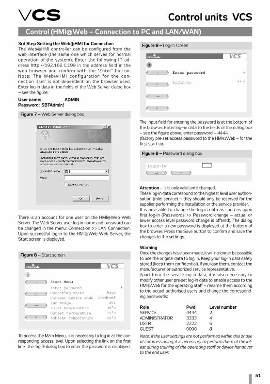
51
Control units VCSControl (HMI@Web – Connection to PC and LAN/WAN)
3rd Step Setting the Web@HMI for ConnectionThe Web@HMI controller can be configured from the web interface (the same one which serves for normal operation of the system). Enter the following IP ad-dress http://192.168.1.199 in the address field in the web browser and confirm with the "Enter" button. Note: The Web@HMI conf igurat ion for the con-nection itself is not dependent on the browser used. Enter log-in data in the fields of the Web Server dialog box – see the figure:
User name: ADMINPassword: SBTAdmin!
Figure 7 – Web Server dialog box
Figure 8 – Start screen
Figure 9 – Log-in screen
Figure 8 – Password dialog box
There is an account for one user on the HMI@Web Web Server. The Web Server user log-in name and password can be changed in the menu: Connection >> LAN Connection. Upon successful log-in to the HMI@Web Web Server, the Start screen is displayed.
To access the Main Menu, it is necessary to log in at the cor-responding access level. Upon selecting the link on the first line the log-in dialog box to enter the password is displayed.
The input field for entering the password is at the bottom of the browser. Enter log–in data to the fields of the dialog box – see the figure above; enter password – 4444.(factory pre-set access password to the HMI@Web – for the first start-up.
Attention – it is only valid until changed.These log-in data correspond to the highest level user authori-sation (role: service) – they should only be reserved for the supplier performing the installation or the service provider.It is advisable to change the log-in data as soon as upon first log-in (Passwords >> Password change – actual or lower access level password change is offered). The dialog box to enter a new password is displayed at the bottom of the browser. Press the Save button to confirm and save the changes to the settings.
WarningOnce the changes have been made, it will no longer be possible to use the original data to log in. Keep your log-in data safely stored (keep them confidential). If you lose them, contact the manufacturer or authorized service representative.Apart from the service log-in data, it is also necessary to modify other user pre-set log-in data to enable access to the HMI@Web for the operating staff – rename them according to the actual authorised users and change the correspond-ing passwords:
Role Pwd Level numberSERVICE 4444 2ADMINISTRATOR 3333 4USER 2222 6GUEST 0000 8
Note: If the user settings are not performed within this phase of commissioning, it is necessary to perform them at the lat-est during training of the operating staff or device handover to the end user.
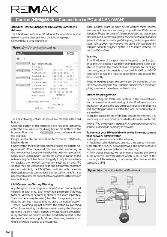
52
Control (HMI@Web – Connection to PC and LAN/WAN)
Figure 10 – LAN connection settings
4th Step: How to Change the HMI@Web Controller IP AddressThe HMI@Web controller IP address for operation in your network can be changed from the following page:Connection >> LAN connection
The lines allowing entries of values are marked with a red button. Once the button of the respective line has been activated, enter the new value in the dialog box at the bottom of the browser. Press the button to confirm and save the changes.Progressively enter and save all the items "Enter …" (Address, Mask or Gate).Finally, restart the HMI@Web controller using the option "Ap-ply + Reset". After the restart, the device starts reporting on the new address (once the initiation has been completed – it takes about 3 minutes).** To resume communication (if the network segment has been changed), it may be necessary to readjust the network connection settings on your PC so that they are compatible with the HMI@Web controller (respectively LAN); the HMI@Web controller with the modi-fied setting can be alternatively connected to the LAN. It is necessary to enter the correct network address in the browser to enable log-in.
LAN Connection Setting Warning Any changes to the settings must be performed cautiously and carefully at each step. Each modifiable parameter (Address, Mask or Gate) must be carefully checked and saved separately. Then it is necessary to send (plan) the change entry – after that, the settings must be finished using the option "Apply + +Reset". (Warning: Do not perform the restart by switching off or disconnecting the device – when saving the changes using the "Apply + Reset" option, the settings are simultane-ously stored in an archive which is needed for restart of the device after a power supply failure - otherwise, there is a risk of uncontrolled changes to the settings.)
Note: Control start-up after device restart takes several seconds – it does not to do anything with the Web Server initiation. That is because of the standard start-up sequences that are being performed during the connected air-handling system start-up, i.e. opening of dampers, pre-heating and fan start. We strongly recommend not using the configuration with the address assigned by the DHCP server; instead, use the fixed IP address.
WarningIf the IP address of the given device happens to get lost (e.g. once the LAN setting have been changed) and it is not pos-sible to establish the connection (no response to the "ping" command, etc.), it is possible to use the HMI-DM or HMI-TM controllers to set the required parameters and restart the device directly.
Note: In extreme cases, the device can be looked up within the network using the MAC address (indicated on the name plate) – contact the network administrator.
Internet IntegrationBy connecting the WebClima system to the local network via the above-mentioned setting of the IP address and au-thorization of users, the basic (direct-interactive) monitoring and operating possibilities within the local network or by PC are enabled. To enable access to the WebClima system via internet, it is necessary to ensure direct access to the device from internet.
Notice: This is necessary especially if supervision (operation, service) outside the company is required.
To connect your HMI@Web unit to the internet, contact your network administrator.In doing so, we recommend the following:nImplement the HMI@Web unit into the secured inner net-work after the router / network firewall. The direct access to the unit must be ensured by further directing. nTo increase security, we recommend locating the device in the reserved network (DMZ) which is not a part of the company's LAN network, or accessing the device via the company's VPN.
Figure 14 – connection to the WAN network
HMI@Web
WAN
HMI@Web

53
Control units VCSControl (HMI@Web – Connection to PC and LAN/WAN)
The network administrator in this case has at their disposal 2 public static IP addresses for the HMI@Web control unit: 88.100.1.1 and 88.100.1.2The administrator can set the IP address translation at the router, for example, as follows:
Public IP address Inner IP address88.100.1.1 192.168.1.488.100.1.2 192.168.1.5
or (to minimize the need for public addresses) leading through only one public IP address and communication port.
Warning to the network administratorTo enable access via internet it is necessary to enable access to the inner IP address via port 80 (http).Other communication ports must be DISABLED to keep the operation secure!
REMAK does not bear any responsibility for any misuse of the HMI@Web software (Windows CE) or unauthor-ized penetration of the inner LAN network due to insuf-ficient inner network security.
Internet Browser Settings to operate the HMI@Web controllerSupport of JavaScript and cookies must be enabled to ensure correct functioning of the browser interface on each PC connected to the HMI@Web controller. JavaScript is used to update values in the right (information) panel and for programming time schedules, and cookies are used for login. Further, file opening in new windows must also be enabled.As the parameters are measured on-line, we also recommend adjusting the temporary files retention (cache settings) in the internet browser (this is essential especially for MS Internet Explorer). The browser must verify the actual page version in every access to the page. Otherwise, saved not current values of parameters can be presented. If you have any doubts whether the read data are correct, refresh the page by clicking on the refresh icon on the browser menu bar, or use shortcut keys CTRL+F5 – forced page loading outside cache. The HMI@Web graphic user interface is optimized for Micro-soft Internet Explorer 6.0/7.0 and FireFox 2.0.Other web browsers' settings must be checked in accordance with the following instructions.
Internet Explorer 8.0 and above
Internet Explorer JavaScript Support:Go to the Internet Explorer menu "Tools" / "Internet Options" >> "Security" >> "Custom Level" >> "Scripting" – must be enabled.
Figure15 – JavaScript support settings
Setting the Network Elements to enable HMI@Web Access via InternetAsk your local network administrator to perform these activities!

54
Control (HMI@Web – Connection to PC and LAN/WAN)Internet Settings (Explorer Cookies):Go to the Internet Explorer menu "Tools" / "Internet Options" >> "Privacy" >> "Advanced" >> "Accept Cookies"(see fig. # 16)
Figure 16 – Cookies settings (IE)
Temporary Files' SettingsGo to the Internet Explorer menu "Tools" / "Internet Options" >>, "General >> "Temporary Internet files" >> "Settings...".
Figure 17 – Temporary Files' Settings (IE)
In the following window "Setting" >> "Check fro newer ver-sions of stored files >> select "Every visit to the page" >> set "Amount of disk space to use:" to the minimum (8 MB). Then save the settings clicking the "OK" button.
Figure 18 – Temporary Files' Settings (IE)
Mozilla Firefox
Mozilla Firefox JavaScript supportGo to menu "Tools" / "Options" >> bookmark "Contents" >> Enable JavaScript should be checked.
Note: The control setting with Mozilla Firefox is the same as with Microsoft Windows and Linux systems.
Figure 19 – JavaScript support settings (Firefox)
Mozilla Firefox Cookies SettingsGo to menu "Tools" / "Options" >> bookmark "Private" >> menu Cookies >> cookies should not be blocked, if so, enable servers to set cookies.
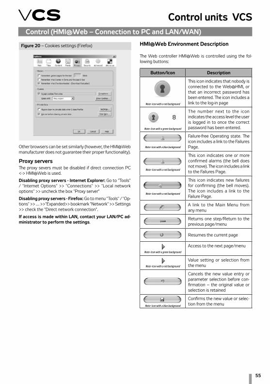
55
Control units VCSControl (HMI@Web – Connection to PC and LAN/WAN)
HMI@Web Environment Description
The Web controller HMI@Web is controlled using the fol-lowing buttons:
Button/Icon Description
This icon indicates that nobody is connected to the Web@HMI, or that an incorrect password has been entered. The icon includes a link to the log-in page
The number next to the icon indicates the access level the user is logged in to once the correct password has been entered.
Failure-free Operating state. The icon includes a link to the Failures Page.
This icon indicates one or more confirmed alarms (the bell does not move). The icon includes a link to the Failures Page.
This icon indicates new failures for confirming (the bell moves). The icon includes a link to the Failure Page.
A link to the Main Menu from any menu
Returns one step/Return to the previous page/menu
Resumes the current page
Access to the next page/menu
Value setting or selection from the menu
Cancels the new value entry or parameter selection before con-firmation – the original value or selection is retained
Confirms the new value or selec-tion from the menu
Note> Icon with a blue background
Note> Icon with a red background
Note> Icon with a red background
Note> Icon with a blue background
Note> Icon with a green background
Note> Icon with a red background
Note> Icon with a red background
Note> Icon with a green background
Figure 20 – Cookies settings (Firefox)
Other browsers can be set similarly (however, the HMI@Web manufacturer does not guarantee their proper functionality).
Proxy serversThe proxy severs must be disabled if direct connection PC <-> HMI@Web is used.
Disabling proxy servers - Internet Explorer: Go to "Tools" / "Internet Options" >> "Connections" >> "Local network options" >> uncheck the box "Proxy server"
Disabling proxy servers - Firefox: Go to menu "Tools" / "Op-tions" >> … >>"Expanded>> bookmark "Network" >> Settings >> check the "Direct network connection".
If access is made within LAN, contact your LAN/PC ad-ministrator to perform the settings.

56
Control (HMI@Web – Connection to PC and LAN/WAN)
* HMI@Web controller automatically switches between summer and winter time according to European customs.
Basic HMI@Web Operation Settings – RecapitulationThe basic HMI@Web system commissioning settings to prepare it for operating staff:n Assigning authorization groups to users and their setting before putting the unit into operation (to ensure unit security against unauthorized access).n System time setting*
Required Settings in Temperature Modes:Required temperature settings are performed from the page Settings >> Temperature Modes.
Clicking the red button at the respective temperature you will display a dialog box for a new temperature entering. Save the new temperature using the .
button. To return to the previous page in the menu, click the button. To go to the Main Menu, click the
.
Weekly (Daily) Time Schedule SettingsWeekly time schedule can be set from the page Settings >> Time Modes >> Time Schedule. An exception time schedule can also be set in the weekly
time schedule. It is possible to set maximum 6 time chan-ges and program states for each day of the week. Clicking the red button you will display a dialog box at the bottom of the browser window:
Save the new time value using the button. Each
program state will not be applied. For the detailed descrip-tion of the time schedule settings, refer to the chapter "Temperature and Time Modes".
time is assigned with a desired program state (fan speed stages and temperature mode). The program state can be entered using the dialog box displayed after clicking the red
button on the row of the respective program state:
Confirm the new program state using the button. The time assigned with *:* characters and Stop

57
Control units VCSList of Data Points (HMI-DM, HMI-TM and HMI@WEB controllers)
Monitor Monitor Current modes Current modes
ActStateEquipment Current device stateFanStageExtCnt Fan output stage (external control)FanStatus Fan stateActual time schedule Current time schedule
CalendarWeek Weekly time scheduleCalendarExcept Exception time scheduleCalendarOff Switch-off time schedule
NumbOfFailures Current number of failuresTemperatures Temperatures
Supply Inlet air temperature °CRoom Room temperature °CRoom unit 1 Temperature (HMI-SG1) °CRoom unit 2 Temperature (HMI-SG2) °CReturn air Outlet air temperature °COutdoor Outdoor air temperature °CReturn water heat Return water temperature from the water heater °CAir heat exchanger Outlet air temperature behind the heat exchanger °CAir electric preheat Temperature behind the electric pre-heater °CReturnWaterPreheating Return water temperature from the water pre-heater °CExtraElectricHeating Temperature behind the electric after-heater °CFlue gas Flue gas temperature °CValidRegulationRoom Room temperature (for control) °C
Humidity HumiditySupply air relative Inlet - relative %r.H.Supply air absolut Outlet - absolute g/kgSupply air enthalpy Inlet - enthalpy kJ/kgRoom relative Room - relative %r.H.Room absolut Room - absolute g/kgRoom enthalpy Room - enthalpy kJ/kgOuts air relative Outdoor - relative %r.H.Outs air absolut Outdoor - absolute g/kgOuts air enthalpy Outdoor - enthalpy kJ/kg
Flow (Pressures) Flow (Pressures)SupplyPress SupplyPress PaReturnPress ReturnPress PaSupplyFlow SupplyFlow m3/hReturnFlow ReturnFlow m3/h
Air quality Air quality
CO2 (VOC,CO)
CO2 (VOC, CO) ppm
Outputs PerformancesFan supply output Inlet fan output %Fan exhaust output Outlet fan output %Fan additional output Auxiliary fan output %ExtraElectricalHtgPos Outlet level for the electric reheater %Heating valve Heating mixing set valve position %Cooling valve Cooling valve position %Electrical preheating Electric pre-heater outlet position %ElectricalHeatingValve Electric reheater outlet position %Heat pump output Heat pump outlet position %Mixing section position Outlet position to the mixing damper %Heat exchanger position Heat exchanger control outlet position %Gas heating out level Outlet level for the gas heater %BypassDamperPosition Outlet position for gas heater's BP damper %Request humidity Request for humification %Request dehumidity Request for dehumidification %
Working states Operating statesFanSupplyStatus Inlet fan stateFanExhaustStatus Outlet fan stateFanAdditionalStatus Auxiliary fan stateElectPreheat Electric pre-heater stateWaterPreheat Water pre-heater pump stateElectReheating Electric re-heater statePumpOfWaterHeating Pump of water heatingStateHeatExchanger Rotary exchanger StatePrehtgFunctionsWaterHtg Pre-heating functions (water heating)WaterCoolPump Water cooler pump stateCoolingStDXCool Cooling stage (2St)CoolInverter Cooling stage (inverter)Cool1Step Cooling state (1 St + inverter)HeatPump Heat pump stateElectricHeater Electric heater stateGasHeater Gas heater stateStateHumidifier Humidifier state %
Settings Settings
Date and Time
Date and time
TimeValidity System time validityTemp modes Temperature modes
Comfort - Heating Comfortable heating 22.6 0 99 °CComfort - Cooling Comfortable cooling 24.6 0 99 °CEconomic - Heating Economy heating 20.6 0 99 °CEconomic - Cooling Economy cooling 28 0 99 °CExSpvSupplyTmp Extra required inlet air temperature 20 0 99 °C
Manual mode Manual modeTime schedules Time modes
CalendarWeek Weekly time scheduleCalendarExcept Exception time scheduleCalendarOff Switch-off time schedule
Menu HMI-DM,HMI-TM a HMI@WEB
Menu MeaningFactory settings
Value Min Max Units

58
List of Data Points (HMI-DM, HMI-TM and HMI@WEB controllers)
Menu HMI-DM,HMI-TM a HMI@WEB
Menu MeaningFactory settings
Value Min Max Units
Control humidity Humidity control
DehumSpvRel Dehumidification required relative value 60 0 100 %r.H.DehumSpvAbs Dehumidification required absolute value 12 0 100 g/kgHumMaxSpv Maximum humidity required value 80 0 100 %r.H.ActualValueHum Current humidity valueActCascSpvDeh Calculated current dehumidification required value in cascade controlHumMaxCtlr Maximum humidity %HumidityCtrl Humidification outputDeHumidityCtrl Dehumidification output %Dewpoint Dew point current value °CDewpointDedZone Dew point deviation 1 -64 64 °C
Fans FansRegulFans-Flow(Press) RegulFans-Flow(Press)
SupplyPrsRangeSnsr SupplyPrsRangeSnsrReturnPrsRangeSnsr ReturnPrsRangeSnsrSupplyFlowRangeSnsr SupplyFlowRangeSnsrReturnFlowRangeSnsr ReturnFlowRangeSnsrSupplyKFactor SupplyKFactorReturnKFactor ReturnKFactorNmbrOfSplyFans NmbrOfSplyFansNmbrOfRtrnFans NmbrOfRtrnFansEnable - K Factor Enable - K Factor
FanSupplyOutputSetpointVal Inlet fan outputFan output 1. stage % Output settings St1Fan output 2. stage % Output settings St2Fan output 3. stage % Output settings St3Fan output 4. stage % Output settings St4Fan output 5. stage % Output settings St5
FanExhaustOutputSetpointVal Outlet fan outputFan output 1. stage % Output settings St1Fan output 2. stage % Output settings St2Fan output 3. stage % Output settings St3Fan output 4. stage % Output settings St4Fan output 5. stage % Output settings St5
FanAddOutputSetpointVal Additional fan outputFan output 1. stage % Output settings St1Fan output 2. stage % Output settings St2Fan output 3. stage % Output settings St3Fan output 4. stage % Output settings St4Fan output 5. stage % Output settings St5
TRN Correct Outlet fan speed TRN correctionValueOfCorrection For all stagesFanOutputSt1 TRN correction for stage 1FanOutpuSt2 TRN correction for stage 2FanOutputSt3 TRN correction for stage 3FanOutputSt4 TRN correction for stage 4FanOutputSt5 TRN correction for stage 5
Back-up supply fan Single-speed inlet fan backupStrtUpDlyFlowMain Failure flow evaluation time-out after main fan start-up 180 0 9999 sStrtUpDlyFlowBackUp Failure flow evaluation time-out after backup fan start-up 180 0 9999 sSupplyFanBackUp Active main fan backup
Back-up exhaust fan Single-speed outlet fan backupStrtUpDlyFlowMain Failure flow evaluation time-out after main fan start-up 180 0 9999 sStrtUpDlyFlowBackUp Failure flow evaluation time-out after backup fan start-up 180 0 9999 sExhaustFanBackUp Active main fan backup
MinStOnTimeTrans Time transition to 2St speed – two-speed fans 15 0 999 sRundownTmTrans Time transition to 1St speed - two-speed fans 12 0 99 sBlckHighSpeedFan Outdoor temperature-dependent fan speed interlocking -60 -64 64 °CForceStrtTimOn1St Forced fan start-up to 1St speed (TRN – damper output absent) 20 0 99 °CDelayStartFan Fan start-up delay (after damper) 20 0 9999 sFanRunDwn Fan run-out 180 0 9999 sFlowActDelayStrtErr Failure flow activation delay (at fan start-up) 45 0 600 sFlowActDelayRunErr Failure flow activation delay (during fan run) 5 0 600 sTherContActDelayTmErr Thermo-contact (TK) failure activation delay (fans) 2 0 600 sFreqInvActSetDelayTmErr Frequency inverter failure activation delay 2 0 600 s
Control Parameters Control parametersValueOfTemperatureRegulation Temperature control values
MaxDevRmSplyTemp Maximum difference between room and inlet temperatures 5 0 64 °CMinDevRmSplyTemp Min. difference between room and inlet temperatures 5 0 64 °CActCascSpvHeating Calculated required temperature for heating with cascade control °CActCascSpvCooling Calculated required temperature for cooling with cascade control °CActMainSpvHeating Calculated required temperature for heating °CActMainSpvCooling Calculated required temperature for cooling °CActualTempControlMode Current temperature-dependent control (inlet, room, outlet)
SplyTempLimitation Inlet temperature limitationSplyMinLimit Minimum inlet air temperature 15 0 64 °CSplyMaxLimit Maximum inlet air temperature 35 0 64 °C
Sequences SequenceWaterHtgWithFunctionPreHtg Water heating with pre-heating function
PmpStrtOutTmpOutdoor temperature-dependent pump start-up in the AHU Stop and Run mode 5 -64 64 °C
PmpMinRunTime Minimum pump run time 180 0 9999 sPmpKickTm Pump downtime to the pump turning activation 168 0 9999 hPmpKickTmOn Active pump turning time 60 0 9999 sPreHtgTm Active water pre-heating operation time 120 0 600 sPreHtgTmOff Function blocking time between AHU unit shut-down and restart 5 0 30 minPreHtgEquCurX1 Water heater circuit heating curve setting at the AHU start-up X1 -10 -30 5 °CPreHtgEquCurY1 Water heater circuit heating curve setting at the AHU start-up Y1 (%) 100 0 100 %PreHtgEquCurX2 Water heater circuit heating curve setting at the AHU start-up X2 10 0 50 °CPreHtgEquCurY2 Water heater circuit heating curve setting at the AHU start-up Y2 (%) 10 0 100 %
StrtDelaySwtchAntiFreeze Stop to Run mode switching delay AP trigger value 60 0 600 sStrtAntiFreezeInRun Water heat exchanger dependent AP trigger value - AHU in Run mode 15 0 50 °C

59
Control units VCSList of Data Points (HMI-DM, HMI-TM and HMI@WEB controllers)
Menu HMI-DM,HMI-TM a HMI@WEB
Menu MeaningFactory settings
Value Min Max Units
StrtAntiFreezeInStop Water heat exchanger dependent AP trigger value - AHU in Stop mode 30 0 50 °CDlyEvalSplyAntiFreeze Inlet air dependent AP evaluation enabling delay after the unit start-up 60 0 600 sStrtSplyAntiFreezAlmA Inlet air temperature dependent AP start-up – failure alarm A 6 -64 64 °CStrtSplyAntiFreez Inlet air temperature dependent AP start-up 8 -64 64 °CMaxTempReturnWater Maximum return water temperature 70 20 120 °C
Electric heating Electric HeatingActiveElectricalHtg Electric heating switching on – request for heating 20 0 100 %HystOffElectricalHtg Electric heating hysteresis 10 1 100 %
Gas heating Gas heatingEnableSequenceCool Cooling sequence enablingMinOnTime Minimum burner run time 150 0 600 sMinOffTime Minimum burner downtime 150 0 600 sBlckTmAgainStrt1StBurner Burner restart protection time (burner Stage 1) 150 0 600 sRampModulationBurner Modulation burner opening/closing speed (%/s) (burner Stage 1) 5 0 20 %/sMinLoadOff2StBurner Heating request value for the burner Stage 2 switch-off (%) 40 10 100 %SetPointAlarmTmpFlueGas Maximum flue-gas alarm temperature 230 210 400 °CMaxTempFlueGas Maximum flue-gas temperature 210 160 230 °CSetPointTempFlueGas Requested flue-gas temperature 160 150 210 °CMinTmpFlueGas Minimum flue-gas temperature 150 150 160 °C
Electrical preheating Electric pre-heatingSetPointPreHtgTmp Required temperature for pre-heating -20 -50 10 °CBlckElPreHtgOutTmp Outdoor dependent electric pre-heating blocking -30 -50 10 °CActiveElPreHtg Heating request-dependent electric pre-heating switch-on 20 0 100 %HystOffPreHtg Hysteresis for electric pre-heater switch-off 10 0 100 %
Water preheating Water pre-heatingPreheatPumpStpt Outdoor dependent pre-heating (pump) start-up 5 -50 15 °CPmpKickTm Pump downtime to the pump turning activation 168 0 9999 hPmpKickTmOn Active pump turning time 30 0 9999 sPmpMinRunTime Minimum pump run time 30 0 9999 s
Extra electrical heating Electric reheatingActiveExtraElHeating St1 heating request dependent electric re-heating start-up 20 0 100 %HystOffExtraElHeating Hysteresis for electric re-heating switch-off 10 1 100 %MaxPowExtraHtgForFanSt1 Fan St1 dependent outlet limitation 100 0 100 %MaxPowExtraHtgForFanSt2 Fan St2 dependent outlet limitation 100 0 100 %MaxPowExtraHtgForFanSt3 Fan St3 dependent outlet limitation 100 0 100 %MaxPowExtraHtgForFanSt4 Fan St4 dependent outlet limitation 100 0 100 %MaxPowExtraHtgForFanSt5 Fan St5 dependent outlet limitation 100 0 100 %HeatPump - heating Heat pump - heatingStptBlckOutTmp Outdoor temperature dependent heat pump blocking 5 -45 35 °CStptHysOutTmp Temp. hysteresis for outdoor temperature dependent heat pump unblocking 3 1 10 °CMinRunTm Minimum operating time for heat pump heating 60 0 9999 sBlckTmAgainStrt Re-heating blocking 120 5 600 sActiveHeatPump Heat pump switching on 20 0 100 %HysOffHeatPump Digital output opening hysteresis 10 1 100 %AlarmFromOutTmp Information - outdoor temperature dependent heat pump heating blockingStartAnalogVal Heat pump analogue signal lower level 30 0 50 %
HeatPump - cooling Heat pump - coolingStptBlckOutTmp Outdoor temperature dependent heat pump blocking 14 -45 35 °CStptHysOutTmp Temp. hysteresis for outdoor temperature dependent heat pump unblocking 3 1 10 °CMinRunTm Minimum operating time for heat pump cooling 60 0 9999 sBlckTmAgainStrt Re-cooling blocking 120 5 600 sActiveHeatPump Heat pump switching on 20 0 100 %HysOffHeatPump Digital output opening hysteresis 10 1 100 %AlarmFromOutTmp Information - outdoor temperature dependent heat pump cooling blockingStartAnalogVal Heat pump analogue signal lower level 30 0 50 %
HeatPump - special HeatPump - specialInvert signal heating Signal inversion - HeatPump heating modeInvert signal cooling Signal inversion - HeatPump cooling modeDaikinSpec0-10V 0-10V special signal switching (Daikin)DifferSt1-St2SigDaikin % difference between request and St2 real signal 40 0 100 %ChangeTimeToMaxSigDaikin Time needed for signal bypass 0–100% 120 0 500 sStartAnalogVal Heat pump analogue signal lower level 30 0 50 %
Heat recovery Heat recoveryHeatExFreezAlarm Freezing determination heat exchanger 1 -64 64 °CHeatExTmpMaxSpeed Start temperature for maximum - HRE speed/volume open BP PE 15 -64 64 °CHeatExTmMaxSpeed Start time for maximum - HRE speed/volume open BP PE 60 0 600 sSetStartRequestHeatEx Heat recovery request dependent HRE run enabling 38 0 100 %SetHysHeatEx Hysteresis for HRE run stop 5 0 100 %InfoStrtAntiFreez Information - antifreeze protection start-up
Mixing MixingMinFreshAir Minimum fresh air flow rate 20 0 100 %MinFreshAir - Comfort Minimum fresh air flow rate - Comfort (pool unit) 20 0 100 %MinFreshAir - Econom Minimum fresh air flow rate - Economy (pool unit) 20 0 100 %MixDampTempFullOp Starting temperature for mixing damper wide-open position 15 -64 64 °CMixDampTmFullOp Starting time for mixing damper wide-open position 60 0 600 sValueOfMixing Mixing damper control signal recurrence vale (normal/inverse) (%) 100 0 100 %ActMaxFrshAirLim Information about the Max. limit of fresh air activation (vent. unit)MaxFrshAir Max. limit of fresh air according to T outdoor (vent. unit)ToutActMaxFrshAir T outdoor from which the Max. limit of fresh air is activated (vent. unit)
Cooling CoolingClgBlckOutTmp Outdoor temperature-dependent blocking 12 -64 64 °CMinRumTmPump Minimum pump operating time 180 0 9999 sPmpKickTm Pump downtime to the pump turning activation 168 0 9999 hPmpKickTmOn Active pump turning time 60 0 9999 sMinRunTm1StDXClg Minimum operating time; 1St condensing unit 60 0 9999 sBlckTmAgainStrtDXCool Re-cooling blocking; 1St (2St) condensing unit 120 5 600 sTmRemainIn1StDXCool Minimum dwell time in condensing unit's 1St; 2St condensing unit 360 5 600 sDXCoolStage1On Condensing unit’s 1St switch-on 20 0 100 %DXCoolStage2On Condensing unit’s 2St switch-on 70 0 100 %DXCoolHysOff1St Hysteresis for 1St - 2St transition, 2St condensing unit 10 0 20 %MinRunTmInverter Minimum operating time; inverter 10 0 9999 s

60
List of Data Points (HMI-DM, HMI-TM and HMI@WEB controllers)
Menu HMI-DM,HMI-TM a HMI@WEB
Menu MeaningFactory settings
Value Min Max Units
BlckTmAgainDXCool+Inv Re-cooling blocking, 1St + condensing unit 60 0 300 sDemandHtg Heating Water Source SwitchingStptTmpDemandHtg Heating-water heating start-up 15 5 25 °CStptDlyStrtSeq Start-up sequence delay 120 10 600 s
CompensationRequestTemperatur Required temperature compensationClgCompStart Cooling initial point (outdoor temperature) 25 -64 64 °CClgCompEnd Cooling end point (outdoor temperature) 35 -64 64 °CMaxValCompClg Maximum cooling compensation (required value) 2 -64 64 dKActShiftReqTempClg Required cooling value current shift -64 64 °CCompHStart Heating initial point (outdoor temperature) 0 -64 64 °CCompHEnd Heating end point (outdoor temperature) -20 -64 64 °CMaxCompHtg Maximum heating compensation (required value) -1 -64 64 dKActShiftReqTempHtg Required heating value current shift -64 64 °C
FanCompensationOutTemperature Outdoor temperature-dependent fan speed compensationClgCompStart Cooling initial point (outdoor temperature) 25 -64 64 %ClgCompEnd Cooling end point (outdoor temperature) 30 -64 64 °CMaxValCompStgClg Maximum cooling compensation (speed) 0 -100 100 %ActValComStgFanClg Current cooling speed compensation -100 100 %CompHStart Heating initial point (outdoor temperature) 5 -64 64 °CCompHEnd Heating end point (outdoor temperature) -20 -64 64 °CMaxValCompStgHtg Maximum heating compensation (speed) 0 -100 100 %ActValComStgFanHtg Current heating speed compensation -100 100 %
FanCompensationRoomExhaustTmp Room (Outlet) Temperature-Dependent Fan Speed CompensationFunctionComp Compensation function settingSpvTempInRoom Required room temperature 20 0 99 °CActValCom Actual compensation 0 100 %
FanCompensationSequenceHtg Heating dependent fan speed compensationHysTempHeating Heating temperature hysteresis (°C) 1 0 20 °CActValCom Heating compensation display (%) 0 100 %
FanCompensationSequenceClg Cooling dependent fan speed compensationHysTempCooling Cooling temperature hysteresis (°C) 1 0 20 °CActValCom Cooling compensation display (%) 0 100 %
Compensation air quality Air quality dependent compensation (damper position/fan speed)SetFuncAirQuality Compensation function setting (according to the sensor characteristics)SpvValueConcentration Required (allowable) value of the CO2, VOC, (CO) concentration 800(50) 0 3000 ppmSettingRangeSensor CO2, VOC, (CO) sensor range setting 2000(300) 0 3000 ppmActValComp CO2, VOC (CO) compensation rate display, % 0 100 %
Humidity fan compensation Humidity-dependent fan speed compensationFanCmpHumSpv Humidity required value for compensation 50 0 100 %r.H.Func compensation Fan speed compensation functionActValComp Compensation display %
Humidity Hrec Damp compensat Humidity-dependent mixing damper compensationFunc compensation Fan speed compensation functionActValComp Compensation display %
TemperatureStart Temperature start-upStrtTmpHeating Heating trigger temperature 25 -64 64 °CSpvTmpHeating Required temperature for heating 25 -64 64 °CStrtTmpCooling Cooling trigger temperature 30 -64 64 °CSpvTmpCooling Required temperature for cooling 15 -64 64 °CTemperature hysterese Hysteresis 1 0.1 64 °CBlckTmAgainStart Heating and cooling blocking time 30 0 999 minMinRunTm Minimum operating time 0 0 999 min
Night Cooling Night chillingSpvTmpRoom Required room temperature, inlet-dependent control 22 -64 64 °CHysTmpRoom Temperature hysteresis 3 0 64 °CMinOutTmp Minimum outdoor temperature setting 12 -64 64 °COutRoomOnDiffTmp Outdoor temperature and room temperature difference 5 1 64 °CMinRunTm Minimum operating time 30 0 999 min
Boost Optimized startPreStrtTmTimeSchedul Pre-set interval before time program start-up 60 0 999 minSpvTmpRoom Required room temperature - inlet-dependent control 20 -64 64 °CHysTmp Temperature hysteresis 0.5 -64 64 °CSpvTmpHeating Required temperature for heating 25 -64 64 °CSpvTmpCooling Required cooling temperature 15 -64 64 °C
Night kick Night turningDateTime Turning timeTmToNextKick Time to next turning (h) 3 0 9999 hTmOn Active turning time (s) 300 0 9999 s
Control factors Control constantsTempCascade Cascade control factors
PropFactor Proportional factor 10IntegFactor Integrating factor 1200 s
AntiFreezeRetWatHeat Return water AP factorsPropFactor Proportional factor 20IntegFactor Integrating factor 90 sDifferFactor Derivative factor 0 s
AntiFreezeSplyTemp Inlet air AP factorsPropFactor Proportional factor 50IntegFactor Integrating factor 0 sDifferFactor Derivative factor 0 s
MaxRetWatHeat Maximum return water temperature factorsPropFactor Proportional factor -3IntegFactor Integrating factor 300 sDifferFactor Derivative factor 0 s
SetpointTempWaterHeating Water heating required temperature factorsPropFactor Proportional factor 5IntegFactor Integrating factor 150 sDifferFactor Derivative factor 0 s
Electrical heating Electric heating factorsPropFactor Proportional factor 5IntegFactor Integrating factor 120 sDifferFactor Derivative factor 0 s
BurnerFactors Gas burner factors

61
Control units VCSList of Data Points (HMI-DM, HMI-TM and HMI@WEB controllers)
Menu HMI-DM,HMI-TM a HMI@WEB
Menu MeaningFactory settings
Value Min Max Units
PropFactor Proportional factor 5IntegFactor Integrating factor 60 sDifferFactor Derivative factor 0 s
Bypass damper Gas heater bypass damper factorsPropFactor Proportional factor -5IntegFactor Integrating factor 120 sDifferFactor Derivative factor 0 s
GasHeatingMaximalTempFlueGas Maximum temperature of flue gasPropFactor Proportional factor 10IntegFactor Integrating factor 120 sDifferFactor Derivative factor 0 s
GasHeatingMinimumTempFlueGas Minium temperature of flue gasPropFactor Proportional factor -10IntegFactor Integrating factor 120 sDifferFactor Derivative factor 0 s
Electrical preheting Electric pre-heating factorsPropFactor Proportional factor 5IntegFactor Integrating factor 120 sDifferFactor Derivative factor 0 s
Extra electrical heating Electric after-heating factorsPropFactor Proportional factor 1IntegFactor Integrating factor 60 sDifferFactor Derivative factor 0 s
Heat pump - heating Heat pump factors - heatingPropFactor Proportional factor 5IntegFactor Integrating factor 300 sDifferFactor Derivative factor 0 s
Heat pump - cooling Heat pump factors - coolingPropFactor Proportional factor -5IntegFactor Integrating factor 300 sDifferFactor Derivative factor 0 s
Heat recovery Heat recovery RHE/BP PEPropFactor Proportional factor 3IntegFactor Integrating factor 60 sDifferFactor Derivative factor 1 s
Heat exchanger freeze Heat recovery AP factorsPropFactor Proportional factor 20IntegFactor Integrating factor 150 sDifferFactor Derivative factor 0 s
Mixing Mixing factorsPropFactor Proportional factor 7IntegFactor Integrating factor 45 sDifferFactor Derivative factor 15 s
Cooling Cooling factorsPropFactor Proportional factor -5IntegFactor Integrating factor 60 sDifferFactor Derivative factor 0 s
Humidification Humidification factorsPropFactor Proportional factor 5IntegFactor Integrating factor 120 sDifferFactor Derivative factor 0 s
Dehumidity Dehumidification factorsPropFactor Proportional factor -2IntegFactor Integrating factor 240 sDifferFactor Derivative factor 0 s
Humidity cascade Humidity cascade control factorsPropFactor Proportional factor 4IntegFactor Integrating factor 0 s
FanCompensationSequenceHtg Heating-dependent fan speed compensation factorsPropFactor Proportional factor 5IntegFactor Integrating factor 120 sDifferFactor Derivative factor 0 s
FanCompensationSequenceClg Cooling-dependent fan speed compensation factorsPropFactor Proportional factor -10IntegFactor Integrating factor 120 sDifferFactor Derivative factor 0 s
FanCompensationRoomExhaustTmp Room (outlet) temperature-dependent fan speed compensation factorsPropFactor Proportional factor 20IntegFactor Integrating factor 0 sDifferFactor Derivative factor 0 s
FanCompensationHumidity Humidity-dependent fan speed compensation factorsPropFactor Proportional factor -5IntegFactor Integrating factor 0 sDifferFactor Derivative factor 0 s
HrecDampCompHumidity Humidity-dependent mixing damper position compensation factorsPropFactor Proportional factor -2IntegFactor Integrating factor 45 sDifferFactor Derivative factor 0 s
CompensationAirQualityAir quality CO2(VOC,CO)-dependent compensa-tion (damper position/fan speed) factors
PropFactor Proportional factor -0.3IntegFactor Integrating factor 300 sDifferFactor Derivative factor 0 s
SplyFanVarCtlr SplyFanVarCtlrPropFactor PropFactor -0.3IntegFactor IntegFactor 30 sDifferFactor DifferFactor 0 s
ExhFanVarCtlr ExhFanVarCtlrPropFactor PropFactor -0.3IntegFactor IntegFactor 30 sDifferFactor DifferFactor 0 s
Device configuration Device configurationAplication info Application information

62
List of Data Points (HMI-DM, HMI-TM and HMI@WEB controllers)
Menu HMI-DM,HMI-TM a HMI@WEB
Menu MeaningFactory settings
Value Min Max Units
Device Info Device informationUnit °C → °F Change units from Metric to imperial Version OS OS versionInternTempRegulator Controller internal temperatureOperating Hours Operating hoursType of device Device type
Inputs configuration Inputs configurationHeatPumpAlm Heat Pump FaultCooling alarm Cooling Fault
Output configuration Output configurationSignal type heating Control signal 0-10 V or 2-10 V, heatingSignal type cooling Control signal 0-10 V or 2-10 V, coolingSignal type mix damper Control signal 0-10 V or 2-10 V, mixing damperSignalTypByPassHeatRec Control signal 0-10 V or 2-10 V, heat exchanger by-pass damperSignalTypeByPassBurn Control signal 0-10 V or 2-10 V, chamber by-pass damper
RegulationSupplyFan Type of regulation supply fanRegulationExhaustFan Type of regulation exhaust fanRegulationAddtionalFan Type of regulation additional fanHeating HeatingHeat pump Heat pumpGas heat type Type of gas heatingGasHeaterBypassDamp Byppas damper gas heaterCooling CoolingHeat recovery Heat recoveryMixing MixingPreheating PreheatingExtra heating Extra heatingTemperatControlMode Temperature control modeHumidityControlMode Humidity control modeRemoteFault-ClassFault Remote fault - choice class faultVersion SW-HMI SW-HMI version
AditionalOperModeAndFunction Additional operating modes, functionsTemperatureMeasurePointSelect Room temperature measuring point selectionFanCompensationOutTemperature Outdoor Temperature-Dependent Fan Speed CompensationFan compensation sequence Heating/cooling dependent fan speed compensationFan compensation air quality Air quality-dependent fan speed compensationFanCompensationRoomExhaustTmp Room (outlet) temperature-dependent fan speed compensationTemperature deviation alarm Difference between required and actual temperature monitoringHeatRecoveryCompensationAirQ Air quality-dependent damper position compensationHeat recovery cooling Cooling using ZZT (ROV, BP, DEV, mixing damper)
Fan cooling sequenceHeating/cooling dependent fan speed compen-sation-cooling sequence (fan, cooler)
HeatRecovery-DamperSequence Mixing heating sequence (damper, heater)Night coolling Night chillingTemperature start-up Temperature start-upBoost Time mode start optimizationBlockedDamper-AndExhaustFan Damper and outlet fan blockingType corrrect TRN exhaust fan Outlet fan correction type (TRN controllers)LimitationDeHu-midiForHeating Limitation of dehumidification during heatingHumidity fan compensation Humidity-dependent fan speed compensationHumidity HrecDampCompensation Humidity-dependent mixing damper position compensation
ActiveMaxFrshAirDHrecFunction activation - Max. limit of fresh air ac-cording to T outdoor (vent. unit)
Apply + Reset Reset after configuration of additional modes/functionsHMI-SG HMI-SG
DisplayedRoomTemp Room temperature display, combined or inlet temperatureSetpoitRangeCorr Required value compensation setting +/- 3 0 12 °CSetpointIncrement Required temperature increment setting (0.5/0.1) (°C) 0.1 0.1 0.5 °CTimeFormat Displayed time format (12h/24h) 24 12 24 h
External Control External controlToggFuncInp1 External contact function definition (Ext. control 1 contact)DelayOfTmToAUTO Transition time from ext. control mode to AUTO mode (Ext. control 1 contact) 0 0 23 hFanOutputStg1 Fan output stage setting (Ext. control 1 contact or 2 contacts)FanOutputStg2 Fan output stage setting "Higher" (Ext. control 2 contacts)TmpMod1 Temperature mode setting (Ext. control 1 contact or 2 contacts)TmpMod2 Temperature mode setting "Higher" (Ext. control 2 contacts)FanStageExtCnt Fan output stages (external control)
Identification device Device identificationName of device Equipment nameNumber of devices Device numberLocation of the installation Device location
Checks ChecksSave / Restore Saving and recovery
UpgradeStart Application loading from SD cardSaveDataOnSDCard Data saving to SD cardSaveDataFromSDCard Data loading from SD cardRestoreFactorySetting Factory settings recoveryRestore settings Settings recoverySave settings Save settings
Operating hours Operating hoursSupply fan Operating hour counter - inlet fanExhaust fan Operating hour counter - outlet fanAdditional fan Operating hour counter – 3rd auxiliary fanOperating hours settings fans Fan operating hours settings
OperationHoursAlm Fan operating hour alarm state

63
Control units VCSList of Data Points (HMI-DM, HMI-TM and HMI@WEB controllers)
Menu HMI-DM,HMI-TM a HMI@WEB
Menu MeaningFactory settings
Value Min Max Units
EnblOperHoursAlm Alarm enable fan operating hour OperHoursLimit Operating hours for alarm activation 17520 0 999999 h
Water preheating Operating hour counter – water pre-heatingElectricPreheating Operating hour counter - electric pre-heatingHeating water Operating hour counter - water heatingElectrical heating Operating hour counter - electric heatingCooling water Operating hour counter - water coolingCoolingCondenUnit Operating hour counter – condensing unitExtraElectricalHtg Operating hour counter - electric after-heating
SetpointAndSupplyTmpDeviation Difference between required and inlet air temperature monitoring.MaxDeviation Maximum difference (±°C) 10 0 99 °CMinLimit Minimum limit (°C) 10 0 99 °CDlyOnTmEvalAfterStart Time delay evaluation after AHU start-up (s) 60 0 9999 s
SetpointAndRoomTmpDeviation Difference between required and room (outlet) air temperature monitoring.MaxDeviation Maximum difference (±°C) 10 0 99 °CMinLimit Minimum limit (°C) 10 0 99 °CDlyOnTmEvalAfterStart Time delay evaluation after AHU start-up (s) 600 0 9999 s
FireAlarmActivityFans Fan behaviour during fire alarmFireAlarmFansOutSpv Fan output during fire alarm 80 0 100 %SplyTmpFireLmt Fire alarm activation inlet temperature 70 0 99 °CExhstTmpFireLmt Fire alarm activation outlet temperature 50 0 99 °C
Connection ConnectionModbus Master ModbusMaster
AdrFreqInv1SplyFan Frequency inverter 1 address, inlet fan 1AdrFreqInv2SplyFan Frequency inverter 2 address, inlet fan backup or second inlet fan 2AdrFreqInv3SplyFan Frequency inverter 3 address, inlet fan twin backup 3AdrFreqInv4SplyFan Frequency inverter 4 address, inlet fan twin backup 4AdrFreqInv5ExhFan Frequency inverter 5 address, outlet fan 5AdrFreqinv6ExhFan Frequency inverter 6 address, outlet fan backup or second outlet fan 6AdrFreqInv7ExhFan Frequency inverter 7 address, outlet fan twin backup 7AdrFreqInv8ExhFan Frequency inverter 8 address, outlet fan twin backup 8AdrFreqInv9AddFirst Frequency inverter 9 address, 3rd auxiliary fan 9AdrFreqInv10AddSec Frequency inverter 10 address, second 3rd auxiliary fan 10AdrFreqInv11RotHeatExch Frequency inverter 11 address, rotary heat exchanger 11ResistiveTerminatBus Control unit Modbus resistance terminalNumberRepeatErrMess Number of message repeating during error transfers 2NumberOfErrMess Number of error transfers for communication failure evaluation 6
LAN Connection LAN connectionDHCP DHCPActIPAdr Current IP addressActMaskAdr Current mask addressActGatewayAdr Current gate addressGivenIPAdr IP address inputGivenMaskAdr Mask address inputGivenGateAdr Gate address inputHostName Host nameMACAdrress MAC addressWeb user name HMI@WEB user name:Web user name HMI@WEB passwordApply+Reset Apply+Reset
LON LONOutTmpCommunicat Outdoor temperature from the busExtAlarmCommunicat External failure form the bus
Modbus - CommModul Modbus communication moduleLON - CommModul LON communication module
OutTmpCommunicat Outdoor temperature from the busExtAlarmCommunicat External failure form the bus
BACnet/IP BACnet/IP communication moduleLanguage Language
Current Language Current languagePasswords Passwords
Login Log-inLog Out Log-outChange password Password change
Password:SERVICE Password: SERVICELevel:SERVICE Level: SERVICEPassword:ADMIN Password: ADMINISTRATORLevel:ADMIN Level: ADMINISTRATORPassword:USER Password: USERLevel:USER Level: USERPassword:GUEST Password: GUESTLevel:GUEST Level: GUEST
Function button – Fault1x Alarm list detail Last failure digital description2x Alarm list: List of failures
Acknowledge Failure reset3x Alarm history: Error history
Acknowledge Failure reset4x Alarms Failures
Alarm list: List of failuresReset ResetAlarm history: Error historyReset Reset

64
List of failures (HMI-DM, HMI-TM and HMI@WEB controllers)
Failure name Failure Description
SupplyTmpSnsr Inlet air temperature sensor
RoomTmpSnsr Room air temperature sensor
HMI-SG1 Local HMI-SG1 controller
HMI-SG2 Local HMI-SG2 controller
ReturnAirTmpSnsr Outlet air temperature sensor
OutTmpSnsr Outdoor temperature sensor
HtgFrstTmpSnsr Return water temperature sensor
FrostTmpSnsrHeatEx Antifreeze protection temperature sensor
PreElHtgTmpSnsr Temperature sensor after the el. pre-heater
PreWtrHtgTmpSnsr Pre-heating antifreeze protection temperature sensor
ExtraSupplyTmp Temperature sensor after the el. after-heater
BrnrFlueTmpSnsr Flue gas temperature sensor
AirQualitySnsr Air quality sensor
SupplyHumSnsr Inlet air humidity sensor
RoomHumSnsr Room air humidity sensor
OutHumSnsr Outdoor air humidity sensor
Supply fan Inlet – 1st fan
SplyFanInfBckUp Inlet fan backup information
SplyFanBckUpOrTwn Backup or twin – 2nd inlet fan
TwnSplyFanActBckUp Twin inlet fan backup information
SplyFanBckUpFrsTwn 1st inlet fan twin backup
SplyFanBckUpSecTwn 2nd inlet fan twin backup
Exhaust fan Outlet fan – 1st fan
ExhFanActBckUp Outlet fan backup information
ExhFanBckUpOrTwn Backup or twin - 2nd outlet fan
ExhFanBckUpFrsTwn Twin backup – 1st outlet fan
TwnExhFanActBckUp Twin outlet fan backup information
ExhFanBckUpSecTwn Twin backup – 2nd outlet fan
Fan additional Auxiliary 3rd fan
FanTwinAdditional Auxiliary 3rd twin fan
Supply fan - flow Supply fan air-flow fault
Exhaust fan - flow Exhaust fan air-flow fault
AdditionalFan-Flow Additional fan air-flow fault
WaterHeatingPump Water heat pump fault
Heat pump Heat pump fault
BlockHeatPumpFromOutTmpHeating Blocking the heat pump from outer temperature - heating
BlockHeatPumpFromOutTmpCooling Blocking the heat pump from outer temperature - cooling
Fan Fan
Filter Filter fouling
Electric heating Electric heater
Fire Fire
OverHeatFlueGas Flue gas temperature exceeded
HighFlueGasTemp High flue gas temperature

65
Control units VCS
Failure name Failure Description
BackdraftProtec Gas heater thermostat switching ON
Burner Gas heater
ElectricPreheating Electric pre-heating
ExtraElectricalHtg Electric after-heating
CondensingUnit Condensing unit
FreqInvRotHeatEx ROV failure
AntiFreezeHeatEx Heat exchanger antifreeze protection
SplyFanMainTK Main inlet fan - Thermocontact
SplyFanBckUpTK Backup inlet fan - Thermocontact
SplyFanMainDifPr Main inlet fan - pressure deference sensor
SplyFanBckUpDifPr Backup inlet fan - pressure deference sensor
SupplyFanBack-up Active inlet fan twin backup
ExhFanMainTK Main outlet fan - Thermocontact
ExhFanBckUpTK Backup outlet fan - Thermocontact
ExhFanMainDifPr Main outlet fan - pressure deference sensor
ExhFanBckUpDifPr Backup outlet fan - pressure deference sensor
ExhaustFanBack-up Active outlet fan twin backup
CommunicatioModbus Modbus communication
FanOperHours Fan operating hours
StptSplyTmpDev Difference between required and inlet air temperature monitoring.
StptRoomTmpDev Difference between required and room (outlet) air temperature monitoring.
HeatPumpDefrost Heat pump defrosting function
Inlet Pressure Unconnected or damaged pressure sensor - inlet fan
Outlet Pressure Unconnected or damaged pressure sensor - outlet fan
Inlet Air Flow Unconnected or damaged flow sensor - inlet fan
Outlet Air Flow Unconnected or damaged flow sensor - outlet fan
Humidifier Humidifier fault
Reduced humidification output Reduced humidification output due to the temperature priority (swimming--pool unit) – an information message
List of failures (HMI-DM, HMI-TM and HMI@WEB controllers)

66
Connection to the Master System (LonWorks Standard)
LonWorks NetworkThe VCS control unit enables integration of the centralized BMS (Building Management System) using the LonWorks communication bus. Using the suitably integrated system, it is possible to control the air-handling device operating state. For a specific description of the variables to be used for the integration, refer to the section "Description of Pre-defined Variables in the LONWorks Network". The final functionality, monitoring and control options will be dependant on the integrator used to ensure connection to the master BMS system.
Network InterfaceConnection to the network is ensured by a galvanically sepa-rated FTT-10A transceiver. This Free Topology Transceiver has been designed for the LonWorks network with a TP/FT-10 type transmission channel. This transmission channel uses a free topology network, a twisted pair and baud rate of 78 kbps.Applicable network topologies to be used along with the FTT-10A transceiver:• Freetopology (including the star and circular topology) – Free topology• Bustopology – Line (Bus) topology
Each device in the LonWorks network is identified by a unique neuron ID identifier. The unique neuron ID identifier assigned by the manufacturer can always be found on the Climatix controller which is a part of the VCS control unit.
For more information on the LonWorks Standard refer to:www.echelon.com www.lonmark.org
Data Point Settings for Application of Some Network Input VariablesUsing the controllers along with the VCS control system, it is possible to make changes in the assignment of the functions to some network input variables (SNVT).For some input variables like outdoor temperature and fire alarm (exter-nal failure), it is necessary to select if the value is to be used from the communication or from the application in the Controller Menu. Thus it can be determined if the outdoor temperature sensor is connected directly to the VCS control unit or its temperature reading is sent through the communication (LonWorks).
Description of Pre-defined Variables in the LonWorks NetworkThis section includes description of SNVT variables (Standard Network Variable Types) according to assigned REMAK data points. The list below includes specifications of variables for all the VCS control system vari-ants. For example, if the VCS control system (air-handling device) was not equipped with gas heating it is not possible to use these variables.
Input Variables
Network Variable: nviTempsDescription: Req. heating temperature (Comfort)
Req. cooling temperature (Comfort) Req. heating temperature (Economy) Req. cooling temperature (Economy) Minimum supply air temperature Maximum supply air temperatureObject: SNVT_temp_SetptRemark: Structured Variable
Network Variable: nviTemp01Description: Not usedObject: SNVT_temp_p
Network Variable: nviTemp02Description: Outdoor temperatureObject: SNVT_temp_p
Network Variable: nviAHum00Description: Humidification Reference ValueObject: SNVT_abs_humidRemark: For absolute and relative
Network Variable: nviAHum01Description: Dehumidification Reference ValueObject: SNVT_abs_humidRemark: For absolute and relative
Network Variable: nviPpm00Description: Air quality Reference ValueObject: SNVT_count
Network Variable: nviPress_Flow00Description: Not usedObject: SNVT_count
Network Variable: nviPress_Flow01Description: Not usedObject: SNVT_countNetwork Variable: nviPress_Flow02Description: Not usedObject: SNVT_count
Network Variable: nviPress_Flow03Description: Not usedObject: SNVT_countNetwork Variable: nviPress_Flow04Description: Not usedObject: SNVT_count
Network Variable: nviPress_Flow05Description: Not usedObject: SNVT_count
Network Variable: nviResetAlarmDescription: Failure resetObject: SNVT_switchValues: 0 Normal 1 Reset >1 Not definedState: 0: Inactive
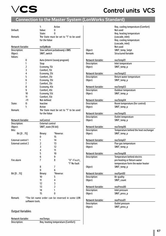
67
Control units VCSConnection to the Master System (LonWorks Standard)
1: ActiveDefault: Value: 0 State: 0Remark: The State must be set to "1" to be used for the Value
Network Variable: nviOpModeDescription: Stav zařízení požadovaný z BMSObject: SNVT_switchValues: 0 Auto (interní časový program) 1 Stop 2 Economy, 1St 3 Comfort, 1St 4 Economy, 2St 5 Comfort, 2St 6 Economy, 3St 7 Comfort, 3St 8 Economy, 4St 9 Comfort, 4St 10 Economy, 5St 11 Comfort, 5St >11 Not definedState: 0: Inactive 1: ActiveRemark: The State must be set to "1" to be used for the Value
Network Variable: nviControlDescription: External controlObject: SNVT_state (16 bit)Bits: Bit [0 ...15] Binary: *Reverse: 0 15 External control 1 1 14 External control 2 2 13 3 12 4 11 5 10 6 9 Fire alarm 7 8 " 0 " = F a u l t , "1" No fault 8 7 9 6 Bit [0 ...15] Binary: *Reverse: 10 5 11 4 12 3 13 2 14 1 15 0
Remark: *The bit name order can be reversed in some LON software tools.
Output Variables
Network Variable: nvoTempsDescription: Req. heating temperature (Comfort)
Req. cooling temperature (Comfort) Not used Req. heating temperature (cascade, inlet) Req. cooling temperature (cascade, inlet) Not usedObject: SNVT_temp_SetptRemark: Structured Variable
Network Variable: nvoTemp01Description: Inlet temperatureObject: SNVT_temp_p
Network Variable: nvoTemp02Description: Return water temperatureObject: SNVT_temp_p
Network Variable: nvoTemp03Description: Outdoor temperatureObject: SNVT_temp_p
Network Variable: nvoTemp04Description: Room temperature (for control)Object: SNVT_temp_p
Network Variable: nvoTemp05Description: Outlet temperatureObject: SNVT_temp_p
Network Variable: nvoTemp06Description: Temperature behind the heat exchangerObject: SNVT_temp_p
Network Variable: nvoTemp07Description: Flue gas temperatureObject: SNVT_temp_p
Network Variable: nvoTemp08Description: Temperature behind electric pre-heating or Return water temperature form the water heaterObject: SNVT_temp_p
Network Variable: nvoPpm00Description: Air qualityObject: SNVT_count
Network Variable: nvoPress00Description: Inlet pressureObject: SNVT_press_p
Network Variable: nvoPress01Description: Outlet pressureObject: SNVT_press_p

68
Connection to the Master System (LonWorks Standard)Network Variable: nvoPress02Description: Not usedObject: SNVT_press_p
Network Variable: nvoPress_Flow00Description: Current request for the inlet fanObject: SNVT_flowRemark: %, Pa or l/s
Network Variable: nvoPress_Flow01Description: Current request for the outlet fanObject: SNVT_flowRemark: %, Pa or l/s
Network Variable: nvo_Flow00Description: Inlet air-flowObject: SNVT_flow
Network Variable: nvo_Flow01Description: Outlet air-flowObject: SNVT_flow
Network Variable: nvoPerc00Description: Heater outputObject: SNVT_lev_count
Network Variable: nvoPerc01Description: Cooling outputObject: SNVT_lev_count
Network Variable: nvoPerc02Description: Heat exchanger outputObject: SNVT_lev_count
Network Variable: nvoPerc03Description: Mixing outputObject: SNVT_lev_count
Network Variable: nvoPerc04Description: Not usedObject: SNVT_lev_count
Network Variable: nvoPerc05Description: Electric heater output Object: SNVT_lev_count
Network Variable: nvoPerc06Description: Inlet fan outputObject: SNVT_lev_count
Network Variable: nvoPerc07Description: Outlet fan outputObject: SNVT_lev_count
Network Variable: nvoPerc08Description: Not usedObject: SNVT_lev_count
Network Variable: nvoPerc09Description: Air humidity in the inletObject: SNVT_lev_count
Network Variable: nvoPerc10Description: Air humidity in the roomObject: SNVT_lev_count
Network Variable: nvoPerc11Description: Outdoor air humidityObject: SNVT_lev_count
Network Variable: nvoPerc12Description: Humidification outputObject: SNVT_lev_count
Network Variable: nvoPerc13Description: Dehumidification outputObject: SNVT_lev_count
Network Variable: nvoPerc14Description: Electric after-heater outputObject: SNVT_lev_count
Network Variable: nvoAHum00Description: Absolute humidity in the inletObject: SNVT_abs_humid
Network Variable: nvoAHum01Description: Absolute humidity in the outletObject: SNVT_abs_humid
Network Variable: nvoOpModeDescription: Current device stateObject: SNVT_switchValues: 0 Stop 1 Operation (Comfort) 2 Operation (Economy) 3 Not used 4 Optimized start 5 Night chilling 6 Temperature start-up 7 Night turn-over 8 Not used 9 Fire 10 Safety stop 11 Fan run-down 12 Start >12 Not definedState: 0: Inactive :Mode Auto 1: Active :Mode OSDefault: Value: 0 State: 0
Network Variable: nvoSwitch00Description: Current fan stateObject: SNVT_switchValues: 0 Stop 1 1St 2 2St
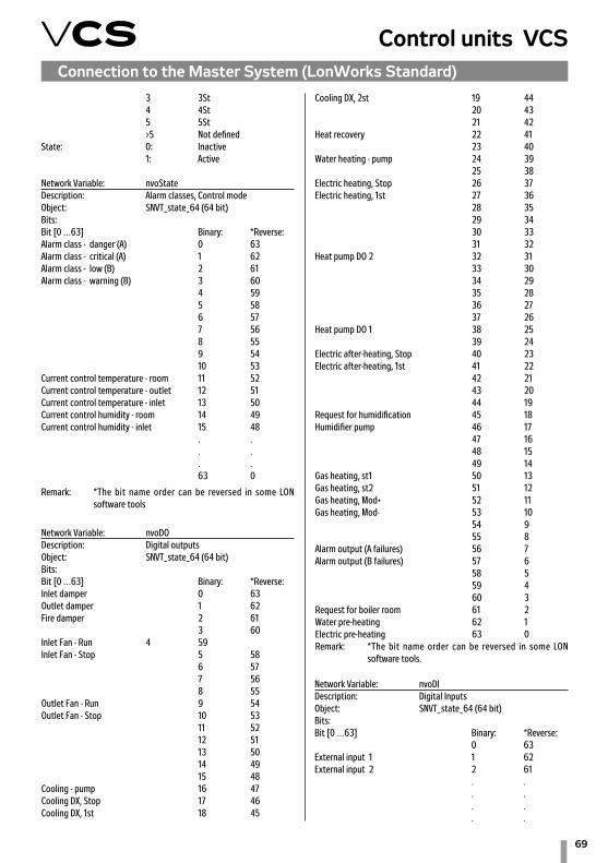
69
Control units VCSConnection to the Master System (LonWorks Standard)
3 3St 4 4St 5 5St >5 Not definedState: 0: Inactive 1: Active
Network Variable: nvoStateDescription: Alarm classes, Control modeObject: SNVT_state_64 (64 bit)Bits: Bit [0 …63] Binary: *Reverse:Alarm class - danger (A) 0 63Alarm class - critical (A) 1 62Alarm class - low (B) 2 61Alarm class - warning (B) 3 60 4 59 5 58 6 57 7 56 8 55 9 54 10 53Current control temperature - room 11 52Current control temperature - outlet 12 51Current control temperature - inlet 13 50Current control humidity - room 14 49Current control humidity - inlet 15 48 . . . . . . 63 0
Remark: *The bit name order can be reversed in some LON software tools
Network Variable: nvoDODescription: Digital outputsObject: SNVT_state_64 (64 bit)Bits: Bit [0 …63] Binary: *Reverse:Inlet damper 0 63Outlet damper 1 62Fire damper 2 61 3 60Inlet Fan - Run 4 59Inlet Fan - Stop 5 58 6 57 7 56 8 55Outlet Fan - Run 9 54Outlet Fan - Stop 10 53 11 52 12 51 13 50 14 49 15 48Cooling - pump 16 47Cooling DX, Stop 17 46Cooling DX, 1st 18 45
Cooling DX, 2st 19 44 20 43 21 42Heat recovery 22 41 23 40Water heating - pump 24 39 25 38Electric heating, Stop 26 37Electric heating, 1st 27 36 28 35 29 34 30 33 31 32Heat pump DO 2 32 31 33 30 34 29 35 28 36 27 37 26Heat pump DO 1 38 25 39 24Electric after-heating, Stop 40 23Electric after-heating, 1st 41 22 42 21 43 20 44 19Request for humidification 45 18Humidifier pump 46 17 47 16 48 15 49 14Gas heating, st1 50 13Gas heating, st2 51 12Gas heating, Mod+ 52 11Gas heating, Mod- 53 10 54 9 55 8Alarm output (A failures) 56 7Alarm output (B failures) 57 6 58 5 59 4 60 3Request for boiler room 61 2Water pre-heating 62 1Electric pre-heating 63 0Remark: *The bit name order can be reversed in some LON software tools.
Network Variable: nvoDIDescription: Digital InputsObject: SNVT_state_64 (64 bit)Bits: Bit [0 …63] Binary: *Reverse: 0 63External input 1 1 62External input 2 2 61 . . . . . . . .

70
Connection to the Master System (LonWorks Standard)Pressure differences (air-flow), outlet 49 14 50 13Outdoor air humidity 51 12Air humidity difference, inlet 52 11Air humidity difference, room 53 10Dew point 54 9 55 8Air quality 56 7 57 6 58 5 59 4 60 3 61 2 62 1 63 0
Remark: *The bit name order can be reversed in some LON software tools
63 0Remark: *The bit name order can be reversed in some LON software tools
Network Variable: nvoDODescription: AlarmsObject: SNVT_state_64 (64 bit)Bits: Bit [0 …63] Binary: *Reverse:Dampers 0 63Fire dampers 1 62Burner failure 2 61Inlet fan 3 60Outlet fan 4 59Fans – operating hours 5 58Back-up inlet fan 6 57Back-up outlet fan 7 56Cooling 8 55Flue-gas high temperature - AHU shut down 9 54Heat recovery 10 53 11 52Heat recovery (antifreeze protection) 12 51 13 50Mixing 14 49Flue-gas high temperature - heater shut down 15 48Heating, pump 16 47Water heating 17 46Electric heating 18 45Back draught protection (TH) 19 44Heat pump Cooling 20 43 21 42Heat pump, heating 22 41 23 40Electric after-heating 24 39 25 38Humidifier, pump 26 37Humidification 27 36 28 35Fire 29 34Electric pre-heating 30 33Filters 31 32Outdoor temeprature 32 31Inlet temperature 33 30Return water temperature 34 29Room temperature 1 35 28Room temperature 2 36 27Outlet temperature 37 26 38 25 39 24 40 23 41 22 42 21 43 20 44 19Temperature, HMI SG 1,2 45 18Inlet temperature difference 46 17Room temperature difference 47 16Pressure differences (air-flow), inlet 48 15

71
Control units VCSConnection to the Master System (ModBus Standard)
Modbus RTU Slave (BMS)The VCS control unit enables integration of the centralized BMS (Building Management System) using the Modbus communication bus. Using a suitably integrated system, it is possible to control the air-handling device operating state. Specifications of the variables (data points) used for integra-tion are described in the section Description of Pre-defined Variables in the Modbus Network. The final functionality, monitoring and control options will be dependent on the inte-grator used to ensure connection to the master BMS system.
GenerallyModbus is a worldwide recognized standard defined by Modbus Organization, Inc.The Modbus Organization is a group of independent suppliers of automation devices. The Modbus Organization administers and develops communication systems for distributed auto-mation systems. It also provides information to obtain and share information about the protocols, their application and certification to simplify implementation by users with the aim to reduce expenses for communication. For detailed information on the Modbus RTU protocol, refer to www.modbus.org.
Trademarks and CopyrightThe trademarks used in this document are listed on the back page, including their owners. These trademarks are quoted from Siemens materials.
Modbus RTU ProtocolThe Modbus communication protocol works using the Master/Slave principle. The Slave function is used for the VCS control unit communication with the master system. Thus, the VCS control unit behaves like a Slave during communication and expects requests from the Master (master system).There are two variants of the Modbus protocol serial transfer mode. The VCS control unit uses the RTU (Remote Terminal Unit) mode. Therefore, a unique Modbus RTU identification is very important.The RS 485 standard is used to transfer the data through a half-duplex twin-lead.The transfer lead (cable) must be selected depending on this standard and other conditions. For more information, refer to www.modbus.orgCorrect wiring must be carried out to ensure proper operation – 115/230 V AC must be strictly isolated from 24 V SELV AC. There are three terminals, "+", "-" and reference voltage ter-minal "REF", available in the control unit to connect the VCS control unit to the bus. To ensure correct functioning of the bus, the first and last device on the bus must be fitted with a terminal resistor. Therefore, it is possible to perform software settings of the terminal resistor in the VCS control unit for the Modbus Slave (see the Data Points in the VCS Installation and Operating Instructions).It is also necessary to set other communication parameters in the VCS control unit data points (section – Communication with Modbus RTU Master System).
Default values of the data points for the Slave Modbus RTU:
• Slave address – 1• Baud rate – 9600 Bd • Parity - None • Number of stop bits – 2• Response time limit – 5 s
For more information, refer to the List of Data Points Note: Once these data points have been set, the device must be re-started. After the restart, the device is ready to communicate in accordance with the set parameters.
Modbus RegistersThe Modbus registers are divided according to their properties. For a general description and explanation of the registers, refer to the table below:
Data types used to transfer the values:16-bit for real values (Unsigned Word)16-bit for status values (Signed Word)1-bit for status values like 0=Off (switched off) and 1=On (switched on) 1-bit for alarm values like 0=Alarm and 1=Normal (OK)
Divisor (Multiplier):The so-called Divisor (Multiplier) is used for values which need the decimal numbers to be transferred. For example, for tem-peratures the value Divisor (Multiplier) of 10 is used to enable a one decimal place value to be transferred. For example, a temperature of 23.2°C is transferred by the Modbus as 232. The number must be divided by 10 to get the correct value. For information indicating this fact, refer to the note for a particular data point.
ModbusType Reference Description
Coil Status 0xxxx Read/Write Discrete Out-puts or Coils.
Input Status 1xxxx Read Discrete Inputs.
Input Register 3xxxx Read Input Registers.
Holding Reg-ister 4xxxx Read/Write Output or
Holding Registers.
Table 8 – Modbus registers

72
Connection to the Master System (ModBus Standard)
Description of Pre-defined Variables in the Modbus NetworkThis section includes a description of variables (registers) according to the assigned REMAK data points. The list below includes specifications of variables for different VCS control system variants at the discretion of REMAK a.s. For example, if the VCS control system (air-handling device) has not been equipped with gas heating, it will not be possible to use these variables.
Coil status (Read/Write)
Input states (Read)
Adress Description Values/Units Remarks
0x0001 Alarm acknowledge 0-1 Off*On
0x0002
0x0003
0x0004
0x0007
0x0011
0x0012 Ext control input 1 0-1 Off*On
0x0013 Ext control input 2 0-1 Off*On
0x0014
0x0015 Fire alarm 0-1 OK*Alarm
Adress Description Values/Units Remarks
1x0001 Alarm class danger (A) 0-1 Off*On
1x0002 Alarm class critical (A) 0-1 Normal*Alarm
1x0003 Alarm class low (B) 0-1 Normal*Alarm
1x0004 Alarm class warning (B) 0-1 Normal*Alarm
1x0005
1x0011
1x0012 Ext control input 1 0-1 Off*On
1x0013 Ext control input 2 0-1 Off*On
1x0014
1x0015
1x0020
1x0021
1x0022
1x0023
1x0024
1x0026 Fan alarm 0-1 OK*Alarm

73
Control units VCS
1x0027 Supply fan alarm 0-1 OK*Alarm
1x0028 Supply fan fdbk 0-1 OK*Alarm
1x0029 Sply fan deviation 0-1 Passive*Active
1x0030 Exhaust fan alarm 0-1 OK*Alarm
1x0031 Exhaust fan fdbk 0-1 OK*Alarm
1x0032 Exhaust fan deviation 0-1 Passive*Active
1x0033 Fan op hours alarm 0-1 Passive*Active
1x0036 Cooling DX alarm 0-1 OK*Alarm
1x0037
1x0038 Cooling pump alarm 0-1 OK*Alarm
1x0039
1x0040 Heat recovery alarm 0-1 OK*Alarm
1x0041
1x0042
1x0043 Hrec frost monitor 0-1 OK*Alarm
1x0044
1x0045 Htg pump alarm 0-1 OK*Alarm
1x0046
1x0047 Htg frost monitor 0-1 OK*Frost
1x0048 El htg alarm 0-1 OK*Alarm
1x0049
1x0050
1x0051
1x0052
1x0053
1x0054
1x0055
1x0056 El heating 2 alarm 0-1 OK*Alarm
1x0057 Sply tmp deviation 0-1 Passive*Active
1x0058 Room tmp deviation 0-1 Passive*Active
1x0059
1x0062
1x0063
1x0064
Connection to the Master System (ModBus Standard)
Adress Description Values/Units Remarks
Input states (Read) (continuation)

74
1x0065
1x0066
1x0067
1x0070 Filter alarm 0-1 OK*Alarm
1x0071 Supply filter alarm 0-1 OK*Alarm
1x0072 Exh filter alarm 0-1 OK*Alarm
1x0073 Fire alarm 0-1 OK*Alarm
1x0074 Supply tmp fire alm 0-1 OK*Alarm
1x0075 Exh tmp fire alarm 0-1 OK*Alarm
1x0076
1x0077
1x0078 Modbus comm alarm 0-1 OK*Alarm
1x0080 Outside air temp °C OK*Alarm
1x0081 Supply air temp °C OK*Alarm
1x0082 Heating frost tmp °C OK*Alarm
1x0083 Room temperature °C OK*Alarm
1x0084 Room temperature 2 °C OK*Alarm
1x0085 Return air temp °C OK*Alarm
1x0086 Exhaust air temp °C OK*Alarm
1x0087
1x0088
1x0089
1x0090
1x0091
1x0092
1x0093
1x0094
1x0095
1x0096
1x0097
1x0098
1x0099
1x0100 Air quality ppm OK*Alarm
1x0101
Adress Description Values/Units Remarks
Input states (Read) (continuation)
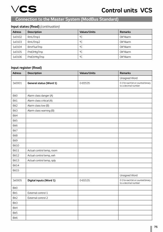
75
Control units VCSConnection to the Master System (ModBus Standard)
1x0102 RmUTmp1 °C OK*Alarm
1x0103 RmUTmp2 °C OK*Alarm
1x0104 BrnrFlueTmp °C OK*Alarm
1x0105 PreElHtgTmp °C OK*Alarm
1x0106 PreEtrHtgTmp °C OK*Alarm
Adress Description Values/Units Remarks
Input register (Read)
Unsigned Word
3x0001 General status (Word 1) 0-65535 0-1 for each bit or counted binary to a decimal number
Bit0 Alarm class danger (A)
Bit1 Alarm class critical (A)
Bit2 Alarm class low (B)
Bit3 Alarm class warning (B)
Bit4
Bit5
Bit6
Bit7
Bit8
Bit9
Bit10
Bit11 Actual control temp, room
Bit12 Actual control temp, exh
Bit13 Actual control temp, sply
Bit14
Bit15
Unsigned Word
3x0005 Digital inputs (Word 1) 0-65535 0-1 for each bit or counted binary to a decimal number
Bit0
Bit1 External control 1
Bit2 External control 2
Bit3
Bit4
Bit5
Bit6
Input states (Read) (continuation)Adress Description Values/Units Remarks

76
Connection to the Master System (ModBus Standard)
Input register (Read) (continuation)
Bit7
Bit8
Bit9
Bit10
Bit11
Bit12
Bit13
Bit14
Bit15
3x0006 Digital inputs (Word 2) 0-65535 0-1 for each bit or counted binary to a decimal number
Bit0
Bit1
Bit2
Bit3
Bit4
Bit5
Bit6
Bit7
Bit8
Bit9
Bit10
Bit11
Bit12
Bit13
Bit14
Bit15
Unsigned Word
3x0009 Digital outputs (Word 1) 0-65535
Bit0 Supply (Exhaust) dampers
Bit1
Bit2
Bit3
Bit4 Supply fan, running
Bit5 Supply fan, off
Bit6
Adress Description Values/Units Remarks

77
Control units VCSConnection to the Master System (ModBus Standard)
Bit7
Bit8
Bit9 Exhaust fan, running
Bit10 Exhaust fan, off
Bit11
Bit12
Bit13
Bit14
Bit15
3x0010 Digital outputs (Word 2) 0-65535 0-1 for each bit or counted binary to a decimal number
Bit0 Cooling pump
Bit1 Cooling DX, off
Bit2 Cooling DX, stage 1
Bit3 Cooling DX, stage 2
Bit4
Bit5
Bit6
Bit7
Bit8 Heating pump
Bit9
Bit10 Electrical heating, off
Bit11 Electrical heating, st1
Bit12
Bit13
Bit14
Bit15
3x0011 Digital outputs (Word 3) 0-65535 0-1 for each bit or counted binary to a decimal number
Bit0 Heat pump DO 2
Bit1
Bit2
Bit3
Bit4
Bit5
Bit6 Heat pump DO 1
Input register (Read) (continuation)Adress Description Values/Units Remarks

78
Bit7
Bit8 Extra el heating, off
Bit9 Extra el heating, stage 1
Bit10
Bit11
Bit12
Bit13
Bit14
Bit15
3x0012 Digital outputs (Word 4) 0-65535 0-1 for each bit or counted binary to a decimal number
Bit0
Bit1
Bit2 Burner heating, st1
Bit3 Burner heating, st2
Bit4 Burner heating, Mod+
Bit5 Burner heating, Mod-
Bit6
Bit7
Bit8 Alarm output, high
Bit9 Alarm output, low
Bit10
Bit11
Bit12
Bit13 Heating demand
Bit14 PreWtrHeating
Bit15 PreEl.Heating
Unsigned Word
3x0013 Alarms (Word 1) 0-65535
Bit0
Bit1
Bit2 Burner failure
Bit3 Supply fan
Bit4 Exhaust fan
Bit5 Fan operating hours
Bit6 Supply back up
Bit7 Exhaust back up
Connection to the Master System (ModBus Standard)
Adress Description Values/Units Remarks
Input register (Read) (continuation)

79
Control units VCS
Bit8 Cooling
Bit9 OverHeat Burner heating
Bit10 Heating recovery
Bit11
Bit12 Heating recovery frost
Bit13
Bit14 Heating recovery damper
Bit15 Flue-gas high temperature, heater shut down
3x0014 Alarms (Word 2) 0-65535 0-1 for each bit or counted binary to a decimal number
Bit0 Heating pump
Bit1
Bit2 Electrical Heating
Bit3 Burner fan overrun TH
Bit4 Heat pump cooling
Bit5
Bit6 Heat pump heating
Bit7
Bit8 Extra Electrical Heating
Bit9
Bit10
Bit11
Bit12 PreWtrHeating
Bit13 Fire Alarm (external alarm)
Bit14 Electric pre-heating
Bit15 Filter Alarm
3x0015 Alarms (Word 3) 0-65535 0-1 for each bit or counted binary to a decimal number
Bit0 Out temperature
Bit1 Supply temperature
Bit2 Heating frost temperature
Bit3 Room1 temperature
Bit4 Room2 temperature
Bit5 Exhaust temperature
Bit6 Extract temperature
Bit7
Bit8
Input register (Read) (continuation)
Connection to the Master System (ModBus Standard)
Adress Description Values/Units Remarks

80
Bit9
Bit10
Bit11
Bit12
Bit13 Room unit 1,2 - temperature
Bit14 Supply temperature deviation
Bit15 Room/Exh temp deviation
3x0016 Alarms (Word 4) 0-65535 0-1 for each bit or counted binary to a decimal number
Bit0 Supply press/flow deviation
Bit1 Exhaust press/flow deviation
Bit2
Bit3
Bit4
Bit5
Bit6
Bit7
Bit8 Air quality
Bit9
Bit10
Bit11
Bit12
Bit13
Bit14
Bit15
Unsigned Word
3x0017 Act operating mode 0-12 Present value
0=Off
1=On/Comfort
2=Economy
3=Na
4=Osstp
5=NightClg
6=UnOcc
7=NightKick
9=Fire
10=Stop
Input register (Read) (continuation)
Connection to the Master System (ModBus Standard)
Adress Description Values/Units Remarks

81
Control units VCS
11=OverRun
12=StartUp
12=Start
3x0018 Act fan step 0-5 Off*Stage1*Stage2*Stage3*Stage4*Stage5
3x0019
3x0020 Op mode man st/tmp 0-11 Auto*Off*Eco St1*Comf St1*Eco St2*Comf St2*Eco St3*Comf St3*Eco St4*Comf St4*Eco St5*Comf St5
3x0021
3x0022 TSP steps/tmp 0-10 Off*Eco St1*Comf St1*Eco St2*Comf St2*Eco St3*Comf St3*Eco St4*Comf St4*Eco St5*Comf St5
3x0023 Act Opmode ext ctrl 0-6 Auto*Off*Stage 1*Stage 2*Stage 3*Stage 4*Stage 5
3x0024
3x0025 Supply (Exhaust) air damper cmd 0-1 Off*On
3x0026
3x0027
3x0028 Supply fan cmd 0-6 Off*Stage 1*Stage 2*Stage 3*Stage 4*Stage 5
3x0029 Sply fan outp sign 0-100%
3x0030 Exhaust fan cmd 0-6 Off*Stage 1*Stage 2*Stage 3*Stage 4*Stage 5
3x0031 Exh fan outp signal 0-100%
3x0032
3x0033 Cooling outp signal 0 - 100%
3x0034 Cooling pump cmd 0-1 Off*On
3x0035 Cooling DX cmd 0-2 Off*Stage 1*Stage 2
3x0036 Hrec outp signal 0 - 100%
3x0037
3x0038 Hrec dmpr outp sign 0 - 100%
3x0039
3x0040 Heating outp signal 0 - 100%
3x0041 Htg pump cmd 0-1 Off*On
Input register (Read) (continuation)
Connection to the Master System (ModBus Standard)
Adress Description Values/Units Remarks

82
3x0042 El htg outp signal 0 - 100%
3x0043 El heating cmd 0-1 Off*On
3x0044 Heat pump Cooling 0 - 100%
3x0045 Heat pump 0 - 100%
3x0046 Heat pump state 0-2 None*Cooling*Heating
3x0047 Heat pump Heating 0 - 100%
3x0048
3x0049 El htg 2 outp sign 0 - 100%
3x0050 El heating 2 cmd 0-1 Off*On
3x0051
3x0052
3x0053
3x0054
3x0055
3x0057
3x0058
3x0059
3x0060 Alarm output 0-1 Normal*Alarm
3x0061
3x0062
3x0064 Act airquality comp 0 - 100%
3x0065 Act fan clg value 0 - 100%
3x0066 Act fan htg value 0 - 100%
3x0067 Act fan comp tmp 0 - 100%
3x0068
3x0069
3x0070
3x0072 Outside air temp `-x.y - +x.y °C (factor 10)
3x0073 Supply air temp `-x.y - +x.y °C (factor 10)
3x0074 Heating frost tmp °C (factor 10)
3x0075 Valid room tmp °C (factor 10)
3x0076 Return air temp °C (factor 10)
3x0077 Exhaust air temp °C (factor 10)
3x0078
Input register (Read) (continuation)
Connection to the Master System (ModBus Standard)
Adress Description Values/Units Remarks

83
Control units VCSConnection to the Master System (ModBus Standard)
3x0079
3x0080
3x0081
3x0082
3x0083
3x0084
3x0085
3x0086
3x0087
3x0088
3x0089
3x0090
3x0091
3x0092
3x0093
3x0095
3x0096
3x0097
3x0098
3x0099
3x0101 Air quality 0 – x ppm
3x0102
3x0104 Act heating stpt `-x.y - +x.y °C
3x0105 Act cooling stpt °C
3x0106 Act sply htg stpt °C
3x0107 Act sply clg stpt °C
3x0108
3x0109
3x0110
3x0111
3x0112 Act sply fan stpt 0-100% (0 - x l/s)
3x0113 Act exh fan stpt 0-100% (0 - x l/s)
3x0114
3x0115
Input register (Read) (continuation)Adress Description Values/Units Remarks

84
3x0116
3x0117
3x0130 Burner flue temp °C (factor 10)
3x0131 PreEl. heating temp °C (factor 10)
3x0132 PreWater heating temp °C (factor 10)
3x0133 Burner damper 0-100%
3x0200 RoomUnitsActRmUMode 0-3 Auto*Comf*StBy*Eco
3x0210 RoomUnitsActSpvShift °C
3x0211 RmUTmp1 °C
3x0212 RmUTmp2 °C
Unsigned Word
Input register (Read) (continuation)
Connection to the Master System (ModBus Standard)
Adress Description Values/Units Remarks
4x0001 Control bits 0-65535
Bit0
Bit1 External control 1
Bit2 External control 2
Bit3
Bit4
Bit5
Bit6
Bit7 Fire alarm (external alarm)
Bit8
Bit9
Bit10
Bit11
Bit12
Bit13
Bit14
Bit15
Unsigned Word
Present value
4x0005 Device state – BMS request (version w/o temeperature air handling
0-6 Auto*Off*St1*St2*St3* St4*St5
Holding register (Read/Write) [03:H]Adress Description Values/Units Remarks

85
Control units VCS
4x0006 Device state – BMS request 0-11 Auto*Off*Eco St1*Comf St1*Eco St2*Comf St2*Eco St3*Comf St3*Eco St4*Comf St4*Eco St5*Comf St5
4x0007
4x0008
4x0009 Op mode man st/tmp 0-11 Auto*Off*Eco St1*Comf St1*Eco St2*Comf St2*Eco St3*Comf St3*Eco St4*Comf St4*Eco St5*Comf St5
4x0010
4x0011
4x0012
Signed Word
PresentValue
4x0020 (factor 10)
4x0021
4x0022 Comfort htg stpt °C
4x0023 Comfort clg stpt °C
4x0024
4x0025
4x0026 Economy htg stpt °C
4x0027 Economy clg stpt °C (factor 10)
4x0028
4x0029
4x0030
4x0031
4x0032
4x0033
4x0034
4x0035
4x0036 Sply max limit `-x.y - +x.y °C (factor 10) Higt limit
4x0037 Sply min limit `-x.y - +x.y °C (factor 10) Low limit
4x0039
4x0040
4x0041
4x0042
Holding register (Read/Write) [03:H] (continuation)
Connection to the Master System (ModBus Standard)
Adress Description Values/Units Remarks

86
4x0043
4x0044
4x0045
4x0046
4x0047
4x0048
4x0049
4x0050 Sply fan st1 stpt 0 - x l/s %, Pa or l/s
4x0051 Sply fan st2 stpt
4x0052 Sply fan st3 stpt
4x0053 Sply fan st4 stpt
4x0054 Sply fan st5 stpt
4x0055
4x0056 Exh fan st1 stpt 0 - x l/s %, Pa or l/s
4x0057 Exh fan st2 stpt
4x0058 Exh fan st3 stpt
4x0059 Exh fan st4 stpt
4x0060 Exh fan st5 stpt
4x0061
4x0062 Air quality stpt CO 0 - x ppm
4x0063 Air quality stpt CO2, VOC 0 - x ppm
TrackingValueCOM
4x0064 Outside air temp `-x.y - +x.y °C (factor 10)
4x0065
4x0066 Room temperature °C
4x0067
Advanced mode
Signed Word
PresentValue
4x0070
4x0071
4x0072
4x0073
4x0074
4x0075
4x0076
Holding register (Read/Write) [03:H] (continuation)
Connection to the Master System (ModBus Standard)
Adress Description Values/Units Remarks

87
Control units VCS
4x0077
4x0078
4x0079
4x0080
4x0081
4x0082 CaseFlowLimtMinDev °C (factor 10)
4x0083 CaseFlowLimtMaxDev °C (factor 10)
4x0084
4x0085
4x0086
4x0087
4x0088
4x0089
4x0090
4x0091
4x0092
4x0093
4x0094
4x0095
4x0096
4x0097
4x0098
4x0099
4x0100
4x0101
4x0102
4x0103
4x0104
4x0105
4x0106
4x0107
4x0108
4x0109
4x0110
4x0111
4x0112
4x0113
Holding register (Read/Write) [03:H] (continuation)
Connection to the Master System (ModBus Standard)
Adress Description Values/Units Remarks
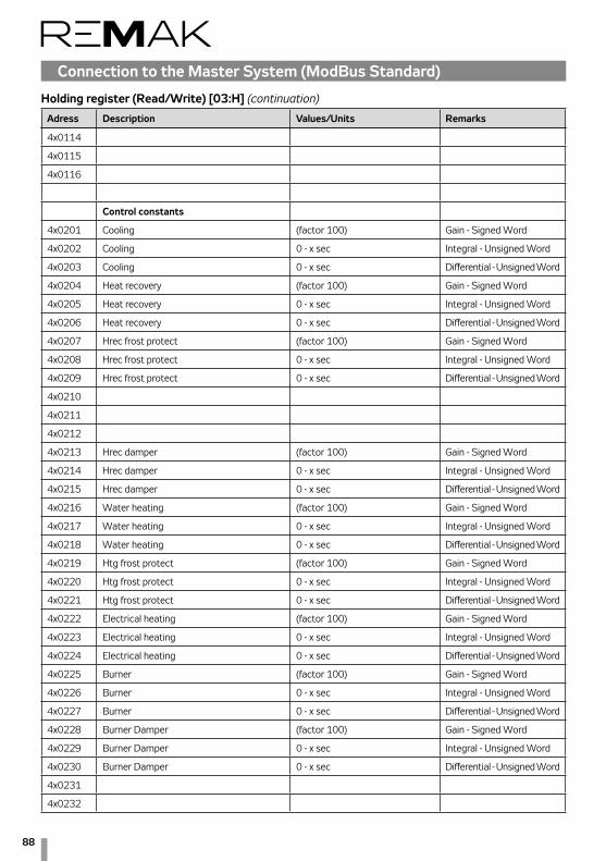
88
4x0114
4x0115
4x0116
Control constants
4x0201 Cooling (factor 100) Gain - Signed Word
4x0202 Cooling 0 - x sec Integral - Unsigned Word
4x0203 Cooling 0 - x sec Differential - Unsigned Word
4x0204 Heat recovery (factor 100) Gain - Signed Word
4x0205 Heat recovery 0 - x sec Integral - Unsigned Word
4x0206 Heat recovery 0 - x sec Differential - Unsigned Word
4x0207 Hrec frost protect (factor 100) Gain - Signed Word
4x0208 Hrec frost protect 0 - x sec Integral - Unsigned Word
4x0209 Hrec frost protect 0 - x sec Differential - Unsigned Word
4x0210
4x0211
4x0212
4x0213 Hrec damper (factor 100) Gain - Signed Word
4x0214 Hrec damper 0 - x sec Integral - Unsigned Word
4x0215 Hrec damper 0 - x sec Differential - Unsigned Word
4x0216 Water heating (factor 100) Gain - Signed Word
4x0217 Water heating 0 - x sec Integral - Unsigned Word
4x0218 Water heating 0 - x sec Differential - Unsigned Word
4x0219 Htg frost protect (factor 100) Gain - Signed Word
4x0220 Htg frost protect 0 - x sec Integral - Unsigned Word
4x0221 Htg frost protect 0 - x sec Differential - Unsigned Word
4x0222 Electrical heating (factor 100) Gain - Signed Word
4x0223 Electrical heating 0 - x sec Integral - Unsigned Word
4x0224 Electrical heating 0 - x sec Differential - Unsigned Word
4x0225 Burner (factor 100) Gain - Signed Word
4x0226 Burner 0 - x sec Integral - Unsigned Word
4x0227 Burner 0 - x sec Differential - Unsigned Word
4x0228 Burner Damper (factor 100) Gain - Signed Word
4x0229 Burner Damper 0 - x sec Integral - Unsigned Word
4x0230 Burner Damper 0 - x sec Differential - Unsigned Word
4x0231
4x0232
Holding register (Read/Write) [03:H] (continuation)
Connection to the Master System (ModBus Standard)
Adress Description Values/Units Remarks

89
Control units VCS
Holding register (Read/Write) [03:H] (continuation)
Connection to the Master System (ModBus Standard)
Adress Description Values/Units Remarks
4x0233
4x0234 El. reheating (El. heating 2) (factor 100) Gain - Signed Word
4x0235 El. reheating (El. heating 2) 0 - x sec Integral - Unsigned Word
4x0236 El. reheating (El. heating 2) 0 - x sec Differential - Unsigned Word
4x0237
4x0238
4x0239
4x0240
4x0241
4x0242
4x0243
4x0244
4x0245
4x0246
4x0247
4x0248
4x0249
4x0250
4x0251
4x0252
4x0253
4x0254
4x0255 Supply fan (factor 100) Gain - Signed Word
4x0256 Supply fan 0 - x sec Integral - Unsigned Word
4x0257 Supply fan 0 - x sec Differential - Unsigned Word
4x0258 Exhaust fan (factor 100) Gain - Signed Word
4x0259 Exhaust fan 0 - x sec Integral - Unsigned Word
4x0260 Exhaust fan 0 - x sec Differential - Unsigned Word
4x0261
4x0262
4x0263
4x0264
4x0265
4x0266
4x0267
4x0268
4x0269

90
4x0270 Air quality (factor 100) Gain - Signed Word
4x0271 Air quality 0 - x sec Integral - Unsigned Word
4x0272 Air quality 0 - x sec Differential - Unsigned Word
4x0273 Casc controller tmp (factor 10) Gain - Signed Word
4x0274 Casc controller tmp 0 - x sec Integral - Unsigned Word
4x0275
4x0276
4x0277 HeatPumpHtg (factor 100) Gain - Signed Word
4x0278 HeatPumpHtg 0 - x sec Integral - Unsigned Word
4x0279 HeatPumpHtg 0 - x sec Differential - Unsigned Word
4x0280 HeatPumpClg (factor 100) Gain - Signed Word
4x0281 HeatPumpClg 0 - x sec Integral - Unsigned Word
4x0282 HeatPumpClg 0 - x sec Differential - Unsigned Word
4x0283 ElPreHtg (factor 100) Gain - Signed Word
4x0284 ElPreHtg 0 - x sec Integral - Unsigned Word
4x0285 ElPreHtg 0 - x sec Differential - Unsigned Word
4x0283 WtrPreHtg (factor 100) Gain - Signed Word
4x0284 WtrPreHtg 0 - x sec Integral - Unsigned Word
4x0285 WtrPreHtg 0 - x sec Differential - Unsigned Word
Holding register (Read/Write) [03:H] (pokračování)
Connection to the Master System (ModBus Standard)
Adress Description Values/Units Remarks

91
Control units VCS
List and Description of Basic Data Points
Connection to the Master System (BacNet Standard)
BACnet/IP (BMS)The VCS control unit enables integration of the centralized BMS (Building Management System) using the BACnet/IP communication standard. Using a suitably integrated mas-ter system, it is possible to control the air-handling device's operating state.
GenerallyBACnet is a standard communication protocol for Building Automation and Control Networks developed by ASHRAE (American Society of Heating, Refrigerating and Air-condition-ing Engineers). The main goal was to create a protocol which enables the integration of systems from different manufactur-ers intended for building automation. For detailed information on the BACnet protocol, refer to the following websites:
www.bacnet.orgwww.bacnetinternational.net
BACnet/IP ProtocolThere are several variants of the BACnet protocol. The VCS control system uses BACnet/IP for the Ethernet network. The BACnet communication protocol works using the Master/Slave principle. The Server function is used for VCS unit system communication with the master system. This means that the VCS control unit behaves like a Server in the communication. Protocol settings can be performed using one of the follow-ing controllers: HMI, DM, TM or Web. Switching on and off,
restart and other settings of the BACnet server can be carried out through the web page (calling the address set in the VCS control unit). For detailed information on the BACnet/IP Stand-ard (EDE file and others) settings and application, refer to the Siemens BACnet/IP Communication Module documentation available on the REMAK website.
The following table includes a list of basic data points which can be used for this communication and their description. The list includes specifications of variables for different VCS control system variants.
For example, if the VCS control system (air-handling device) has not been equipped with gas heating, it will not be possible to use these variables. The final functionality, monitoring and control options will be dependent on the integrator used to ensure connection to the master BMS system.
Data point name MeaningDevice Device
Diagnostic Diagnostics
SystemClock System time
AirQuality Air quality
RoomTmp Room temperature
RmUTmp1 HMI-SG1
RmUTmp2 HMI-SG2
ValidRoomTmp Temperature in the room after control
ReturnAirTmp Outlet air temperature
SupplyTmp Inlet air temperature
OutTmp Outdoor temperature
HtgFrstTmp Return water temperature (water heater)
ExhaustTmp Outlet air temperature after the heat exchanger
PreElHtgTmp Temperature, electric pre-heating
PreWtrHtgTmp Return water temperature (water pre-heating)
BrnrFlueTmp Flue gas temperature
RoomHum Air humidity in the room - relative
SupplyHum Inlet air humidity - relative
OutHum Outdoor air humidity - relative
RmHumAbs Absolute air humidity in the room
SplyHumAbs Absolute inlet air humidity
OutHumAbs Absolute outdoor air humidity
RmEnth The room - enthalpy
OutEnth Outdoor enthalpy
ActOpMode Current state of the device
ActFanStep Current state of the fans
OpModeAutoManSt.Swtch Manual mode (control)
OpModeAutoManStTmp.Swtch Manual mode (control)

92
Connection to the Master System (BacNet Standard)
OpModeBmsTimeSt.Swtch BMS control mode (control, master system)
OpModeBmsTimeStTmp.Swtch BMS control mode (control, master system)
TmpSpv.CoSpvHtg Required value for heating - Comfort
TmpSpv.CoSpvClg Required value for cooling - Comfort
TmpSpv.EcSpvHtg Required value for heating - Economy
TmpSpv.EcSpvClg Required value for cooling - Economy
HumSpvRel.SpvHum Required value for humidification (relative)
HumSpvRelSpvDehum Required value for dehumidification (relative)
AirQSpv Required value for air quality
ScheduleSt Weekly time schedule
ScheduleStTmp Weekly time schedule
CalendarEx Exception time schedule
CalendarOff Switch-off schedule
ActCascSpvHtg Current required heating temperature (cascade)
ActCascSpvClg Current required cooling temperature (cascade)
ActCascSpvDeh Current required value for dehumidification (cascade)
ActCascSpvHum Current required value for humidification (cascade)
Heating.Pos Heating node valve outlet position
ElectricalHtg.Pos Electric heating outlet position
Cooling.Pos Cooling valve outlet position
ExtraElHtg.Pos Electric after-heating outlet position
Hrec.Pos Heat exchanger control outlet position
HrecDamp.Pos Mixing damper outlet position
aoHeatPumpHtg.Pos Heat pump outlet position - heating
aoHeatPumpClg.Pos Heat pump outlet position - cooling
HumidityCtrl.Pos Humidification current value
DeHumidity.PrVal Dehumidification current value
AirQCmp.PrVal Air quality compensation current value
SplyFan.Cmd.St Current stage, inlet fan
ExhFan.Cmd.St Current stage, outlet fan
Heating.Pmp.Cmd.OnOff Heating pump state
ElectricalHtg.CmdSt.St Electric heater state
ExtraElHtg.CmdSt.St Electric after-heater state
Cooling.Pmp.Cmd.OnOff Water cooler pump state
Cooling.CmdDx.St Cooling state, inverter cooling unit
Damper.Exh.OnOff Damper, outlet
Damper.Sply.OnOff Damper inlet
AlmOutHigh Alarm, output A
AlmOutLow Alarm, output B
AlmCl0 Alarm, class A
AlmCl1 Alarm, class A
AlmCl2 Alarm, class B
AlmCl3 Alarm, class B
FireAlm External alarm
AckAlmPls Failure release
List and Description of Basic Data Points ((continuation))

93
Control units VCSPLC Controller for Compressor Output Control
Safety MeasuresCheck the correct supply voltage (see Technical Data) before connecting the device. Do not expose the device to moisture or water. Use the devise so that the operating conditions will not be exceeded and the device will not be exposed to abrupt changes in temperatures at high humidity causing air humidity condensation.Warning: Disconnect all power supply connections before you start any maintenance work on the device.The sensors must be located out of reach of the end user. Do not disassemble the device. If the device fails or malfunctions, send it back, including a detailed description of the failure.
General DescriptionThe PLC controller controls cooling in the air-conditioned room depending on the signals received from the parent system and pre-set parameters. It measures temperature in the compressor discharge and pressure in the heat exchangers. If the device is fitted with a 4-way valve (Premium" version), it is possible to switch the unit between cooling (in summer) and heating (in winter) modes of the ventilated room, including heat recovery. For a more detailed description of this technol-ogy, refer to the User Manual. The device is equipped with preparations for a differential pressostat in the air-handling unit channel, serving as antifreeze protection of the evapora-tor. The signal received from this switch will start defrosting by directing inlet air to the evaporator's fins. Defrosting starts automatically if the limit evaporation temperature is set below 4°C, when ice build-up is created on the evaporator's surfaces which need to be defrosted. If the differential pressostat is not present, defrosting can also be set for time cycles using the parameters. Evaporation pressure is used to monitor the de-vice and the unit's output is reduced to protect the evaporator against freezing at low evaporation temperatures. Condensa-tion pressure monitoring is another way of providing device protection. When this value is increased, the unit's output is reduced to prevent a failure. The output reduction is signalled by the relay contact – KA7. The output reduction level can also be signalled by 0-10V analogue outputs. One signal's reduction is based on the evaporation temperature and the other one is based on the condensation temperature. The device is able to control condensation pressure using an analogue output. This feature is only available for the "Premium" version.
Process ControlControl is started as soon as the contacts for the unit start are closed. Relay – KA9. If the unit is equipped with reversation, the cooling or heating mode is selected.
LED Mode Function
On Unit start is requested
On Cooling in operation
On Heating in operation
On Defrosting in progress
On Power valve switched on
On Alarm
On No function
On Measured units
On Programming Menu
Flashes Remembers the Prog. Menu password for 60 s
1 FA1 circuit breaker open
2 FA2 circuit breaker open
3 Low-pressure pressostat open
4 High-pressure pressostat open or incorrect phase sequence
5 Electronic injection valve failure
6 Output limiting relay closed
The selection is made by the relay – KA11 (closed = heating). Then the unit output is controlled by the 0-10V analogue signal. Operation of the unit is indicated by a dry contact, the same way as an error. The unit is equipped with several protections, protecting the cooling device against damage (pressure switches, outlet temperature monitoring, etc.).
Controller OperationSET(F4) Shows the user parameters. In the programming mode, it is used to select the parameter or confirm the operation. ESC(F2) In the programming mode, it is used to cancel the operation. Cancels the action. Long hold = Failure reset (F1) No Function
(F3) No Function Key combination:
SET(F2) + Esc (F4) Enters the programming mode.

94
PLC Controller for Compressor Output Control
Viewing Temperatures and Alarms
Viewing Temperatures1. Briefly press the SET button to display "Pen". 2. Using the arrows, scroll to "Prb" and press the SET
button to confirm.3. Scroll to the temperature analogue input (Anxx) and
press the SET button to confirm.4. The display shows the temperature of the corresponding
sensor.
Viewing Analogue Output Values1. Briefly press the SET button to display "Pen".2. Using the arrows, scroll to "AO" and press the SET
button to confirm.3. Scroll to the analogue output (AOnxx) and press the SET
button to confirm.4. The display shows the value of the corresponding
analogue output.
Viewing Alarms1. Briefly press the SET button to display "Pen".2. Using the arrows, scroll to "AL" and press the SET
button to confirm.3. A corresponding alarm is displayed. If more than one
alarm is displayed, use the arrows to scroll between them.
Main Functions
Viewing and Changing Basic Parameters1. Briefly press the SET button to display "USr".2. Press the SET button to confirm.3. Using the arrows, scroll to the desired parameter and
press the SET button to confirm.4. Using the arrows, change the value and press the SET
button to confirm.5. To return to the menu, press the ESC button.
Changing Values of any ParameterSimultaneously press the SET + ESC buttons to switch the device to the programming mode (the indicator comes ON). At the same time, the "Par" is displayed. Press the SET but-ton to confirm. Using the or buttons, select the parameter group and press the SET button to confirm.Using the or buttons, select the parameter.Press the SET button to display its current value. Using the or buttons, set the new value of the parameter.Press the SET button to save the value.Exit: To return to the main screen, press the ESC button or wait 60 seconds.Note: Some parameters require a code to be displayed.
Hidden ParametersTo display hidden parameters, enter a code when opening the programming menu. 1. Simultaneously press the SET + ESC buttons to switch
the device to the programming mode (the indicator comes ON). At the same time, "Par" is displayed.
2. Using the buttons, select "PASS" and press the SET button to confirm.
3. Using the buttons, enter the numerical code required for the parameter group in question (Level 1 or 2) and press the SET button to confirm.
4. Then proceed in the same way as in point 6.2. Now the parameters are visible.
Exit: To return to the main screen, press the ESC button or wait 60 seconds.
Parameters
User Parameters (S---)n S-00 Pre-set evaporation temperature (-10.0 to 10.0°C): A value limiting the unit's output depending on the evaporation temperature.n S-01 Pre-set condensation temperature (30.0 to 90.0°C): A value limiting the unit's output depending on the condensation temperature.n S-02 Condenser settings (20.0 to S-01°C): A pre-set value of the condensation pressure to control the condenser fans. If used.n S-04 Start (Yes/No): If "Yes" is set, the unit is started at 100 % output regardless of the input signal control value. Level 1 (PASS = 1) – only for service (P---)n P-16 Maximum compressor discharge temperature (90.0 to 140.0 °C): When this temperature is exceeded, the compressor is switched off.n P-20 Minimum compressor runtime (5 to 120 sec): If the compressor is switched on, it can only be switched off once this time has elapsed. This is a safety value.n P-21 Minimum compressor off time (30 to 300 sec): If the compressor is switched off, it can only be switched on once this time has elapsed. This is a safety value.n P-22 PWM valve switching period (10 to 20 sec): Switching period of the digital compressor power valven P-23 Pen HP (3 to 10 sec): Allowed number of high-pressure pressostat failures per P-24 time.n P-24 Pei HP (15 to 60 sec): Time interval for counting high-pressure pressostat failures.n P-25 Pen LP (3 to 10 sec): Allowed number of low-pressure pressostat failures per P-24 time.n P-26 Pei LP (15 to 60 sec): Time interval for counting low-pressure pressostat failures. Level 2 (PASS = 2) – only for service (P---)n P-01 PID LP Udz: PID control upper insensitive zone.n P-02 PID LP Ldz: PID control lower insensitive zone.n P-03 PID LP Bp: PID control proportionality zone.n P-04 PID LP Ti: PID control integration constant.n P-05 PID LP Td: PID control derivative constant.n P-06 PID LP Arw: PID control anti-reset lift.n P-07 PID LP Speed: Maximum number of PID output changes per 1 sec.n P-10 Hyst UP Ext: Upper hysteresis for the cooling unit start. When this limit is exceeded, the input analogue signal is accepted.

95
Control units VCSPLC Controller for Compressor Output Control
Viewing AlarmsIf a failure occurs during operation, this state is signalled by a flashing symbol . Furthermore, the corresponding alarm can be displayed. For a description, refer to point 5.2.
Alarm Types
Application Version Settings
One compressor with output control, BASIC version -1
Two compressors, BASIC version - 2
One compressor without output control, PREMIUM version 1
Two compressors, PREMIUM version 2
Code Cause Description
A-01 LP sensor failure Check 4-20mA current loop.
A-02 Td sensor failure
Check the tempera-ture sensor.
A-03 HP sensor failure Check 4-20mA current loop.
A-04 Compressor 1 failure 1
Check the compres-sor protections.
A-05 Compressor 2 failure
Check the compres-sor protections.
A-06 HP failure Number of HP pressostat failures exceeded.
A-07 LP failure Number of LP pressostat failures exceeded.
A-08 Control sig. failure Check 0-10V signal.
A-09 Expanding module failure
Expanding module does not respond.
A-10 EEV failure Expansion valve failure.
A-11 Condenser failure
Check the condenser circuit breaker.
n P-17 Coolant: Used coolant type. (0= R404A, 1=R22,2=R744, 3 = R290, 4 = R134A, 5 = R407C, 6 = R410A, 7 = R427A, 8 = R507A).n P-32 PID HP Udz: PID control upper insensitive zone.n P-33 PID HP Ldz: Control lower insensitive zone n P-34 PID HP Bp: Control proportionality zone n P-35 PID HP Ti: Control integration constantn P-36 PID HP Td: Control derivative constantn P-37 PID HP Arw: Control anti-reset liftn P-38 PID HP Speed: Maximum number of PID output changes per 1 sec.n P-40 Bypass time LP: Low-pressure pressostat bypass time upon compressor start.n P-41 Filter time LP: Low-pressure pressostat bypass time when the compressor is running.n P-42 Bypass time LPA: Low-pressure sensor failure bypass time upon compressor start.n P-43 Filter time LPA: Low-pressure sensor bypass time when the compressor is running.n P-45 Curb Enable: Output limitation enable from the PID high-pressure controller.n P-47 Warning time (0 to 600 sec): Time for which the output limitation is signalled.n P-50 PID Cond Bp: PID control proportionality zone.n P-51 PID Cond Ti: Control integration constantn P-52 PID Cond Td: Control derivative constantn P-53 PID Cond Udz: PID control upper insensitive zone.n P-54 PID Cond Ldz: PID control lower insensitive zonen P-55 PID Cond Speed: Maximum number of PID output changes per 1 sec.n P-56 PID Cond Arw: Control anti-reset lift.n P-48 Warning value (0 to 100%): PID controller limiting value – when exceeded, the output limitation is signalled.n P-60 Increment time (10 to 600 sec): Additional compressor connection time. n P-61 Decrement time (0 to 120 sec): Additional compressor switch-off delay time. n P-66 Dif. through En.: Enables use of the differential pressostat information for the cooling heat exchanger. Anti-freeze protection. It starts defrosting.n P-67 Swap time: Cooling/heating mode switching time. n P-68 Det time: Maximum defrosting time. n P-69 Dit time: Defrosting interval. n P-70 Switch OFF: The compressor is switched off when switching cooling/heating modes.n P-71 Switch Cap.: (0 to 100%) Compressor output between cooling/heating mode switching. n P-74 Defrost LP: (-10.0 to 2.5°C) Evaporation pressure limit compared with S-00 below when defrosting is enabled. n P-77 Maf: Number of cycles for the pressure oscillation mathematical filter. n P-79 App: Application selection.

96
Additional Display Views (P-79 parameter)
Code Description
Outr The sensor is out of the measuring range.
An06 Digital compressor discharge temperature.
An10 Evaporation temperature
An11 Condensation temperature
An12 Evaporation pressure
An13 Condensation pressure
An14 Inlet temperature 1
An15 Inlet temperature 2
AIL3 Input signal value (0 = 0V, 100 = 10V)
AIL4 LP sensor value (bar)
AIE4 HP sensor value (bar)
AOL3 Limiting value according to Te
AOE3 Limiting value according to Tc
AOE4 Condenser control analogue signal value
FrEE Electronics Menu active, only for service pur-poses.
PLC Controller for Compressor Output Control
Packaging Self-extinguishing ABS plastic
Box Front panel, 32 × 74 mm, depth 80 mm
Panel degree of protection IP65
Connection Screw terminal box for wires up to 2.5 mm2 cross-section
Supply voltage 12, 24 V AC
Input power Max. 6 VA
Display Four-digit, red LEDs, digit height 14.2 mm
Inlets Up to 5 sensors NTC (-40 to 110°C)
Additional inputs 6x digital tension-free contact
Relay outputs 4x switching relay, 2A, 250 V AC
Triac outputs 1x triac relay, 2A, 250 V AC
Analogue outputs 1× conf., 2× 0–10V
Data memory EEPROM
Operating temperature range -10°C to 55°C
Storing temperature range -20°C to 85°C
Relative humidity 10 to 90 % (non-condensing)
Measuring and control range Depending on the sensor used
Accuracy (at ambient temperature 25 °C) ± 0,7 °C ±1 digit
Technical Data

97
Control units VCSPLC Controller for Compressor Output Control
Code Description Range: Def.
S-00 Set Te -10.0…10.0°C 4.1
S-01 Set Tc 30.0…90.0°C 63.0
S-02 Set Cond 20.0…S-01°C 17.0
S-04 Full output Yes…No 15.0
P-01 PID LP_Udz --- 0
P-02 PID LP Ldz --- 0
P-03 PID LP BP --- 40.0
P-04 PID LP Ti --- 120.0
P-05 PID LP Td --- 0
P-06 PID LP Arw --- 1
P-07 PID LP Speed --- 0
P-10 Hyst UP 5…20 % 10
P-16 Set Td 90.0…140.0°C 120.0
P-17 Coolant type 0 – 9 5
P-20 Min T on 5…120 sec 30
P-21 Min T off 30…300 sec 60
P-22 PWM period 10…20 sec 10
P-23 Pen HP 3…10 3
P-24 Pei HP 15…60 min 15
P-25 Pen LP 3…10 3
P-26 Pei LP 15…60 min 15
P-32 PID HP_Udz --- 0
P-33 PID HP Ldz --- 0
P-34 PID HP BP --- 20.0
P-35 PID HP Ti --- 100.0
P-36 PID HP Td --- 0
P-37 PID HP Arw --- 1
P-38 PID HP Speed --- 0
P-40 BLP Bypass --- sec 30
P-41 BLP Filter --- sec 4
P-42 BLPA Bypass --- sec 60
P-43 BLPA Filter --- sec 120
P-45 Curb En --- Yes
P-47 Warning time 0…600 sec 60
P-48 Warning value 0…100 % 10
P-50 PID Cond BP --- 15.0
Standard Setting Values
P-51 PID Cond Ti --- 100.0
P-52 PID Cond Td --- 0
P-53 PID Cond _Utz --- 0
P-54 PID Cond Ldz --- 0
P-55 PID Cond Speed --- 0
P-56 PID Cond Arw --- 1
P-60 T inc 10…600 sec 60
P-61 T dec 0…120 sec 10
P-66 DP En --- No
P-67 Swap time --- sec 30
P-68 Def time --- sec 30
P-69 Def interval --- hod 6
P-70 Switch off --- Yes
P-71 Switch Cap 0…100 % 30
P-74 Defrost LP -10,0…2,5 °C 4,0
P-77 Maf --- 100
P-79 App --- -1

98
To keep the system reliable, it is advisable to change the battery every year.
Electronic Expansion Valve Overheating Controller EC3-X33
Safety InstructionsRead these Operating Instructions carefully. Incorrect use can result in serious damage to the device and personal injury. Installation can only be performed by a suitably qualified and experienced person. Before starting the installation, all power supply sources must be disconnected. Temperatures must be within the specified ranges.All connections must comply with the applicable electrical regulations in force.The device must not be connected to voltage until all electrical connections have been connected.
Warning: The EC3-X33 controller is equipped with a renew-able backup source containing lead and acids. Therefore, it cannot be disposed along with normal waste – the battery is subject to waste recycling regulations. In any case, it must be recycled in accordance with the applicable regulations in force (98/101/EEC).
LocationThe EC3-X33 controller can be installed on the DIN bar. The EC3-331 controller is designed to be installed on the DIN bar. Position: On a vertical plate with the output for the step motor situated only on the upper side.
Electrical Connection
Zapojení podle schématuThe device may only be connected to the power supply once all conductors have been connected in accordance with the wiring diagram.The device cover is grounded to the 6.3 mm terminal.
Warning: To comply with the applicable regulations (especially CEI 107-70), it is necessary to ensure the following: T trans-former 24 V AC must be double insulated in Class II. Power supply 24 V AC is not grounded. To eliminate mutual influence and grounding problems, it is recommended to use separate condensers for the EC3 and other devices. If connected to the mains, the EC3 will be destroyed.
Power supply 24 VAC ±10%, 50/60 Hz Class II
Energy consumption 25 VA max. EC3-X32, incl. EX 4-8
Terminal box Push-in type for 0.14 … 1.5 mm2 conductors
Grounding 6.3 mm grounding connector
Degree of protection IP20
Connection to ECD-002 ECC-N** or category 5 conductor with RJ45
Digital Input I 0 / 24V DC/AC for ON/OFF control
NTC input ECN-N60, output temperatures from the evaporator
Inlet pressure input, 4-20mA PT5/07M;PT5/18M;PT5/30M Alco Controls
Output 4-20mA for other controller K 12/24V
Deviation from the input signal Max. ± 8%
Failure relay H SPDT 24 V DC/AC 2 A ind
ON Failure-free operation
OFF Failure or disconnected power supply
Output for EX4 to 8 valves
at 24 V DC, max. 0.8 A
Teplota okolí
0...60 °C
1...25 °C (the longest battery service life)
> 35 °C (battery service life < 2 years)
If the output relay is not used, the user must ensure proper safety regarding power supply breakdown-related failures.
Technical Data

99
Control units VCS
Commissioning PreparationsExhaust coolant from the corresponding part of the cooling circuit. Warning: The EX valve is delivered in the open position – it must be closed before it is filled with coolant.Connect the EC3 to 24V while the digital input I is open (0V) – the valve will be closed. Once the valve has been closed, the circuit can be filled with coolant.
Warning: Settings of the EC3 must be performed before the valve is connected to voltage. Digital input I must not be connected to 24V before all the parameters are set. ECD-002 can be connected to EC3 in the G socket using an ECC-Nxx conductor or another common Class 5 cable equipped with RJ 45 connectors.
The basic purpose of this relay is to protect the sys-tem when the power supply fails, if the communication interface or ECD-002 is not used.
Digital input I operation according to com-mands for the compressor/thermostat
It controls: Operating conditions digital input
CompressorCompressor start closed/24V
(start)
Compressor stop opened/0V (stop)
Thermostat
Command (com-pressor is running)
closed/24V (start)
No command opened/0V (stop)
Electronic Expansion Valve Overheating Controller EC3-X33
Wiring Diagram
Conductor Marking and PurposeE EX valve connection using terminated cable (A white, B black, C brown, D blue)F EX8 (respectively EX7) valve connection – only terminal G Auxiliary control device H Failure relay – no voltage when the power supply is switched off or failure signal receivedI Digital input: 0V = open (stop); 24V = closed (start) J Class II transformer – power supply 24V AC/25 VA K External controller – usually not ALCO (output from EC3 can be used)

100
ECD-002 Display with Buttons (LED Indicators and Settings)
Settings of Main Parameters on ECD-002 (before start)Make sure the digital input I is without voltage, then it is pos-sible to connect the terminal to 24V.Important: When the digital input is switched off (0V), the main parameters will be set as follows: Coolant Type (u0), Pressure Sensor Type (uP) and Valve Type (ut).These parameters must be set at voltage of 0V to prevent damage to the valve or compressor due to the transfer of the setting changes to the controlled element.To make it easy, the setting procedure is described at the end of this manual. Once these parameters have been set and saved, the other functions can be set during operation.
Start-upStart the system and verify it for proper overheating settings. The EC3-X33/53 controller can work even without the con-nected ECD-002 display. The ECD is mainly used to set the desired actions.
Setting Procedure using ECD-002The device settings are protected by a digital code. The de-fault factory setting is "12". To enter the program, proceed as follows:- Press and hold the PRG button for more than 5 seconds, 0 will start flashing.- Using the or buttons, set 12 as the password and press the SEL button to confirm.- Then the first parameter (/1) to be set is displayed. Change the settings using the procedure below:- Using the or buttons, select the parameter code to be changed.
Flashes: The valve closes.On: The valve opens.
Flashes: The valve opens.On: The valve is open
Settings: Parameter
Parameter selection
IncreasesScrolls
Decreases value
On: Command to runOff: N/AFlashes: Exhaust
Prg & Sel (5 sec)Manual reset of the flashing code
On: AlarmOff: N/A
Electronic Expansion Valve Overheating Controller EC3-X33
- Press the or button to increase or decrease the value.- Press the SEL button to confirm the new value and continue to the next parameter.The process still repeats: "press the or to set on the display..."
To exit the parameter change modePress the PRG button to confirm the new values and close the setting process of the newly changed parameters.
To exit without changing any parameter:Do not touch any button for the next 60 seconds (time for setting will elapse).
Reset – Recovery of Default Factory Settings- Make sure the digital input is without voltage (0V). - Simultaneously press the and buttons for more than 5 seconds, "0" will display.- Using the or button, set the password "12" and press the SEL button to confirm. - If a different password is used, this new password is set and A0 will appear.- Press the SEL button to reset the device – the default factory settings will be restored. - Press the PRG button to exit and save the default factory settings
Valve Build-Up Time at Start (parameters uu and u9)

101
Control units VCSElectronic Expansion Valve Overheating Controller EC3-X33
Main Parameters – change if other settings are desired
Additional properties (set if necessary)
Code Parameter description and options Min. Max. Factory settings
Actual settings
H5 Password 1 199 12
u0Coolant: 0 7 1
0 = R22 1 = R134a 2 = R507 3 = R404A 4 = R407C 5 = R410A 6 = R1247 = R744 (subcritical conditions)
uPThe used sensor type: 0 1 0
0 = PT4-07M (for R22/R134a/R507/R404A/R407C/R124) 1 = PT4-18M (for R410A)2 = PT4-30M (for R744, subcritical)
utThe used valve type: 1 5 5
1 = EX4 2 = EX5 3 = EX6 4 = EX7 5 = EX8
uu Initial opening of the valve (%) 10 100 50u9 Valve opening time (seconds) 1 30 5
uLLow overheating reporting 0 2 10 = N/A (for flooded evaporator) 1 = Yes with auto-reset 2 = No with manual resetswitches at 0.5K (if it lasts 1 min); switches immediately at 3K
u5Rated overheating (K)If uL used (auto run) 3 30 6If uL not used 0.5 30 6
u2MOP function 0 1 10 = Yes 1 = No
u3
MOP settings (°C), saturated temperature * * XSet by the manufacturer according to the used coolant.+13°C for R22 +15°C for R134a +7°C for R507 +7°C for R404A +15°C for R407C+15°C for R410A+50°C for R124
5Used units (only for u3, u5, 1 0 1 00 = °C, K, bar 1 = °F, R, psig(Psig is divided by 10 - example: displayed 12.5 equals 125 psig)
1Displayed value 0 4 00 = measured overheating 1 = measured evaporating pressure, (bar); 2 = valve opening (%), 3 = measured water output temperature 4 = calculated evaporation temperature (°C) from measured pressure
u4Overheating control method 0 1 00 = normal, 1 = slow
b1 Action of the battery if it fails. 0(only for EC3-X33), according to the table:
*) Maximum and minimum values are dependent on the coolant type
Number Display Failure relay Valve Reset option after replacement0 – – controls –1 Ab – controls –2 Ab switches fully closed automatically3 Ab (flashes) switches fully closed manually
If b1 is set to 0 or 1, the user must ensure suitable protection to protect the system against failures caused by power supply breakdowns.

102
Electronic Expansion Valve Overheating Controller EC3-X33
ECD-002 Display InstallationThe ECD-002 display can be connected at any time during operation. The EC2-371 is integrated into a 71 x 29mm panel – see dimensional drawing. Insert the device into the panel (1).The swivel lugs must be inserted into the device edges. Use the provided Allen wrench and turn the openings in the front face to move the lugs along the guides until they contact the panel wall (2).Using the wrench, tighten both lags to the back panel wall so that the device cannot move – see figure (3).
Data to be permanently displayed on the display can be selected (parameter 1). Temporarily, other data can also be displa-yed. This function cannot be set during a failure. The display shows numerical values for 1 second (see parameter 1) and then the selected parameter. After 5 minutes, it returns to the selected parameter 1.
Troubleshooting
Check of System Operating Conditions
1 2
3
Code Cause Function Relay H Valve Remedy Reset
E0 Pressure sen-sor failure closes closes Check PT4 sensor and its connection. Auto
E1 Temperature sensor failure closes closes Check NTC sensor and its connection. Auto
A EX valve not connected closes Check the valve wiring and power supply. Auto
AbDefective
battery
b1=1 working Low capacity, charge or replace the battery. If the signal is weak once the battery has been charged, replace the battery. This can happen if the battery has not been used for a long time.
Ab b1=2 closes closes
Ab flashes b1=3 closes closes Manual
Er Display error Data for the display are out of its range. Check the sensors. Auto
Note: If more failures occur at the same time, the most serious failure is valuated and displayed first before the other less seri-ous failures. Operating data will be displayed once all failures have been resolved.
Message "---" (no data displayed): Display shows only dashes "---" during start and if no data for display are available.
Failure Possible reason Remedy
Operational over-heating differs from pre-set overheating
Defective sensors
- Check the connection. ECN-N60 temperature sensor must be used.- PT4 pressure sensor must be used according to the manual for the given coolant.- The sensor conductors must be routed apart from the power conductors.
Low overheating – wet operation
- Defective sensors- Incorrect el. connection of the EX valve
Check the sensors and connections of the valve - EC3, el. conductor.
The valve does not close - The digital input I is energized.- Wrong parameters The valve will close if the input is energized, I = 0V. Check the settings
Unstable overheat-ing – cycling Unsuitable evaporator Select higher overheating – find stable settings
The valve performs contrary in relation to the EX3 command
Incorrect el. connection Connect the conductor colours correctly according to the wiring diagram.
The valve will not open at high pressure difference
Incorrect settings of the "u" parameter Check and adjust the settings
Overheating change after some time
The motor needs to be synchronized
The digital input must not be permanently energized with 24V, it is necessary to switch off the power 1x per week for 5 seconds if the compressor does not stop.
Attention! DO NOT tighten too much to prevent the lugs to be broken.

103
Control units VCSElectronic Expansion Valve Overheating Controller EC3-X33
Illustrative Procedure of EC3-X33 and ECD-002 Settings
Dimensions
EX3-X33EX3-X33EX3-X33 ECD-002
Data display

104
Unit Activation
Unit ActivationCheck the correct interconnection of the control unit and air-handling unit. Check the motors (frequency inverters) - power part, controls, dampers, filter pressure sensors, motors, sen-sors… - in accordance with the air-handling unit. Check the locations of the sensors, check the mechanical parts (dampers, motors) for free rotation and sticking. Fan pressure and differential pressure sensing hoses must be situated so that they will sense static pressure (the end of the hose must not be oriented against the air flow. It must be oriented perpendicularly or in the direction of the air flow).Depending on the operating mode, a large quantity of con-densate can be created inside the unit. Before starting the unit, it is advisable to check the condensate drainage circuit, especially the correct height of the siphons (according to the fan pressure), correct interconnection of the siphons – indi-vidual siphons must not be hermetically connected, filling of siphons with water and free passage through the piping.
Differential Pressure Sensor Setting InspectionOn the filters: Set the value of the final pressure loss in ac-cordance with the rating plate data.On the heat exchanger: The values are also indicated on the rating plate. They are derived from the operating pressure loss of the heat exchanger.If the results of the inspection are OK, connect the distribution board to the power supply but still maintain the STOP mode.Enter the "Inputs" item in the service menu of the controller and check the state and functionality of the digital inputs (by short circuiting the cable ends or disconnecting the cable).Stay in the "Inputs" item in the service menu of the control-ler and using the documentation check that the displayed values for the sensors correspond to reality (compare with a calibrated thermometer). If in doubt about the correct sensor, disconnect the sensor and check the displayed value.Check the position of the dampers (inlet and outlet dampers closed, short-circuit damper open), failure-free operating state.If the system indicates a failure, trace the failure, check the component indicating the failure and remove the failure.If no failures are indicated, test/simulate possible failures. At-tention! Some failures can only be recalled when the device is running, e.g. air flow failure. Reset the failures.Go to the service menu of the controller and test in sequence individual elements of the unit (dampers, heat exchanger, heater, heat pump, circulation pumps and fans). Switch to manual mode and test functionality (positions of damper, opening of valves, direction of turning of fans). Once the testing is finished, return all items to the AUTO mode.
Note: This way of testing ensures switching off in case of a failure. When testing by direct switching of the outputs, no protection is functional.
Impeller k-factor
RH 22 C 47
RH 25 C 60
RH 28 C 75
RH 31 C 95
RH 35 C 121
RH 40 C 154
RH 45 C 197
RH 50 C 262
RH 56 C 308
RH 63 C 381
RH 71 C 490
RH 80 C 620
RH 90 C 789
RH 10 C 999
RH 11 C 1233
Unicon Air Flow Sensor SettingsSensor operation (Mode) – set to 5.00Adjust measuring range in Pa (in accordance with max. pres-sure of the fan).Set the k-factor in accordance with the fan impeller type, see Table.

105
Control units VCSUnit Activation
To ensure stepless air-flow control using the Unicon sensor and to prevent the fan output cycling, we recommend setting the frequency inverter start-up and run-down ramps to 180 s (Danfoss frequency inverter –parameters 3-41 and 3-42).If the system is equipped with a PLC controller for compressor output control, it is necessary to follow the provided Operat-ing Instructions, especially to check and remove possible failure messages. The controller has already been set and the parameters need not be adjusted, with only some exceptions.Now it is possible to switch the unit to RUN mode (see chapter 4.1 Main Switch).Check the fan current consumption in each operating mode. If higher than Imax (see motor rating plate), it must be decreased (e.g. by decreasing the max. frequency of the frequency inverter).
Current Date and Time SettingsAccording to the customer's requirements, set the desired temperature and humidity at full operating mode (e.g. 31°C, 50%) and at reduced operating mode (e.g. 28°C, 70%). It is also necessary to set the time schedule for full operating mode (time of swimming pool use, e.g. 9.00-20.00 h).Outside this time, the unit is operated in reduced operating mode.If the air-handling unit is equipped with the Unicon constant air flow sensor, set this required air flow in the Carel control-ler menu. The swimming-pool unit should be constantly in operation, except for service and maintenance periods.The system is filled with a calculated quantity of coolant in the factory.
Coolant HandlingThe used HFC type coolants (e.g. R404A, R407C, R410A,…) fall into the category of monitored greenhouse substances in accordance with European Parliament and Council Direc-tive EC 842/2006 on F-gases (Art. 3, par. 6) and CZ Act no. 483/2008 Sb on air conservation. The user of a cooling device containing ≥3kg of coolant is obliged to keep records on results of periodic leak tests, the so-called Cooling Device Service Book, which must include the following data:n Volume and type of coolant used during unit installationn Results of performed preventive checks, especially the results of leakage testsn Volume of added or drained coolant when performing maintenance or during unit operation or liquidation.The records must include identification of the personnel or company who performed the maintenance or servicing. Any checks or intervention into the cooling circuit may only be performed by personnel certified by the Ministry of Health of the Czech Republic. On request, the user must submit the logs to the appropriate control authority.The frequency of checks is determined by the volume of coolant: up to 30 kg ….. once a yearup to 300 kg … twice a year
If a leak is found, it must be removed immediately. Repeat leakage tests of the circuit must be performed one month after the repair to verify the repair’s efficiency.

106
KHD-S1_ _.R Backup System Wiring Diagram
Function descriptionUnit start and operating mode (heating/cooling) can be selected by an external signal. The E2 heat exchanger is alternatively used for heating or cooling of fresh air supplied to the air-conditioned object. The heat potential of the outlet air is always used. In winter, the outlet air transfers the heat to the E1 heat exchanger. Thus, heat recovery is achieved. The unit works in heat pump mode. The valve is without power. Cold inlet air is heated in the E2 heat exchanger (condenser). In summer, fresh air is cooled as needed in the E2 heat exchanger. The SV valve is energized and the 4-way valve is moved to the opposite position. The E2 heat exchanger now works as an evaporator. Relatively cold outlet air exhausted from the building effectively cools the E1 heat exchanger (condenser). Surplus heat is transferred out of the building. Proper functionality of the system is ensured by the control switchboard (RKJ) with the integrated PLC control system. The application software optimises the unit's operation and protects it against overloading. The heat recovery level can be step-lessly controlled (0…10V signal) depending on the inlet air temperature TA (behind the E2 heat exchanger). If the maximum permissible condensation temperature is reached, the output is automatically reduced. The system is also protected against freezing of the evaporator by an automatically limited lowest evaporation temperature.
Note: The 4-way valve is displayed in the "cooling" position (SV without power); the E1 heat-exchanger is in evaporator mode.
Legend:C1 Cooling compressor SV1 Power valve SV 4-way valve SG Sight glassEX Expansion valvesE1, 2 Evaporator/condenserTd, Ts Temperature sensorsZ1-4 Back valvesLP Low-pressure pressostatHP High-pressure safety pressostatRKJ Unit power and control distribution boardTA Room temperature
Header
Valve in position without power
Building wall
Fresh air
Relief air
C1SV1
SVHP
(21/28bar)HPA
LP(1.7/2.7bar)
LPA
Z3
Z4
Z1
Z2
RKJ
EX1
EX2
TD
(Cu8 -50)
E1
E2
Filtr
SG
TA
Faults
Main switch
Filter
0...10 V
Capacity control
Mode: Heat/Cool
ON/OFF
Unit Alarm
4...20 mA
4...20 mA
HPComp
Failure

107
Control units VCS
The VCS Control unit can optionally be equipped with one or two outputs for remote signalling.Depending on the configuration, the following:n Only failure (non-potential contact, max. load 230 V/1 A)n Failure and operation (2 non-potential contacts, max. load 230 V/1 A).
Checks
Temperature Difference MonitoringThis enables the difference between the required and actual supply air or room temperature to be monitored. The moni-tored temperature is compared with the pre-set tolerance ±°C while simultaneously monitoring the temperature drop below the minimum limit. If the monitored temperature is below the minimum limit or outside the permissible tolerance for more than 1 hour, an informative error will be activated. The optional temperature difference monitoring can be enabled using the HMI controller, refer to the chapter Additional Operating Modes and Function Setting Options. Temperature minimum limit or tolerance can be set using the HMI controller in the List of Data Points in the section Monitored temperature Check Settings, System and Network Setting – Difference Monitoring.
FailuresThe VCS unit monitors, evaluates and informs about various types of system failures. Possible failures are indicated, see the chapter of appropriate HMI controller (SG, TM, DM or Web) or Remote Indication. Failure messages identify failed objects/components which need to be inspected, respec-tively to find and remove the cause of the failure (or confirm absence of any problem) before acknowledging the failure. For failure reset, refer to the chapters of HMI controllers.
Failure Inputs (digital) All important air-handling unit components (fan motors, elec-tric heaters, etc.) are equipped with failure inputs (contacts) which after being connected to the devoted inputs (terminals) are evaluated by the VCS unit, respectively by the controller. If a failure (incorrect state of the contact) occurs, the VCS control unit will automatically put out an alarm in accordance with an internal algorithm – indicating the faulty object and in case of severe failures stopping the air-handling unit.Note: In the Stop mode (at the beginning of start-up) the state of the air-flow sensors is indicated as correct. However, it is actually a failure state (contacts open) which, in these situa-tions, is not evaluated by the system as a failure (this evalua-tion is performed once a pre-set time has elapsed). Similarly, the filter fouling sensor in the Stop mode – without air flow rate – is put into standby mode (contacts closed) which does not correspond with a failure state even though a failure oc-curred and was indicated during the previous operation (this state will change once the devise has been started up – if the filter has not been changed).
Temperature Sensor FailuresInformation about temperature sensors are specific failure messages evaluating their state outside the standard work-ing range of measured temperatures. The controller will
Other Ways of Control, Checks, Failures
Other Ways of Control
External controlThis enables the control unit to be connected to other technol-ogy using single- or two-contact control. The Auto operating state of the air-handling unit is always the default state for external control.
Single-Contact ControlThis type of control can be performed in two ways (Start (default) or Start and Stop functions) depending on the data point setting.Start function: By activating the switch (switching 1/0), the air-handling unit is put into the Run operating state (fan output stage and temperature mode). The control unit time in the Run state is always given by the timer settings. Another activation of the switch will prolong the control unit time in the Run state for a pre-set time in the timer. Once the pre-set time has elapsed, the unit will go into the Auto operating state. If the timer is set to zero, the contact input is ready for the switch action (on-off, switching 1) – if the switch is in the "On" position, the air-handling unit is in the Run operating state; after switching to the "Off" position, the air-handling unit will go into the Auto state.Start and Stop function: By activating the switch "Start function" (switching 1/0), the air-handling unit is put into the Run operating state (fan output stage and temperature mode) for the timing period. Upon activation of the switch "Stop function" in the active timing interval, the pre-set operating mode will be stopped and the unit will go into the Auto state. The air-handling unit will also go into the Auto state once the timing interval has elapsed. If the timer is set to zero, the contact input is ready for the switch action (on-off, switching 1) – if the switch is in the "On" position, the air-handling unit is in the Run operating state; after switching to the "Off" position, the air-handling unit will go into the Auto state.
Two-Contact ControlThis enables the selection of two Run mode operating states (Higher and Lower). Each Run operating state is set in a dif-ferent temperature mode and fan speed stage. By combining the Stop or Auto operating modes, it is possible to set the required state of the Run mode. The contact states can be combined as follows:
Remote Signalling
Operating mode 1st contact 2nd contact
Auto Off Off
Lower stage On Off
Higher stage Off On
Stop On On
Setting of the Run operating state (temperature mode and fan output stage) and timer (only for one specific device) is performed using the HMI-SG controller in the List of Data Points in the section Settings – External Devices.
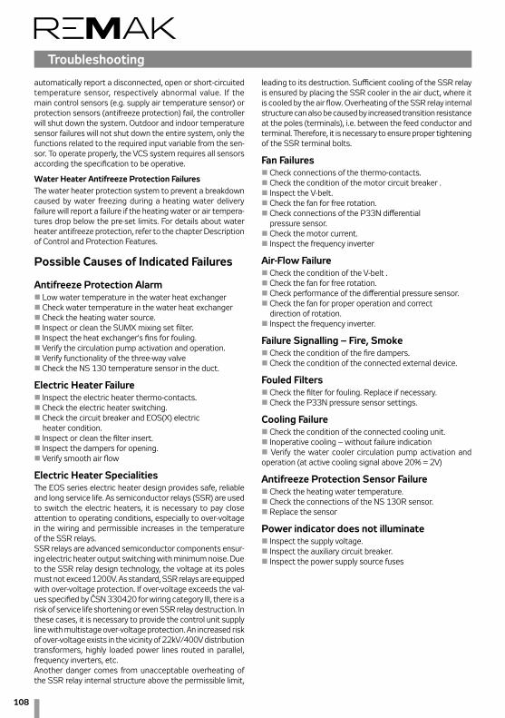
108
automatically report a disconnected, open or short-circuited temperature sensor, respectively abnormal value. If the main control sensors (e.g. supply air temperature sensor) or protection sensors (antifreeze protection) fail, the controller will shut down the system. Outdoor and indoor temperature sensor failures will not shut down the entire system, only the functions related to the required input variable from the sen-sor. To operate properly, the VCS system requires all sensors according the specification to be operative.
Water Heater Antifreeze Protection Failures The water heater protection system to prevent a breakdown caused by water freezing during a heating water delivery failure will report a failure if the heating water or air tempera-tures drop below the pre-set limits. For details about water heater antifreeze protection, refer to the chapter Description of Control and Protection Features.
Possible Causes of Indicated Failures
Antifreeze Protection Alarmn Low water temperature in the water heat exchangern Check water temperature in the water heat exchangern Check the heating water source.n Inspect or clean the SUMX mixing set filter.n Inspect the heat exchanger's fins for fouling.n Verify the circulation pump activation and operation.n Verify functionality of the three-way valve n Check the NS 130 temperature sensor in the duct.
Electric Heater Failuren Inspect the electric heater thermo-contacts.n Check the electric heater switching.n Check the circuit breaker and EOS(X) electric heater condition.n Inspect or clean the filter insert.n Inspect the dampers for opening.n Verify smooth air flow
Electric Heater SpecialitiesThe EOS series electric heater design provides safe, reliable and long service life. As semiconductor relays (SSR) are used to switch the electric heaters, it is necessary to pay close attention to operating conditions, especially to over-voltage in the wiring and permissible increases in the temperature of the SSR relays.SSR relays are advanced semiconductor components ensur-ing electric heater output switching with minimum noise. Due to the SSR relay design technology, the voltage at its poles must not exceed 1200V. As standard, SSR relays are equipped with over-voltage protection. If over-voltage exceeds the val-ues specified by ČSN 330420 for wiring category III, there is a risk of service life shortening or even SSR relay destruction. In these cases, it is necessary to provide the control unit supply line with multistage over-voltage protection. An increased risk of over-voltage exists in the vicinity of 22kV/400V distribution transformers, highly loaded power lines routed in parallel, frequency inverters, etc.Another danger comes from unacceptable overheating of the SSR relay internal structure above the permissible limit,
leading to its destruction. Sufficient cooling of the SSR relay is ensured by placing the SSR cooler in the air duct, where it is cooled by the air flow. Overheating of the SSR relay internal structure can also be caused by increased transition resistance at the poles (terminals), i.e. between the feed conductor and terminal. Therefore, it is necessary to ensure proper tightening of the SSR terminal bolts.
Fan Failuresn Check connections of the thermo-contacts.n Check the condition of the motor circuit breaker .n Inspect the V-belt.n Check the fan for free rotation.n Check connections of the P33N differential pressure sensor.n Check the motor current.n Inspect the frequency inverter
Air-Flow Failuren Check the condition of the V-belt .n Check the fan for free rotation.n Check performance of the differential pressure sensor.n Check the fan for proper operation and correct direction of rotation.n Inspect the frequency inverter.
Failure Signalling – Fire, Smoken Check the condition of the fire dampers.n Check the condition of the connected external device.
Fouled Filters n Check the filter for fouling. Replace if necessary.n Check the P33N pressure sensor settings.
Cooling Failuren Check the condition of the connected cooling unit.n Inoperative cooling – without failure indicationn Verify the water cooler circulation pump activation and operation (at active cooling signal above 20% = 2V)
Antifreeze Protection Sensor Failure n Check the heating water temperature.n Check the connections of the NS 130R sensor.n Replace the sensor
Power indicator does not illuminate n Inspect the supply voltage.n Inspect the auxiliary circuit breaker.n Inspect the power supply source fuses
Troubleshooting

109
Control units VCS
TroubleshootingWhen performing any handling or troubleshooting of the air-handling device, the power supply of the entire distribution board must be disconnected using the main switch. When performing inspections, pay increased attention to the correct functioning of the protection devices (SUMX mixing set, motor thermo-contacts and electric heater thermo-contacts). Verify the correct functioning of evaluating, protection and switch-ing devices. Check the control signal. Check the terminals for proper tightening, both on the peripheral device side and control unit side.
Regular InspectionsService inspections of the entire air-handling system must be performed at least twice a year (unit transition from winter to summer operating mode).In addition to these, extra inspections must also be performed after a unit failure, natural disaster or emergencies.Maintenance of the control unit includes just regular cleaning and inspection of the screw connections – wires, grounding, component fixing, etc. Internal parts of the unit must be cleaned of dust and any other dirt at the specified mainte-nance intervals. If necessary, clean the face panel of the unit's box using a wet cloth. Use common cleaners.When changing over to the summer operating mode, drain the heating water circuit; the mixing set pump must be discon-nected. To do so, turn the disconnector to the "Off" position. (Otherwise, ensure regular turning of the pump to prevent the pump seizing; operating the pump without water can damage it). In the winter operating mode, the pump must be activated using the reverse order of steps, i.e. turned "On" and checked for proper operation. The same procedure must be performed when the water cooler is being shut down for a season or reactivated. (Note that the water cooler pump does not turn the system).
Spare Parts and ServiceSpare parts are not included in the VCS unit delivery. If any spare parts are needed, they can be ordered from the manufacturer or regional distributor. Warrantee and regular servicing can be ordered from the manufacturer or the authorized service provider (see the list on www.remak.eu).
Spare Parts and Service
Disposal and RecyclingWhen using or disposing of the air-handling unit, it is necessary to observe the respective national environmental protection and waste disposal regulations. In case of final unit liquida-tion, it is necessary to follow the policy of sorted waste dis-posal; this means respecting differences in materials and their composition. It is necessary to hire a provider specialized in sorted waste disposal in accordance with the applicable local standards and regulations. Active carbon which contains toxic substances, radioactive impurities or PCB must be disposed of in accordance with applicable legal regulations. After exceed-ing its service life limit, the unit belongs to waste group Q14 according to the Waste Act (No.185/2001 Coll.).
AbbreviationsBPDEV ..................Plate Heat Exchanger BypassTČ ............................Heat PumpTK ............................ThermocontactPMO .......................Antifreeze ProtectionROV ........................Rotary Heat ExchangerVZT .........................Air-handling DeviceZZT .........................Heat RecoveryFTT-10A ...............Free Topology Transceiver for channel type TP/FT-10 (LON)TP/FT-10 .............Physical channel to transmit data over Twisted Pair to Free Topology networksSNVT .....................Standard Network Variable Type (LON)LON ........................Local Operating NetworkSCADA ..................Supervisory control and data acquisitionBMS .......................Building Management SystemModBus RTU .....Communication protocol (Remote Terminal Unit) Climatix ................A series of controllers providing the same featuresAHU .......................Air Handling Unit SELV ......................Safety Extra-Low VoltageHMI .........................HumanMachineInterface – remote controllerBACnet .................Building Automation and Control NetworkTCP/IP ..................Transmission Control Protocol, např.. Ethernet/Internet
Waste Classification (in accordance with Directive No. 381/2001 Sb.)
Materials used to pack the product: n 15 01 01 cardboard box (paper and cardboard packaging)n 15 01 02 polyester packaging pads (plastic packaging)n 15 01 03 pallet (wooden packaging products)
Disabled device and its parts:n 13 02 06 Waste engine, transmission and lubricating oils (synthetic engine, transmission and lubricating oils)n 16 02 06 metal and aluminium parts insulating material (other items from disposed devices)n 15 02 03 filtering materialsn 16 02 15 electrical parts (dangerous items from disabled devices)


Always observe local laws and regulations
LonLink™, LON® / LonManager®, LonMark®, LonTalk®, LonWorks®, Neuron® are registered trade marks of Echelon Corporation. Modbus® is registered trade mark of The Modbus Organization.BACnet® is registered trade mark of American National Standard Corporation.
Printing and language mistakes are reserved.These Installation and Operating Instructions (as a whole or a part) must not be printed or copied without prior written permission from REMAK a. s., Zuberská 2601, Rožnov pod Radhoštěm, Czech RepublicThese Installation and Operating Instructions are the sole property of REMAK a. s.Changes reserved. Issued: 12. 12. 2014
WarningThe manufacturer reserves the right to make changes and amend the documentation due to technical innovations and changes to legislation without prior notice.
REMAK a.s.Zuberská 2601, 756 61 Rožnov pod Radhoštěm,tel.: +420 571 877 778, fax: +420 571 877 777,email: [email protected], internet: www.remak.eu
55R
0807
0435