Control Systems of a Non-stationary Plant Based on … automatic control system with MPC controller...
6
Abstract— Typically, processes taking place in modern industrial plants have significant nonlinearity. To control so complex dynamic processes used automatic control system (ACS) based on fuzzy logic controllers (FLC) or on the basis of a predictive model controllers (MPC). In this paper are compared the systems of automatic control with different regulators (fuzzy PID regulator and MPC regulator), if introduced into the system of different disturbing influences. Index Terms—model predictive control, fuzzy logic controller, PID controller, control system. I. INTRODUCTION urrently in the industry, at any stage of processing of the material / substance there is a high level of automation. The use of automatic control systems of production processes is done in order to improve the safety of the technological process, as well as improve the economic performance of plants and production as a whole. As a rule, the majority of technological processes (plants), occurring today in the industry, is a complex dynamic objects. Complex dynamic systems are objects with nonlinear static characteristics, that is, objects that are described by differential equations with time-varying parameters. Experience has shown that control of such plants by means of traditional PID controllers does not provide the required quality control. In order to improve the efficiency of automatic control system of complex dynamic objects, researchers around the world, doing research, trying to combine the standard PID regulator with fuzzy adaptive controller [1, 2]. Currently, Manuscript received December 6, 2015; revised January 22, 2016. This work was funded as part of the Federal government-sponsored program «Science» by Tomsk Polytechnic University. I. S. Nadezhdin is with the National Research Tomsk Polytechnic University, Institute of Physics and Technology, Department of Electronics and Automation of Nuclear Plants, Russia, Tomsk, Lenina St 30, 634050 (corresponding author to provide phone: +7-923-423-68-85; e-mail: [email protected]). A. G. Goryunov is with the National Research Tomsk Polytechnic University, Institute of Physics and Technology, Department of Electronics and Automation of Nuclear Plants, Russia, Tomsk, Lenina St 30, 634050 (e-mail: [email protected]). F. Manenti is with the Politecnico di Milano, Dept. di Chimica, Materiali e Ingegneria Chimica “Giulio Natta”, Italy, Milano, Piazza Leonardo da Vinci, 32, 20133 (e-mail: [email protected]). A. O. Ochoa Bike is with the National Research Tomsk Polytechnic University, Institute of Physics and Technology, Department of Electronics and Automation of Nuclear Plants, Russia, Tomsk, Lenina St 30, 634050 (e-mail: [email protected]). there are different types of fuzzy controllers, but the fuzzy controller based PID regulators are the most common [3, 4]. As a rule, setting a fuzzy controller is made based on the Mamdani controller. In this, the controller Mamdani is located directly in the control channel, as shown in the papers [5, 6]. For this research using fuzzy PID regulator presented in this paper [7], but without the procedure of identification of parameters of the control plant. The distinguishing feature of this fuzzy PID controller is that in him using expert grade determined coefficients PID regulator. Also, recently, for the control of complex dynamic objects are widely used controllers on the basis of a predictive model [8, 10]. For the synthesis of such a regulator is necessary to make a mathematical model of the control plant. Using a mathematical model of the control plant, regulator is to predict changes in the controlled variable for a certain period of time ahead and calculate the optimal control action, to provide the best trajectory of the controlled variable. The purpose of this paper is the comparative analysis of automatic control systems with PID regulator based on fuzzy logic and regulator on the basis of a predictive model (MPC- controller). In this case system will be introduced stepwise disturbing influences are not known magnitude and duration. II. THEORETICAL PART A. Control plant Since in the paper discussed automatic control system for a complex dynamic control plant, the parameters of such an plant can be changed during the process. At the initial time control plant is described by the transfer function of the first order (1). The dynamics of the control plant is described as a linear system with the transfer function Wp u (s) that represents channel u and the transfer function Wp f (s)that stand for channel f: () , 1 () 1 p f p s p u p p f s p f p f p k W s e T s k W s e T s (1) In current of process, when switching plant from one mode to another or when changing characteristics of the Control Systems of a Non-stationary Plant Based on MPC and PID Type Fuzzy Logic Controller Igor S. Nadezhdin, Aleksey G. Goryunov, Flavio Manenti, Anton O. Ochoa Bike C Proceedings of the International MultiConference of Engineers and Computer Scientists 2016 Vol I, IMECS 2016, March 16 - 18, 2016, Hong Kong ISBN: 978-988-19253-8-1 ISSN: 2078-0958 (Print); ISSN: 2078-0966 (Online) IMECS 2016
Transcript of Control Systems of a Non-stationary Plant Based on … automatic control system with MPC controller...
Abstract— Typically, processes taking place in modern
industrial plants have significant nonlinearity. To control so
complex dynamic processes used automatic control system
(ACS) based on fuzzy logic controllers (FLC) or on the basis of
a predictive model controllers (MPC). In this paper are
compared the systems of automatic control with different
regulators (fuzzy PID regulator and MPC regulator), if
introduced into the system of different disturbing influences.
Index Terms—model predictive control, fuzzy logic
controller, PID controller, control system.
I. INTRODUCTION
urrently in the industry, at any stage of processing of the
material / substance there is a high level of automation.
The use of automatic control systems of production
processes is done in order to improve the safety of the
technological process, as well as improve the economic
performance of plants and production as a whole. As a rule,
the majority of technological processes (plants), occurring
today in the industry, is a complex dynamic objects.
Complex dynamic systems are objects with nonlinear static
characteristics, that is, objects that are described by
differential equations with time-varying parameters.
Experience has shown that control of such plants by means
of traditional PID controllers does not provide the required
quality control.
In order to improve the efficiency of automatic control
system of complex dynamic objects, researchers around the
world, doing research, trying to combine the standard PID
regulator with fuzzy adaptive controller [1, 2]. Currently,
Manuscript received December 6, 2015; revised January 22, 2016. This
work was funded as part of the Federal government-sponsored program
«Science» by Tomsk Polytechnic University.
I. S. Nadezhdin is with the National Research Tomsk Polytechnic
University, Institute of Physics and Technology, Department of Electronics
and Automation of Nuclear Plants, Russia, Tomsk, Lenina St 30, 634050
(corresponding author to provide phone: +7-923-423-68-85; e-mail:
A. G. Goryunov is with the National Research Tomsk Polytechnic
University, Institute of Physics and Technology, Department of Electronics
and Automation of Nuclear Plants, Russia, Tomsk, Lenina St 30, 634050
(e-mail: [email protected]).
F. Manenti is with the Politecnico di Milano, Dept. di Chimica,
Materiali e Ingegneria Chimica “Giulio Natta”, Italy, Milano, Piazza
Leonardo da Vinci, 32, 20133 (e-mail: [email protected]).
A. O. Ochoa Bike is with the National Research Tomsk Polytechnic
University, Institute of Physics and Technology, Department of Electronics
and Automation of Nuclear Plants, Russia, Tomsk, Lenina St 30, 634050
(e-mail: [email protected]).
there are different types of fuzzy controllers, but the fuzzy
controller based PID regulators are the most common [3, 4].
As a rule, setting a fuzzy controller is made based on the
Mamdani controller. In this, the controller Mamdani is
located directly in the control channel, as shown in the
papers [5, 6]. For this research using fuzzy PID regulator
presented in this paper [7], but without the procedure of
identification of parameters of the control plant. The
distinguishing feature of this fuzzy PID controller is that in
him using expert grade determined coefficients PID
regulator.
Also, recently, for the control of complex dynamic objects
are widely used controllers on the basis of a predictive
model [8, 10]. For the synthesis of such a regulator is
necessary to make a mathematical model of the control
plant. Using a mathematical model of the control plant,
regulator is to predict changes in the controlled variable for
a certain period of time ahead and calculate the optimal
control action, to provide the best trajectory of the
controlled variable.
The purpose of this paper is the comparative analysis of
automatic control systems with PID regulator based on fuzzy
logic and regulator on the basis of a predictive model (MPC-
controller). In this case system will be introduced stepwise
disturbing influences are not known magnitude and duration.
II. THEORETICAL PART
A. Control plant
Since in the paper discussed automatic control system for
a complex dynamic control plant, the parameters of such an
plant can be changed during the process.
At the initial time control plant is described by the transfer
function of the first order (1). The dynamics of the control
plant is described as a linear system with the transfer
function Wpu(s) that represents channel u and the transfer
function Wpf(s)that stand for channel f:
( ) ,1
( )1
p
fp
spu
p
p
f
spf
p f
p
kW s e
T s
kW s e
T s
(1)
In current of process, when switching plant from one
mode to another or when changing characteristics of the
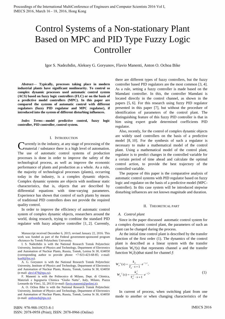
Control Systems of a Non-stationary Plant
Based on MPC and PID Type Fuzzy Logic
Controller
Igor S. Nadezhdin, Aleksey G. Goryunov, Flavio Manenti, Anton O. Ochoa Bike
C
Proceedings of the International MultiConference of Engineers and Computer Scientists 2016 Vol I, IMECS 2016, March 16 - 18, 2016, Hong Kong
ISBN: 978-988-19253-8-1 ISSN: 2078-0958 (Print); ISSN: 2078-0966 (Online)
IMECS 2016

material (feedstock) may vary the order of the transfer
function, which describes the control object on the control
channel Wpu(s). In our case the dynamics of the control plant
is described by the following transfer functions:
1 2 3
( ) ,1 1 1
( )1
p
fp
spu
p
p p p
f
spf
p f
p
kW s e
T s T s T s
kW s e
T s
(2)
In addition to changing the parameters of the control plant
in current of technological process in the system introduced
stepwise disturbing influences of unknown magnitude and
duration.
B. The automatic control system with adaptive fuzzy PID
controller
A proposed automatic control system with fuzzy PID
controller is shown in Figure 1.
Depicted in Figure 1 the variables have the following
meanings: g – set point; f – measurable disturbance; u –
control action; Pu – plant control channel; Pf – plant
disturbance channel; y – controlled variable; – control
error is defined as = g – y.
Let us consider in more detail the adaptive fuzzy
regulator, presented in Figure 1. Scheme adaptive fuzzy
controller is shown in Figure 2.
Adaptive fuzzy regulator consists of the following blocks:
a fuzzy rules base generator, a Mamdani fuzzy output
controller and Jn, Je and Ju terms calculation engines.
The optimization problem consists of maximizing or
minimizing a functional which plays the key role from the
viewpoint of the design of adaptive and optimal control
systems. It is addressed here in the following form:
min k k kJe Ju Jn (3)
where
2
1
k he
j
j k
kJehe
(4)
2
1
k hu
j k
j k
k
u u
Juhu
(5)
kJn – the number of control error oscillations in the interval
he, (4).
where k = 1,2,…, j – the control error, uj – the control
action, he – the control error interval, hu – the control
interval, j – the index of time sampling.
For the calculation of parameters of the PID regulator is
used controller Mamdani with fuzzy rules, obtained by
minimizing the functional (3).
C. The automatic control system with MPC controller
The automatic control system with MPC controller is
similar automatic control system with adaptive fuzzy
controller (Figure 3).
Structural sheme of MPC controller is shown in Figure 4.
The structure of the regulator includes: a predictive model
and power optimization.
Main idea of model predictive control can be represented
Control plant
Pf
PuAdaptive fuzzy
controller
f
y
ug ε
Fig. 1. Adaptive fuzzy automatic control system
Fuzzy rules base
generator
Jn
PID controller
Je
Ju
kp,Tp, tp
kr,Ti, Td
ε u
Adaptor-optimizer
Fig. 2. Adaptive fuzzy controller
Control plant
Pf
PuМРС controller
f
y
ug ε
Fig. 3. The automatic control system with MPC controller
Block
optimization
Predictive model
(a process model)
Predictive controller
ε u
y*
Fig. 4. Structural scheme of MPC controller
Proceedings of the International MultiConference of Engineers and Computer Scientists 2016 Vol I, IMECS 2016, March 16 - 18, 2016, Hong Kong
ISBN: 978-988-19253-8-1 ISSN: 2078-0958 (Print); ISSN: 2078-0966 (Online)
IMECS 2016

following manner: there are control action u(t) and y(t)
controlled variable, g(t) is the desired value (dependence)
changes in the controlled variable. Consider a system in
discrete time, it is only in moments of time t=k·ΔT, where
ΔT – some sampling period, and k – some integer. For
convenience the graphical representation we will consider
ΔT=1.
The main feature of model predictive control is a
mathematical model of the control plant, which accurately
describes its behavior. Availability of an adequate
mathematical model of control plant allows to predict the
value of the controlled variable to a certain number of steps
forward (Figure 5).
The values of the controlled variable y(t), predicted at
some time t, in Figure 5 are designated following manner
( )y t
. Horizon prediction is built on a certain number of
clock cycles. The projected trajectory of the controlled
variable will depend on the future values of the control
action u(t).
Essence of method consists in finding a sequence of
values of the control action u(t), which will provide the best
projected trajectories for the controlled variable y(t). The
sequence length of the calculated control actions u(t) is a
fixed quantity and is called the horizon control. The
sequence of values of the control action is determined by
solving a problem of optimization. Choosing the best
trajectory the controlled variable is determined by indicators
of quality control.
The paper is used the quality indicators, which contains
the square error between the predicted controlled variable
control plant y(t) and the desired trajectory (set point) g(t).
When choosing the optimal values of the control action u(t),
regulator seeks to minimize the functional submitted by
expression of the form:
1
2 2
1 0
p m
i i
J Q y k i r k i R u k i
(6)
where: Q and R – weighting coefficients, p – the number of
cycles on which build the prediction of the behavior of the
controlled variable y(t) (prediction horizon), m – the length
of the sequence of future values of the control action u(t)
(horizon control).
After feeding by at control plant of the first element
calculated the optimal sequence the control action u(t), at the
next clock cycle the whole procedure is repeated again,
taking into account the the newly received information.
So is functioning regulator with a predictive model.
III. RESULTS OF EXPERIMENTAL RESEARCH
Described before automatic control system with different
controllers have been implemented in MATLAB/Simulink.
To configure fuzzy PID regulator in automatic control
systems (Figure 1) have been defined parameters control
plant described by the transfer function of the first order (1).
For the synthesis of regulator with model predictive is
used the transfer function of the first order (1), with the same
parameters as for setting fuzzy PID regulator.
In both automatic control systems impose restrictions on
the control action.
At a certain moment in time has been set a desired value
for the controlled variable (setpoint). The resulting setpoint
the transient processes shown in Figure 6.
As can be seen from of transient processes (Figure 6),
both the automatic control systems derive controlled
variable to a predetermined level. Time control of the
automatic control system with fuzzy PID controller totaled
0,036 hours (128.9 seconds), but with the MPC-controller
0.0094 hour (34 seconds). Overshoot automatic control
system with fuzzy PID was 7.8 %, and the control system
with MPC-controller came out on a predetermined level
without overshoot. Also for of transient processes presented
in Figure 6 it was calculated quadratic integral criterion
(QIC) from the following expression:
2
1
2( ) ( )
t
t
QIC g t y t dt (7)
The past
Currently
Future
t
t
g(t)
y(t)
u(t)
Horizon control
Horizon prediction
( )y t
Fig. 5. A graphical representation of the idea of model predictive control
Fig. 6. The transient processes for set point
Proceedings of the International MultiConference of Engineers and Computer Scientists 2016 Vol I, IMECS 2016, March 16 - 18, 2016, Hong Kong
ISBN: 978-988-19253-8-1 ISSN: 2078-0958 (Print); ISSN: 2078-0966 (Online)
IMECS 2016
Calculation results are shown in Table 1.
After analyzing the quality indicators can be seen that best
the transition process for set point system automatic control
with MPC controller provides.
Then, at time 0.14 hours, the system been introduced 30%
stepwise disturbance. The obtained the transient processes
are presented in Figure 7.
For of transient processes (Figure 7) were identified
quality indicators of transient processes automatic control
system for the disturbing influence.
Time control of automatic control system with fuzzy PID
controller was 0.0275 hours (99 seconds), and with MPC
regulator 0.0318 hour (114.48 seconds). To estimate the
maximum deviation of the controlled variable from the
steady-state value calculated relative maximum deviation
using the following expression:
max 100[%]y
g (8)
where ymax – the maximum deviation of the controlled
variable, g – setpoint for the controlled variable.
Calculation results are shown in Table 2. Also for of
transient processes presented in Figure 6 it was calculated
quadratic integral criterion (QIC) using the expression (7).
Analyzing the obtained values of the indicators quality of
transient processes can be concluded that the fuzzy PID
controller is a little better compensate the disturbance.
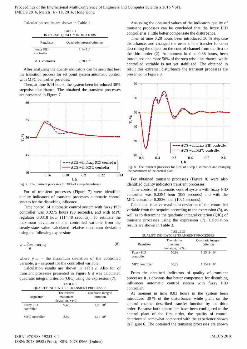
Then at time 0.28 hours been introduced 50 % stepwise
disturbance, and changed the order of the transfer function
describing the object on the control channel from the first to
the third order (2). At moment in time 0.38 hours, been
introduced one more 50% of the step wise disturbance, while
controlled variable is not yet stabilized. The obtained in
result this extremal disturbance the transient processes are
presented in Figure 8.
For obtained transient processes (Figure 8) were also
identified quality indicators transient processes.
Time control of automatic control system with fuzzy PID
controller was 0.2384 hour (858 seconds) and with the
MPC-controller 0.2836 hour (1021 seconds).
Calculated relative maximum deviation of the controlled
variable from the setpoint according to the expression (8), as
well as to determine the quadratic integral criterion (QIC) of
transient processes using the expression (7). Calculation
results are shown in Table 3.
From the obtained indicators of quality of transient
processes it is obvious that better compensate for disturbing
influences automatic control system with fuzzy PID
controller.
At moment in time 0.83 hours in the system been
introduced 30 % of the disturbance, while plant on the
control channel described transfer function by the third
order. Because both controllers have been configured to the
control plant of the first order, the quality of control
deteriorated somewhat compared with the experience shown
in Figure 6. The obtained the transient processes are shown
TABLE II
QUALITY INDICATORS TRANSIENT PROCESSES
Regulator
The relative
maximum
deviation, σ (%)
Quadratic integral
criterion
Fuzzy PID
controller
9,48 1,09·103
МРС controller 8,92 1,16·103
TABLE I
INTEGRAL QUALITY INDICATORS
Regulator Quadratic integral criterion
Fuzzy PID
controller
1,14·105
МРС controller 7,78·104
Fig. 8. The transient processes for 50% of a step disturbance and changing
the parameters of the control plant
TABLE III
QUALITY INDICATORS TRANSIENT PROCESSES
Regulator
The relative
maximum
deviation, σ (%)
Quadratic integral
criterion
Fuzzy PID
controller
50,68 1,1543·105
МРС controller 50,22 1,1571·105
Fig. 7. The transient processes for 30% of a step disturbance
Proceedings of the International MultiConference of Engineers and Computer Scientists 2016 Vol I, IMECS 2016, March 16 - 18, 2016, Hong Kong
ISBN: 978-988-19253-8-1 ISSN: 2078-0958 (Print); ISSN: 2078-0966 (Online)
IMECS 2016

in Figure 9.
As seen in Figure 9, obtained the transient processes
characterized by the presence of oscillations of the
controlled variable. For represented of the transient
processes determine the direct indicators of quality.
Time control of automatic control system with fuzzy PID
controller was 0.1957 hour (704 seconds) and with the MPC
controller was 0.1053 hour (379 seconds).
Similar to previous experiments, calculated relative to the
maximum deviation of the controlled variable from the set
point using the expression (8), as well as to determine the
quadratic integral criterion (QIC) of transient processes
using the following expression (7).
Furthermore, in order to evaluate the oscillatory transient
processes was calculated degree of damping vibrations
according to the following expression:
1 2
1
А A
А
(9)
where: А1 and А2 – amplitude two adjacent vibrations
directed in the same direction.
Calculation results are shown in Table 4.
The calculated quality indicators of transient processes
(Figure 9) numerically confirm that the automatic control
system with the MPC controller has a much better quality
control.
IV. DISCUSSION OF THE RESULTS
Comparing the transient processes shown in Figures 5-8
and analyzing quality indicators calculated for these of
transient processes define the controller that provides the
best quality control.
In the derivation of the controlled variable to a
predetermined level the best indicators quality of transient
processes provides the control system with MPC controller.
When using the MPC controller is no overshoot of the
controlled variable (Figure 5), and the time regulation is 3.8
times less than using fuzzy PID controller.
However, when in a system occurs 30% of stepwise
disturbance the transient processes were obtained (Figure 7)
which show that time regulation of fuzzy PID regulator in
1.15 times less than using the MPC controller, as well as the
quadratic integral criterion is 1.1 times less. But a relative
maximum deviation when using the fuzzy PID regulator
more is 1.1 times. As can be seen, the control system with
the fuzzy PID controller provides the transient processes
with the best quality indicators.
Then, in the system been introduced 50% of the
disturbance, and change the parameters of the control plant
and the order of the transfer function, which describes the
plant on the control channel with first order for a third (2).
According to the obtained the transition process (Figure 8)
determined that the control system with the fuzzy PID
controller provides is 1.2 times less time regulation, but has
by 0.5 % more relative maximum deviation. Quadratic
integral criteria calculated for of transient processes (Figure
8) are presented in Table 3, and they do not differ
significantly. In this case, the control system with fuzzy PID
controller slightly better fulfills disturbing influences.
Then for control plant with new parameters of been
introduced 30% of the disturbance. From the presented in
Figure 9 of transient processes determined that the control
system with the MPC controller provides the best quality
indicators (Table 4). Time regulation control system with
MPC controller is 1.86 times less than that the control
system with the fuzzy PID controller. As well as a relative
maximum deviation is 1.02 times less and quadratic integral
criterion is 1.37 times less. In addition, the MPC controller
provides is 1.5 times higher degree of damping of
oscillations controlled variable than the fuzzy PID
controller.
Thus, by comparing and analyzing the results obtained
when modeling of automatic control system with two
different controllers (fuzzy PID controller and MPC
controller), can not be selected any single.
Separately, let us note advantages and disadvantages of
the used controllers.
The advantages of the considered fuzzy PID regulator is
the possibility its realization using standard industrial
components. For this requires a PID controller and industrial
controller, in which DLL library will be implemented
adapter optimizer.
The need to in accurate and adequate mathematical
models of the control plant is possible to carry to the
disadvantages of the MPC controller. The first is not always
possible to make an adequate mathematical model of the
TABLE IV
QUALITY INDICATORS TRANSIENT PROCESSES
Regulator
Fuzzy PID
controller
МРС controller
The relative
maximum
deviation, σ (%)
16,62 16,26
Quadratic integral
criterion
1,2569·104 9,4949·103
The extent of
damping, ψ
0,48 0,72
Fig. 9. The transient processes for 30% of a step disturbance and the new
parameters of control plant
Proceedings of the International MultiConference of Engineers and Computer Scientists 2016 Vol I, IMECS 2016, March 16 - 18, 2016, Hong Kong
ISBN: 978-988-19253-8-1 ISSN: 2078-0958 (Print); ISSN: 2078-0966 (Online)
IMECS 2016

control plant and secondly, than more complex mathematical
model of control plant, the more computing power is
required to implement the MPC controller.
V. CONCLUSION
This paper devoted to the synthesis and comparison of
automatic control systems with fuzzy PID controller with
MPC controller. When comparing the quality indicators
obtained transient processes, failed to make an unambiguous
choice in favor of one of the comparable regulators. Noted
advantages and disadvantages the considered regulators.
ACKNOWLEDGMENT
This work was funded as part of the Federal government-
sponsored program «Science» by Tomsk Polytechnic
University.
REFERENCES
[1] M. Guzelkaya, I. Eksin, E. Yesil, “Self-tuning of PID-type fuzzy logic
controller coefficients via relative rate observer,” Engineering
Applications of Artificial Intelligence, Vol. 16, pp.227–236, 2003.
[2] N. Siddique, “Fuzzy control,” Studies in Computational Intelligence,
Vol. 517, pp. 95-135, 2014.
[3] A. Fereidouni, M.A.S. Masoum, M. Moghbel, “A new adaptive
configuration of PID type fuzzy logic controller,” ISA Transactions,
Vol. 56, pp. 222-240, 2015.
[4] L. Y. Ang, F. A. Jafar, “Simulation analysis of non-linear fuzzy PID
temperature controller,” Applied Mechanics and Materials, Vol. 465-
466, pp. 677-681, 2014.
[5] I. Eker, Y. Torun, “Fuzzy logic control to be conventional method,”
Energy Conversion and Management, Vol. 47, pp. 377–394, 2006.
[6] I. Pana, S. Dasa, A. Gupta, “Tuning of an optimal fuzzy PID
controller with stochastic algorithms for networked control systems
with random time delay,” ISA Transactions, Vol. 50, pp. 28–36,
2011.
[7] F. Manenti, F. Rossi, A. G. Goryunov, V. F. Dyadik, K. A. Kozin,
I. S. Nadezhdin, S. S. Mikhalevich, “Fuzzy adaptive control system of
a non-stationary plant with closed-loop passive identifier,” Resource-
Efficient Technologies, vol. 1, pp. 10–18, Jul. 2015.
[8] F. Manenti, “Considerations on nonlinear model predictive control
techniques,” Computers and Chemical Engineering, vol. 35, 2491–
509, 2011.
[9] D. Jolevski, O. Bego, “Model predictive control of gantry/bridge
crane with anti-sway algorithm,” Journal of Mechanical Science and
Technology, vol. 29, pp. 827-834, 2015.
[10] M. Nayhouse, A. Tran, J.S.I. Kwon, M. Crose, G. Orkoulas,
P.D. Christofides, “Modeling and control of ibuprofen crystal growth
and size distribution,” Chemical Engineering Science, vol. 134, pp.
414-422, 2015.
Proceedings of the International MultiConference of Engineers and Computer Scientists 2016 Vol I, IMECS 2016, March 16 - 18, 2016, Hong Kong
ISBN: 978-988-19253-8-1 ISSN: 2078-0958 (Print); ISSN: 2078-0966 (Online)
IMECS 2016