
Control System Lecture 2006
23
2.007 Control System Hong Ma Wey-Jiun Lin Spring 2006
description
Control System Lecture 2006
Transcript of Control System Lecture 2006

2.007 Control SystemHong Ma
Wey-Jiun LinSpring 2006

Control System Overview
Radio Link
Your Robot

Control BoxKey Features
Motor On/Off Button
Power Plug
Motor Plug
Mass:Approx. 0.39 kg (0.85 lbs.)
Box Color
Vents
Autonomous Connector

Control BoxElectrical Characteristics
• 4 channel output• Up to 3A maximum on each channel
Motor Connector

Control Box FeatureIndicators
Motor Status Indicators
Status IndicatorsPower LED

Control Box Feature:Battery Low-voltage Protection
• Red LED turns on when the battery is low.
• Motor controllers will turns off automatically soon after that.

Control Box Feature:Thermal Protection
• Amber Thermal Warning LED turns on when the internal temperature of the motor controller is too high.
• Thermal Warning usually means that your motor has been stalled for >35s. Beware of damage to your motor!
• Turn off motors, but leave the control box plugged in for cooling.
• Continued heating will cause automatic shutoff.

Control SystemPodium
ThrottlesInactiveButton
Red=Stop
Green=Forward
Blue=Reverse
This is the RED podium

The BatteryYour Robot’s Power Source• Beefy NiCd battery• 14.4V nominal, but actually 12-17V depending on charge
NegativePositive+ -
+
-
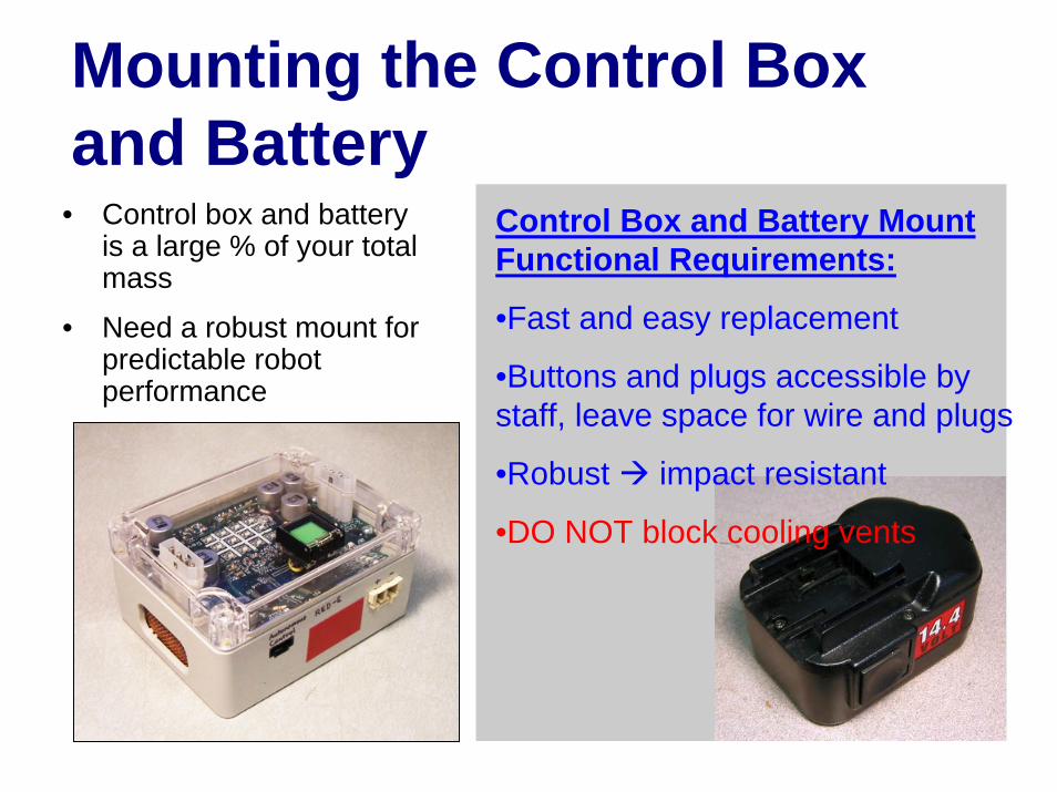
Mounting the Control Box and Battery
• Control box and battery is a large % of your total mass
• Need a robust mount for predictable robot performance
Control Box and Battery Mount Functional Requirements:
•Fast and easy replacement
•Buttons and plugs accessible by staff, leave space for wire and plugs
•Robust impact resistant
•DO NOT block cooling vents

“Good” Battery Mounting Example

The MotorYour Robot’s “Engines”• 6V motor designed for remote control cars• Torque-Speed characteristics available

Wiring Your Motor
NO EXPOSED CONTACTS•Electrical Tape•Heat Shrink Tubing
Can damage your machine and the control box.
Wiring will be checked on impound day.
BAD WIRING = YOU CANNOT COMPETE!!
Make a Loop with the Wire. Hold in place with a Zip Tie or thin strip of electrical tape.
DO NOT Block Cooling Vents!!!
Cover Electrical Contacts with Heat Shrink or Electrical Tape.
• Motor electrical contacts are extremely fragile. They must be strain-relieved.

How to Make a Battery PlugWhat You’ll Need
2 x 1/4” Tab Connectors
2 x Connector Terminals
2 x 18 AWGWire
1 x 2 Pos.Connector
4 x 3/16” Heat Shrink

HINT: Label the terminals to avoid plugging things backwards!!!
2: Tin
3: Solder 4: Crimp
1: Strip
6: Plug
How to Make a Battery PlugKey Steps
5: Shrink
+-

Using Your ConnectorsBattery to Control Box
+-+ -

How to Make the Motor PlugsWhat You’ll Need
4 x femaleTerminals
8 x 18 awgWire
2 x 4 Pos.Connectors
8 x 3/16” Heat Shrink

How to Make the Motor PlugsKey Steps
2: Tin
4: Crimp3: Solder
6: Plug
5: Shrink
1: Strip

Using Your ConnectorsMotors to Control Box
MOTOR 4
MOTOR 3
MOTOR 2
MOTOR 1

Using Your ConnectorsMotors to Control Box
1: Tape2: Test3: Solder

More Wiring TipsEE for MechE
Do:• Wrap all connections with
heat-shrink or electrical tape
• Strain relieve all connections. Zip ties, etc. are in the cabinet
• Keep your wires as short as possible
• If you need longer wires, twist/braid them together to reduce interference
Don’t:• Make connections solely
with electrical tape. Solder them or use a connector
• Wire your machine like a rat’s nest
• Allow your motor leads to short against each other
• Use wires as string• Wait until impounding day
to wire your machine

Tips and FAQ• Control box is on, but my motors doesn’t
work – Check the on button, check for stop from all 4 channels.
• I can’t get over obstacles – Rock back and forth, don’t stall your motors!
• I get spurious radio signals when I’m driving – Your motor wires are causing interference. Shorten your wires, twise/braid them together, and don’t encase your control box in metal

Appendix: How to Solder Wires Together1. Strip insulation
5. Give it the “pull test”.
3. Tin the exposed wire with solder (infuse the wire with solder)
4. Press the wires together with a soldering iron. Add more solder if necessary.
6. Shrink the Heat-shrink or cover with electrical tape.
2. Put on heat-shrink


![Lecture V: Learning for Control · 2006. 1. 26. · Lecture V: MLSC - Dr. Sethu Vijayakumar 10 Other Measures of Model Complexity VC Dimension [Vapnik-Chernovenkis] Provides a general](https://static.fdocuments.in/doc/165x107/6020421dd6d91022997b7e9d/lecture-v-learning-for-2006-1-26-lecture-v-mlsc-dr-sethu-vijayakumar-10.jpg)