Control System for the Prototype of Hydrogen Powered Car€¦ · · 2006-09-29Control System for...
5
Control System for the Prototype of Hydrogen Powered Car Jiri Koziorek 1 , Zdenek Slanina 2 1 Department of Measurement and Control 2 Centre of Applied Cybernetics VSB-Technical University of Ostrava 17.listopadu 15, 708 33, Ostrava-Poruba CZECH REPUBLIC http://hydrogenix.vsb.cz Abstract: The contribution describes design and construction of hydrogen powered car based on fuel cell technology and electrical DC-drive. The main focus is given to control system and human machine interface of the car. The practical solution of control system is described and the experiences with its operation are presented. The wireless communication system for connection the car and PC monitoring system is described. The contribution also brings the results of testing the car. Key-Words: Control system design, programmable controllers, fuel cells, hydrogen, human machine interface 1 Introduction A team of several specialists and students of Department of Measurement and Control, VSB-Technical University of Ostrava, Czech Republic have designed and realized a prototype of hydrogen powered car based on fuel cell technology and electrical DC drive. The project is called HydrogenIX [6] and the works and testing activities came through between October 2004 and May 2005. The motivations for the project were following: − There is The Laboratory of Fuel Cells at Department of Measurement and Control. The development of mentioned car is first application of fuel cell in mobile system at the laboratory. − Activation of the interest of students, Ph.D. students, specialists and public in renewable and alternative energy sources. − Enlarge cooperation between university and external subjects in the field of renewable and alternative energy sources and related technologies. − Involve students to design and development activities in interesting area and demonstrate the result of the project in a competition of economization of energy in mobile vehicles. The competition is called Shell Eco-Marathon. The Shell Eco-Marathon is a competition organized by Shell Company and take place at race circuit in Nogaro, France. Teams of whole Europe try to reach highest distance with 1 litre of petrol, in the other words to have lowest consumption of the fuel. Even if the majority of teams use petrol engines in their vehicles, there are also vehicles powered by diesel, LPG, hydrogen and other alternative energies. The results are obtained by recalculating using calorific value of each type of fuel. So that it is possible to compare different types of fuel. A photo of the HydrogenIX car is at figure 1. Fig. 1 : HydrogenIX at Nogaro race circuit 2 Design of Control System The vehicle powered by hydrogen fuel cell needs electronic a control system assuring operation of its different parts. The complex electronic control is necessary already for basic operation of the vehicle, because there is a lot of subsystems that have to be coordinated and controlled. The control system assures especially following tasks: − Control of fuel cell operation – hydrogen input valve control, combustion products output valve control, fuel cell fan control, coupling produced electrical energy to electric DC-drive system. − Control of DC-drive system – motor current control, speed control. − Processing security tasks – assuring safe operation of fuel cell system and drive system, processing of hydrogen detector information, temperature measuring. 2005 WSEAS Int. Conf. on DYNAMICAL SYSTEMS and CONTROL, Venice, Italy, November 2-4, 2005 (pp369-373)
Transcript of Control System for the Prototype of Hydrogen Powered Car€¦ · · 2006-09-29Control System for...
Control System for the Prototype of Hydrogen Powered Car
Jiri Koziorek1, Zdenek Slanina2 1Department of Measurement and Control
2Centre of Applied Cybernetics VSB-Technical University of Ostrava
17.listopadu 15, 708 33, Ostrava-Poruba CZECH REPUBLIC
http://hydrogenix.vsb.cz
Abstract: The contribution describes design and construction of hydrogen powered car based on fuel cell technology and electrical DC-drive. The main focus is given to control system and human machine interface of the car. The practical solution of control system is described and the experiences with its operation are presented. The wireless communication system for connection the car and PC monitoring system is described. The contribution also brings the results of testing the car. Key-Words: Control system design, programmable controllers, fuel cells, hydrogen, human machine interface 1 Introduction A team of several specialists and students of Department of Measurement and Control, VSB-Technical University of Ostrava, Czech Republic have designed and realized a prototype of hydrogen powered car based on fuel cell technology and electrical DC drive. The project is called HydrogenIX [6] and the works and testing activities came through between October 2004 and May 2005. The motivations for the project were following: − There is The Laboratory of Fuel Cells at Department
of Measurement and Control. The development of mentioned car is first application of fuel cell in mobile system at the laboratory.
− Activation of the interest of students, Ph.D. students, specialists and public in renewable and alternative energy sources.
− Enlarge cooperation between university and external subjects in the field of renewable and alternative energy sources and related technologies.
− Involve students to design and development activities in interesting area and demonstrate the result of the project in a competition of economization of energy in mobile vehicles. The competition is called Shell Eco-Marathon.
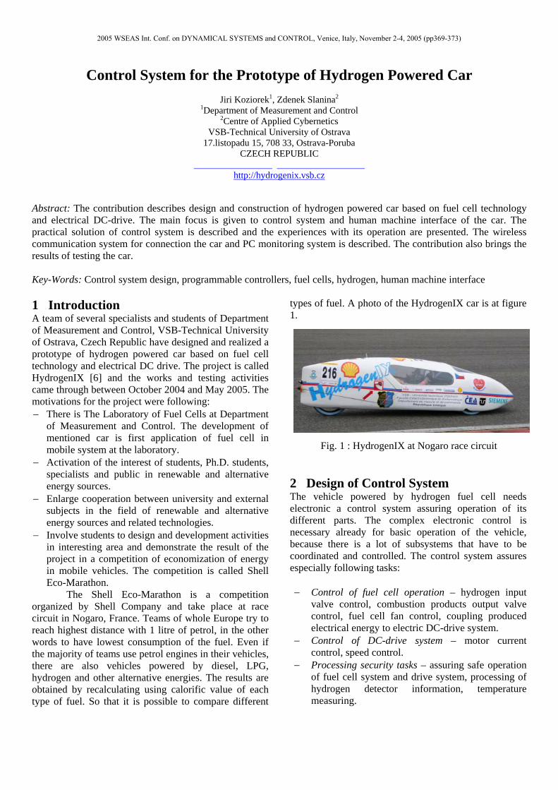
The Shell Eco-Marathon is a competition organized by Shell Company and take place at race circuit in Nogaro, France. Teams of whole Europe try to reach highest distance with 1 litre of petrol, in the other words to have lowest consumption of the fuel. Even if the majority of teams use petrol engines in their vehicles, there are also vehicles powered by diesel, LPG, hydrogen and other alternative energies. The results are obtained by recalculating using calorific value of each type of fuel. So that it is possible to compare different
types of fuel. A photo of the HydrogenIX car is at figure 1.
Fig. 1 : HydrogenIX at Nogaro race circuit 2 Design of Control System The vehicle powered by hydrogen fuel cell needs electronic a control system assuring operation of its different parts. The complex electronic control is necessary already for basic operation of the vehicle, because there is a lot of subsystems that have to be coordinated and controlled. The control system assures especially following tasks: − Control of fuel cell operation – hydrogen input
valve control, combustion products output valve control, fuel cell fan control, coupling produced electrical energy to electric DC-drive system.
− Control of DC-drive system – motor current control, speed control.
− Processing security tasks – assuring safe operation of fuel cell system and drive system, processing of hydrogen detector information, temperature measuring.
2005 WSEAS Int. Conf. on DYNAMICAL SYSTEMS and CONTROL, Venice, Italy, November 2-4, 2005 (pp369-373)
− Managing the driver control panel – complete interface to pilot that allows controlling the car – start/stop, speed set point, time measuring, emergency buttons and indicators.
− Creating data archives with saved process variables – saving important process data to archives that can be then exported and analyzed.
− Sending actual data to display panel in car – display panel in the car is the “process” visualization of the system. All important data are online displayed on it.
− Communication with PC monitoring station – control system send data and receive commands from PC monitoring station using wireless communication system.
Before choosing concrete control system, an analysis of system requirements was made. The results are following: − The control system must be able to process at least
10 digital inputs and 10 digital outputs. − The control system must be able to process at least
6 analog inputs and 1 analog output. − The control system must have 1 PWM output with
frequency at least 10 kHz. − The control system must be able to read pulse
inputs at frequency at least 20 kHz. − The control system should have power
consumption as low as possible. − Electrical installation in car uses 24V so that
control system must be able to manage digital signals at this range.
On the basis of the analysis, the programmable controller Siemens Simatic S7 224XP with EM235 expanding module was chosen as control device [4]. This control device fulfills all of the requirements. Using programmable controller for the car control is not commonly used (normally are used embedded systems based on microcontroller or DSP) [5] but in prototype application it is acceptable and moreover it brings several advantages. The first advantage is the fact the programmable controller is complete system, there is no need of hardware design and testing and it markedly reduces the time of development process. The programmable controller use demanded voltage ranges of the signals, no conversion is necessary. All communication drivers and tools are available. Power consumption is approximately 3-4 W which is sufficient for mentioned application.
In the other hand, there are also disadvantages of using PLC at such kind of application. Embedded systems based on microcontroller or DSP can conform better the requirements than universal programmable controller, computing power can be higher, dimensions and consumption can be lower.
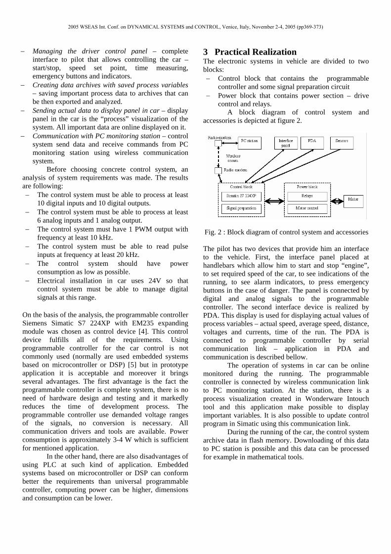
3 Practical Realization The electronic systems in vehicle are divided to two blocks: − Control block that contains the programmable
controller and some signal preparation circuit − Power block that contains power section – drive
control and relays. A block diagram of control system and
accessories is depicted at figure 2.
Fig. 2 : Block diagram of control system and accessories
The pilot has two devices that provide him an interface to the vehicle. First, the interface panel placed at handlebars which allow him to start and stop “engine”, to set required speed of the car, to see indications of the running, to see alarm indicators, to press emergency buttons in the case of danger. The panel is connected by digital and analog signals to the programmable controller. The second interface device is realized by PDA. This display is used for displaying actual values of process variables – actual speed, average speed, distance, voltages and currents, time of the run. The PDA is connected to programmable controller by serial communication link – application in PDA and communication is described bellow.
The operation of systems in car can be online monitored during the running. The programmable controller is connected by wireless communication link to PC monitoring station. At the station, there is a process visualization created in Wonderware Intouch tool and this application make possible to display important variables. It is also possible to update control program in Simatic using this communication link.
During the running of the car, the control system archive data in flash memory. Downloading of this data to PC station is possible and this data can be processed for example in mathematical tools.
2005 WSEAS Int. Conf. on DYNAMICAL SYSTEMS and CONTROL, Venice, Italy, November 2-4, 2005 (pp369-373)
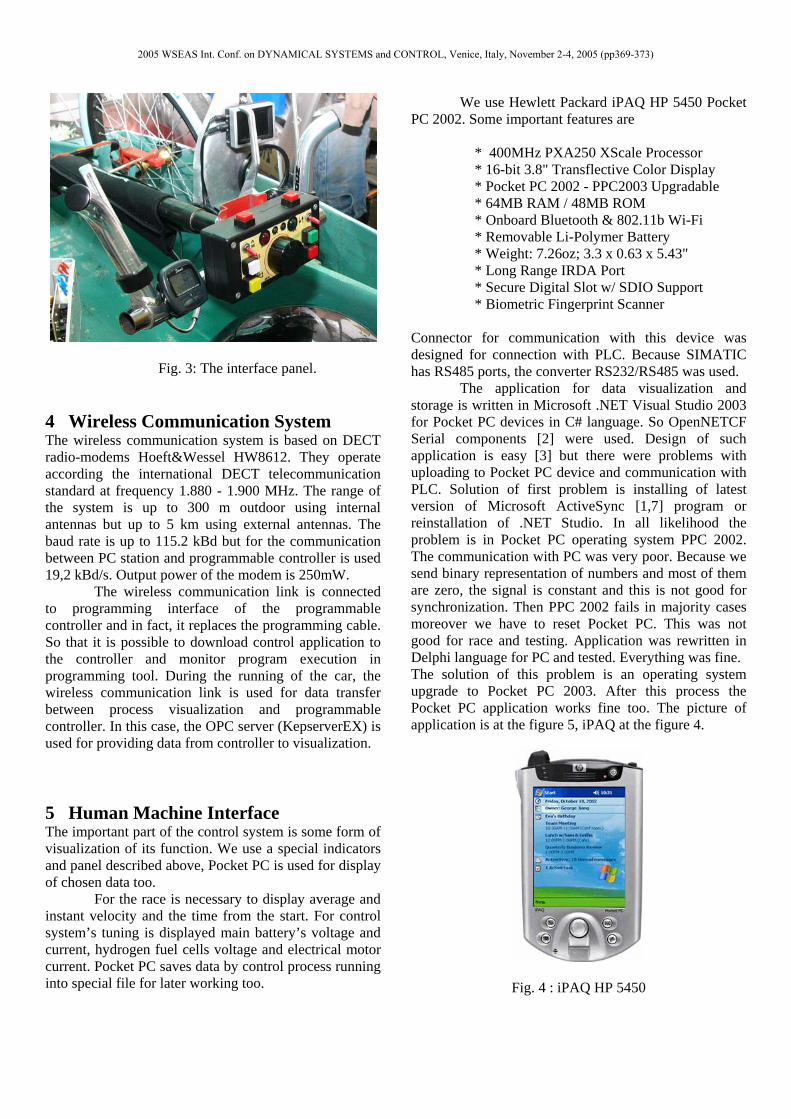
Fig. 3: The interface panel. 4 Wireless Communication System The wireless communication system is based on DECT radio-modems Hoeft&Wessel HW8612. They operate according the international DECT telecommunication standard at frequency 1.880 - 1.900 MHz. The range of the system is up to 300 m outdoor using internal antennas but up to 5 km using external antennas. The baud rate is up to 115.2 kBd but for the communication between PC station and programmable controller is used 19,2 kBd/s. Output power of the modem is 250mW.
The wireless communication link is connected to programming interface of the programmable controller and in fact, it replaces the programming cable. So that it is possible to download control application to the controller and monitor program execution in programming tool. During the running of the car, the wireless communication link is used for data transfer between process visualization and programmable controller. In this case, the OPC server (KepserverEX) is used for providing data from controller to visualization.
5 Human Machine Interface The important part of the control system is some form of visualization of its function. We use a special indicators and panel described above, Pocket PC is used for display of chosen data too.
For the race is necessary to display average and instant velocity and the time from the start. For control system’s tuning is displayed main battery’s voltage and current, hydrogen fuel cells voltage and electrical motor current. Pocket PC saves data by control process running into special file for later working too.
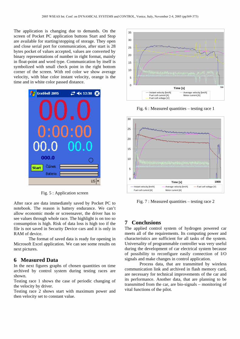
We use Hewlett Packard iPAQ HP 5450 Pocket PC 2002. Some important features are
* 400MHz PXA250 XScale Processor * 16-bit 3.8" Transflective Color Display * Pocket PC 2002 - PPC2003 Upgradable * 64MB RAM / 48MB ROM * Onboard Bluetooth & 802.11b Wi-Fi * Removable Li-Polymer Battery * Weight: 7.26oz; 3.3 x 0.63 x 5.43" * Long Range IRDA Port * Secure Digital Slot w/ SDIO Support * Biometric Fingerprint Scanner
Connector for communication with this device was designed for connection with PLC. Because SIMATIC has RS485 ports, the converter RS232/RS485 was used. The application for data visualization and storage is written in Microsoft .NET Visual Studio 2003 for Pocket PC devices in C# language. So OpenNETCF Serial components [2] were used. Design of such application is easy [3] but there were problems with uploading to Pocket PC device and communication with PLC. Solution of first problem is installing of latest version of Microsoft ActiveSync [1,7] program or reinstallation of .NET Studio. In all likelihood the problem is in Pocket PC operating system PPC 2002. The communication with PC was very poor. Because we send binary representation of numbers and most of them are zero, the signal is constant and this is not good for synchronization. Then PPC 2002 fails in majority cases moreover we have to reset Pocket PC. This was not good for race and testing. Application was rewritten in Delphi language for PC and tested. Everything was fine. The solution of this problem is an operating system upgrade to Pocket PC 2003. After this process the Pocket PC application works fine too. The picture of application is at the figure 5, iPAQ at the figure 4.
Fig. 4 : iPAQ HP 5450
2005 WSEAS Int. Conf. on DYNAMICAL SYSTEMS and CONTROL, Venice, Italy, November 2-4, 2005 (pp369-373)
The application is changing due to demands. On the screen of Pocket PC application buttons Start and Stop are available for starting/stopping of storage. They open and close serial port for communication, after start is 28 bytes pocket of values accepted, values are converted by binary representations of number in right format, mainly in float-point and word type. Communication by itself is symbolized with small check point in the right bottom corner of the screen. With red color we show average velocity, with blue color instant velocity, orange is the time and in white color passed distance.
Fig. 5 : Application screen
After race are data immediately saved by Pocket PC to notebook. The reason is battery endurance. We can’t allow economic mode or screensaver, the driver has to see values through whole race. The highlight is on too so consumption is high. Risk of data loss is high too if the file is not saved in Security Device cars and it is only in RAM of device.
The format of saved data is ready for opening in Microsoft Excel application. We can see some results on next pictures.
6 Measured Data In the next figures graphs of chosen quantities on time archived by control system during testing races are shown. Testing race 1 shows the case of periodic changing of the velocity by driver. Testing race 2 shows start with maximum power and then velocity set to constant value.
0
5
10
15
20
25
30
35
Time [s] 720
Instant velocity [km/h] Average velocity [km/h]Fuel cell current [A] Motor current [A]Fuel cell voltage [V]
Fig. 6 : Measured quantities – testing race 1
0
5
10
15
20
25
30
Time [s] 1900Instant velocity [km/h] Average velocity [km/h] Fuel cell voltage [V]Fuel cell current [A] Motor current [A]
Fig. 7 : Measured quantities – testing race 2
7 Conclusions The applied control system of hydrogen powered car meets all of the requirements. Its computing power and characteristics are sufficient for all tasks of the system. Universality of programmable controller was very useful during the development of car electrical system because of possibility to reconfigure easily connection of I/O signals and make changes in control application. Process data, that are transmitted by wireless communication link and archived in flash memory card, are necessary for technical improvements of the car and its performance. Another data, that are planning to be transmitted from the car, are bio-signals – monitoring of vital functions of the pilot.
2005 WSEAS Int. Conf. on DYNAMICAL SYSTEMS and CONTROL, Venice, Italy, November 2-4, 2005 (pp369-373)
The HydrogenIX team is just working at modified version of the car. The conception of control system will rest similar, changes will be realized in software and electrical installation.
Acknowledgement: This work was supported by the Ministry of
Education of the Czech Republic under Project 1M6840770004 – Centre of Applied Cybernetics.
The work and the contribution were supported by the project Grant Agency of Czech Republic - Architectures of embedded system networks, No. 102/65/0571 References: [1] Microsoft web pages - www.microsoft.com [2] OpenNETCF - Smart Device Framework:
http://www.opennetcf.org/ [3] WIGLEY, A., ROXBURGH, P.: ASP.NET
applications for Mobile Devices, Microsoft Press, Redmond, 2003. ISBN 073561914X.
[4] SIEMENS: Simatic S7 200 Programmable Controller, System Manual. Edition 06/2004.
[5] SROVNAL, V., KOTZIAN, J.: Development of Embedded Control System for Mobile Objects Using UML. In IFAC Workshop PDS 2004, Gliwice, Polsko:IFAC WS 2004 0008 PL, 2004, p.293-298, IFAC, ISBN 83-908409-8-7.
[6] Koziorek, J.: Projekt HydrohenIX - present and visions. In FCA 2005 (Fuel Cells and Applications, Ostrava2005), VŠB-TU Ostrava:, 2005, p. 27-29.
[7] Microsoft mobile web pages – http://www.microsoft.com/windowsmobile/
2005 WSEAS Int. Conf. on DYNAMICAL SYSTEMS and CONTROL, Venice, Italy, November 2-4, 2005 (pp369-373)