Control system for improved cylinder torque balance of engine
24
Transcript of Control system for improved cylinder torque balance of engine

United States Patent [191 Shimizu et a].
USOO574078OA
[54] CONTROL SYSTEM FOR IIVIPROVED CYLINDER TORQUE BALANCE OF ENGINE
[75] Inventors: Hirokazu Shimizu; Kenichi Madiida, both of Gunma, Japan
[73] Assignee: Unisia Jecs Corporation, Atsugi, Japan
[21] Appl. No.: 795,851
[22] Filed: Feb. 5, 1997
[30] Foreign Application Priority Data
Feb. 5, 1996 [JP] Japan .................................. .. 8-019017
[51] Int. cl.‘5 ...................................................... .. F02B 5/14
[52] US. Cl. 123/425 [58] Field of Search ...................... .. 123/425; 364/431.08
[56] References Cited
U.S. PATENT DOCUMENTS
5,488,868 2/1996 Ootake et a1. .......................... .. 73/708
5,503,007 4/1996 Plee et a1. . . . . . . . . . . . . . . . .. 73/116
5,508,927 4/1996 Remboski et al. .. 364/43l.08 5,535,722 7/1996 Graessley et al. .. 123/425 5,546,905 8/1996 Fukui ........................ .. 123/425
5,632,247 5/1997 Hashizume et a1. .................. .. 123/425
[11] Patent Number: 5,740,780 [45] Date of Patent: Apr. 21, 1998
5,645,034 7/1997 Entenmann et a1. .................. .. 123/425
FOREIGN PATENT DOCUMENTS
63-17432 2/1988 Japan ................................... .. 123/425
OTHER PUBLICATIONS
“Guide for Nissan Ce?ro of the A32 Type Series”. published in Japan in Aug. 1994 by Nissan Motor Co., Ltd., pp. 18. 38-44, 56-58. “Guide for Nissan Cedric Gloria of the Y33 Type Series” published in Japan in Jun. 1996 by Nissan Motor Co., Ltd.
Primary Examiner-Raymond A. Nelli Attorney, Agent, or Firm—Foley & Lardner
[57] ABSTRACT
Cylinder to cylinder variation in developed cylinder torque is suppressed by correcting ignition timings for the indi vidual cylinders or by correcting fuel injection amounts allocated to the individual cylinders. Amounts of correction to be made to the individual ignition timings or fuel injection amounts are determined as results of comparison of indi vidual cylinder pressure averages with a multiple cylinder pressure average that is an average of the individual cylinder pressure averages.
12 Claims, 16 Drawing Sheets
US. Patent Apr. 21, 1998 Sheet 1 of 16 5 ,7 40,7 80
FIG.1
J// 1
TVO
C/u
36

US. Patent Apr. 21, 1998 Sheet 2 0f 16 5,740,780
FIG.2
ARE PRED. CONDITIONS
MET ?
DETERMINE N54 DEVELOPED TORQUE PARAMETERS IMEPn OF INDIvIDuAI. CYLINDERS
II
DETERMINE INDIVIDUAL 56 CYLINDER AVERAGES N lIPlMAn OF CYLINDERS & MULTIPLE CYLINDER AVERAGE IPIMAV
II
DETERMINE CORRECTION 58 AMOUNT REIPAI ' OF NO.1 CYLINDER
I DETERMINE CORRECTION 60
AMOUNT REIPA3 ’" OF NO.3 CYLINDER
I DETERMINE CORRECTION /-/
AMOUNT REIPA4 OF NO.4 CYLINDER
I DETERMINE CORRECTION 64
AMOUNT REIPA2 PT OF NO.2 CYLINDER
I OUTPUT:REIPA1, 55 REIPA3 REIPA4 ’
& REIPA2
62
END

US. Patent Apr. 21, 1998 Sheet 3 0f 16 5,740,780
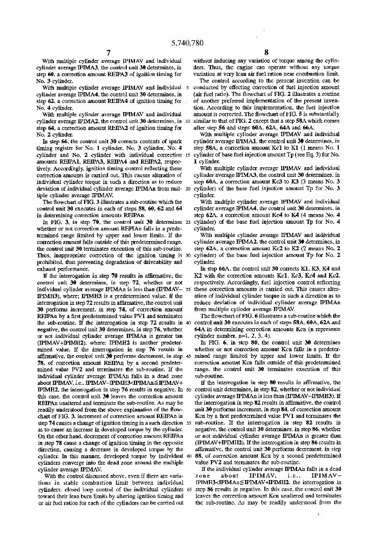
FIG.3
70 IS RElPAn
WITHIN PRED. RAIgGE
lPIMAn < IPIMAV - IPIMH3 ‘.7
YE S 74 /.
RElPAn : REIPAn + PV1
lPlMAn > IPIMAV + IPIMH2 ?
YES REIPAI’] = REIPAI'I - PV2
END

Apr. 21, 1998 Sheet 4 0f 16 5,740,780
FIG.4
mmDwwmmm mmDZI>O
US. Patent
240 260 280 300 320 340 360 380 400 420 440 460 480 500
CRANKSHAFT ANGLE (°C)
US. Patent Apr. 21, 1998 Sheet 5 0f 16
FIG.5
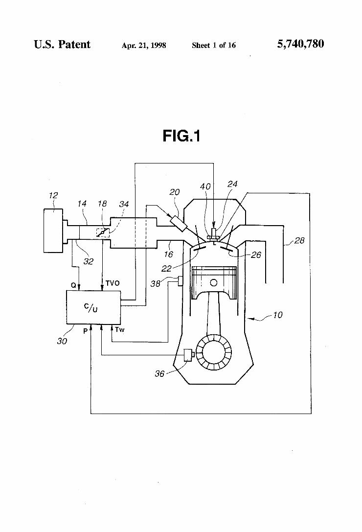
52 ARE PRED. CONDITIONS
MET '?
DETERMINE ~54 DEVELOPED TORQUE PARAMETERS lMEPn OF INDIVIDUAL CYLINDERS
I
DETERMINE INDIVIDUAL 56 CYLINDER AVERAGES r" IIPIMAn OF CYLINDERS & MULTIPLE CYLINDER AVERAGE IPIMAV
II
AMOUNT K01 OF NO.1 CYLINDER DETERMINE CORRECTION i814
I
AMOUNT K63 OF NO.3 CYLINDER DETERMINE CORRECTION JOA
I
AMOUNT Kc4 OF NO.4 CYLINDER DETERMINE CORRECTION WQZA
AMOUNT Kc2 0F NO.2 CYLINDER DETERMINECORRECTION /_§4A
END
5,740,780

US. Patent Apr. 21, 1998 Sheet 6 0f 16 5,740,780
FIG.6
80 IS Kcn
WITHIN PRED.
RAQGE
lPIMAn < IPIMAV — |P|MH3 ?
Y ES f 84
Ken = Kcn + PV1
lPlMAn > IPIMAV
Kcn = Kcn - PV2
US. Patent Apr. 21, 1998 Sheet 7 0f 16
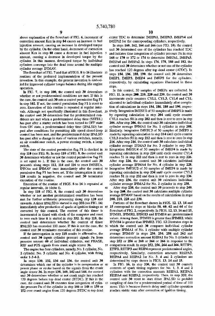
FIG.7
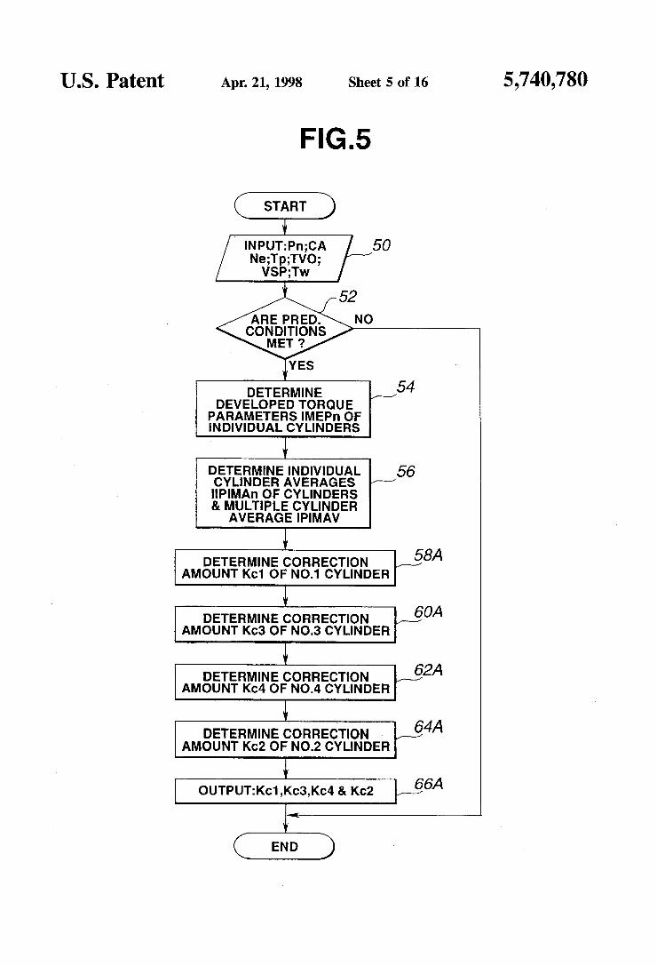
100 ARE PRED. CONDITIONS
MET?
V [104 F1 || 0
5,740,780

U.S. Patent Apr. 21, 1998 Sheet 8 0f 16
IMESUn = o, lPlNAn = o, IPIMAV = 0,
n=10R20R30R4
IPALSD > 100 msec. ?
lNPUT:Pn (n = 1 0R 3 on 4);
PHASE SIGNAL; REF SIGNAL; POS SIGNAL
é
5,740,780

US. Patent Apr. 21, 1998 Sheet 9 of 16 5,740,780
FIG.9 6
130
IS NO.1 CYLINDER IN COMPRESSION OR POWER
PH'ASE
NO
132
YES IS No.3 CYLINDER IN COMPRESSION OR POWER PHASE
‘.7
138 No
134 HAS CRANK
ANGLE REACHED 120 DEGREES YES IS No.4
CYLINDER IN N BTvDC COMPRESSION o
' 0R POWER
PH’I’ASE 736 No HAS CRANK
@
ANGLE REACHED 120 DEGREES YES CYENNég m
BT96 COMPRESSION o - 0R POWER
PHASE 140 No HAS CRANK ?
ANGLE REACHED 120 DEGREES 144
BTDC
0 "’ , 142 HAS CRANK
ANGLE REACHED lMEPb1 = lMEPb1 120 DEGREES
+ P1 x delta t BTDC ?
lMEPb4 = IMEPb4 146 + P4 x delta t YES
150 lMEPb3 = lMEPb3 _
+ P3 X delta t |ME2Ib22x_d|g||tEa‘-ib2
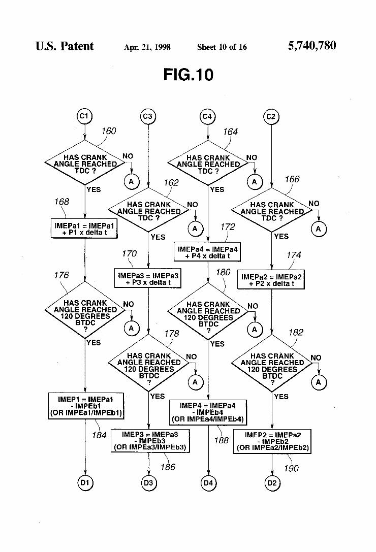
U.S. Patent Apr. 21, 1998 Sheet 10 of 16 5,740,780
FIG.10
HAS CRANK
168
lMEPa1 = |MEPa1 + P1 x delta t
IMEP84 : |MEPa4
1<0 +P4xdeltat 7/74 |MEPa3 = |MEP33 |MEP32 = lMEPa2 + P3 X delta t + P2 X delta t
HAS CRANK ANGLE REACHED 120 DEGREES
BT'PC
HAS CRANK ANGLE REACHED 120 DEGREES
BT'PC
HAS CRANK ANGLE REACHED 120 DEGREES
BT'PC
HAS CRANK ANGLE REACHED 120 DEGREES
BTDC
IMEP1 : lMEPa1 - lMPEb1
(OR lMPEa1/lMPEb1)
IMEP3 = lMEPa3 \ IMEP2 : IMEPa2 184 - IMPEb3 188 - lMPEb2
(OR lMPEa3/IMPEb3) (OR lMPEa2/IMPEb2)
IMEP4 : IMEPa4 - IMPEb4
(OR lMPEa4/IMPEb4)
186 >90
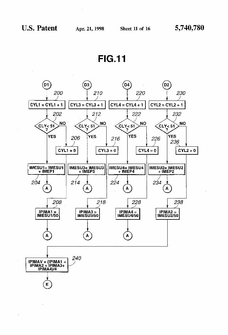
US. Patent Apr. 21, 1998 Sheet 11 0f 16 5,740,780
FIG.11
Q)? 200 210 / /
220 230 , / /
CYL1 : CYL1 +1 CYL3 : CYL3 + 1 CYL4 = CYL4 + 1 CYL2 : CYL2 +1
202
NO
YES
1
CYL
IMESU1: IMESU1 IMESUS: IMESU3 IMESU4: IMESU4 |MESU2= mlEsuz + IMEP1 + IMEPS + IMEP4 + IMEP2
/ / / / 204 214 224 ~ 234
208 218 228 238 / v / / v /
IPIMA1 = IPIMA3 = IPIMA4 = IPIMA2 = IMESU1/50 IMESU3I50 IMESU4/50 IMESUZ/SO
v 240 IPIMAV = IPIMA1 + / IPIMA2 + PIMA3+
lPlMA4)/4
é


U.S. Patent Apr. 21, 1998 Sheet 14 of 16 5,740,780
FIG.14
IPIMAV+IPIMH1§ IPIMA4?
294
298
YES
r292 ‘ f296 f3OO REIPA4=REIPA4 REIPA4=REIPA4 _
+ RETIP1 + RETIPZ RE'PM'HE'PM
302
YES 304 306
f v / REIPA4=REIPA4 REIPA4=REIPA4
- news - RETIP4


US. Patent Apr. 21, 1998
FIG.16
Sheet 16 0f 16
[330 CORRECT CONTENTS OF SPARK TIMING
REGISTERS FOR NO. 1, 2 4 81 2 CYLINDERS WITH REIPA1, REIPA3 REIPA4 & REIPA2, RESPECTIVELV
[332 START TIMER IPALSD
END
$9
5,740,780

1 CONTROL SYSTEM FOR IMPROVED
CYLINDER TORQUE BALANCE OF ENGINE
BACKGROUND OF THE INVENTION
The present invention relates to a control system for an engine with electronic control to optimize engine operation for improved cylinder torque balance.
It is known to adjust air fuel ration or ignition timing for engine operation near the limit of stable engine operation. Speci?cally. fuel control to increase air fuel ration of com »bustible mixture distributed to all cylinders or ignition timing control to retard ignition timing of the cylinders are carried out based on cylinder pressures to keep torque variation rate not to exceed an engine stable operation limit.
It is conceivable to conduct such controls on cylinder to cylinder basis for cylinder operation with increased air fuel ratio or at more retarded ignition timing. In the case where there are cylinder to cylinder variations in lean limit and retard limit. cylinder to cylinder variations in air fuel ratio and ignition timing are brought about. impairing cylinder torque balance. An object of the present invention is to an engine control
system with precision but simple control to reduce cylinder to cylinder torque variations to improve torque balance.
SUMMARY OF THE INVENTION
According to one aspect of the present invention, there is provided a control system for cylinder torque balance of an internal combustion engine including multiple cylinders, comprising: means for determining individual cylinder torque having
been developed by the cylinders of the engine; means for calculating, out of the determined individual
cylinder torque, a multiple cylinder average; and means for controlling a control variable on which indi
vidual cylinder torque depends in such a manner as to decrease a deviation of the determined individual cylinder torque from the determined multiple cylinder average.
According to another aspect of the present invention, there is provided a control method for cylinder torque balance of an internal combustion engine including multiple cylinders, comprising the steps of: ‘
determining individual cylinder torque having been developed by the cylinders of the engine;
calculating, out of the determined individual cylinder torque. a multiple cylinder average; and
controlling a control variable on which individual cylin der torque depends in such a manner as to decrease a deviation of the determined individual cylinder torque from the determined multiple cylinder average.
Speci?cally, there is provided according to the present invention an improved control unit means for an ignition timing control system for an internal combustion engine including a plurality of spark plugs for cylinders of the engine, respectively. the plurality of spark plugs providing sparks in response to individual spark timing commands, and control unit means for developing the individual spark timing commands. The control unit means inputs information of cylinder
pressure within each of the engine cylinders over crank angles about top dead center (TDC) over a predetermined number of cycles. The control unit means determines. for each of the
cylinders. a ratio. as a developed torque parameter. between
5,740,780
10
15
25
35
45
55
65
2 integral of cylinder pressure over a predetermined angle after top dead center and integral of cylinder pressure over a predetermined crank angle before top dead center. The control unit means calculates integral of said deter
mined developed torque parameter over said predetermined number of cycles and calculates an individual cylinder average for each of the cylinders. The control unit means calculates a multiple cylinder
average out of said individual cylinder averages of the cylinders. The control unit means compares each of said individual
cylinder averages with said multiple cylinder average. The control unit means determines correction amounts to
the ignition timing commands in response to results of comparing each of said individual cylinder averages with said multiple cylinder average, respectively.
BRIEF DESCRIPTION OF THE DRAWINGS
FIG. 1 is a diagram illustrating a control system for improved cylinder torque balance of a multiple cylinder internal combustion engine;
FIG. 2 is a flowchart of a main routine illustrating a preferred implementation of a control strategy according to the present invention;
FIG. 3 is a ?owchart of a sub-routine.
FIG. 4 is a graphical representation of cylinder pressure (P) versus crankshaft angle during compression and power phases;
FIG. 5 is a ?owchart of a main routine illustrating another preferred implementation of a control strategy according to the present invention;
FIG. 6 is a ?owchart of a sub-control routine;
FIG. 7 is a ?owchart illustrating a control permission ?ag setting routine for determining whether or not predetermined conditions are met; and
FIGS. 8 to 16 show a ?owchart of a routine for cylinder torque balance during engine operation at idle speeds.
DETAILED DESCRIPTION OF THE INVENTION
Referring to FIG. 1. a four-stroke internal combustion engine is generally designated by the reference numeral 10. The engine 10 has four cylinders, namely, No. 1 cylinder No. 2 cylinder, No. 3 cylinder and No. 4 cylinder, in this embodiment. In FIG. 1, for the sake of simplicity. the No. 1 cylinder is illustrated as representative of each of the cyl inders of the engine 10. Intake air is admitted to the engine 10 through an air cleaner 12. an air induction duct 14 and an intake manifold 16.
Disposed within the air induction duct 14 is a throttle valve 5 which opens in degrees by a gas pedal or an accelerator. not shown. Flow of air admitted to the engine can be regulated by the throttle valve 5. The intake manifold 16 includes four branches extending
toward the four cylinders, respectively. Four fuel injection valves. only one being shown at 20. are arranged to direct jets of fuel into the four branches, respectively. With elec tronic control. amount of fuel to be injected by each of the fuel injection valves 20 can be adjusted independently. so that ditferent air fuel mixtures may be formed in the cylinders. respectively. if desired.
During induction stroke. while an inlet valve 22 is open. a descending piston draws fresh air fuel mixture into one of the cylinders. During compression stroke. While both inlet

5,740,780 3
and exhaust valves 22 and 26 are closed, the rising piston compresses the mixture. Then, the mixture is ignited by a spark plug 24. During power stroke, while the valves 22 and 26 are closed, the pressure of the gases of combustion forces the piston downwards. During exhaust stroke, the exhaust valve 26 is open and the rising piston discharges the spent gases from the cylinder. The gases discharged pat the exhaust valve 26 are directed by an exhaust manifold 28 toward a catalytic converter and then to a mu?ler, not shown.
Electronic controls to optimize amount of fuel injection and ignition timing are carried out by a control unit 30. The control unit 30 includes a microcomputer including a central processor unit (CPU), a read only memory (ROM). a ran dom access memory (RAM). an input interface unit and an output interface unit. An air ?ow meter of the hot wire type 32 is provided for
measuring ?ow rate of intake air upstream of the throttle valve 18 and provides as an output an intake air ?ow rate signal Q indicative of the measured ?ow of air passing through the air induction duct 14 upstream of the throttle valve 18. A throttle sensor 34 is provided for measuring throttle opening degree in which the throttle valve 18 opens and provides as an output a throttle valve opening degree signal TVO indicative of the measured throttle opening degree. With this throttle sensor 34. it can be determined whether or not the engine 10 is idling by comparing the current sensor output with a minimum value of stored data of sensor output during previous engine operation. If desired. a throttle sensor incorporating idle contacts may be provided. In this case. it can be determined that the engine is idling by checking whether or not the idle contacts are closed. A crankshaft angle sensor 36 is provided for mea suring crankshaft angle and provides as an output a crank shaft angle signal CA indicative of the measured crankshaft angle. A water temperature sensor 38 is provided for mea suring temperature of water for the engine and provides as an output a water temperature signal Tw indicative of the measured water temperature. Cylinder pressure sensors, only one being shown at 40. are provided for measuring pressures within the cylinders, respectively. Each of the cylinder pressure sensors provides as an output a cylinder pressure signal P indicative of the measured cylinder pres sure. All of the outputs are fed to the control unit 30. The air ?ow meter 32 generates, as the air ?ow signal Q.
electric voltage proportional to the flow of air passing through the air induction duct 14. The throttle sensor 34 is in the form of a potentiometer. The crankshaft angle sensor 36 includes a magnetic type reference (REF) sensor. a magnetic type position (8) sensor and a magnetic type phase (PHASE) sensor. The REF and POS sensors are provided to detect position of a crankshaft of the‘ engine 10. while the PHASE sensor is provided to detect position of a camshaft of the engine 10. The REF sensor includes a signal plate attached to or integral with a crank pulley connected to the crankshaft for unitary rotation therewith. The POS sensor includes a signal plate attached to or integral with a ?ywheel for a manual transmission or to a drive plate for an automatic transmission. The PHASE sensor includes a signal plate attached to or integral with a primary crankshaft sprocket. The REF sensor is provided to detect a reference position of each of the cylinders, Le. a position predetermined degrees before the top dead center (TDC) of the piston in the cylinder. Speci?cally. the REF sensor generates a REF signal at the reference position upon every rotation of the crankshaft through a predetermined angle. for example 180 degrees for the four cylinders. The POS sensor generates a POS signal upon every rotation of the crankshaft through 1
10
15
25
45
55
65
4 (one) degree. The PHASE sensor generates a PHASE signal at such a rate that number of occurrence of PHASE signal within an interval between one and the subsequent occur rences of REF signal represents cylinder number whose ascending piston is about to reach TDC immediately after the subsequent occurrence of REF signal. In determining engine speed Ne. number of occurrence of POS signal for a unit time is counted. Alternatively, number of occurrence of REF signal may be counted for a unit time to determine engine speed Ne. In identifying cylinder number, number of occurrence of PHASE signal is counted. The water tempera ture sensor 38 employs a thermistor having resistor that varies with temperature of the water. The air ?ow meter 32, throttle sensor 36, cranking angle sensor 36 and water temperature sensor 38 are described on pages B-18, B-38. B-56 to 13-58 of a guide book entitled “GUIDE FOR NISSAN CEFIRO OF THE A32 TYPE SERIES” published in Japan in August 1994 by Nissan Motor Co., LTD. On page B-18 of this guide book, there are described a crank pulley within an integral signal plate of a REF sensor, a ?ywheel integral with a signal plate of a PCS sensor, and a drive plate integral with a signal plate of a POS sensor. On page 5-38 of the guide book, there is described a crankshaft angle sensor composed of a REF sensor, a POS sensor and a PHASE sensor. On Page B-56 of the guide book. there are photographs of the REF sensor and POS sensor with brief explanations. On page B-57 of the guide book, there are photographs of the PHASE sensor, an air ?ow meter and a water temperature with brief explanations. On Page B-58 of the guide book, there is a photograph of a throttle sensor. The cylinder pressure sensors 40 are arranged to all of the
cylinders. respectively. Each of them includes a washer of piezoelectric material used as a washer of the corresponding one spark plug 24. The cylinder pressure sensor of this type is disclosed in JP-A 63-17432 U. For brevity, further expla nation of cylinder pressure is omitted. Of course, other type of pressure sensor may be used, such as a cylinder pressure directly detecting cylinder pressure within the cylinder. Based on information derived from the REF, POS and.
PHASE signals of the crankshaft angle sensor 36, the water temperature signal W of the water temperature sensor 38 and the output of the throttle sensor 34. the control unit 30 determines current engine speed, Water temperature and throttle opening degree. For determining an ordinary igni tion timing, the control unit 30 performs a table look-up operation of an appropriate map based on the determined engine speed, water temperature and throttle opening degree. This operation results in giving a base ignition timing which is a major term of an equation used for calculating the ordinary ignition timing. This equation includes various correction terms in addition to the major term. ‘The control unit 30 determines the correction terms and calculates this equation to determine the ordinary igni tion timing. The control unit 30 is connected with each of ignition coils at a built-in power transistor thereof. The ignition coils are directly coupled with all of the spark plugs 24, respectively. The ignition coil of the above mentioned type is known and disclosed on page 13-111 of a guide book entitled “GUIDE FOR NISSAN CEDRIC GLORIA OF THE Y33 TYPE SERIES” published in Japan in June 1996 by Nissan Motor Co., Ltd. Among the correction terms of the equation, there is a
knocking correction term. The control unit 30 receives information of cylinder pressure in each of the cylinders from outputs of all of the cylinder pressure sensors 40 to process the information to ?nd which one of the cylinders experienced knocking, if occurred. and modify the knocking