Control relays and protection - KREPEL
49
Control relays and protection
Transcript of Control relays and protection - KREPEL
Control relaysand protection
Control relays
General characteristics
Direct settingFrontal direct setting
and reading of measurement
thresholds and time delays
Specifi c transformer
Oversized transformer stands supply
variations and fi lters disturbances
On product informationWiring and relay characteristics on side Product easy recognition with reference on face.
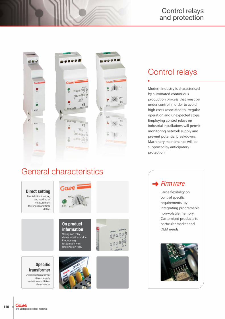
Modern industry is characterised by automated continuous production process that must be under control in order to avoid high costs associated to irregular operation and unexpected stops. Employing control relays on industrial installations will permit monitoring network supply and prevent potential breakdowns. Machinery maintenance will be supported by anticipatory protection.
FirmwareLarge flexibility on control specific requirements by integrating programable non-volatile memory. Customised products to particular market and OEM needs.
Control relays and protection
low voltage electrical material110

Control relays overview
MonitorControl relays are
measurement units that
continuously monitor
electrical values within
established parameters.
ControlOutput relays operate
with positive logic,
contacts are closed on
normal conditions and
will open when control
electronics detect
network faults.
ProtectionYour equipment is
protected against
network faults and all
associated damages.
SignallingOperating set, working
status and failure
conditions are informed
through rotary selectors
and signalling led
located on the front
face.
Aimed to protect motors where phase sequence is specially relevant (lifts, cranes, escalators,..) or phase failure can be specially damaging.
Phase Control
References
RF011 RF01 RF01A
Monitoring currents and temperature on mechanical loads such as motors, pumps and resistors increase protection on applications such as pumping, ventilation, lifts and conveyors.
Current and temperature monitoring
References
RC RTM
Industrial process requiring additional protection and preventive action install complex voltage monitoring relays that additional to phase failure and sequence protection offer voltage control within established threshold and adjustable timings. We find it in automation systems, refrigeration, network transfers.
Voltage Monitoring
References
RF02 RF02N RF-UT
RF03 RF03N
ApplicationsMotors• Moving equipment (cranes, • lifts, escalators,conveyors)Refrigaration•
Extraction fans• Pumps• Automatic transfer supplies• System automation•
low voltage electrical material
111www.gave.com

CharacteristicsMounting on symmetrical DIN rail• Connects when detecting: 3 phases•
correct phase sequence RST presenceTrips when detecting: phase failure•
incorrect phase sequencePhase failure is considered when nominal voltage is < 85% rated• Output changeover relay 5A / 250V AC cos φ = 1• Operating temperature: -10º to + 60ºC•
Phase Failure and Phase Sequence RelayVoltage monitoring relay for three phase supply.Protects against Phase Failure (loss) and Phase Sequence.
RF011
Diagram
Dimensions
Signalling
ON (red) R (green) Status
supply
incorrect phase sequence
phase failure
References Width (modules) Reset time Voltage
RF011 17,5mm (1) 0,1 sec. 208-480V AC
References
L1L1
L1
L1L2
L2
L2 L2
L3
L3
L3 L3
5 - 6contact
output
4 - 5
t
t
t
t
t
TM01
ON
4 5 6
R
A BC
D
EF
8 10
6
0,124
max. time
modes
1s 10s1m
10m
1h10h
1 2 3
90
5443
20,4
45 68,6
17,5
ON OFF BLINK
Control relays and protection
low voltage electrical material112

Phase Control
R (red) ON (green) Status
supply
incorrect phase sequence
phase failure
CharacteristicsMounting on symmetrical DIN rail• Connects when detecting: 3 phases presence•
correct phase sequence RST presenceTrips when detecting: voltage drop > 25%•
incorrect phase sequencePhase failure is considered when nominal voltage is < 75% rated• Output changeover relay 8A / 250V AC cos φ = 1• Operating temperature: -10º to + 60ºC•
Phase Failure and Phase Sequence RelayVoltage monitoring relay for three phase supply.Protects against Phase Failure (loss) and Phase Sequence.
RF01
Diagram
Signalling
References Width (modules) Reset time Voltage
RF01-230 35mm (2) 0,1 sec. 230 V
RF01-400 35mm (2) 0,1 sec. 400 V
References
Dimensions
L1
L2
L3
5 - 6contact
output
4 - 5
t
t
t
t
t
L1
L1
L1
L3
L2 L2
L2
L3 L3
RF01
ON
1 32 4 65
7 98 10 1211
R
modes
90
35
6049
26,1
45 68,6
ON OFF BLINK
low voltage electrical material
113www.gave.com

CharacteristicsMounting on symmetrical DIN rail• Adjustable phase failure tripping• Connects when detecting: 3 phases•
correct phase sequence RST presenceTrips when detecting: voltage drop under the preset voltage•
incorrect phase sequenceDetection of phase failure under preset value•
RF01A-230: adjustable from 150V to 250V RF01A-400: adjustable from 300V to 440V
Output changeover relay 8A / 250V AC cos φ = 1• Operating temperature: -10º to + 60ºC•
Adjustable Phase Failure and PhaseSequence Relay
Electronic relay for three phase supply monitoring and protecting against disturbances on the main supply.Protection against Phase Failure (loss) and Phase Sequence.Undervoltage adjustable.
RF01A
Diagram
Signalling
References Width (modules) Reset time Voltage
RF01A-230 35mm (2) 0,1 sec. 230 V
RF01A-400 35mm (2) 0,1 sec. 400 V
References
Dimensions
L1L1
L1
L1L2
L3
L2 L2
L3
L2
L3 L3
5 - 6contact
output
4 - 5
t
t
t
t
t
440
U
Umin
5 - 6contact
output
4 - 5
t
t
t
RF01A
ON
1 32 4 65
7 98 10 1211
R
A BC
D
EF
8 10
6
0,124
max. time
modes
1s 10s1m
10m
1h10h
90
35
6049
26,1
45 68,6
R (red)ON
(green)Status
supply
incorrect phase sequence
phase failure
ON OFF BLINK
Control relays and protection
low voltage electrical material114
Phase Control
Signalling
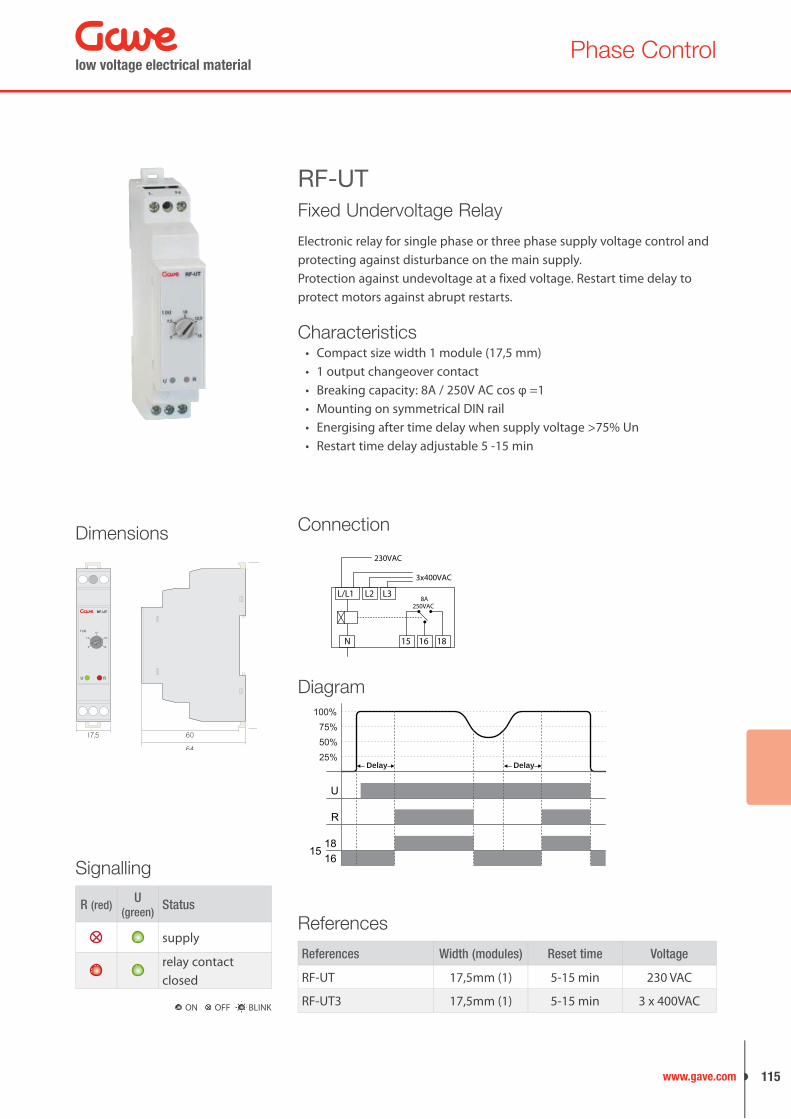
Fixed Undervoltage Relay
Electronic relay for single phase or three phase supply voltage control and protecting against disturbance on the main supply.Protection against undevoltage at a fixed voltage. Restart time delay to protect motors against abrupt restarts.
RF-UT
References Width (modules) Reset time Voltage
RF-UT 17,5mm (1) 5-15 min 230 VAC
RF-UT3 17,5mm (1) 5-15 min 3 x 400VAC
References
Dimensions
Diagram
Connection
230VAC
8A250VAC
15 16 18N
L/L1 L2 L3
3x400VAC
100%
U
R
1815
16
75%50%25%
Delay Delay
RU
5
7,5
10
12,5
15
RF-UT
t (s)
17,5 60
64
CharacteristicsCompact size width 1 module (17,5 mm)• 1 output changeover contact• Breaking capacity: 8A / 250V AC cos φ =1• Mounting on symmetrical DIN rail• Energising after time delay when supply voltage >75% Un• Restart time delay adjustable 5 -15 min•
R (red)U
(green)Status
supply
relay contact closed
ON OFF BLINK
low voltage electrical material
115www.gave.com

CharacteristicsMounting on symmetrical DIN rail• Connects when detecting: 3 phases within the set voltage•
correct phase sequence RST presenceTrips when detecting: phase failure, incorrect phase sequence, voltage • variationsAdjustable threshold (5 to 20%) for voltage variations (from 0,1 to 10 • seconds)Output changeover relay 8A / 250V AC cos φ = 1• Operating temperature: -10º to + 60ºC•
Phase Failure, Sequence and Voltagemonitoring RelayElectronic relay for three phase supply monitoring and protectingagainst disturbances on the main supply.Protection against Phase Failure (loss), Phase Sequence and Over/undervoltage.
RF02
References Width (modules) Reset time Voltage
RF02-230 35mm (2) 3min continuous input voltage within threshold
230 V
RF02-400 35mm (2) 400 V
RF02I-230 35mm (2)0,1sec.
230 V
RF02I-400 35mm (2) 400 V
References
Dimensions
DiagramL1
L1
L1
L1L2
L3
L2 L2
L3
L2
L3 L3
5 - 6contact
output
4 - 5
t
t
t
t
t
t1 t2
L3 L1
t1t2
L3
U
Umax
Umin
5 - 6contact
output
4 - 5
t
t
t
t
RF02
ON
1 32 4 65
7 98 10 1211
R
A BC
D
EF
8 10
6
0,124
max. time
1s 10s1m
10m
1h10h
90
35
6049
26,1
45 68,6
Signalling
R (red)ON
(green)Status
supply
incorrect phase sequence
voltage out of thresholdtiming to reset from voltage variation
phase failure
timing to reset from phase failure
ON OFF BLINK
Control relays and protection
low voltage electrical material116

Phase Control
CharacteristicsMounting on symmetrical DIN rail• Connects when detecting: 3 phases•
phase sequence RST+N is correctTrips when detecting either a phase failure, phase/neutral voltage • variations (adjustable threshold ±5 to ±20 %) or an incorrect phase sequence.Tripping time, for voltage variations, adjustable from: 0,1 to 10 seconds.• Tripping time for an incorrect phase sequence or phase failure: 0,1 sec. • Output: change over relay• Operating temperature: -10ºC to +60ºC•
Phase Sequence, Phase + Neutral Failure and Voltage monitoring RelayDetects an incorrect phase sequence. Detects a failure on any phase. Detects phase voltage variation
RF02N
Diagram
References Width (modules) Reset time Voltage
RF02N-230 35mm (2) 3min continuous input voltage within threshold
230 V
RF02N-400 35mm (2) 400 V
RF02NI-230 35mm (2)0,1sec.
230 V
RF02NI-400 35mm (2) 400 V
References
Signalling
Dimensions
L1
N
L2 N
L2
L1L3
L3 L1
N L2L3L1 L3
L1 L3NL2 L1
L3 L1L2N N
5 - 6contact
output
4 - 5
t
t
t
t
t
t1 t2
L3 L1
t1t2
L3
U
Umax
Umin
5 - 6contact
output
4 - 5
t
t
t
t
RF02N
ON
1 32 4 65
7 98 10 1211
R
A BC
D
EF
8 10
6
0,124
max. time
modes
1s 10s1m
10m
1h10h
90
35
6049
26,1
45 68,6
R (red)ON
(green)Status
supply
incorrect phase sequence
voltage out of thresholdtiming to reset from voltage variation
phase failure
timing to reset from phase failure
ON OFF BLINK
low voltage electrical material
117www.gave.com

CharacteristicsMounting on symmetrical DIN rail• Connects when detecting: 3 phases within the set voltage•
correct phase sequence RST presenceTrips when detecting: phase failure, incorrect phase sequence, phase • unbalanceTripping time delay adjustable against short time voltage variations• Phase unbalance adjustable threshold (5 to 15%)• Output changeover relay 8A / 250V AC cos φ = 1• Operating temperature: -10º to + 60ºC•
Phase Failure, Sequence and Unbalance RelayElectronic relay for three phase supply monitoring and protectingagainst disturbances on the main supply.Protection against Phase Failure (loss), Phase Sequence and Phase Unbalance.
RF03
Diagram
References Width (modules) Reset time Voltage
RF03-400 35mm (2)3min continuous input
voltage within threshold400 V
RF03I-400 35mm (2) 0,1sec. 400 V
References
L1L1
L1
L1L2
L3
L2 L2
L3
L2
L3 L3
5 - 6contact
output
4 - 5
t
t
t
t
t
t1 t2
U
5 - 6contact
output
4 - 5
t
t
t
t
Dimensions
RF03
ON
1 32 4 65
7 98 10 1211
R
A BC
D
EF
8 10
6
0,124
max. time
modes
1s 10s1m
10m
1h10h
90
35
6049
26,1
45 68,6
Signalling
ON OFF BLINK
R (red)ON
(green)Status
supply
incorrect phase sequence
voltage out of thresholdtiming to reset from voltage variation
phase failure
timing to reset from phase failure
Control relays and protection
low voltage electrical material118

Phase Control
CharacteristicsConnects when detecting: 3 phases•
phase sequence RST+N is correctTrips when detecting phase failure, a phase unbalance (adjustable • threshold 5 to 15 %) or an incorrect phase sequenceTripping time, for voltage variations, adjustable from: 0,1 to 10 seconds.• Tripping time for an incorrect phase sequence or phase failure: 0,1 sec. • Output: change over relay• Working temperature: -10ºC to +60ºC• Phase failure is considered when voltage is lower than 160V between • phase and neutral.
Phase Failure, Sequence and Unbalance RelayDetects an incorrect phase sequenceDetects a failure on any phaseDetects phase unbalance
RF03N
Diagram
References Width (modules) Reset time Voltage
RF03N-400 35mm (2)3min continuous input
voltage within threshold400 V
RF03NI-400 35mm (2) 0,1sec. 400 V
References
L1
N
L2 N
L2
L3L3
L3 L1
N L3L2L1 L2
L1 L1NL2 L3
L3 L2L1N N
5 - 6contact
output
4 - 5
t
t
t
t
t
t1 t2
U
5 - 6contact
output
4 - 5
t
t
t
t
Dimensions
RF03N
ON
1 32 4 65
7 98 10 1211
R
A BC
D
EF
8 10
6
0,124
max. time
modes
1s 10s1m
10m
1h10h
90
35
6049
26,1
45 68,6
Signalling
ON OFF BLINK
R (red)ON
(green)Status
supply
incorrect phase sequence
voltage out of thresholdtiming to reset from voltage variation
phase failure
timing to reset from phase failure
low voltage electrical material
119www.gave.com

CharacteristicsCurrent control relay sensing from current transformer• Current range 5-100% In• Compact size width 1 module (17,5 mm)• Consumption: 2,5VA• Output contacts switching capacity: 8A / 250V AC cos φ =1• Mounting on simmetrical DIN rail• Usable for DC current and AC current autorecognized• Supply is not galvanically separated from measured current, it must be • in the same phaseAdjustable tripping time delay from 0,1 to 10 sec.• Multivoltage• Current range 0.25-5 (RC-5) / 0.8-16 (RC-16)•
Over Current Relay
Over current Electronic control relay using external sensor in order to monitor electrical and mechanical loads such as motors.
RC
References Width (modules) Current range Voltage
RC-5 17,5mm (1) 0,25-5A 24VDC / 24-240VAC
RC-16 17,5mm (1) 0,8-16A 24VDC / 24-240VAC
References
Dimensions
Connection24/240VAC24VDC
8A250VAC
A2
LOADI < IL e
ENIL
L +
N --
B1 A1
15 16 18
24/240VAC24VDC
8A250VAC
A2
L +
N --
B1 A1
15 16 18
LOAD
CT.../5A
Diagram
I setHysteresis
A1-B1
U
*R
1815
16
T
Signalling
RU
98
6017,5
64
ImaxRC-5
10
25
50
75
100
(%)
t (s)
0
2
4 6
8
10
R U Status
voltage presence
tripping voltage relay connected
tripping voltage relay disconnected
ON OFF BLINK
Control relays and protection
low voltage electrical material120

Phase Control
CharacteristicsCompact size width 1 module (17,5 mm)• Consumption: 2,5VA• Output contacts breaking capacity: 8A / 250V AC cos φ =1• Mounting on simmetrical DIN rail• Sensor PTC according to DIN 44081 total resistence R1+R2+RN <1.5 kΩ• Tripping resistence 3.2kΩ +-10%• Reset resistence 1.9kΩ +-10%• Manual or automatic reset• 3 operating modes: normal, memory, and test•
Motor Temperature Relay
Electronic control relay providing thermal protection using external PTC sensor to monitor motor overheating due to overload condition. Relay monitors probe short circuit and line break (wire broken).
RTM
References Width (modules) Voltage
RTM 17,5mm (1) 230 V
RTM-24 17,5mm (1) 24VAC/DC
References
Dimensions
Connection
24VAC/DC90/264VAC
M
L1 L2 L3
External Reset
8A250VAC
A2
A1
15 16 18
T1 T2 S1L +
N --
Diagram PTC resistive curve
R
11K32001900
500
U
Reset
1816
15
MEM
TEST
°C
Ohm4000
1330
550
100
250
50
02-TA
N
02-
0 5-TA
N
NA
T 5+TA
N
51+TA
N
NAT: Rated response temperature (DIN 44081)
RU
98
6017,5
64
RTM
reset
ONmems. test
OFF
Signalling
R U Status
voltage presence
relay contact closed
ON OFF BLINK
low voltage electrical material
121www.gave.com

Pump control relays
General characteristics
SensitivityFrontal direct setting
of sensitivity adjustment. Two
sensitivities on double level controllers.
Indication LEDs Indicates relay operational status.
On product informationRelay characteristics, and wiring diagram direct reading on product...
ModularityAll range off ers is modular (45mm
cutout) including plug-in types.
Managing water and conductive liquids are an essential part of modern societies illustrated in water plants, factory production processes, agriculture irrigation, pools,.. Pumps are the core of liquid flow systems and they require efficient control in order to avoid service continuity problems and expensive costs associated to system breakdowns such as pump dry running.
Reinforced electronics
Harsh EMC testing and varistor protection
against overvoltage disturbances.
Control relays and protection
low voltage electrical material122

Pump control relays
ApplicationsPumping systems• Water plants• Sewage plants• Irrigation• Industrial liquid systems• Pools•
MonitorLevel controllers can
adjust sensitivity
measurement to specific
liquid conditions and
monitor filling/draining
on wells and tanks.
Double types offer
optimum coordination
between two different
reservoirs.
SafetyTransformer insulation
between measuring
circuit and command
circuit guarantees safety.
ProtectionYour equipment is
protected against idle
functioning and live is
enlarged by balancing
loads. Varistor
protection on the
electronic circuit
prevents damages on
the control due to
lightning effects.
SignallingSensitivity adjusment,
relay status and power
supply are indicated
through rotary selectors
and signalling leds
located on the front
face.
Conductive liquids are monitored by level control relays that operate based on the principle of liquid resistivity. Sensitivity adjustment permits adapting the circuit to each specific liquid characteristics. Control relays prove more reliable than float switches which demonstrate faulty with vibration, condensation, or polluted environments.Level controllers will command the pump on filling and draining operations.
References
HN1P HN2P HN12 HN12A HN22
Level control relays
Liquid systems with multiple pumps use alternating relays in order to balance motor start-ups, diminish maintenance operations on stand-by pumps and optimising load capacity and load sharing on the system. The system does benefit from longer live and increases productivity.
References
AR01 AR02 AR03
Alternating relays
low voltage electrical material
123www.gave.com

CharacteristicsMounting on symmetrical DIN rail• Output changeover relay 8A / 240V AC cos φ = 1• Protection up to 2500V peak (1,2-50 μs) in voltage supply and probes • against lightning disturbances on the supplyOperating temperature: -10º to + 60ºC•
Single Level Control Relay
Electronic modular relay for automatic control of conductive liquids in a single tank.Adjustable sensitivity, either well or tank.Monitoring filling (up) or empting (down).
HN12
Diagram
References Width (modules) Voltage supply Function
HN12 35mm (2) 230V-400V ACwell or
tankHN12-24AC 35mm (2) 24V AC
HN12-12DC 35mm (2) 12V AC
ReferencesDimensions
HN12
ON
1 32 4 65
7 98 10 1211
R
A BC
D
EF
8 10
6
0,124
max. time
modes
1s 10s1m
10m
1h10h
90
35
6049
26,1
45 68,6
Signalling
R (red) ON (green) Status
supply
output
ON OFF BLINK
Control relays and protection
low voltage electrical material124

Level controllers
Dimensions
Signalling
CharacteristicsMounting on symmetrical DIN rail• Output changeover relay 8A / 240V AC cos φ = 1• Protection up to 2500V peak (1,2-50 μs) in voltage supply and probes • against lightning disturbances on the supplyOperating temperature: -10º to + 60ºC•
Double Level Control Relay
Electronic modular relay for automatic control of conductive liquids in two different tanks.Two independent adjustable sensitivities, for well and tank.Monitoring filling (up) or empting (down).Both functions combined for monitoring the pumping out of a well and filling of a tank.
HN22
Diagram
References Width (modules) Voltage supply Function
HN22 35mm (2) 230V-400V AC well and tankHN22-24AC 35mm (2) 24V AC
References
HN22
ON
1 32 4 65
7 98 10 1211
R
A BC
D
EF
8 10
6
0,124
max. time
modes
1s 10s1m
10m
1h10h
90
35
6049
26,1
45 68,6
R (red) ON (green) Status
supply
output
ON OFF BLINK
low voltage electrical material
125www.gave.com

CharacteristicsMounting on symmetrical DIN rail• Output changeover relay 8A / 240V AC cos φ = 1• Protection up to 2500V peak (1,2-50 μs) in voltage supply and probes • against lightning disturbances on the supplyOperating temperature: -10º to + 60ºC•
Single Level Control Relay with3 intermediate levels
Electronic modular relay for automatic control of conductive liquids in a single tank.Adjustable sensitivity, either well or tank.Monitoring filling (up) or empting (down).
HN12A
Diagram
References Width (modules) Voltage supply Function
HN12A 35mm (2) 230V-400V AC well or tank
References
Dimensions
HN12A
ON
1 32 4 65
7 98 10 1211
R
N3
N2
N1
A BC
D
EF
max. time
modes
1s 10s1m
10m
1h10h
90
35
6049
26,1
45 68,6
Signalling
ON OFF BLINK
R (red) ON (green) Status
supply
output
level
Control relays and protection
low voltage electrical material126
Level controllers
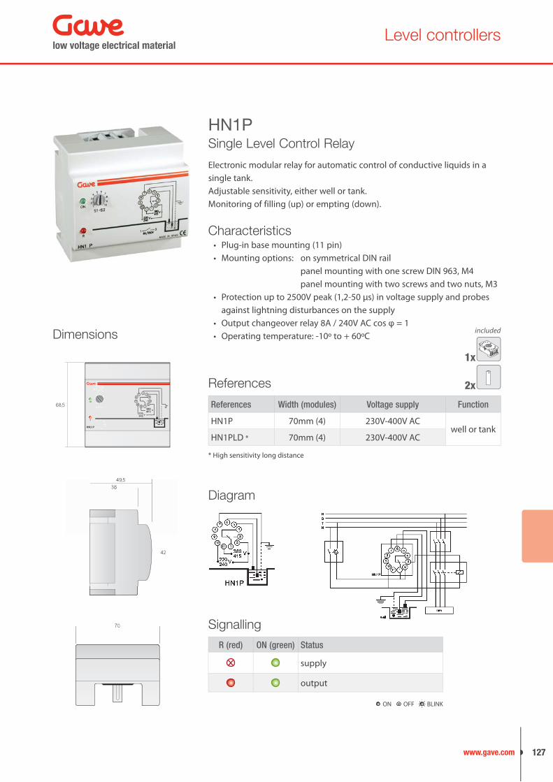
CharacteristicsPlug-in base mounting (11 pin)• Mounting options: on symmetrical DIN rail•
panel mounting with one screw DIN 963, M4 panel mounting with two screws and two nuts, M3
Protection up to 2500V peak (1,2-50 μs) in voltage supply and probes • against lightning disturbances on the supplyOutput changeover relay 8A / 240V AC cos φ = 1• Operating temperature: -10º to + 60ºC•
Single Level Control Relay
Electronic modular relay for automatic control of conductive liquids in a single tank.Adjustable sensitivity, either well or tank.Monitoring of filling (up) or empting (down).
HN1P
Diagram
Dimensions
HN1 P
ON
R
A BC
D
EF
8 10
66
0,124
max. time
modesd
1s 10s1m
10m
1h10h
68,5
49,538
42
49,538
42
7070
1x
2x
included
References Width (modules) Voltage supply Function
HN1P 70mm (4) 230V-400V ACwell or tank
HN1PLD * 70mm (4) 230V-400V AC
References
* High sensitivity long distance
Signalling
R (red) ON (green) Status
supply
output
ON OFF BLINK
low voltage electrical material
127www.gave.com

CharacteristicsPlug-in base mounting (11 pin)• Mounting options: on symmetrical DIN rail•
panel mounting with one screw DIN 963, M4 panel mounting with two screws and two nuts, M3
Protection up to 2500V peak (1,2-50 μs) in voltage supply and probes • against lightning disturbances on the supplyOutput changeover relay 8A / 240V AC cos φ = 1• Operating temperature: -10º to + 60ºC•
Double Level Control Relay
Electronic relay for the automatic control of conductive liquids in two different tanks.Two independent adjustable sensitivities, for well and tank.Monitoring filling (up) or empting (down).Both functions combined for monitoring the pumping out of a welland filling of a tank.
HN2P
Diagram
References Width (modules) Voltage supply Function
HN2P 70mm (4) 230V-400V AC well and tank
References
Dimensions
HN2 P
ON
R
68,5
HN2 P
ON
R
A BC
D
EF
8 10
66
0,124
max. time
modesd
1ss 10s0s101m
10m
1h10h
68,5
49,538
42
49,538
42
7070
1x
4x
included
Signalling
R (red) ON (green) Status
supply
output
ON OFF BLINK
Control relays and protection
low voltage electrical material128

Alternating relays
CharacteristicsReal changeover relay to alternate cyclically and to avoid short-cycling• When the device is receiving no external signal, both changeover • contacts will remain openMounting on symmetrical DIN rail• Output changeover relay 8A / 250V AC cos φ = 1• Output contacts (1,3,4,6) voltage free• Operating temperature: -10º to + 60ºC•
Alternating RelayElectronic relay designed to alternate 2 different outputs (pumps, compressors...) controlled by an external signal.Alternates cyclically between 2 outputs.
AR01
1 - 4
7 - 8
contacts
4 - 6
outputpump 1
signal
outputpump 2
Diagram
References Width (modules) Voltage supply
AR01 35mm (2) 220-240V / 380-415 V AC
AR01-24AC 35mm (2) 24 V AC
ReferencesDimensions
AR01
R1
1 32 4 65
7 98 10 1211
R2
modes
90
35
6049
26,1
45 68,6
SignallingConnection
R Status
relay on
relay off
ON OFF BLINK
low voltage electrical material
129www.gave.com

CharacteristicsReal changeover relay to alternate cyclically and to avoid short-cycling• When the device is receiving no external signal, both changeover • contacts will remain openMounting on symmetrical DIN rail• Output changeover relay 8A / 250V AC cos φ = 1• Output contacts (1,3,4,6) voltage free• Operating temperature: -10º to + 60ºC•
Simultaneous Alternating Relay
Electronic relay designed to alternate 2 different outputs (pumps, compressors...) controlled by an external signal.Alternates cyclically between 2 outputs.Possible operation of both outputs at the same time (simultaneous).
AR02
1 - 4
7 - 9
4 - 6
outputpump 1
signal
outputpump 2
7 - 8
contactssignal
Diagram
Connection
References Width (modules) Voltage supply
AR02 35mm (2) 220-240V / 380-415 V AC
AR02-24AC 35mm (2) 24 V AC
ReferencesDimensions
AR02
R1
1 32 4 65
7 98 10 1211
R2
modes
90
35
6049
26,1
45 68,6 Signalling
R Status
relay on
relay off
ON OFF BLINK
Control relays and protection
low voltage electrical material130

Alternating relays
Connection
CharacteristicsReal changeover relay to alternate cyclically and to avoid short-cycling• When the device is receiving no external signal, all changeover contacts • will remain openMounting on symmetrical DIN rail• Output changeover relay 8A / 250V AC cos φ = 1• Output contacts (1 to 6) voltage free• Operating temperature: -10º to + 60ºC•
Simultaneous Alternating Relay - 3 outputs
Electronic relay designed to alternate 3 different outputs (pumps, compressors...) controlled by an external signal.Alternates cyclically between 3 outputs.Possible operation of all 3 outputs at the same time (simultaneous).
AR03
R2
R1
P3
P2
P1
R3
Externalsignal
Relays
Diagram
References Width (modules) Voltage supply
AR03 35mm (2) 220-240V / 380-415 V AC
AR03-24AC 35mm (2) 24 V AC
ReferencesDimensions
AR03
1 32 4 65
7 98 10 1211
R1
R2
R3
modes
90
35
6049
26,1
45 68,6 Signalling
R Status
relay on
stand-by mode(no signal)
relay off
ON OFF BLINK
low voltage electrical material
131www.gave.com
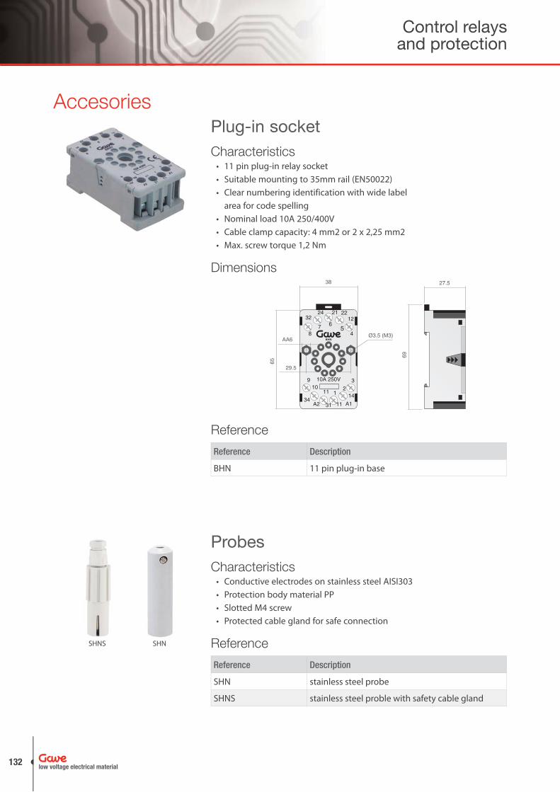
Accesories
Characteristics11 pin plug-in relay socket• Suitable mounting to 35mm rail (EN50022)• Clear numbering identification with wide label • area for code spellingNominal load 10A 250/400V• Cable clamp capacity: 4 mm2 or 2 x 2,25 mm2• Max. screw torque 1,2 Nm•
SHNS SHN
Plug-in socket
Probes
Reference Description
BHN 11 pin plug-in base
Reference
BHN
Dimensions
CharacteristicsConductive electrodes on stainless steel AISI303• Protection body material PP• Slotted M4 screw• Protected cable gland for safe connection•
Reference Description
SHN stainless steel probe
SHNS stainless steel proble with safety cable gland
Reference
Control relays and protection
low voltage electrical material132
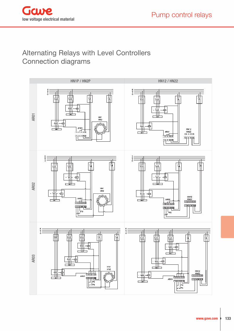
Pump control relays
Alternating Relays with Level ControllersConnection diagrams
HN1P / HN2P HN12 / HN22
AR01
AR02
AR03
low voltage electrical material
133www.gave.com
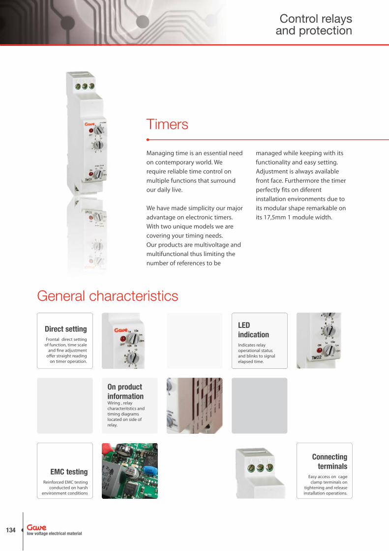
General characteristics
Direct settingFrontal direct setting
of function, time scale and fi ne adjustment
off er straight reading on timer operation.
LED indicationIndicates relay operational status and blinks to signal elapsed time.
On product informationWiring , relay characteritstics and timing diagrams located on side of relay.
Connecting terminals
Easy access on cage clamp terminals on
tightening and release installation operations.
EMC testingReinforced EMC testing
conducted on harsh environment conditions
Timers
Managing time is an essential need on contemporary world. We require reliable time control on multiple functions that surround our daily live.
We have made simplicity our major advantage on electronic timers. With two unique models we are covering your timing needs.Our products are multivoltage and multifunctional thus limiting the number of references to be
managed while keeping with its functionality and easy setting. Adjustment is always available front face. Furthermore the timer perfectly fits on diferent installation environments due to its modular shape remarkable on its 17,5mm 1 module width.
eneeral cchhara
Control relays and protection
low voltage electrical material134

Timers overview
SimplicityTimer rotary potentiometers accessible on the front face, easy setting with direct reading.
AccuracyAdvanced mechanics know-how is applied on frontal rotary switches that are produced with specific plastics particularly resistant to temperature changes. Consequently we minimise setting tolerances thus achieving high accuracy.
ControlIndependent Start input contact enlarges number of timer possible operations and associated control functionalities.
SafetyBoard insulation distances have been set above standard requirements preventing arcing and increasing operational safety.
SignallingOn/Off led indication on the front face informs about relay status, blinking led indicates elapsed time and forecasts relay changeover operation.
ApplicationsLighting controls• Ventilation• Access control• Automation process• Machinery• Commercial lights• Buzzer alarms• Machinery•
Timers have been developed to withstand harsh conditions following electrical endurance and climatic testing. EMC testing has been conducted above standard levels in order to guarantee positive operation on electromagnetic polluted environments safeguarding time control functionality.
FirmwareLarge flexibility on control specific requirements by integrating programable EEPROM memory. Customised products to particular market and OEM needs.
low voltage electrical material
135www.gave.com

CharacteristicsWorking temperature: -10º + 55ºC• Supply: 24-230V AC, 50/60Hz - 24V DC• Power consumption: 1,7W / 3VA• Output changeover relay AC1:•
5A, 250V DC1: 5A, 24V AC15: 3A, 250V DC13: 2A, 24V
AssemblyMounting on symmetrical DIN rail• Connection with protected wire clamps•
Signalling2 indicating LED for ouput relay and operation status• Elapsed time indication by blinking LED•
Time ranges 1S from 0,1 sec. to 1 sec. 10S from 1 sec. to 10 sec. 1M from 0,1 min. to 1 min. 10M from 1 min. to 10 min. 1HOUR from 10 min. to 1 hour 10HOURS from 1 hour to 10 hours
Multifunctional Timer
Multi-voltage and multi-function timer with four basic operational functions and six selectable time ranges by frontal rotary selector.
TM01
References Width (modules) Voltage supply
TM01 17,5mm (1) 24-230V AC / 24V DC
TM01-12DC 17,5mm (1) 12V DC
TM01-DC 17,5mm (1) 127V DC ± 20%
References
Dimensions
TM01
OFF
4 5 6
ON
A BC
D
EF
8 10
6
0,124
max. time
modes
1s 10s1m
10m
1h10h
1 2 3
90
5443
20,4
45 68,6
17,5
Control relays and protection
low voltage electrical material136

Multifunctional timers
On delaySupply voltage is on. Set delay time starts when “Start” signal is on. Output relay energizes after the timing period. Reset to zero occurs when disconnecting supply or after a new “Start” connection when the time cycle is finished.
Interval timerSupply voltage is on. When connecting “Start” the output relay energizes, after the timing period output relay de-energizes. Reset to zero occurs when disconnecting supply or after a new “Start” connection when the time cycle is finished.
Interval on Make/BreakSupply voltage is on. When making or breaking “Start” output relay energises until set time is reached. Any signal change in “Start” will reset timing to zero.
Off DelaySupply voltage is on. When connecting “Start” output relay energises. When “Start” breaks timing period will start. At the end of timing period output relay will de-energize. When “Start” breaking occurs during timing period timer ill reset timing to zero.
Equal cycling, OFF cycle firstSupply voltage is on. When making “Start” the output remains de-energized during the set timing period. A cyclic mode does continue with energizing and de-energizing periods according to the set time. Timer will reset to zero when supply is removed.
Equal cycling, ON cycle firstSupply voltage is on. When making “Start” the output relay will energize during the set timing period. A cyclic mode does continue with de-energizing and energiznig periods according to the set timing. Timer will reset to zero when supply is removed.
Operational functions
supply
signal
output
timing
supply
signal
output
timing
supply
signal
output
timing
supply
signal
output
timing
supply
signal
output
timing
supply
signal
output
timing
low voltage electrical material
137www.gave.com

CharacteristicsWorking temperature: -10º + 55ºC• Supply: 24-230V AC, 50/60Hz - 24V DC• Power consumption: 1,7W / 3VA• Output changeover relay AC1: 5A, 250V•
DC1: 5A, 24V AC15: 3A, 250V DC13: 2A, 24V
Time ranges 1S from 0,1 sec. to 1 sec. 10S from 1 sec. to 10 sec. 1M from 0,1 min. to 1 min. 10M from 1 min. to 10 min. 1HOUR from 10 min. to 1 hour 10HOURS from 1 hour to 10 hours
Cycling TimerMulti-voltage and multi-function timer with three operating modes by lateral DIP and six time ranges by frontal rotary selector.
TM02
References Width (modules) Voltage supply
TM02 17,5mm (1) 24-230V AC / 24V DC
TM02-12DC 17,5mm (1) 12V DC
References
Dimensions
Operational functions
Function Modes
Function A: Asymmetrical re-cycling, OFF cycle firstWhen supply voltage is on, set delay time (T1) starts. Output relay energizes when reaches T1 then starts the 2nd timing. Output relay (T2) de-energizes after the timing period the cycle re-starts. T1 and T2 are regulated independently. Timer will reset to zero when supply is removed.
supply
output
timing
Function B: Asymmetrical re-cycling, ON cycle firstWhen supply voltage is on set delay time starts the 1st timing period, otuput is energized. When the time cycle (T1) is finished output relay T2 energizes and starts the 2nd timing period. When the time cycle (T2) is finished the cycle re-starts. T1 and T2 are regulated independently. Timer will reset to zero when supply is removed.
supply
output
timing
Function C: Asymmetrical cycling, OFF/ONWhen supply voltage is on the 1st timing period (T1) starts. After finishing the first period output relay energizes and the 2nd timing period (T2) starts. After finishing the second period output relay de-energizes until the supply is removed.
supply
output
timing
Function A: Asymmetrical re-cycling, OFF cycle first
Function B: Asymmetrical re-cycling, ON cycle first
Function C: Asymmetrical cycling, OFF/ON
TM02
OFF
4 5 6
ON
A BC
D
EF
8 10
6
0,124
8 10
6
0,124
1s 10s1m
10m
1h10h
1 2 3
90
5443
20,4
45 68,6
17,5
Control relays and protection
low voltage electrical material138

Star-Delta timers
CharacteristicsStar-delta timer• 2 output relay 1 pole changeover contacts• Transition delay time adjustable from 20to 300 ms.• Star time delay adjustable from 6 to 60s• Led indicator for relay transition• Energizing at the end of time delay• Compact width 17,5 mm 1 module• Mounting on symmetrical DIN rail• Consumption: 3 VA• Switching capacity: AC1: 5A / 250V AC15: 3A / 250V•
DC1: 5A / 24V DC13: 2A / 24V
Star Delta timersModular star delta timer are an ideal solution on those start up motor applications where we need a modular space saving timer with time adjustment.
TMETR
References Width (modules) Voltage supply
TMETR 17,5mm (1) 230V AC / 24 AC/DC
References
Dimensions Diagram
U
R
1815
16
2825
26
Time
TimeTransfer
L +24VAC/VDC
8A250VAC
8A250VAC
25 26 2815 16 18A2
A1 A3
N --
240VAC
ConnectionRU
TMETR
98
6017,5
64
t (s)
t (ms)
6
15
30
45
60
20
80
150
230
300
low voltage electrical material
139www.gave.com
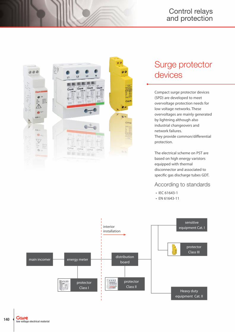
Compact surge protector devices (SPD) are developed to meet overvoltage protection needs for low voltage networks. These overvoltages are mainly generated by lightning although also industrial changeovers and network failures. They provide common/differential protection.
The electrical scheme on PST are based on high energy varistors equipped with thermal disconnector and associated to specific gas discharge tubes GDT.
According to standards • IEC 61643-1 • EN 61643-11
Surge protector devices
sensitive equipment Cat. I
Heavy duty equipment Cat. II
main incomerdistribution
board
protectorClass II
protectorClass I
energy meter
interior installation
protectorClass III
Control relays and protection
low voltage electrical material140
Surge protector devices
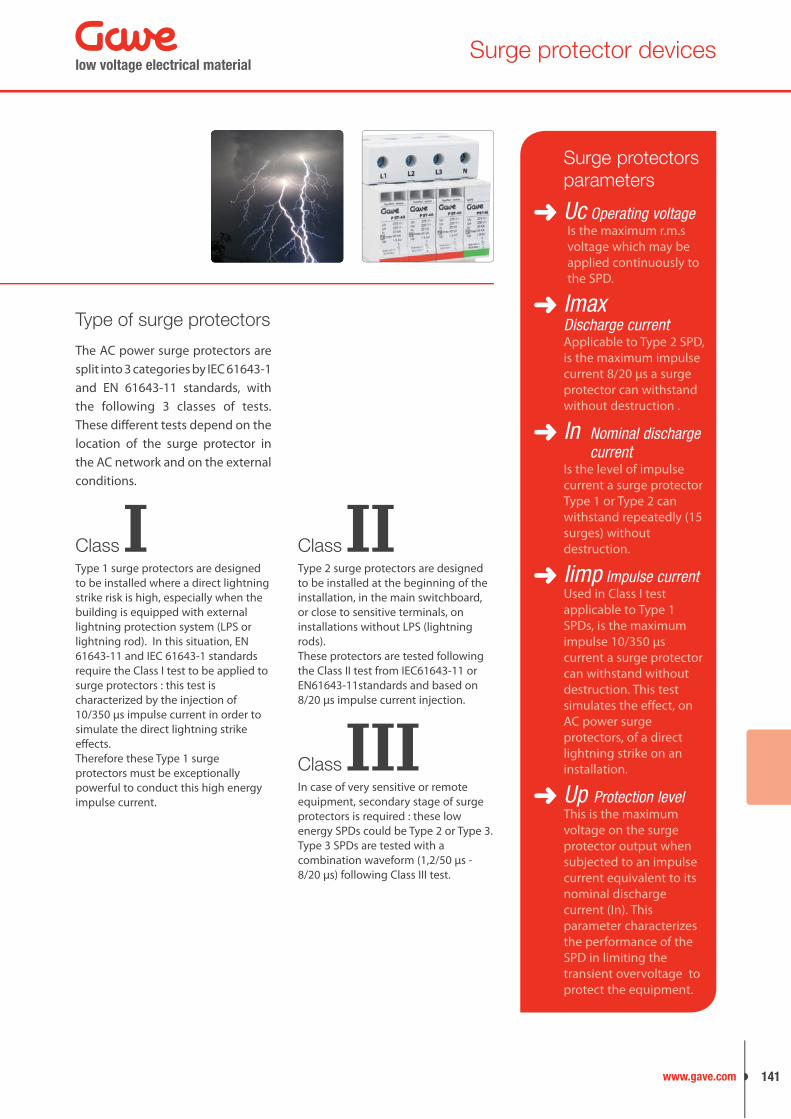
The AC power surge protectors are split into 3 categories by IEC 61643-1 and EN 61643-11 standards, with the following 3 classes of tests. These different tests depend on the location of the surge protector in the AC network and on the external conditions.
Type of surge protectors
Surge protectors parameters
Uc Operating voltageIs the maximum r.m.s voltage which may be applied continuously to the SPD.
Imax Discharge current
Applicable to Type 2 SPD, is the maximum impulse current 8/20 μs a surge protector can withstand without destruction .
In Nominal discharge current
Is the level of impulse current a surge protector Type 1 or Type 2 can withstand repeatedly (15 surges) without destruction.
Iimp Impulse currentUsed in Class I test applicable to Type 1 SPDs, is the maximum impulse 10/350 μs current a surge protector can withstand without destruction. This test simulates the effect, on AC power surge protectors, of a direct lightning strike on an installation.
Up Protection levelThis is the maximum voltage on the surge protector output when subjected to an impulse current equivalent to its nominal discharge current (In). This parameter characterizes the performance of the SPD in limiting the transient overvoltage to protect the equipment.
Type 1 surge protectors are designed to be installed where a direct lightning strike risk is high, especially when the building is equipped with external lightning protection system (LPS or lightning rod). In this situation, EN 61643-11 and IEC 61643-1 standards require the Class I test to be applied to surge protectors : this test is characterized by the injection of 10/350 μs impulse current in order to simulate the direct lightning strike effects. Therefore these Type 1 surge protectors must be exceptionally powerful to conduct this high energy impulse current.
ClassIType 2 surge protectors are designed to be installed at the beginning of the installation, in the main switchboard, or close to sensitive terminals, on installations without LPS (lightning rods). These protectors are tested following the Class II test from IEC61643-11 or EN61643-11standards and based on 8/20 μs impulse current injection.
IIClass
In case of very sensitive or remote equipment, secondary stage of surge protectors is required : these low energy SPDs could be Type 2 or Type 3.Type 3 SPDs are tested with a combination waveform (1,2/50 μs - 8/20 μs) following Class III test.
IIIClass
low voltage electrical material
141www.gave.com

Protector Advanced Technology
Operating principle
PST surge protectors are based on zinc metal-oxide varistors (MOV), the best compromise between a fast response time (<25 ns) and a high discharge current capacity, which are the main parameters to provide effi cient protection.Surge protection is highly improved by combining varistors with a specifi c gas discharge tubes (GDT).
Improved performance is specifi cally attested in;
protection level (Up)• life duration (due to the • supression of leakage current)continuous operation and • power quality (no follow current)
V : VaristorFt : Thermal fuset˚ : Thermal disconnectionC : Remote signaling contact
Nevertheless the end of life of these varistors must be absolutely monitored thus requiring the systematic use of built-in thermal disconnection devices.
Disconnection devices
Internal thermal ▪ security which will disconnect the surge protector from the AC network in case of thermal runaway. In such a case, the user will be warned about the trouble by an indicator (mechanical or light) in front of the protector and will carry out the replacement of the defective SPD.
External electrical • disconnection (fuses or breaker) to disconnect the surge protector from the AC network in case of internal short circuit, e.g. due to an excessive impulse current.
In compliance with the standards, the AC power surge protectors are equipped with external and internal disconnection devices in order to provide total safety in case of failure.2 types of disconnection devices are necessary:
Control relays and protection
low voltage electrical material142
Surge protector devices
Common and Differential mode protection
Choosing disconnection devices
Fuses provide a more suitable solution as short circuit protection for SPD
parameters fuses circuit breaker
Voltage decrease (Up improvement) +Lightning impulse current behaviour + -
contacts wear
Icc + -
Reduced dimensions -fuses > 25A +
Cost + -
Class I Class II
15 kA (10/350)
15kA(8/20)
40kA(8/20)
Icc = 300A up to 1kA 25A 16A 16A
Icc = 1kA up to 7kA 50A 16A 25A
Icc = 7kA and above 63A 25-40A 50A
The rating of the external fuses (or breaker) are in relation with the discharge capability of the SPD and the prospective short-circuit current of the installation.
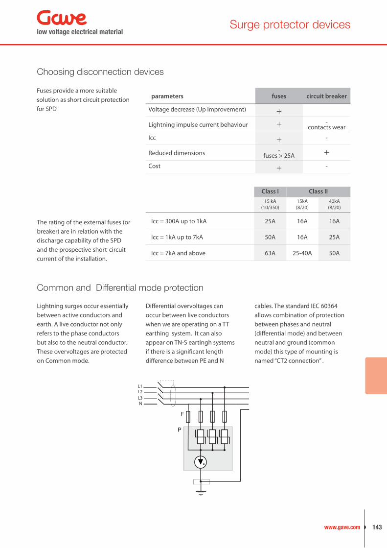
Lightning surges occur essentially between active conductors and earth. A live conductor not only refers to the phase conductors but also to the neutral conductor. These overvoltages are protected on Common mode.
F
P
L1L2L3N
Diff erential overvoltages can occur between live conductors when we are operating on a TT earthing system. It can also appear on TN-S eartingh systems if there is a signifi cant length diff erence between PE and N
cables. The standard IEC 60364 allows combination of protection between phases and neutral (diff erential mode) and between neutral and ground (common mode) this type of mounting is named “CT2 connection” .
low voltage electrical material
143www.gave.com
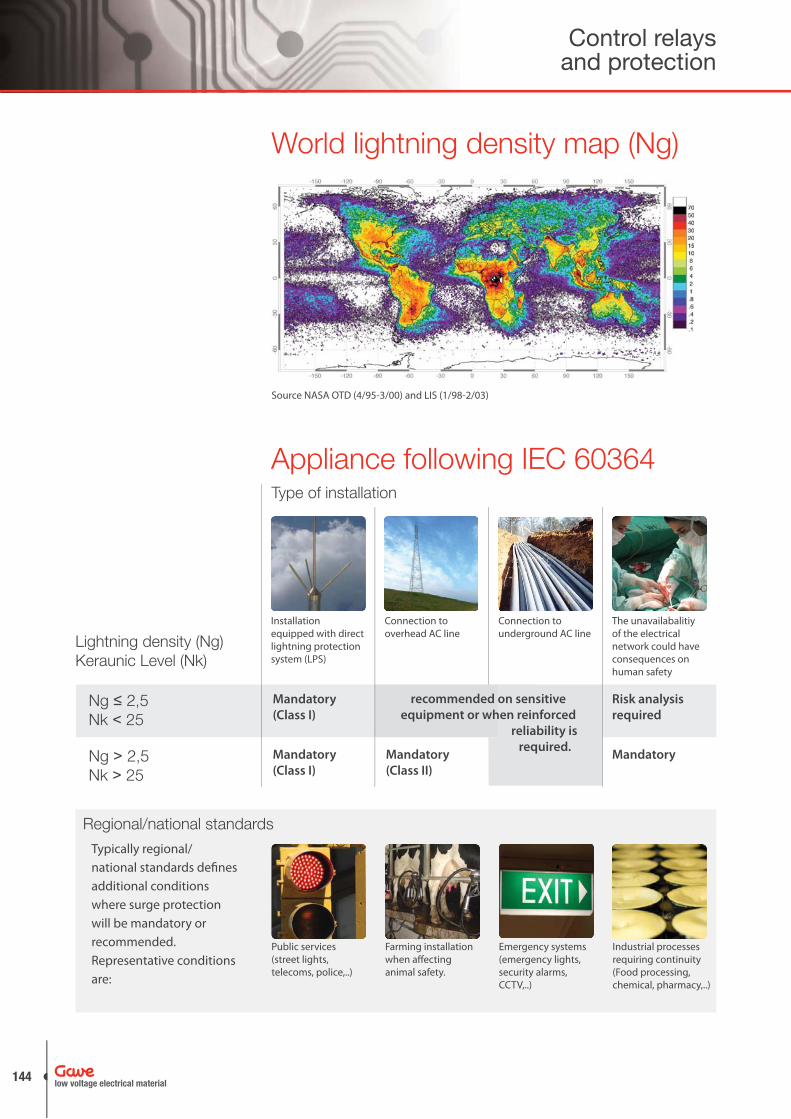
Appliance following IEC 60364
Regional/national standards
Installation equipped with direct lightning protection system (LPS)
Public services (street lights, telecoms, police,..)
Ng ≤ 2,5Nk < 25
Ng > 2,5Nk > 25
Connection to overhead AC line
Farming installation when aff ecting animal safety.
Connection to underground AC line
Emergency systems (emergency lights, security alarms, CCTV,..)
The unavailabalitiy of the electrical network could have consequences on human safety
Industrial processes requiring continuity (Food processing, chemical, pharmacy,..)
Mandatory
(Class I)
Risk analysis
required
Mandatory
(Class I)
Mandatory
(Class II)
Mandatory
Lightning density (Ng)Keraunic Level (Nk)
Type of installation
Source NASA OTD (4/95-3/00) and LIS (1/98-2/03)
World lightning density map (Ng)
recommended on sensitive
equipment or when reinforced
reliability is
required.
Typically regional/national standards defi nes additional conditions where surge protection will be mandatory or recommended.Representative conditions are:
Control relays and protection
low voltage electrical material144
Surge protector devices
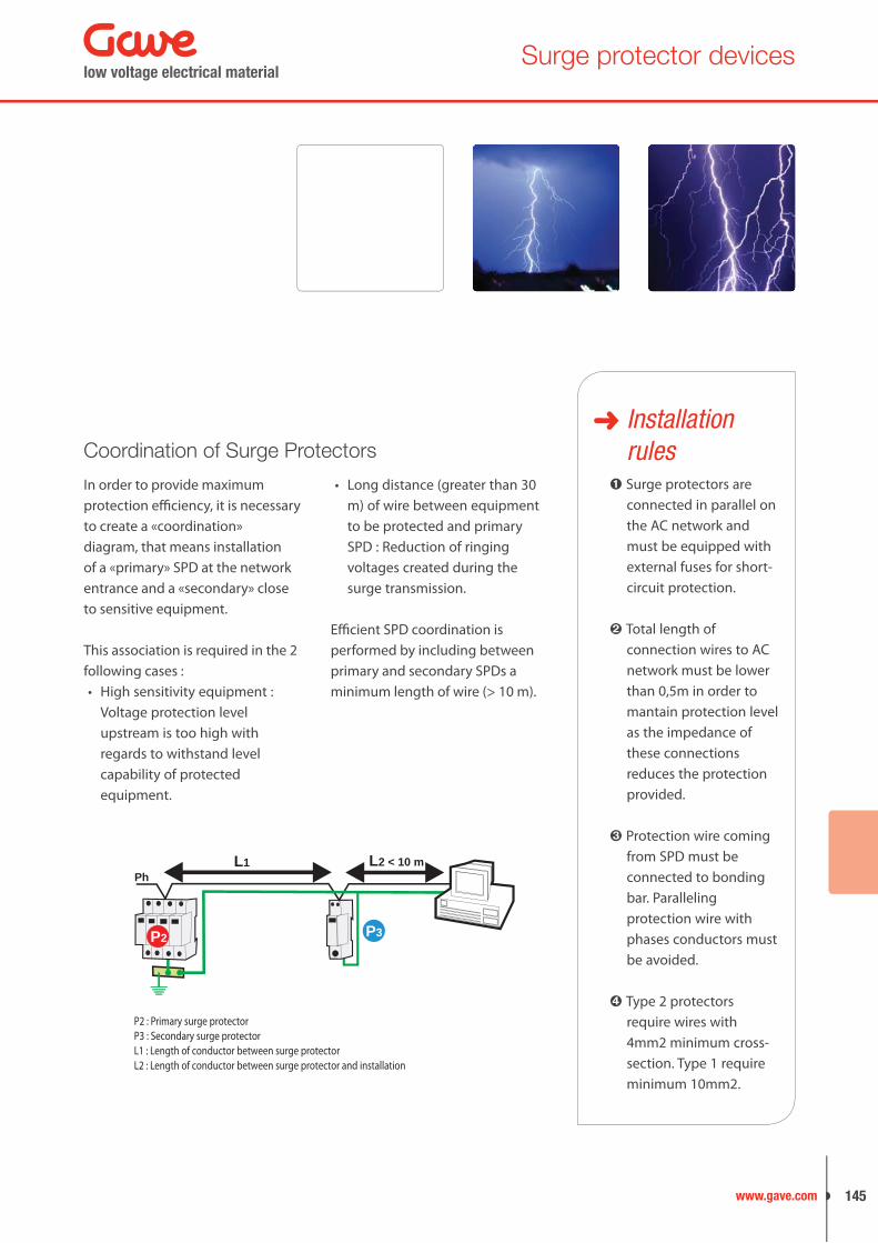
Coordination of Surge Protectors
In order to provide maximum protection effi ciency, it is necessary to create a «coordination» diagram, that means installation of a «primary» SPD at the network entrance and a «secondary» close to sensitive equipment.
This association is required in the 2 following cases :
High sensitivity equipment : • Voltage protection level upstream is too high with regards to withstand level capability of protected equipment.
Long distance (greater than 30 • m) of wire between equipment to be protected and primary SPD : Reduction of ringing voltages created during the surge transmission.
Effi cient SPD coordination is performed by including between primary and secondary SPDs a minimum length of wire (> 10 m).
Installation rules
Surge protectors are connected in parallel on the AC network and must be equipped with external fuses for short-circuit protection.
Total length of connection wires to AC network must be lower than 0,5m in order to mantain protection level as the impedance of these connections reduces the protection provided.
Protection wire coming from SPD must be connected to bonding bar. Paralleling protection wire with phases conductors must be avoided.
Type 2 protectors require wires with 4mm2 minimum cross-section. Type 1 require minimum 10mm2.
P2 : Primary surge protector
L1 : Length of conductor between surge protectorL2 : Length of conductor between surge protector and installation
L1Ph
P3
L2 < 10 m
P2
P3 : Secondary surge protector
low voltage electrical material
145www.gave.com
Surge protector devices
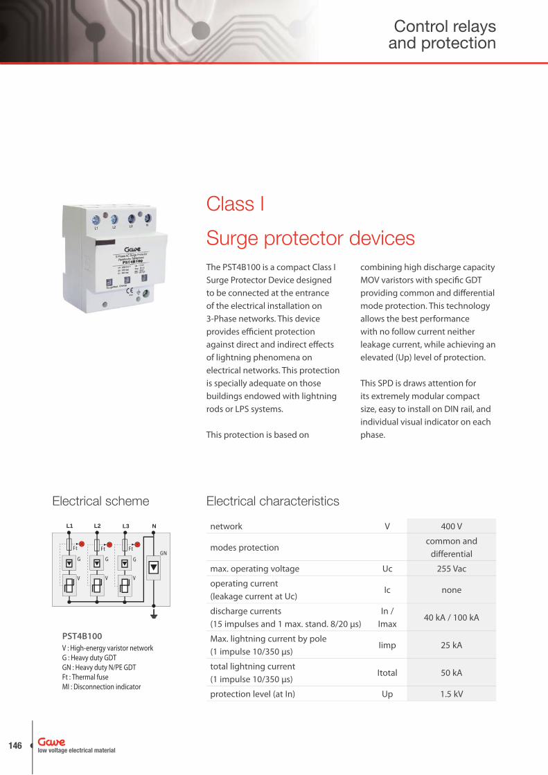
Class I
The PST4B100 is a compact Class I Surge Protector Device designed to be connected at the entrance of the electrical installation on 3-Phase networks. This device provides effi cient protection against direct and indirect eff ects of lightning phenomena on electrical networks. This protection is specially adequate on those buildings endowed with lightning rods or LPS systems.
This protection is based on
combining high discharge capacity MOV varistors with specifi c GDT providing common and diff erential mode protection. This technology allows the best performance with no follow current neither leakage current, while achieving an elevated (Up) level of protection.
This SPD is draws attention for its extremely modular compact size, easy to install on DIN rail, and individual visual indicator on each phase.
Electrical characteristics
network V 400 V
modes protectioncommon and
differential
max. operating voltage Uc 255 Vac
operating current (leakage current at Uc)
Ic none
discharge currents(15 impulses and 1 max. stand. 8/20 μs)
In / Imax
40 kA / 100 kA
Max. lightning current by pole(1 impulse 10/350 μs)
Iimp 25 kA
total lightning current(1 impulse 10/350 μs)
Itotal 50 kA
protection level (at In) Up 1.5 kV
Electrical scheme
Ft Ft Ft
L1
V
G
L2
V
G
L3
V
G
N
GN
PST4B100
V : High-energy varistor networkG : Heavy duty GDTGN : Heavy duty N/PE GDTFt : Thermal fuseMI : Disconnection indicator
Control relays and protection
low voltage electrical material146
Surge protector devices
Dimensions67
90
70
L1 L2 L3 Nextra compact size (up to 50% space saving)
70
110-140
dimensions see diagram
Connectionby screw terminals:
6-35 mm2
Disconnection indicator red light indicators
Remote signaling of disconnection none
Mounting symmetrical rail 35 mm
Operating temperature -40/ +85º C
Protection class IP20
Housing material Thermoplastic UL94-V0
Standards compliance
IEC 61643-1 InternationalLow Voltage SPD
Test Class I
EN 61643-11 EuropeLow Voltage SPD
Test Class I
Mechanical characteristics
COMPACT SIZE
FF FFN
L2L1
L3
PE
Ground
Main swichtboard
Installation scheme
low voltage electrical material
147www.gave.com

Surge Protector DevicesClass II
Surge protector devices are developed to meet overvoltage protection needs transmitted on low voltage networks. These overvoltages are mainly generated by atmospheric lightening although also might occur due to industrial changeovers and network failures.
Surge dischargers provide common/differential protection.
The electrical schemes on PST protectors combines high energy MOV varistor with an specific gas discharge tube GDT thus obtaining
high performance protection characteristics.
Surge protectors PST are built with plug-in modules with failure indicator and a monobloc fix DIN rail base which allows an easy and fast replacement on maintenance operations.
According to standardsIEC 61643-1•
EN 61643-11•
UL1449 ed. 2•
Control relays and protection
low voltage electrical material148

Surge protector devices
General characteristics
Visual indicatorGreen colour indicates correct operation and red colour indicates module replacement.
Modules easy replacementPlug-in modules easy and quick to replace at the end of protection life.
Modular constructionDesigned to fi t on modular enclosures with frontal 45mm window and 17,5mm. modules.
Remote signallingOperational status on the protection is constantly supervised by fl oating changeover contact that will activiate if module changes status.
DIN rail mountingDirect mounting on symmetrical DIN rail acc. to EN 60715
Mechanical codingPlug-in modules and modular bases are mechanically coded and prevent wrong module replacement.
i
MarkingTerminals clearly marked for easy wiring. Modules marked with reference and electrical data.
low voltage electrical material
149www.gave.com
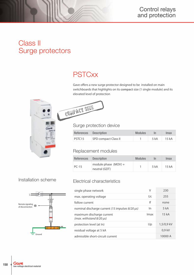
Gave offers a new surge protector designed to be installed on main switchboards that highlights on its compact size (1 single module) and its elevated level of protection
COMPACT SIZE
single phase network V 230
max. operating voltage Uc 255
follow current If none
nominal discharge current (15 impulses 8/20 μs) In 5 kA
maximum discharge current(max. withstand 8/20 μs)
Imax 15 kA
protection level (at In) Up 1,5/0,9 kV
residual voltage at 5 kA 0,9 kV
admissible short-circuit current 10000 A
Electrical characteristics
Surge protectorsClass II
PSTCxx
Installation scheme
PE
F F
NL
Remote signalingof disconnection
Ground
References Description Modules In Imax
PSTC15 SPD compact Class II 1 5 kA 15 kA
Surge protection device
References Description Modules In Imax
PC-15module phase (MOV) + neutral (GDT)
1 5 kA 15 kA
Replacement modules
Control relays and protection
low voltage electrical material150
Surge protector devices
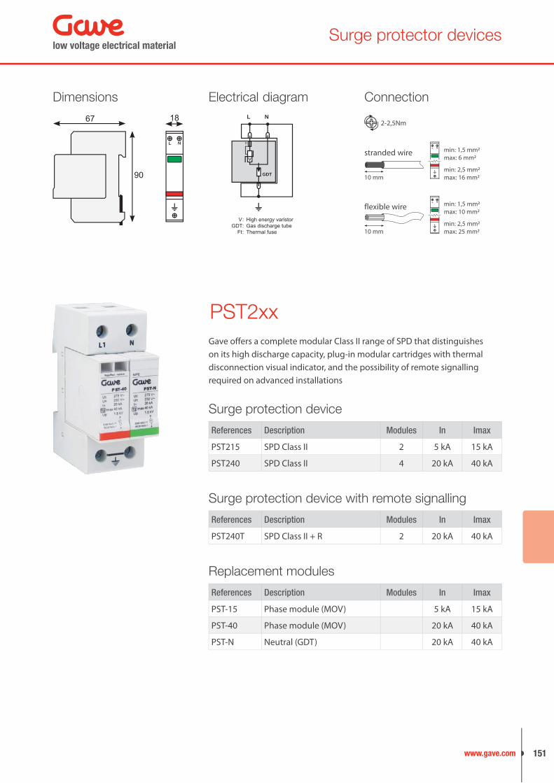
L N
67 18
90
Dimensions Electrical diagram
V : High energy varistor GDT : Gas discharge tube Ft : Thermal fuse
L
GDT
Ft
N
V
PST2xx
Connection
stranded wire
flexible wire
Gave offers a complete modular Class II range of SPD that distinguishes on its high discharge capacity, plug-in modular cartridges with thermal disconnection visual indicator, and the possibility of remote signalling required on advanced installations
2-2,5Nm
10 mm
10 mm
min: 1,5 mm2max: 6 mm2
L N
min: 1,5 mm2max: 10 mm2
L N
min: 2,5 mm2max: 16 mm2
min: 2,5 mm2max: 25 mm2
References Description Modules In Imax
PST215 SPD Class II 2 5 kA 15 kA
PST240 SPD Class II 4 20 kA 40 kA
Surge protection device
References Description Modules In Imax
PST240T SPD Class II + R 2 20 kA 40 kA
Surge protection device with remote signalling
References Description Modules In Imax
PST-15 Phase module (MOV) 5 kA 15 kA
PST-40 Phase module (MOV) 20 kA 40 kA
PST-N Neutral (GDT) 20 kA 40 kA
Replacement modules
low voltage electrical material
151www.gave.com
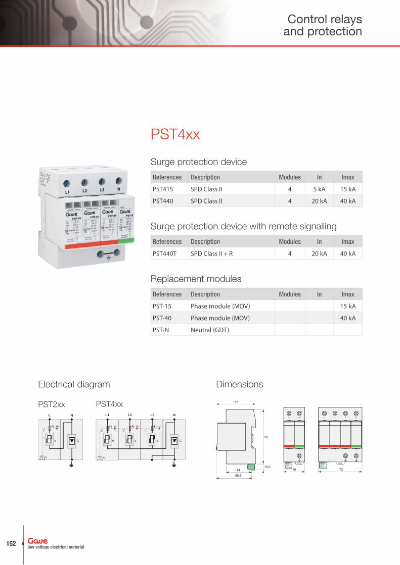
PST4xx
72
L L L N
90
10.6
67
44
60.8
36
L N
DimensionsElectrical diagram
NL
V G
C
Ft MI
t°
PST2xxL1 L2 L3 N
V G
Ft MI
t°
V
Ft MI
t°
V
C
Ft MI
t°
PST4xx
References Description Modules In Imax
PST415 SPD Class II 4 5 kA 15 kA
PST440 SPD Class II 4 20 kA 40 kA
Surge protection device
References Description Modules In Imax
PST440T SPD Class II + R 4 20 kA 40 kA
Surge protection device with remote signalling
References Description Modules In Imax
PST-15 Phase module (MOV) 15 kA
PST-40 Phase module (MOV) 40 kA
PST-N Neutral (GDT)
Replacement modules
Control relays and protection
low voltage electrical material152

Surge protector devices
Electrical characteristics
PST2xx PST4xxPST215 PST240 PST240T PST415 PST440 PST440T
network V 230 230 230 230/400 230/400 230/400
max. operating voltage. Uc 275 V~ 275 V~ 275 V~ 275 V~ 275 V~ 275 V~
follow current If none none none none none none
nominal discharge current15 x 8/20 μs impulses In 5 kA 20 kA 20 kA 5 kA 20 kA 20 kA
maximum discharge current Imax 15 kA 40 kA 40 kA 15 kA 40 kA 40 kA
protection level N/PE(at In) Up 1,5 kV 1,5 kV 1,5 kV 1,5 kV 1,5 kV 1,5 kV
protection level L/N (at In) Up 0,9 kV 1,25 kV 1,25 kV 0,9 kV 1,25 kV 1,25 kV
residual voltage at 5kA 0,9 kV 0,9 kV 0,9 kV 0,9 kV 0,9 kV 0,9 kV
protection modes common • • • • • •
differential • • • • • •
remote signalling - - • - - •
Connection
Installation scheme
PST2xx PST4xx
Remote indication
Min: 12 V DC, 10 mAMax: 250 V AC, 1 A
111412
in watch
111412
default
min: 2,5 mm2max: 16 mm2
min: 2,5 mm2max: 25 mm2
stranded wire
flexible wire
2-2,5Nm
10 mm
10 mm
PE
F F
Ground
Main switchboard
NL3
L1L2
Remote signallingof disconnection PE
F F F F
NL3
L1L2
Remote signallingof disconnection
Ground
Main switchboard
low voltage electrical material
153www.gave.com
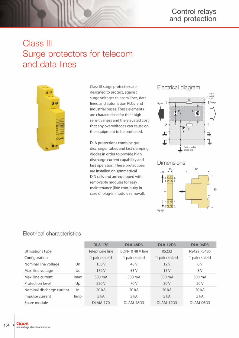
Surge protectors for telecom and data lines
Class III surge protectors are designed to protect, against surge voltages telecom lines, data lines, and automation PLCs and industrial buses. These elements are characterised for their high sensitiveness and the elevated cost that any overvoltages can cause on the equipment to be protected.
DLA protections combine gas discharger tubes and fast clamping diodes in order to provide high discharge current capability and fast operation. These protections are installed on symmetrical DIN rails and are equipped with removable modules for easy maintenance (line continuity in case of plug-in module removal).
Class III
R
R
DP
1
2
1
2PB
EquiptLigne
Earth possible on rail DIN
Plug-inmoduleDLAM
Electrical diagram
90
65
1 2
1 2
13Line
Equipt
Dimensions
Electrical characteristics
DLA-170 DLA-48D3 DLA-12D3 DLA-06D3
Utilisations type Telephone line ISDN-T0 48 V line RS232 RS422 RS485
Configuration 1 pair+shield 1 pair+shield 1 pair+shield 1 pair+shield
Nominal line voltage Un 150 V 48 V 12 V 6 V
Max. line voltage Uc 170 V 53 V 15 V 8 V
Max. line current Imax 300 mA 300 mA 300 mA 300 mA
Protection level Up 220 V 70 V 30 V 20 V
Nominal discharge current In 20 kA 20 kA 20 kA 20 kA
Impulse current Iimp 5 kA 5 kA 5 kA 5 kA
Spare module DLAM-170 DLAM-48D3 DLAM-12D3 DLAM-06D3
Control relays and protection
low voltage electrical material154
Surge protector devices
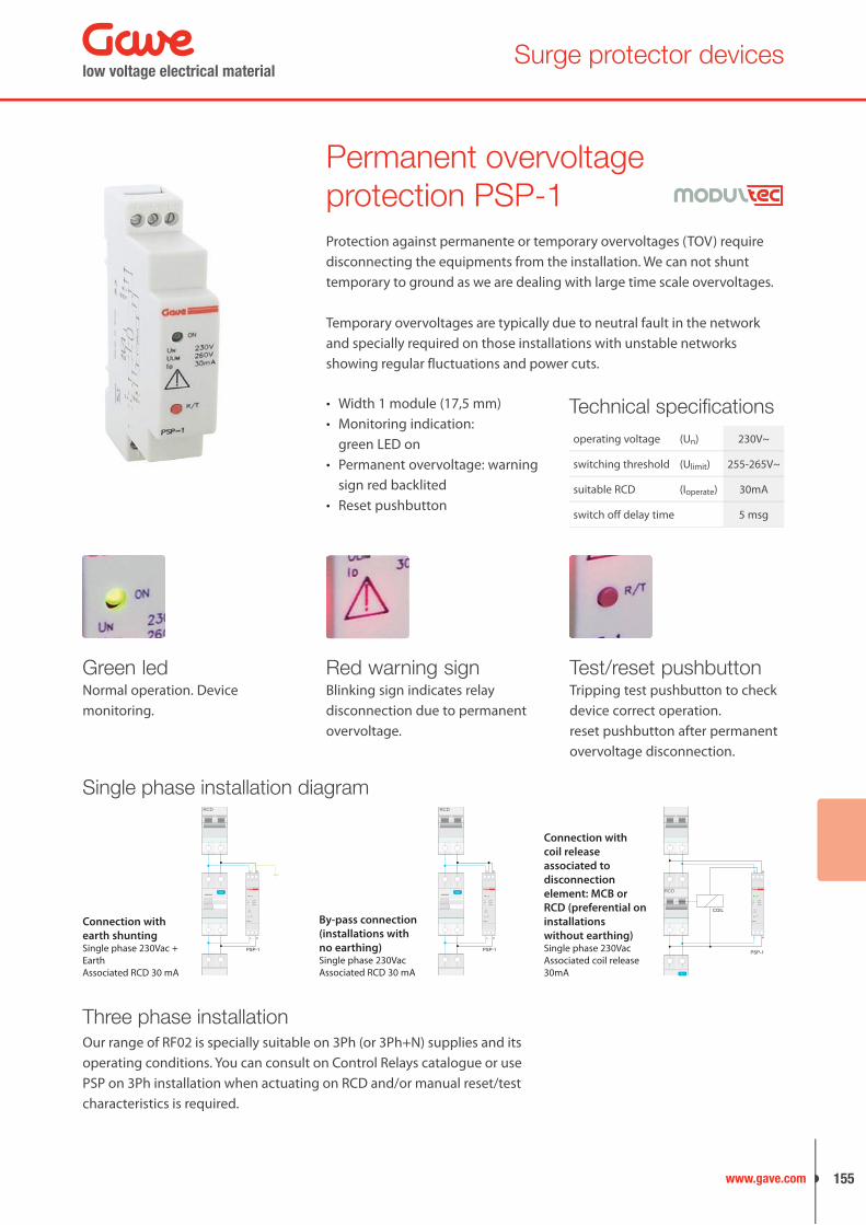
Green ledNormal operation. Device monitoring.
Red warning signBlinking sign indicates relay disconnection due to permanent overvoltage.
Test/reset pushbuttonTripping test pushbutton to check device correct operation.reset pushbutton after permanent overvoltage disconnection.
Width 1 module (17,5 mm)•
Monitoring indication:•
green LED onPermanent overvoltage: warning •
sign red backlitedReset pushbutton•
Technical specifi cationsoperating voltage (Un) 230V~
switching threshold (Ulimit) 255-265V~
suitable RCD (Ioperate) 30mA
switch off delay time 5 msg
Permanent overvoltage protection PSP-1
Single phase installation diagram
L N
PSP-1
ON
Io
R/T
Ulim
230V260V30mA
Un
!
PSP-1
L N
OFF 0
TEST
RCD
Connection with
earth shuntingSingle phase 230Vac + EarthAssociated RCD 30 mA
L N
PSP-1
ON
Io
R/T
Ulim
230V260V30mA
Un
!
PSP-1
L N
OFF 0
TEST
RCD
By-pass connection
(installations with
no earthing)Single phase 230VacAssociated RCD 30 mA
L N
PSP-1
ON
Io
R/T
Ulim
230V260V30mA
Un
!
PSP-1
COIL
L N
TEST
RCD
Connection with
coil release
associated to
disconnection
element: MCB or
RCD (preferential on
installations
without earthing)Single phase 230VacAssociated coil release 30mA
Three phase installation
Protection against permanente or temporary overvoltages (TOV) require disconnecting the equipments from the installation. We can not shunt temporary to ground as we are dealing with large time scale overvoltages.
Temporary overvoltages are typically due to neutral fault in the network and specially required on those installations with unstable networks showing regular fluctuations and power cuts.
Our range of RF02 is specially suitable on 3Ph (or 3Ph+N) supplies and its operating conditions. You can consult on Control Relays catalogue or use PSP on 3Ph installation when actuating on RCD and/or manual reset/test characteristics is required.
low voltage electrical material
155www.gave.com
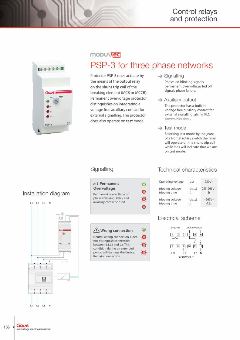
SignallingPhase led blinking signals permanent overvoltage, led off signals phase failure.
Axuiliary outputThe protector has a built in voltage free auxiliary contact for external signalling, alarm, PLC communication,..
Test modeSelecting test mode by the jeans of a frontal rotary switch the relay will operate on the shunt trip coil while leds will indicate that we are on test mode.
Technical characteristics
Operating voltage (Un) 230V~
tripping voltagetripping time
(Ulimit)(t)
255-265V~3s
tripping voltagetripping time
(Ulimit)(t)
>265V~0,8s
PSP-3 for three phase networks
L1
N
L2
N
L3 N
L3 NL1 L2
L1 L2 L3 N
COIL
OFF 0
PSP-3
1 32 4 65
7 98 10 1211
L1
L2
L3
ON TEST
21
2A/30Vdc
Installation diagram
Electrical scheme
L3 L2 N400V/50Hz
9 10 11 1287
654321
230V/50Hz/10A
L1
2A/30Vdc
! Wrong connection
Neutral wrong connection. Does not distinguish connection between L1,L2 and L3. This condition during an extended period will damage the device. Remake connection.
Permanent
Overvoltage
Permanent overvoltage on phases blinking. Relay and auxiliary contact closed..
Protector PSP-3 does actuate by the means of the output relay on the shunt trip coil of the breaking element (MCB or MCCB). Permanent overvoltage protector distinguishes on integrating a voltage free auxiliary contact for external signalling. The protector does also operate on test mode.
Signalling
Control relays and protection
low voltage electrical material156

Surge protector devices
Combining protections
Industrial, IT and services facilities face increasing demand on transient and temporary overvoltage protections in order to secure valuable equipments. Installation normative updates are improving equipment protection by writing down new requirements. Gave offers a complete range of combined solutions that warrant flexible installation and easy maintenance.
L1 L2 L3
L1 L2 L3 L4
rojo/red: replace
PST-40
Imax
Uc
T2
UpUn
In250V
1.5V230V
20kA40kA
EN61643-11 IEC61643-1
rojo/red: replace
PST-40
Imax
Uc
T2
UpUn
In250V
1.5V230V
20kA40kA
EN61643-11 IEC61643-1
rojo/red: replace
PST-40
Imax
Uc
T2
UpUn
In250V
1.5V230V
20kA40kA
EN61643-11 IEC61643-1
N/PE
PST-N
Imax
Uc
T2
Up
In400V
1.5V
20kA40kA
EN61643-11 IEC61643-1
PST4XX
N
L1
N
L2
N
L3 N
L3 NL1 L2
L1 L2 L3 N
COIL
OFF 0
PSP-3
1 32 4 65
7 98 10 1211
L1
L2
L3
ON TEST
21
2A/30Vdc
L N
L N
L N
PSP-1
ON
Io
R/T
Ulim
230V260V30mA
Un
!
PSP-1
L N
rojo/red: replace
PSTC15
Imax
Uc
T2
UpUn
In255V
1.5/0.9V230V
5kA15kA
EN61643-11 IEC61643-1
PSTC15
L N
RCD
OFF 0
TEST
MCB
L N
L N
L N
PSP-1
ON
Io
R/T
Ulim
230V260V30mA
Un
!
PSP-1
COIL
L N
rojo/red: replace
PSTC15
Imax
Uc
T2
UpUn
In255V
1.5/0.9V230V
5kA15kA
EN61643-11 IEC61643-1
L N
PST2XX
RCD
OFF 0
TEST
MCB
FlexibilityThe protector is installed upon space availability on the panel. Easy to place transient protection close to the earth connection.
Single phase installation Three phase installation
Remote signallingProtectors are equipped with remote signalling. We can distinguish if we have transient or temporary/permanent overvoltage condition.
MaintenanceFriendly maintenance. When a transient varistor protection ends its live we only need to replace this phase cartridge remaining other modules operative.
low voltage electrical material
157www.gave.com