CONTROL PANEL CA-64 - Lantech.huleiras.lantech.hu/leirasok/satel/ca64tele_eng.pdf · The Control...
41
CONTROL PANEL CA-64 (software version 1.03.xx) System description and installation. Przedsiębiorstwo Produkcyjno-Usługowe GDAŃSK ca64opis_e 06/01
Transcript of CONTROL PANEL CA-64 - Lantech.huleiras.lantech.hu/leirasok/satel/ca64tele_eng.pdf · The Control...

CONTROL PANEL
CA-64 (software version 1.03.xx)
System description and installation.
Przedsiębiorstwo Produkcyjno-Usługowe
GDAŃSK
ca64opis_e 06/01
INTRODUCTION
This manual relates to the main board of the alarm control panel, version CA64P v1.5, having been produced since October 2000.
Programming of all the CA-64 alarm system parameters is only possible by means of computer. The information applies to all versions of the control panel inclusive of the number 1.03.12 (the latest at the day when this manual was drawn up).
Detailed information that concerns programming parameters of the alarm system is available in the „Help” system of the DLOAD64 program purchased with the alarm control panel or alternatively, at the web site www.satel.pl. In order to avail oneself of the system you need to install and run the program. Next, highlight the desired element of the program window (to do so, move the mouse pointer to and click the left mouse key on the element) and then press the F1 key on the computer keyboard. Another way of getting access to the “Help” is to open the “Information” drop-down menu and select the “Help” function.
GENERAL FEATURES OF CONTROL PANEL
The Control panel CA-64 is designed for medium-sized and larger objects. Due to the possibility of development by adding the modules, it is ideal for objects, which are intended to be expanded. Possibility of connecting a big number of keypads (theoretically 64 + 18, including the keypads at the computer screen), possibility to define a big number of partitions and a big number of control zones allow to create reasonable solutions of protection in most objects. The control panel features many interesting properties that are its strong advantages in competition with other equipment of similar class.
♦ Processor system with software stored in the FLASH memory, which allows software up-dating and extension with new functions. New software version can be loaded via the control panel RS0232 port without removing the panel from the object.
♦ Possibility to keep the parameters programmed by service in the FLASH memory. Due to that, even when, for example, the memory back-up battery is disconnected the control panel restores settings made by the service.
♦ Possibility to divide the system into 8 subsystems and 32 partitions (partition = group of zones). The partitions may be controlled by the user, timers, control inputs, or their status may be dependent on the status of other partitions. It is possible to limit the access to partitions temporarily.
♦ Possibility of system development by adding the extension modules to obtain up to 64 zones and outputs. Additionally, modular system structure limits volume of cables.
♦ The system may store up to 192 codes, which may be assigned either to users or control functions.
♦ Complex functions of simultaneous system control by means of LCD keypads and user computers connected to them. Additionally, the servicing personnel may control the panel either via RS-232 port or via modem. It is possible to control individual partitions via partition keypads assigned to them.
♦ Possibility to control the access to selected partitions in object by means of partition keypads, code locks, proximity card readers and DALLAS chips, which enable monitoring the access doors as well as controlling the locks (electric catches). The monitoring of door status does not reduce the number of zones controlled by the panel.

2 System description and installation CA-64 SATEL
♦ Possibility to define the names of users and of majority of system components
(partitions, zones, outputs, modules). This facilitates the control and monitoring of system as well as viewing of events memory.
♦ Monitoring is made with the use of four different telephone numbers (two stations, each with a back-up number), with possibility to divide events into 8 identifiers. Besides basic transmission formats, the control panel makes possible monitoring in Ademco Contact ID format.
♦ Informing to 16 normal telephone numbers with the use of messages from voice synthesisers (up to 16 messages) or pagers (64 digital messages). Reception of message may be confirmed with code sent by means of the telephone set keyboard (DTMF).
♦ Function of phone call answering, which enables checking the status of all control panel partitions and controlling of outputs (up to 16 outputs). This function is executed after user identification (each user may be assigned with a special “phone call” code).
♦ Extended function of events printing, which enables event sorting. Event descriptions are in accordance with format Ademco Contact ID list of events, which makes the control panel printout correspond to the monitoring station printout. Besides, the names of zones, modules and users are printed as they are defined in the system.
♦ Additional function of control panel RS-232 port – control with an external modem – makes possible to communicate via a typical external modem. In this case, remote programming via telephone line and service are as quick as direct programming via RS-232 port.
♦ Control based on time is possible due to 64 timers that operate on week work cycle, with possibility to define exception periods. Additionally, each partition is provided with its own timer (based on week cycle or day cycle), programmed by the user authorized for this, to secure automatic arming and disarming.
♦ Facilitated performance of non-standard functions due to complex logic operations at outputs.
♦ High-capacity event memory (6140 events), in which apart from the monitored events also other events (user access, functions used, etc.) are stored..
SYSTEM COMPONENTS
The control panel is provided with communication buses for connection of modules to improve hardware possibilities, moreover, software up-dating is possible, which opens the way to easy system upgrading. The features mentioned above allow to extend the system by new components, which will be developed in future, in order to meet customer’s needs and requirements. Below are described already existing system components.
Main board ♦ 16 zones programmed individually for configurations NO, NC, EOL, 2EOL/NO
and 2EOL/NC with testing the detector operation correctness. One of tens of response types may be chosen for each zone.
♦ 16 outputs with a programmable way of operation with a possibility of selection one of tens functions (including: 4 high-load outputs with electronic fuses and low-load outputs designed for relays controlling).

SYSTEM COMPONENTS 3
♦ 2 high-load outputs with electronic fuses for “power supply output” function.
♦ 2 connectors for voice synthesisers SM-2 or CA-64 SM.
♦ Communication bus for connection of LCD keypads; 8 LCD keypads and synoptic table module may be connected to it.
♦ 2 buses for additional modules (expander rails), due to which 64 additional modules may be connected to the control panel. Zone modules, output modules, zone/output modules with power supply, partition keypads, coded locks, proximity card readers and DALLAS chips and voice synthesisers may be connected to the buses.
♦ Phone communicator, provided with a DTMF detection unit, enabling reception of commands via the telephone, monitoring, information and remote programming.
♦ RS-232 port enabling the alarm system operation by means of a computer (DLOAD64 installation programme), operation with a printer and the use of an external modem.
♦ Pulse power supply of output load 3 A, with short circuit protection, provided with battery monitoring and discharged battery disconnection unit.
♦ Independent real time clock with calendar, provided with its own back-up battery.
♦ Visual signalling of operations of all outputs, battery charging circuit and telephone communication unit.
♦ Protection of all inputs, outputs and communication buses.
LCD keypad ♦ Large, well-readable display 2x16 characters with permanent or temporary display
backlit after pressing the key or activated with any control panel zone.
♦ 16-key keyboard with backlit controlled as the display backlit.
♦ 2 zones with properties identical to main panel zones.
♦ Microswitch for controlling keypad tampering.
♦ RS-232 port allowing alarm system operation with by means of computer (GUARD64 supervisory and user program – full monitoring of system status, virtual keypad, facilitated management of users).
Partition keypad ♦ 12-key keypad with permanent or temporary backlit.
♦ 3 LEDs (ALARM, ARMED, FAILURE) for showing the status of partition to which the keypad is assigned.
♦ Microswitch for controlling keypad tampering.
♦ Relay for control of electric catch, lock or electromagnetic interlock.
♦ NO/NC zone for door status monitoring.
Code lock ♦ 12-key keypad with permanent or temporary backlit.
♦ 3 LEDs, showing readiness, access allowed and, additionally, system failure.
♦ Microswitch for controlling code lock tampering.
♦ Relay for control of electric catch, lock or electromagnetic interlock.
♦ NO/NC zone for door status monitoring.

4 System description and installation CA-64 SATEL
Expander for the proximity card reader or DALLAS chip reader ♦ one or two reading heads (entrance and exit registration),
♦ relay for electromagnetic door lock control,
♦ zone used for monitoring the relay (NC),
♦ zone used for monitoring the door status (NC),
♦ additional zone for monitoring the module tampering (NC).
Zone module ♦ 8 zones with properties identical to the main panel zones.
♦ Additional zone for monitoring the module tampering. Output module ♦ 8 outputs with functional properties identical to the main panel outputs in three
versions: 8 relay outputs, 8 outputs of OC type or 4 relay outputs/ 4 OC type outputs.
♦ Zone for monitoring the module tampering.
Zone module with power supply unit ♦ 8 zones with properties identical to the main board zones.
♦ Additional zone for monitoring the module tampering.
♦ Pulse power unit, output load 2.2 A, with short circuit protection.
♦ Battery charging and control circuit with disconnecting the discharged battery. Output module with power supply unit ♦ 8 outputs with functional properties identical to the main board outputs in three
versions: 8 relay outputs, 8 outputs of OC type or 4 relay outputs/ 4 OC type outputs.
♦ Zone for monitoring the module tampering.
♦ Pulse power unit, output load 2.2 A, with short circuit protection.
♦ Battery charging and control circuit with disconnecting the discharged battery.
Addressable zones expander ♦ bus (3 wires) for connecting up to 48 addressable modules operating with typical
detectors, mounted directly to the detector casing; the detector with addressable module mounted to it is referred to as “addressable detector”,
♦ additional zone for monitoring the module tampering,
♦ Pulse power unit, output load 2.2 A, with short circuit protection.
♦ Battery charging and control circuit with disconnecting the discharged battery.
Voice synthesiser expander ♦ memory module for storing 16 verbal messages, 15 seconds per each message.

SYSTEM COMPONENTS 5
45
6
3
1
0*
17 18 19 20 21 22 23 24 25 26 27 28 29 30 31 32SERWIS
CZUWANIE
AWARIA
ALARM
CENTRALA ALARMOWA
CA-6433-64
1- 32
WEJŒCIA 1-64
1 2 3 4 5 6 7 8 9 10 11 12 13 14 15 16
17 18 19 20 21 22 23 24 25 26 27 28 29 30 31 32SERWIS
CZUWANIE
AWARIA
ALARM
CENTRALA ALARMOWA
CA-6433-64
1- 32
WEJŒCIA 1-64
1 2 3 4 5 6 7 8 9 10 11 12 13 14 15 16
17 18 19 20 21 22 23 24 25 26 27 28 29 30 31 32SERWIS
CZUWANIE
AWARIA
ALARM
CENTRALA ALARMOWA
CA-6433-64
1- 32
WEJŒCIA 1-64
1 2 3 4 5 6 7 8 9 10 11 12 13 14 15 16
1 16
5
16
16 ZONES
12 OC TYPEOUTPUTS
TELEPHONELINK
PARTITION KEYPADS ELECTRIC LOCK KEYPADS
LCD KEYPAD - 1
EKSPANDER MODULE8 OUTPUTS
EKSPANDER MODULE8 ZONES
THERE IS POSSIBILITY FOR EXTENSION FOR UP TO 64 ZONES
THERE IS POSSIBILITY FOR EXTENSION FOR UP TO 64 OUTPUTS
IT IS POSSIBLE TO CONNECT TO UP TO 8 LCD KEYPADS AND UP TO 8 COMPUTERS
RS-232
RS-232
RS-232
PROGRAMMING AND MONITORINGOF USER FUNCTIONS
ZASILACZ 3A
1 4OUTPUTSKEYPAD BUS
EKSPANDER BUS
SERIES PRINTER
PRINTER
DOWNLOADING VIA EXTERNAL MODULE
VOICE MESSAGING
DOWNLOADING
MONITORING
1.EXAMPLE OF CA-64 CONTROL PANEL CONFIGURATION
THE TOTAL NUMBER OF 64 MODULES AND KEYPADS CAN BE CONNECTED TO EXPANDER BUSES
LCD KEYPAD - 2
PROGRAMMING AND MONITORINGOF USER FUNCTIONS
EKSPANDER MODULE8 ZONES
EKSPANDER MODULE8 ZONES
EKSPANDER MODULE8 ZONES
EKSPANDER MODULE8 ZONES
EKSPANDER MODULE8 ZONES
EKSPANDER MODULE8 OUTPUTS
EKSPANDER MODULE8 OUTPUTS
EKSPANDER MODULE8 OUTPUTS
EKSPANDER MODULE8 OUTPUTS
EKSPANDER MODULE8 OUTPUTS
EKSPANDER BUS

6 System description and installation CA-64 SATEL
FUNCTIONAL DESCRIPTION
In this section, basic information on CA-64 control panel features is given, as defined in the software stored in FLASH memory. Windows of DLOAD64 version 1.03.08 are used in descriptions.
Subsystems
CA-64 control panel makes possible to create up to 8 subsystems. They are treated as separate alarm systems. It is possible to configure the control panel so that either individual subsystems have their own, separate control (LCD keypads, partition keypads, locks) and their own signalling units and/or hardware is joined by all subsystems.
In case of joined LCD keypads, the code of the user giving command defines which subsystems is controlled (keypads are not “connected” to partition, GOTO type functions are not needed). Events from individual subsystems are sent to the monitoring station with individual identifiers. After selecting the Ademco Contact ID format, the control panel separates events automatically. For other formats, the service personnel assign the events to identifiers, according to the assignation of system components (zones, partition, users) to individual partitions.
Fig. 1. System division into subsystems and partitions.
1

FUNCTIONAL DESCRIPTION 7
Partitions
The partition is a group of zones for controlling the selected separate part of object, for which arming is switched on and off at the same time. Division of the object into partitions improves object protection (some object partitions may be armed while other have been already disarmed), and allows limitation of users access to some parts of the object. For example, in the object shown in Figure 1, the Commercial Department workers do not enter the book-keeping office rooms, if they are not provided with authorisation of arming and disarming the “Book-keeping” partition. CA-64 control panel makes possible to create few partition types:
• Partition armed with a code – basic partition type. Arming is done by the user. Partition of this type is provided with its own timer allowing to arm and disarm, if the user did not make that earlier.
• With blockage for a time period – It is a version of the above described type of partition. The difference is that at the time of arming the control panel asks for the blockage time period. Disarming of this partition is possible only after the blockage time period elapses. Disarming may be done before the blockage time period is elapsed only, when alarm occurred in this partition.
• Dependant of ”AND” type – the partition controlled by statuses of other partitions. Arming for this partition is not done directly by the user, but automatically – when all indicated to the control panel partitions become armed. The list of partitions is defined by the service when creating the dependant partition. The time of dependant partition arming is registered in the history of events, where the user, who armed the last partition from the list, is indicated. When any partition from the list will be disarmed, the dependant partition will be disarmed as well.
Figure 2 shows the selection field of partitions that control partition 3 (partitions 1 and 2 are selected, other colour of background for partitions 3 and 4 shows that partitions 3 and 4 cannot be selected for controlling the dependant partition) For Dependant partitions of the “AND” type no exit delay is defined – the moment of triggering from “exit delay” to “armed” for this partition is decided by triggering to the armed status of the last partition from the control list. Dependant partitions cannot be controlled with timers.
Fig. 2. Definition of Dependant partition of “AND” type.
Note: Dependant “AND” type partitions are usually used for protection of common corridors.
• Dependant of “OR” type – the partition enters the armed status when any partition from list of control partitions is entering the armed status. The partition is disarmed at the moment when the last partition contained in the list is disarmed. Exit delay time is the same as for the controlling partition causing arming of the dependant partition of the “OR” type.
8 System description and installation CA-64 SATEL
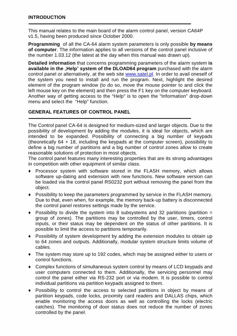
• Access according to timer – the partition controlled by the user, but partition
arming may be carried out only within time periods determined by timers selected. Partition cannot be armed and disarmed in time periods other than time periods determined by timers. For example, if the timer shown in Figure 3 is selected to control access to the “Secretary office” partition, the partition arming and disarming according to the schedule – on Monday between 16:30 and 16:45, on Friday between 18:00 and 18:15 and so on, except time periods given in the timer exception table.
Fig. 3. Timing for partition controlled by timer.
• Timer controlled partition – the partition, where arming is carried out in time periods controlled by timers. When creating the timer controlled partition, you specify the list of timers, which determine the periods when the partition is armed. 32 timers may be selected. The control panel analyses the status of timers selected, and, if any timer status changes to “ON”, the control panel arms the partition. Exit delay time is counted-down before entering the full armed status. The partition is disarmed when all timers selected are “OFF”
Fig. 4. Selection of timers for partition controlling.
The partition can be also controlled by means of a seperate “Partition user timer”, whose mode of operation is programmable through the user function “Change option”. The timer controls the partition independently of the other timers, and in case the “Timer priority” option is on, it prevents the partition from being armed by the other timers or by the user’s code when the timer is inactive (the time interval between the disarming hour and the arming hour). An attempt of arming will result in automatical disarming the zone when the control panel clock counts off a full minute. Provision is made for the partition disarming / arming by the user when the user’s timer is active (the time interval between the disarming hour and the arming hour).
NOTE: When the partition is armed by the timer, the event “Automatic arming” is registered. The event specifies the timer number. Number 0 indicates that the user timer armed the partition.

FUNCTIONAL DESCRIPTION 9
If the object is watched by guard, the round monitoring and signalling of guard absence in specified time is possible – when the guard types his code on a partition or lock keypad; this is registered in the memory of events. Times connected with that are declared for each partition separately; when “0” time is programmed, the monitoring function is switched off. It is possible to differentiate monitoring times depending on whether the partition is armed or not. When partition round requires violation of detectors and the guard has no right to switch detectors off, it is possible to programme the bypass time period, which starts when the guard enters his code to make a round. The guard may use a proximity card or DALLAS chip when carrying out the round. Also, partition bypass may be activated by entering the code like “Temporary partition bypass”. If the system protects cash points by means of zones type “24 h – for cash points”, each partition may contain one cash point only. Access to the cash point is possible after entering the code of type “ Cash point bypass” from LCD keypad (or computer). This bypass starts the “time for approaching” the cash point (“24 h – for cash points” zone is still armed), and, after that time period, bypass time period is counted-down (then “24 h – for cash points” zone is bypassed).

10 System description and installation CA-64 SATEL
Codes and users
Control panel operation (arming and disarming, resetting of alarms and access to functions) is possible after entering the code assigned for the user. The code identifies the user, his authorisation level in the system and access to partitions and selected parts of the object (the access is controlled with locks controlled by the control panel CA-64). CA-64 control panel uses three code types: 1) Service codes – this code identifies the user with special rights: he controls all
partitions, he can open all doors controlled by the control panel, he has access to all functions (except “Service access” function, which appears in function menu for the administrator only). The code is stored in the EEPROM memory, therefore, it is not lost after removing the 3.6V battery jumper (memory of settings and memory od events backup) when the control panel is not powered.
2) Administrator (supervisor) code– this code identifies the user with authorisation rights given by the service, except rights of access to the “Service access” function, which always is accessible for the administrator. If a number of subsystems is defined in the system, each subsystems has its own administrator code. Administrator codes are stored in the EEPROM memory.
3) User code – the rest of codes entered to the system by service or administrators, stored in RAM memory with battery backup. These are the codes for everyday operation of the system. 192 user codes may be entered in CA-64 control panel.
NOTE: Taking into account safety of the system (unauthorised persons may peep at the code), it is recommended to assign a code from the group of user codes, with proper limitation of rights, to the administrator for his everyday usage.
The user is entered to the system by calling the function “New User”. The following is determined there:
• Code – the code assigned to a new user (if the user is provided with rights to change his code, he should change his code!).
• Telephone code – the code for user identification when he use the function answering the phone call. If the user is not assigned with this code, he be not able to check statuses of his partitions and control the relays by phone (relays – outputs controlled by phone).
• Partitions – partitions which may be accessed by the user (e.i. which he can arm and disarm and reset alarms). The list of partitions shown in this function is limited to the partitions accessible for the user, who enters a new user. When the service enters a user, the system asks about the user subsystem before selecting the partitions.
• Type – definition of additional properties of the code: 1. Normal – basic code type assigned to the user. 2. Single use – code for single use. 3. Time renewable – code, for which the validity time period is given when
entering a new user. Before the validity period elapses, the control panel reminds the user with such a code, that he has to change this code. After this change, the validity period is counted-down from the beginning.
4. Time not renewable– code, for which the validity time period is limited to a number of days specified when entering a new user. Validity period may be

FUNCTIONAL DESCRIPTION 11
changed for this code type by the user, who entered a new user, or by the administrator or service.
5. Duress – code similar to normal user type, but the use of this code generates additional event, which is sent to monitoring station (“Alarm – forced activity”) and activates an alarm of the “alarm DURESS” type.
6. Monostable outputs – code that switches on outputs of “MONO-switch” type assigned to partitions covered by this code.
7. Bistable outputs – code, which changes the status of outputs of the “BI-switch” type assigned to partitions covered by the code.
8. Partition temporary blocking – code, which activates the temporary partition bypass (during the bypass period, although the partition is armed; the violation of partition zones does not trigger an alarm). The bypass time period is determined individually for each partition.
9. Access to cash point – code, which activates the function of access to a cash point.
10. Guard – global code, which may be used for making rounds by guards in all system partitions. Typing of this code (typing: CODE#) on a partition keypad at the partition, to which a specific user doesn’t have access, generates an event “Guard Round” and activates partition bypass. Typing of this code on the lock keypad or getting access by means of a proximity card or DALLAS chip generates the event of the “User Access” type. The settings of access control module options decide whether the events mentioned above are generated or not. When the guard is provided with access to partitions, the partitions may be controlled in a way similar to the control of the “normal” type code. Using by a guard the code, card or DALLAS chip at the equipment assigned to the partition, where the guard round is programmed, starts time counting-down to the next guard round from the beginning.
• Rights – this indicates which functions are accessible for the user. The user addition function suggests the list of rights limited to the rights of the user, who enters a new user (the user, who enters a new one, cannot provide a new user with access to functions, which he cannot call by himself).
• Name – user name, which appears in selection lists, printouts and when viewing the events memory.
• Existence time – parameter, which is programmed for codes with defined validity period only (see Type = 3 and 4).
After the new user is added, the control panel indicates the number of the user in the system, which is sent to the station in events that contain this number together with the code (when monitoring in Ademco Contact ID format is activated).
Monitoring
The CA-64 control panel phone communication unit may monitor events to two stations. Two telephone numbers are assigned for each station (basic and backup ones), and the possibility of determining different transmission formats is provided. When monitoring a single station, the control panel carries out dialling trials to the basic and backup numbers alternately.

12 System description and installation CA-64 SATEL
When the “Monitor for Station 1 or 2” mode is on, the control panel dials in the following sequence: station 1 basic number, station 1 backup number, station 2 basic number, station 2 backup number, station 1 basic number and so on, until the number of trials determined for each station is reached. After the programmed number of trials is completed, the control panel hangs monitoring either until a next event occurs or for the time defined by the service (the control panel starts the next series of trials to transmit the message after that time elapses).
NOTE: 8 is the typical value for parameter “Repetitions”, and typical value for the parameter “Hanging period” = 30 (occurrence of a new event causes all not transmitted events to be sent now).
Fig. 5. Window for format selection and definition of identifiers.
Events in the system are divided into eight classes: 1) alarms from zones and tampers, 2) alarms occurring in partitions (e.g. PANIC, fire alarm from the LCD keypad), 3) arming and disarming, 4) zone bypass, 5) access control, 6) system failures, 7) functions used, 8) other events in the system (e.g. start of the service mode). Event of 5 and 7 classes are not monitored. Other events are transmitted depending on transmission format selected.

FUNCTIONAL DESCRIPTION 13
Fig. 6. Widow for assigning partition events to identifiers.
• For pulse formats and Ademco Express it is necessary to program event codes.
Only those events are transmitted, which are assigned to a valid identifier (e.i. those, which have at least three characters different from “0”) and which code is different from “00”.
• When format “E: Ademco Contact ID (selected codes)” is selected, those events are transmitted, which have been transmitted in pulse formats and it has no meaning which code is programmed, since the control panel transmits codes according to the format specification.
• When format “F: Ademco Contact ID (all codes)” is selected, there is no need to program any event codes and assign events to identifiers. The control panel transmits codes according to the format specification and the defined division into subsystems.
NOTES: • When format „E: Ademco Contact ID (selected codes)” is selected, the control
panel may transmit such events only, for which there is a possibility to be transmitted in pulse formats. Not all possible events have their equivalents in pulse formats. Programming of codes for all possible events in the system would require to reserve tens identifiers for the control panel.
• For E and F (Ademco Contact ID ...) formats, each subsystem has its own identifier. Therefore, the identifiers of non-existing subsystems have not to be programmed. In the system event identifier field (events of class 6 and 8), repeat

14 System description and installation CA-64 SATEL
the identifier of the subsystem, which “is responsible” for the system (for example, subsystem, where the control panel is installed).
• For E format, assignation of partition, zones, keypads and expanders to identifiers does not need to reflect the division of the system into subsystems. But it is essential to program the value different than “0”. The control panel transmits all events in the subsystem with a single identifier according to division of system components between subsystems.
• For the operation mode “Station 1 or Station 2” (and “Station N only”, with dialling both numbers), it is not possible to select format F for only one number and another format for the remaining numbers, because it may occur that the event transmitted in format F cannot be converted into type 4/2 code.
For pulse formats, individual events are assigned to identifiers. This allows optimum utilisation of the available space for codes (8 x 225 codes = 1800 codes) – events from smaller subsystems may be grouped with a single identifier, and several identifiers may be assigned for larger subsystems. Event codes are programmed after the division is made. Program DLOAD64 (and corresponding service functions) shows all events assigned to the identifier to facilitate correct programming of codes (the fields for only those codes, which will be transmitted with the identifier, appear in the event code window – see Figure 7).
Fig. 7. Programming of monitoring codes for pulse formats.
System events and failures are transmitted with their own identifier. Figure 8 shows the events assigned to this identifier.

FUNCTIONAL DESCRIPTION 15
NOTES: • Service functions, which reset the system to the factory settings, cause the event
“Reset to factory defaults”. The number transmitted in the Ademco Contact ID format inform, which settings are reset (0 – control panel settings reset, 1 – reset of codes). Clearing of the event memory is transmitted with a separate code.
• Event “RAM memory error” informs on error(s) in the settings memory that is backed-up with a 3.6V battery. If the settings are stored in the FLASH memory, detection of this error forces “Panel restart” that will be followed by “Data restore”.
• “Control Panel Restart” appears at each power supply connection.
• Control panel CA-64 allows a monitoring test of two types: transmitting the event “Periodical reporting Test” either every day at a specified time or after a programmed time period from the last communication with the station (it is possible to activate the both types simultaneously). Additional transmission may be initiated with the user function, when the code “Manual reporting test” is programmed.
• Checking communication with the station is facilitated with the function “Test of Station XX” (in the user function menu “Tests”), accessible after station phone numbers, system event identifier and “Reporting Test” code have been programmed. Calling of this function initiates monitoring, where the control panel informs on current transmission phase and test result at the keypad.
Fig. 8. System event codes. NOTE: Event codes shown in Figures 7 and 8 are examplary only and are shown
here as an example of programming. The codes are programmed according to recommendations of the monitoring station.

16 System description and installation CA-64 SATEL
Messaging
Function of messaging, featured by the control panel CA-64, allows informing on alarms with messages sent from voice synthesisers or transmitted to pagers. Messaging is made independently from monitoring, where monitoring has priority. If during messaging events occur on which the control panel must inform the monitoring station, monitoring will be included between pieces of information. Messages may be transmitted to 16 phone numbers. It is possible to send 16 different vocal messages and 64 different pager messages. When reporting with the use of vocal messages, it is possible to confirm the message receipt. A special code, connected with a telephone number, is used for that purpose (it is possible to establish any code – four digits transmitted with DTMF mean the receipt of a message). The control panel confirms code receipt with a special signal. If there is a number of messages to transmit to a single phone number, all these messages are transmitted during a single phone-call. In this event, the signal confirming that the message is received is different (which informs that further messages should be awaited).
Fig. 9. Programming of a phone number for messaging.
Fig. 10. Difining the way of informing on alarms for zones.

FUNCTIONAL DESCRIPTION 17
Due to the possibility of detailed definition how to inform on each alarm, the control panel CA-64 allows to organise an additional monitoring, based on the informing function, that operates simultanously with the basic monitoring. The way of defining the rules of informing on alarms for zones is shown in Figure 10. The rules of informing on other alarms are programmed in the same way. Messaging may also include information on power supply failure.
NOTE: When informing on alarm, the control panel performs a cycle of phone calls dialling all specific phone numbers in sequence. The numbers, which confirmed alarm message receipt with a code, are not dialled any more. Other phone numbers are informed in the next cycle according to the defined number of repetitions.
Answering a phone call
The control panel CA-64 is provided with the function of answering external phone calls, called in the same way as when starting programming by telephone (double calling after a defined number of “rings” or calling after a number of rings received and receipt blockade of the next phone call). Only the users, who are assigned with a special “telephone” code may have access to this function. When the control panel answers incoming phone call, it generates the confirmation signal (three short beeps) and waits for the user code. Using the telephone set keypad (of the telephone with which he called the control panel), the user types the code in the DTMF tone system. The correct code receipt is confirmed with four short beeps and one long beep, and activates function of informing on partition statuses. By typing two-digit partition number, the user obtains an information whether the partition is armed and whether an alarm occurred in that partition (three short beeps – the partition is disarmed, four short beeps and one long beep - the partition is armed). Questions about the statues in partitions, to which the user has no access, are rejected (two long beeps).
Fig. 11. Determination, which phone relays may be controlled by the user.
The function of phone call answering allows also the control – by giving the command 2#, the user triggers the control panel into the control function. Typing the two-digit

18 System description and installation CA-64 SATEL
phone relay number causes switching this relay on or off. The control panel informs on the new relay status with a proper signal (three short beeps – relay is switched off, four short beeps and one long beep – relay is switched on). Status change commands for relays, which the specific user is not allowed to control, are rejected by the control panel. Type command 1# to switch over to the function of informing on partition statuses. Type command 0# to exit the phone call answering function. The control panel abandons the phone call answering function, when no DTMF character is received during 15 seconds.
NOTES: • Not all cellular telephones allow DTMF control.
• When the phone call answering function is activated to inform on partition statuses, a single short beep is heard periodically. When an alarm has occured in a given partition, an additional, of much lower frequency short beep is generated before the short beep mentioned above.
• After triggering to the control function, a periodical signal appears – two short beeps.
Remote programming
Two programmes, DLOAD64 for use by the service (installer) and GUARD64 for use by the user, allow control panel CA-64 programming and control. Both programmes run in Windows95/98 environment. Control panel CA-64 is provided with several mechanisms of programming by means of computer:
• Programming via main card RS-232 port and DLOAD64 program, which allows quick data transmission and convenient viewing of statuses of zones, partitions, outputs, module tampers, doors controlled by the control panel and of other system elements.
• Programming via the modem built-in into the control panel and DLOAD64 program, which communicates with the control panel via modem and telephone line. This way of programming makes all downloading functions accessible, but, due to baud rate limitation to 300 bauds, functions run longer time. The supervision by DLOAD64 of changes in control panel settings allows transmission of only these blocks of data, where the changes have been made. The time of programming via the telephone is shortened due to that.
• Programming via the external modem connected to the main board RS-232 port and DLOAD64 program, which communicates with the control panel via modem and telephone line. If both modems are configured properly, this programming mode allows the same possibilities as for direct connection via RS-232.
• Programming via external LCD keypad RS-232 port and GUARD64 program. This programming mode operated independently from other, makes possible users management, viewing the object status and viewing the event memory contents. It is possible to start this operation mode at all LCD keypads at the same time.
Control panel STARTER
The control panel software is stored in the FLASH memory to allow programming on site (without removing the memory chip from the control panel main board). The

FUNCTIONAL DESCRIPTION 19
software consists of two parts: The STARTER program designed for programming the FLASH memory, and the control panel program. When the program STARTER runs, the control panel normal functions are deactivated (status of electronic circuit protectors only is monitored). When the program STARTER runs, the LED at the telephone line relay quickly blinks and a proper message is displayed at all LCD keypads. Program STARTER does not operate partition keypads, and their LEDs light in sequence: from most top one to the lowest one. The STARTER program may be triggered to the programming mode in two ways: 1) By calling it from the service mode function menu. 2) By switching on the control panel power supply with RESET pins shortened.
Remove jumper immediately after the control panel has switched on power supply at outputs supplying keypads and expanders (when the jumper is not removed before calling the control panel program by STARTER, downloading via RS-232 will be started or the control panel will trigger to the service mode).
NOTES: • When program STARTER is in the programming mode, the message “STARTER
2.2 is running...” is displayed at LCD keypads. This informs on readiness to operate with the FLASH64 program (it should be started in the computer connected to the control panel main board via RS-232). If the STARTER program receives no command from the computer within 2 minutes, the control panel program will be restarted.
• When the control panel is connected to the computer, the STARTER program may be stopped by calling the command “ Restart CA-64” in the FLASH64 program ( Ctrl-F2, then indicate the port, to which the control panel is connected)
CONTROL PANEL INSTALLATION
Control panel CA-64 should be installed in closed rooms with normal air humidity. Permanent (not disconnectable) power supply 220 VAC with protective ground should be available in this room. The telephone line must be made from four-wire cable to make possible connection of the control panel to other equipment (telephone, fax etc.).
NOTES • Install main board fixing pins prior to the control panel housing installation.
• When installing the housing, pay attention not to damage cables to be put through openings in control panel housing rear wall.
• The control panel main board and the expander modules need not be grounded.
• Switch off mains power supply and battery power supply when connecting LCD keypads and other components powered from control panel outputs.
CAUTION!
Since the control panel is powered from 200VAC mains, carelessness when wiring or incorrect wiring may lead to electric shock and danger to life! Therefore, be very careful when wiring the control panel. The power supply cable cannot be live when installing and connecting it to the control panel!

Fig. 12. The arrangement of units on the CA-64 control panel.
BO
AR
D T
ER
MIN
ALS
:
AC
-
modu
le su
pply
zone
s(20
...24
V AC
) Z
1 to
Z16
- zo
nes l
ines
OU
T1
to O
UT
16
- pr
ogra
mm
able
outp
uts
+KP
D, D
TM
, CK
M
- ke
ypad
bus
+E
X1,
DT
1, C
K1
- fir
st bu
s of e
xpan
ders
+E
X2,
DT
2, C
K2
- se
cond
bus
of e
xpan
ders
C
OM
- g r
ound
TIP
, RIN
G
- o
utsid
e te
lepho
ne lin
e T
-1, R
-1
- i
nside
telep
hone
line
(telep
hone
set c
onne
ction
) +1
2V
-
supp
ly ou
tput
S
YN
T1,
SY
NT
2 -
conn
ecto
rs fo
r voic
e sy
nthe
sizer
s R
S-2
32
- c
onne
ctor f
or se
rvice
com
pute
r
BATT
ERY
CHAR
GE
5
00m
A
1
000m
A
RESE
T
R-1 T-1 RING TIP
5W 0.1ΩJ T3.15A
DIAL
ER
SYNT
1 SY
NT2
CHAR
GE
+12V
OU
T5
OUT6
OU
T7
OUT8
AC
AC
COM
OUT
1 CO
M O
UT2
COM
OUT
3COM
OUT
4COM
+KPD
DTM
CKM
COM
+EX
1 D
T1 C
K1 C
OM +
EX2
DT2
CK2
Z
1 C
OM
Z2
Z
3
COM
Z4
Z
5 C
OM
Z6
Z7
CO
M
Z8
Z
9 C
OM
Z10
Z11
COM
Z1
2 Z
13 C
OM
Z14
Z15
C76
+12V
OU
T9
OUT1
0 OU
T11
OUT1
2 OU
T13
OUT1
4 OU
T15
OUT1
6 CO
M
MEM
ORY
SERI
AL
PORT
RS-
232
RED BLACK
BATTERY

CONTROL PANEL INSTALLATION 21
Connection of LCD keypads
Up to eight independent LCD keypads, designed for control and programming the alarm system, may be connected to the control panel CA-64. When some keypads are being connected to the control panel, connect them in parallel. Since keypad bus data are addressed, all keypads operate independent of each other. LCD keypads are to be connected to COM, +KPD, DTM and CKM terminals. Output +KPD makes possible to power all eight keypads (this output is provided with electronic protective circuit breaker with a 3A limiter). Each keypad must be connected with its separate cable (it is recommended to use a typical, non-screened cable). Maximum distance between keypad and control panel is up to300 m. The lowest possible resistance of cables is important for correct operation of keypads. Depending on the distance between a keypad and the control panel the following number of cable wires must be provided for individual connections when using a typical cable DY 8x0,5 in.
Distance Description Number of cable wires
up to 100 m Power supply +KPD and COM ground CKM and DTM signals
2 x 1 2 x 1
up to 200 m Power supply +KPD and COM ground CKM and DTM signals
2 x 2 2 x 1
up to 300 m Power supply +KPD and COM ground CKM and DTM signals
2 x 4 2 x 2
NOTES: • CKM, DTM and COM wires must be in the same cable!
• Power supply measured at the LCD keypad terminal, when the backlight is on, cannot be less than 11V.
• The presence of power supply voltage at the +KPD terminalr is signalled by the fifth LED in the electronic circuit breakers block.
• Keypads, which are installed far from the control panel, may be powered locally from an independent power source. These keypads are connected to the system with the use of CKM, DTM and COM signals.

22 System description and installation CA-64 SATEL
The control panel identifies the keypads tracking addresses set by means of jumpers at the keypad board. The addresses must be unique! A keypad address also determines the numbers of keypad watching zones Z1 and Z2. These zones are operated by the control panel in the same way as main board zones.
Address Positions of jumpers ABC Numbers of Z1 and Z2 zones
0 49 and 50
1 51 and 52
2 53 and 54
3 55 and 56
4 57 and 58
5 59 and 60
6 61 and 62
7 63 and 64 address = 6 RS-232 LCD Keypad Fig. 13. Positions of jumpers for determining the address and description of keypad
terminal.
NOTE: If zone expanders are included in the system (more than 4 expanders), and their zone numbers are the same as the numbers of keypad zones, when programming the control panel, specify whether the detector is connected to the keypad zone or to the expander zone
Correctly connected keypad reports its restart, and a date and clock appears on its display; when wiring is incorrect, the message “No communication with control panel” is displayed. System control is possible after the service function Identification of keypads is performed. This function checks to which addresses keypads are connected and registers them in the system. Disconnection of a keypad registered in the system causes tampering alarm. Any commands from a keypad not registered by the control panel are rejected (the message “Keypad is not serviced” appears at the keypad display). The LCD keypad port RS-232 is designed for connection of a user’s computer. It operates with the Guard64 program that allows system control by means of a computer (virtual keypad, users authorisation edition) and supervision (plan of the object showing statuses of partitions and detectors, viewing events memory). Connection to the computer is permanent, made using an ordinary, non-screened cable. For a typical DY8x0,5 cable, the distance between the computer and the
A C B
+K
PC
KD
TM
Z
1 C
OZ
2

CONTROL PANEL INSTALLATION 23
keypad cannot exceed 100 metres. Keypad connector signals are shown in Figure 14.
DSR keyp.
RXD keyp.
DTR comp.
TXD comp.RXD comp.TXDkeyp.
COM GND
KEYPAD
COMPUTERSERIAL PORTRS-232
2
3
7
20
2345
Fig. 14. Connection of the computer to the LCD keypad RS-232 port.
NOTE: Switch on the “RS communication” option in parameters of keypads, to which user’s personal computer is to be connected. Data exchange with the computer starts automatically, when the Guard64 program is started.
Each LCD keypad contains individual set of parameters, which determine its way of operation in the system. These are:
• “Operated partitions...” – partitions, which can be armed/disarmed or alarm may be cancelled from the keypad. Control will be possible for those users, who have access to partitions specified here. When any partitions specified here is armed, the keypad LED ARMED blinks. When all partitions specified here are armed, this LED lights steadily.
• “Signals the alarms...” – list of partitions, for which a burglary alarm will be shown in the keypad. Alarm will be indicated by LED ALARM and message at the display will appear (when option “Alarm messages” – “partition” is on). Additional option “Alarm signalling” determines whether an alarm is signalled audibly.
• “Signals GONG...” – list of zones, violation of which causes audible keypad alarm.
• „Quick Arm” – partitions, arming of which will be activated after typing 0# on the keypad.
• “Tampering causes alarm...” – partition, in which an alarm occurs after tampering of the keypad or when the keypad is disconnected from the system.
• “Alarm messages” – when an alarm occurs for the zone belonging to the partition operated by the keypad, or other alarm in partition operated by the keypad takes place, alarm message appears at the display.

24 System description and installation CA-64 SATEL
Fig.15. Parameter defining LCD keypad operation.
• “Alarms” – keeping pressed, 0 or # may trigger alarm ( - fire alarm, 0 – call for medical assistance, # - PANIC alarm).
• “Signalling entry/exit delay...” – keypad may signal audibly entry and exit delays in partitions operated from the keypad.
• „Auto-backlight” – violation of a zone indicated or counting-down the entry delay for a specified zone may switch on backlighting of keypad keys and display.
• “Characters” – it is possible to define, which characters are used for signalling statuses of zones in function “Zone viewing” (this function shows status of 32 zones at the keypad display, similar to LED keypads).
Connection of expansion modules
Control panel CA-64 is provided with two buses designed for connecting the expansion modules (expanders). Both buses have the same priority and are serviced in parallel (in has no meaning, which modules are connected to each bus). All modules are connected in parallel, and up to 32 modules may be connected to each bus. Data transmission is carried out via DT1, CK1 and COM for the first bus, and via DT2, CK2 and COM for the second bus. Additionally, power supply for modules is provided at +EX1 and +EX2 terminals. Both power supply outputs are connected to

CONTROL PANEL INSTALLATION 25
common electronic circuit breaker (limitation 3A), the presence of power supply voltage is signalled by the sixth LED in the electronic circuit breaker block. Modules may be connected with the use of a typical, non-screened cable used in alarm systems (for example, DY8x0,5). Signals DTn, CKn and COM should be contained in one cable (cannot be led through separate cables). For small distances (up to 100 metres), when only modules are connected to the power supply cable, it is permissible to connect some modules one after one (see Figure 16). Additional equipment connected to the power supply source must be supplied through separate cables (detectors connected to modules A and B).
Z 8
COM
Z 7
Z 6
COM
Z 5
CONTROL
+12V
+12V
+12VDATA CLK COM
COM
TMP
Z 8
COM
Z 7
Z 6
COM
Z 5
+12V +12VDATA CLK COM TMP
Z 8
COM
Z 7
Z 6
COM
Z 5
+12V +12VDATA CLK COM TMP
+Exn
DT n
CK n
COM
UP TO 100 mUP TO 100 mUP TO 100 m
+12 V
NO
C
TAMP
TAMP
GND
DETECTOR
+12 V
NO
C
TAMP
TAMP
GND
DETECTOR
EKSPANDER A EKSPANDER B EKSPANDER C
PANEL
Fig. 16. Correct connection of modules for small distances between the control panel
and modules, and way of detector connection.
NOTE: Connection of fourth module after module C is not recommended when a typical cable DY8x0,5 is used. The module connected in this way may be not “seen” by the control panel. Resistance of cables at DTn and COM causes that logic level “0” at the control panel input may be higher than the maximum allowable level.
For large distances between the control panel and modules (up to 1000 metres), modules should not be powered from the control panel, and DTn, CKn and COM signals should use two-wire cable. Additionally, signals DTn, CKn and COM must be in one cable. It is possible to connect several modules in parallel and connect them to a single, common cable, through which the DTn, CKn and COM signals will be connected (see Figure 17). For example, when the distance from the control panel to the cabling node is 800 metres and the distance from the cabling node to the module is less than 100 metres, it is possible to connect up to 16 modules.

26 System description and installation CA-64 SATEL
Each module connected to the bus should have its own, unique address. It has no meaning, which addresses are set for individual modules (the control panel receives an information on module type and automatically sets optimum sequence of calling the modules for data). Address is set by means of switches marked ADDRESS ABCDE.
EKSPANDER n+12V
+12V
DATA
CLK
COM
TMP
Z 8 COM Z 7 Z 6 COM Z 5
EKSPANDER n+12V
+12V
DATA
CLK
COM
TMP
EKSPANDER n+12V
+12V
DATA
CLK
COM
TMP
POWER PACK OR EXPANDER WITH POWER PACK +12V
+12V
COM
COM
COM
CK n
DT n
UP TO 1000 m
CONTROL
Z 8 COM Z 7 Z 6 COM Z 5
Z 8 COM Z 7 Z 6 COM Z 5
PANEL
Fig. 17. Connection of module group located far from the control panel.
The control panel services the modules registered in the system by means of the service mode function Identification of expanders. This function determines expander addresses and types. Additionally, it defines a special random generated marker, with which the module confirms its presence in the system. This marker is stored in module non-volatile EEPROM memory, and it may be changed in a next identification process only. Therefore, each module replacement, address change and change of module type under given address require running of the identification function again.
NOTES • The control panel does not service the modules when the identification function is
not completed with message “X modules found”.

CONTROL PANEL INSTALLATION 27
• Erratic module wiring may cause that the modules cannot be identified correctly,
what is signalled with message “The same address for two modules”.
• Too high resistance of cables connecting module to the control panel (large distance, too small number of wires for a single signal) may cause that the identification function does not see the module.
• When modules are being serviced by the control panel, LEDs at zone, output, synthesizer modules (and other, which are provided with operation signalling for service only) change their status.
Connection of detectors
CA-64 may operate with any detectors. Each control panel zone and zones of LCD keypads and zone modules may operate in the following configurations:
• NC (normally closed),
• NO (normally open),
• EOL (single-parameter),
• 2EOL/NO (double-parameter, NO type detector),
• 2EOL/NC (double-parameter, NC type detector).
When a zone operates in a configuration with a single parameter (EOL), use 2,2 kΩ resistor to close the detector circuit. For double-parameter zones (2EOL), detector circuit is closed with two resistors 1,1 kΩ. 2EOL type zones allow the control panel to control detector status and detector tamper switch simultaneously. Any output with electronic protection (from OUT1 to OUT4) may be used to power detectors. This output should be programmed as “POWER SUPPLY OUTPUT”. For larger systems with buffer power packs with high capacity batteries, detectors are powered from external power sources. Figure 18 shows how to connect detectors to zones working in a double-parameter configuration. Separation of detector power supply ground and ground of the signal informing on status of detector connected to the control panel monitoring zone eliminates the influence of the resistance of wires on the detector status detection. Assuming that only one detector is connected to the cable and the cable length is not big, the installation may be simplified by leading a common single wire for power supply ground (GND) and signal ground (COM).
GND TAMP C NO +12
to detector power supply circuit
COM(zone n)Zn
2 X 1,1kΩ
COM(power (zone)supply)
Fig. 18. Connection of a 2EOL detector to the control panel.

28 System description and installation CA-64 SATEL
NO and NC detectors in a double-parameter configuration are connected in an identical way, but it is important to inform the control panel which detector is connected to the zone (2EOL/NO or 2EOL/NC).
+12 V
NO
C
TAMP
TAMP
GND
Z 8
COM
Z 7
Z 6
COM
Z 5EKSPANDER
CONTROL
+12V DATACLKCOM
COM
CK n
DT n
+12 V
TMP
CAUTION!
DETECTOR POWER SUPPLY GROUND AND SIGNAL GROUNDMUST USE SEPARATE WIRES
EXPANDER CASING TAMPERING
DETECTOR+12V
PANEL
Fig. 19. Connection of 2EOL detector to the expander for small distance between the control panel and the expander (detector is located far from the expander).
NOTE: Recommended power supply circuit for detectors connected to expanders is shown in Figure 16 (point “Connection of expansion modules”).
Connection of signallers
Control panel CA-64 is provided with 16 outputs, application of which may be programmed. In order to connect a signaller to the control panel, it is necessary to program this output as an alarm output. Four outputs are for high amperes with electronic circuit breaker set to 3A. The structure of these outputs and the the way of connection to them signalling devices without their own power supply (or without other loads) are shown in Figure 20.
COM OUT1 COM OUT2 COM OUT3 COM OUT4
LOAD
LED FOR INDICATION OF OUTPUT STATUS
LIMITERS 3A 3A 3A 3A
+13,6V
_
+
_
+
_
+
_
+
Fig. 20. Connection of a load (e.g. signaller) to outputs OUT1..OUT4.

CONTROL PANEL INSTALLATION 29
NOTES: • Outputs OUT1..OUT4 are provided with a load presence detection unit, which is
active when output is not active. If a load is connected correctly and the control panel indicates failure “No load present...”, connect a 2,2 kΩ resistor in parallel to the load.
• When the signalling device connected to the output in parallel to the resistor 2,2 kΩ generates undesirable sounds, reduce value of resistance.
• Add 2,2 kΩ resistors to OUT1..OUT4 if these outputs are not used. Remaining 12 control panel outputs are designed for control (for example, to control signaller with their own power supply). Loads connected to these outputs (e.g. relays) cannot demand the current exceeding 50 mA. Structure of OUT5..OUT16 outputs and their use are shown in Figure 21.
OUT 5
OUT 16
+13,6 VOUT 5OUT 6OUT 7OUT 8
OUT 11OUT 10OUT 9
OUT 12OUT 13OUT 14OUT 15OUT 16
+13,6 V
COM
LOAD50 mA
POTENTIAL-FREE
+
+
+13,6V
ROUT n
+ Ucc
+12V
POUT n
RELAY OUTPUT
OUTPUT
Fig. 21. Connection of loads to outputs OUT5..OUT16 and signals from these outputs
(e.g. to the radio transmitter).
NOTE: Power supply at connectors J22 and J23 is connected to power supply outputs for expanders at the control panel board. Therefore, it is not recommended to connect to it equipment exposed to tampering (e.g. signallers with their own power supply).
Connection of telephone line
If the system uses the control panel telephone communicator (for monitoring, messaging or remote programming), it is necessary to bring the telephone line to the control panel. Telephone line is plugged to the terminal located in upper right corner of printed board. In order to ensure correct messaging, the control panel must be connected directly to the telephone line (terminals marked TIP, RING), and all other equipment (telephone set, fax) – downstream the control panel (terminals marked T-1, R-1). Such connection allows the control panel to fully take over the telephone line for the time of phoning, which prevents the possibility of the messaging function to be blocked by picking up the handset. Additionally, the telephone sets connected behind the control panel do not signal phone calls made by the control panel.

30 System description and installation CA-64 SATEL
Connection of voice synthesizers
In the event the function of messaging on alarm by phone with a vocal message is used, it is necessary to connect at least one voice synthesizer to the control panel.
Control panel CA-64 is provided with two sockets for connecting voice synthesizers SM-2. Both sockets are located at the right side of printed board, between telephone line connector and J22 and J23 connector sockets. The socket marked SYNT1 is applied for connection of the Synthesizer 1 message, and SYNT2 – for the Synthesizer 2 message. The messages may be listened to and telephone line listening-in is possible at both SM-2 synthesizers.
Fig. 22. Arrangement of signals at voice synthesizer SM-2 connectors.
When a larger number of messages is needed, it is necessary to use the expander module type CA-64 SM. These synthesizers are controlled via the extension bus, and audio signals are connected to SYNT1 or SYNT2 terminals.
Connection of printer
Control panel RS-232 port allows connection of a printer provided with a serial port. The control panel may print events in a “compressed” format (single event is printed in a single line containing up to 80 characters) or “extended” format, with names of zones, partitions, users and modules (then, the event is printed in two lines, when the printer with up to 80 characters per line is used; the descriptions of a single event are printed in one line with printers printing 132 characters per line).
DSR cont. p. DTR prin.
RXD prin.TXD cont. p. COM COM
12
3
45
6
SERIAL PORTRS-232
3
7
20
2
45
(view of connector at the control panel board)
Fig. 23. Connection of a printer to the control panel serial port.
ground
low frequency signaltriggering
power supply, +
control panelprinted board
telephone line listening in
CONTROL PANEL INSTALLATION 31
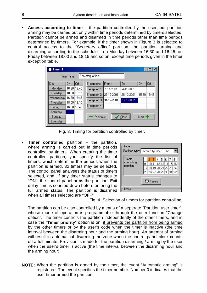
Connection of service computer
In case of control panel CA-64 programming with the use of a computer and the “Downloading” function via control panel RS-232 port, the computer should be connected according to Figure 24. It is possible to connect the computer by means of the cable used for programming of CA-10 control panels. But there is here a certain inconvenience: if the control panel uses the telephone line when exchanging data with the computer (monitoring, messaging), the message “Caution! Control panel does not answer” may appear in DLOAD64 program. This effect will not occur when the connections are made in accordance with Figure 24, because the control panel informs the computer on a temporary pause in servicing the RS-232 port via an additional wire.
DSR cont.p.RTS cont.p.RXD cont.p.
DTR comp.CTS comp.TXD comp.RXD comp.TXD cont.p.
COM GND
SERIAL PORTRS 232
2345
8
23
5
7
20
(view of connector at the control panel board)
Fig. 24. Connection of a computer to the control panel serial port.
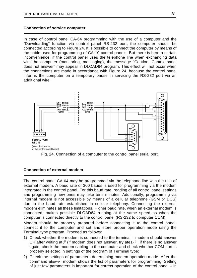
Connection of external modem
The control panel CA-64 may be programmed via the telephone line with the use of external modem. A baud rate of 300 bauds is used for programming via the modem integrated in the control panel. For this baud rate, reading of all control panel settings and programming new ones may teke tens minutes. Additionally, programming via internal modem is not accessible by means of a cellular telephone (GSM or DCS) due to the baud rate established in cellular telephony. Connecting the external modem eliminates all these limitations. Higher baud rate, when an external modem is connected, makes possible DLOAD64 running at the same speed as when the computer is connected directly to the control panel (RS-232 to computer COM). Modem should be properly prepared before connecting it to the control panel: connect it to the computer and set and store proper operation mode using the Terminal type program. Proceed as follows: 1) Check whether the modem is connected to the terminal – modem should answer
OK after writing at (if modem does not answer, try ate1 ; if there is no answer again, check the modem cabling to the computer and check whether COM port is properly selected in settings of the program of Terminal type).
2) Check the settings of parameters determining modem operation mode. After the command at&v , modem shows the list of parameters for programming. Setting of just few parameters is important for correct operation of the control panel – in

32 System description and installation CA-64 SATEL
the parameter block stored as “profile 0” („STORED PROFILE 0” in Figure 26) it must be specified E1 Q0 V1 X4 &D2 &S0 and S00:000.
DSR cont.p.RTS cont.p.RXD cont.p.TXD cont.p. COM
DSR modemRTS modemRXD modemTXD modem
GND
"LINE" CONNECTORIN MODEM
SERIAL PORTRS-232 TELEPHONE
CONNECTORIN CONTROL PANEL
TELEPHONE TELEPHONE LINE
2345
76
234
67 20
R-1
T-1
TIPRING
(view of connector at the control panel board)
Fig. 25. Connection of an external modem to the control panel serial port.
3) If the parameters mentioned above are set correctly, the modem is ready for
operation with the control panel. If any parameter is set to other value, set it properly. Command for parameter setting consists of fixed prefix AT and parameter value required (for example, when profile specifies E0 V0, the command for setting the proper parameter value is ate1v1 , after which the modem answers OK).
Fig. 26. Correct setting of external modem parameters.

CONTROL PANEL INSTALLATION 33
4) after parameter values are set according to the list described in point 2), store the
settings in the “profile 0” (with command at&w0 ). 5) At the end, you may check whether all parameters are stored correctly – after the
command atz , and then at&v , settings in ACTIVE PROFILE should be the same as in STORED PROFILE 0 (note: often STORED PROFILE set contains less number of parameters than ACTIVE PROFILE set, this is normal).
NOTES: • Modem register S0 settings are performed with the command ats0=0 (modem
shows slightly different notation, S00:000, in Figure 26).
• When the control panel restarts the modem, it generates the command ATZ, which sets parameters in accordance with the values stored in the “profile 0”. Therefore, it is not important what are the current values of parameters mentioned in point 2 (“ACTIVE PROFILE”), but it is important that they be correctly set in the “profile 0”.
Connection of power supply
The control panel is permanently connected to a main power source. Therefore, familiarise with the electric system in the object before system wiring. For powering the control panel choose the circuit, which always is live. The power supply circuit should be protected with a proper fuse.
CAUTION!
Disconnect voltage in the power supply circuit to which the control panel is to be connected, before connecting the control panel to this circuit.
Description of electric connections. 1. Connect 220VAC to the terminal block located in the control panel casing under
the transformer shield. Connect “phase” wire to the terminal marked L and “zero” wire to the terminal N, connect ground wire to the terminal marked with the ground symbol (the control panel main board need not be grounded).
2. Connect AC voltage wires from secondary transformer winding to terminals marked with “AC” symbol at the control panel board.
Control panel power supply unit operates with input voltage of 20...24V AC. The control panel is provided with the up-to-date pulse power supply unit, highly efficient and reliable, but, for its correct operation, it is necessary to ensure that input voltage, at maximum transformer load by the control panel, do not fall below 18V (AC).
Control panel power supply starting procedure: 1. Connect the backup power supply wires to proper battery terminals (red to
battery plus, black to battery minus). The control panel will not start after connecting battery alone (without mains power supply), but it will operate in case of 220VAC failure when it was started earlier.
NOTE: When control panel is working and the battery supply voltage drops to approximately 11V, the control panel reports battery failure. After the voltage drops to approximately 9.5V, the control panel disconnects the battery (the system is stopped).

34 System description and installation CA-64 SATEL
2. Connect the 220 VAC mains – the control panel starts to operate. The sequence of power supply switching on specified here (first battery, then 220 VAC mains) ensures correct operation of power supply unit and control panel electronic protections, what allows avoiding failures of alarm system components due to installation errors. Start the modules with their own power supplies in the similar way.
CAUTION! In situation, when total disconnection of control panel power supply (mains and battery) is necessary, switch on the control panel in the way described above (first battery, then mains 220 VAC).
Stabilised voltage of control panel power supply unit is 13.6 - 13.8V, and it is factory set.
After all wiring is made and installation correctness is confirmed, you may start the system. It is recommended to start operation with the control panel without signalling devices. The signalling devices may be connected after completion of parameter programming for the alarm system. For systems with extension modules with their own power supply, it is recommended to start the control panel first, then other system components in sequence.
CAUTION !
Since the control panel is not provided with main switch to disconnect mains, it is important to inform the alarm system owner or user on how to disconnect it from mains (e.g. by showing the fuse protecting the control panel power supply circuit).
Staring the system
Starting of control panel after power supply is switched on is carried out in two stages: 1) First program STARTER starts and checks contents of the control panel program
memory. During this operation, LED adjacent to telephone line transmitter flashes and message STARTER 2.2 of control panel CA-64 is shown on LCD keypad displays. When the contents of FLASH program memory is correct, STARTER starts the program of the control panel.
2) The program the control panel starts with checking the memory of settings (RAM memory with backup battery 3.6V/60mAh). If the differences, comparing to settings programmed by service, are detected, proper settings will be restored from FLASH memory (this test is skipped when control panel settings are not stored in FLASH memory; question about storing the settings appears when exiting service mode). The control panel starts to operate after settings are checked.
NOTES: • If the error in the control panel program is detected, the message “Download
correct program to the control panel” appears on LCD keypad displays and STARTER program waits for new program from the computer. Error in program may occur only when the control panel software up-dating process has been stopped by switching power supply off.
• When the control panel is not powered, removal of jumper MEMORY causes cancelling the contents of memory of settings, user data, event memory and clock. After power supply is restored, the control panel restores memory of

CONTROL PANEL INSTALLATION 35
settings only. User data must be programmed again. Data on administrator and service codes are stored in the separate EEPROM memory and they are not lost after removal of jumper MEMORY.
STARTING THE CONTROL PANEL
Correctly installed control panel should start after mains power supply is switched on, as described in point Starting the system. The control panel with the factory software (after restart of settings) operates all keypads installed just as if they are identified. However, it does not monitor keypads tampering and their zones, and does not allow programming of keypad operation parameters. When connected to the computer, it forces generation of a new data set.
NOTES: • Before commencing control panel programming, it is necessary to perform
identification of keypads and expanders. This will allow access to parameters programmed for the existing hardware.
• If the control panel is to be remotely programmed via the telephone line, it is necessary to program telephone number of the service computer.
• Hardware identification and programming of the service telephone number are made with proper service functions.
Service mode
Control panel programming from LCD keypad is carried out with the use of service functions accessible from service mode menu. This mode is switched on by the service (installer) choosing the entry “Service mode” in user function menu. How to activate the service mode (codes as for restart of settings): 1. Open service access:
a) type the administrator code and press (press 1111 ), b) select the entry “Service access” from the list and enter this function ( key # or
), c) specify service access time (in hours) and confirm it with key #.
2. Type service code and press (press 12345 ), 3. Select the entry “Service mode” and press # or .
NOTES: • Service mode is indicated with LED marked “SERVICE” at LCD keypads. The
control panel remains in service mode until the user exits it with the use of function “End of TS (Service Mode)”.
• Alarms for zones “24h vibrational”, 24h cash point”, “Sound signalled attack” and “Silent attack” only are possible in the service mode.
If the service mode starting according to the description above is impossible – the control panel does not control the keypad because of any reason – it is necessary to carry out special procedure to start the control panel and enter the service mode “with the use of pins”. To ensure that all settings are in accordance with factory settings, perform functions of setting restarts in the service mode.
36 System description and installation CA-64 SATEL
The procedure is as follows:
1. Check keypad connections to the keypad bus (see page 19). 2. Put the jumper at RESET pins at the control panel board. 3. Switch on control panel power supply – the LED located at the telephone line
transmitter starts to blink. First control panel starting must be carried out with mains power supply unit (without battery). The control panel will not start when connected to battery only.
4. Wait until LED goes off, then remove the jumper from pins – the control panel should enter the service mode menu automatically – the message “→End of TS” appears on the display of keypad with lowest address number, and LED marked SERVICE starts to blink. If the message “Cancel control panel data” 1=Yes” appears on the main display, this means that the access to the service mode “with the use of pins” has been locked in the control panel program (→Service Mode, →Service Mode Configuration, → Service Mode Interlock). Then you can enter the Service Mode by pressing the key marked with digit 1, but, at the same time, all settings previously programmed in control panel will be cleared (just like after performing functions mentioned in point 5). After performing this operation, you may move to point 6.
5. Perform restart functions (→restarts, →Restart of settings; →Restart of codes; →Restart of events).
6. Perform identification functions for modules connected (→Structure, →Hardware, →Identify keypads; →Identify expanders). Note: The addresses in keypads and expanders cannot be changed after
identification has been performed. 7. Complete the service mode with function “End of TS”, storing data in FLASH
memory. When the prompt “Store data in FLASH memory” 1=Yes” appears on the keypad display, press key with digit 1 – new settings will be stored and the control panel will enter the basic operation mode (waiting for code).
8. Call service mode again according to the description on page 33 of installer instructions.
If the control panel entered service mode again, it operated correctly and you can commence further system installation (connection of expanders, detectors, signallers, keypads, etc.), start communication with the computer and program all parameters required.
NOTES: • If the control panel is connected to the computer with DLOAD64 program started,
function of downloading via RS0232 will be started instead of the service mode.
• Entering the service mode “with the use of pins” may be locked with function “TS interlock” (function in “TS configuration” position). Entering the service mode “with the use of pins” may be restored after approval of factory setting restoration.
When exiting the service mode, the control panel CA-64 checks whether parameter values programmed by the service have changed. The message “Wait...” appears on LCD control panel display. If there are no changes in settings, service mode is exited. If there are changes in settings, the control panel asks whether to store settings in FLASH memory. In large systems, the parameters defining control panel operation are usually stored in the memory with independent battery backup.

STARTING THE CONTROL PANEL 37
When the memory power supply is disconnected, when the control panel power supply from backup battery 13.6V is switched off, causes clearing of settings. Storing data in FLASH memory makes clearing of settings impossible and allows the control panel to restore them when error is detected.
NOTE: RAM memory errors should not occur in a correctly configured and properly powered system.
Control panel programming
Most convenient way of control panel programming is to program it by means of the computer via serial port RS-232. The program needed for that, DLOAD64.EXE, is delivered together with the control panel. Connect the control panel with computer as shown in Figure 24. Data exchange is carried out after download function is activated. This function is called by service (installer) from user menu. If restart of control panel settings has already been made (factory settings), proceed as follows: 1. Open service access:
a) type administrator code and press (press 1111 ), b) select the position “Service access” from the list and enter this function
(key # or ), c) specify service access time (in hours) and confirm it with key #
2. Type service code and press (press 12345 ), 3. Select the position “Downloading” from the list and press key # or . 4. Position “Start DWNL-RS” appears on the display - press key # or .
NOTES: • The control panel remains in downloading function until it receives command
“Terminate communication” from the computer (last position of “Communication” menu) or until it exits the function due to command “End of DWNL-RS”. The last command appears in user function menu in “Downloading” position when function menu is called by the service.
• After the DLOAD64 program is started in the computer connected to the control panel, communication is started automatically. The window, informing on which system is communicated with, appears on the screen.
Downloading function starts automatically when control panel is connected via RS-232 to the computer, in which DLOAD64 is started, then, the function switches on the control panel power supply.
NOTE: To protect data, CA-64 allows blocking of downloading function “with the use of pins”. Service mode function “DWNL-RS block” (function in „TS configuration” entry) is used for that.

38 System description and installation CA-64 SATEL
Programming by telephone
When restart with restoration of factory settings is already made for the control panel, the telephone number of service computer must be programmed to start programming. Proceed as follows: 1. Enter the service mode, 2. Select position “TS Configuration”, 3. Select position “Computer telephone”, 4. Program the computer telephone number (0..9 – digits, B – triggering to pulse
picking, C – triggering to the tone dialling, D – waiting for additional signal, E – 3-second pause, F – 10-second pause).
NOTE: Do not program letter “A” for a telephone number (A is a marker of number end), which is automatically added after last digit.
Start of communication with the computer via telephone line is ensured by “Start DWNL-TEL” function. This function is accessible in the user functions menu for the administrator and the service (if the service personnel are authorized to start downloading).
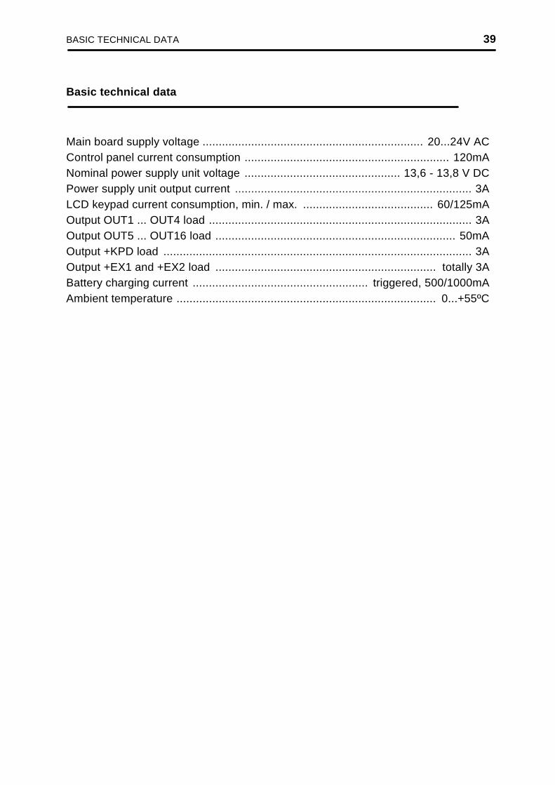
BASIC TECHNICAL DATA 39
Basic technical data
Main board supply voltage .................................................................... 20...24V AC Control panel current consumption ............................................................... 120mA Nominal power supply unit voltage ................................................ 13,6 - 13,8 V DC Power supply unit output current ......................................................................... 3A LCD keypad current consumption, min. / max. ........................................ 60/125mA Output OUT1 ... OUT4 load ................................................................................. 3A Output OUT5 ... OUT16 load .......................................................................... 50mA Output +KPD load ............................................................................................... 3A Output +EX1 and +EX2 load .................................................................... totally 3A Battery charging current ...................................................... triggered, 500/1000mA Ambient temperature ................................................................................ 0...+55ºC

40 System description and installation CA-64 SATEL
SATEL s.c.
80-172 Gdańsk; POLAND ul. Schuberta 79
tel. (58) 32 09 400; (39) 12 47 27 Technical Department (58) 32 09 420; (604) 166 075
www.satel.pl [email protected]


![Part 10: Time Series Applications [ 1/64] Econometric Analysis of Panel Data William Greene Department of Economics Stern School of Business.](https://static.fdocuments.in/doc/165x107/56649d365503460f94a0dc13/part-10-time-series-applications-164-econometric-analysis-of-panel-data.jpg)