Control of Whirling of A Rotating Shaft Using …€¦ · Proceedings of the 1st International and...
7
Proceedings of the 1 st International and 16 th National Conference on Machines and Mechanisms (iNaCoMM2013), IIT Roorkee, India, Dec 18-20 2013 Control of Whirling of A Rotating Shaft Using HSLDS Mountings Siddhartha Bhowmick Department of Mechanical Engineering Kanksa Academy of Technology and Management, TIG Durgapur, W.B.-713148, India [email protected] Ranjan Kumar Mitra and Atul Krishna Banik Department of Mechanical Engineering National Institute of Technology, Durgapur W.B.-713209, India [email protected] [email protected] Abstract— In rotating machineries vibration causes various problems. The moving parts get fatigued, greater wear and noise formation takes place, undue vibration is transmitted to the supporting frame or base foundation etc. The predominant cause of this vibration is unbalanced forces. To reduce the rotor’s response, the machine is mounted on HSLDS (high-static-low dynamic-stiffness) mechanism as proposed in this paper. Like an equivalent linear support its static stiffness is same but at the same time, it offers a lower dynamic stiffness. So, it has the same capability of carrying the load but has a lower natural frequency compared to a linear counterpart. This is fulfilled by reducing the values of the critical speed and peak whirl amplitude of the rotor, being mounted on HSLDS springs. In this paper the advantages of HSLDS mounts are explained using a 2 DOF model of simple rotary machine. It consists of a rigid disk having a mass ‘m’ and a shaft, bearings, supports which are flexible but has negligible mass. To present the advantages of dynamic stiffness with low value, a linear analysis is done for small deflection of the rotor from its static equilibrium position; in case of large displacement, a nonlinear equation of motion is formed and solved using two terms harmonic balance method in MATLAB. The usefulness of the HSLDS supports is shown by plotting the responses of the rotor with linear and HSLDS mounts simultaneously. Last but not the least, the problems due to strong nonlinearity (hardening HSLDS mechanism) is depicted. Keywords—rotating machines; HSLDS mounts; low critical speed; whirling. I. INTRODUCTION The whirling of a rotating shaft occurs due to an eccentric centre of mass of the rotor with respect to its geometrical centre. The dynamic response of rotating machinery due to rotating unbalance is discussed elaborately [1-5]. Here an attempt is made to explore the nonlinear features of a modeled HSLDS support due to which the rotating shaft whirls with reduced amplitude. In this paper, the objective is to run the high speed rotor steadily by reducing the machine’s own natural frequency of vibration so that the operating speeds are far beyond the critical speeds as quickly as possible. The suspension systems with low natural frequencies have several usages; one of them is the vibration isolation where a large static displacement is prevented by providing a high static stiffness. For this reason, HSLDS mounts are useful from isolation perspective. In this paper, a model of HSLDS springs supported rotating machine is considered and is subjected to a harmonic unbalanced force. It is shown that the critical speed is reduced by using the HSLDS support; consequently, the amplitude of vibration during whirling is reduced as well. At first, the usefulness of low stiffness (dynamic) in case of linear mounts is discussed. Thereafter, the HSLDS mounts are introduced and the dynamic responses of the rotor are obtained during small oscillations and large oscillations from its static equilibrium position. Finally, the advantages and limitations of using nonlinear HSLDS springs are stated. II. LINEAR MOUNT A rotary machine, having two degree of freedom, is modeled by considering a rotor (rigid) mounted on supports (flexible) [3, 5]. The exciting unbalanced force applied at the rotor’s centre will cause only the translational motion as the machine is considered to be symmetrical and the assumed masses of flexible supports along with the shaft are negligible. Fig.1.1 shows schematic diagram of the modeled machine, where the concentrated mass is located on the disk which is placed mid-way on the shaft. Fig.1.1 Schematic diagram of the shaft-disk model: Initial state with solid line and whirling state with dashed line. 294
Transcript of Control of Whirling of A Rotating Shaft Using …€¦ · Proceedings of the 1st International and...

Proceedings of the 1st International and 16th National Conference on Machines and Mechanisms (iNaCoMM2013), IIT Roorkee, India, Dec 18-20 2013
Control of Whirling of A Rotating Shaft Using HSLDS Mountings
Siddhartha Bhowmick Department of Mechanical Engineering
Kanksa Academy of Technology and Management, TIG Durgapur, W.B.-713148, India
Ranjan Kumar Mitra and Atul Krishna Banik Department of Mechanical Engineering
National Institute of Technology, Durgapur W.B.-713209, India
[email protected] [email protected]
Abstract— In rotating machineries vibration causes various problems. The moving parts get fatigued, greater wear and noise formation takes place, undue vibration is transmitted to the supporting frame or base foundation etc. The predominant cause of this vibration is unbalanced forces. To reduce the rotor’s response, the machine is mounted on HSLDS (high-static-low dynamic-stiffness) mechanism as proposed in this paper. Like an equivalent linear support its static stiffness is same but at the same time, it offers a lower dynamic stiffness. So, it has the same capability of carrying the load but has a lower natural frequency compared to a linear counterpart. This is fulfilled by reducing the values of the critical speed and peak whirl amplitude of the rotor, being mounted on HSLDS springs. In this paper the advantages of HSLDS mounts are explained using a 2 DOF model of simple rotary machine. It consists of a rigid disk having a mass ‘m’ and a shaft, bearings, supports which are flexible but has negligible mass. To present the advantages of dynamic stiffness with low value, a linear analysis is done for small deflection of the rotor from its static equilibrium position; in case of large displacement, a nonlinear equation of motion is formed and solved using two terms harmonic balance method in MATLAB. The usefulness of the HSLDS supports is shown by plotting the responses of the rotor with linear and HSLDS mounts simultaneously. Last but not the least, the problems due to strong nonlinearity (hardening HSLDS mechanism) is depicted.
Keywords—rotating machines; HSLDS mounts; low critical speed; whirling.
I. INTRODUCTION
The whirling of a rotating shaft occurs due to an eccentric centre of mass of the rotor with respect to its geometrical centre. The dynamic response of rotating machinery due to rotating unbalance is discussed elaborately [1-5]. Here an attempt is made to explore the nonlinear features of a modeled HSLDS support due to which the rotating shaft whirls with reduced amplitude.
In this paper, the objective is to run the high speed rotor steadily by reducing the machine’s own natural frequency of vibration so that the operating speeds are far beyond the critical speeds as quickly as possible. The suspension systems with low natural frequencies have several usages; one of them is the vibration isolation where a large static displacement is prevented by providing a high static stiffness. For this reason, HSLDS mounts are useful from isolation perspective. In this paper, a model of HSLDS
springs supported rotating machine is considered and is subjected to a harmonic unbalanced force. It is shown that the critical speed is reduced by using the HSLDS support; consequently, the amplitude of vibration during whirling is reduced as well. At first, the usefulness of low stiffness (dynamic) in case of linear mounts is discussed. Thereafter, the HSLDS mounts are introduced and the dynamic responses of the rotor are obtained during small oscillations and large oscillations from its static equilibrium position. Finally, the advantages and limitations of using nonlinear HSLDS springs are stated.
II. LINEAR MOUNT
A rotary machine, having two degree of freedom, is modeled by considering a rotor (rigid) mounted on supports (flexible) [3, 5]. The exciting unbalanced force applied at the rotor’s centre will cause only the translational motion as the machine is considered to be symmetrical and the assumed masses of flexible supports along with the shaft are negligible. Fig.1.1 shows schematic diagram of the modeled machine, where the concentrated mass is located on the disk which is placed mid-way on the shaft.
Fig.1.1 Schematic diagram of the shaft-disk model: Initial state with solid line and whirling state with dashed line.
294

Proceedings of the 1st International and 16th National Conference on Machines and Mechanisms (iNaCoMM2013), IIT Roorkee, India, Dec 18-20 2013
Fig.1.2 Elevation of the whirling shaft-disk model: Eccentricity ‘e’ is the distance between the centre of mass of the disk, G, and the geometrical centre of the rotor, S.
The dynamics of the shaft-disk system has been
studied by analyzing the motion of the rigid disk’s centre S in the x-y plane. The axially symmetric shaft and the flexible supports have negligible masses and the gyroscopic forces is made zero by neglecting the disk’s rotation. Also, the supports are assumed to have no coupling between the x and y directions and the equations representing the motion along two directions are decoupled fully. Thus, the actual system is substituted by two separate systems in the x and y coordinates, each having single degree of freedom (SDOF). The total stiffness (i.e. those of the supports and the shaft) of the linear springs is xk and yk in the x and y directions and
they may be different also. Viscous damping is assumed
with coefficients ,xc yc and modeled by dashpots.
Resolving the forces in x direction, we have
.))cos((2
2
dt
dxcxktex
dt
dm xx −−=+ ω
Resolving the forces in y direction, we have
.))sin((2
2
dt
dycyktey
dt
dm yy −−=+ ω
Then the system’s equations of motion are
),cos(2 tmekxxcxm ωω=++ ɺɺɺ (1.1a)
),sin(2 tmekyycym ωω=++ ɺɺɺ (1.1b)
where m is the disk’s mass and the centre of mass is offset by the eccentricity ‘e’ with respect to the centre of rotation. At t = 0, the eccentricity is made in the positive x direction after selecting the phase reference accordingly.
In terms of the displacement u (dimensional quantity), the generic equation is
).cos(2 tmekuucum ωω=++ ɺɺɺ (1.2)
Non-dimensional form of this equation is
),cos(2 2 τζ lll vvv ΩΩ=+′+′′ (1.3)
where
.,,2,, 2nllnlnllnl mkmcteuv ωωωωζωτ =Ω====
The various parameters of the linear system are denoted by the subscript l.
The solution of (1.3) is the response of the disk with linear mounts for a specific frequency [1, 2]. The functional relationship of non-dimensional amplitude
)( maxv with the frequency ratio )( lΩ is shown by the
dashed-dotted line in Fig.2.5. Only small displacements of the shaft occur about its static equilibrium position during lower speeds )1( <<Ω l and also spinning of the disk takes
place about its geometrical centre. The maximum amplitude of vibration occurs at the following frequency ratio
1for ,121
12
<<≈−
=Ω l
l
l ζζ
(1.4)
and the corresponding response amplitude is
.1for ,2
1
212
1l
2max <<≈
−= ζ
ζζζ lll
v (1.5)
This rotational speed of the shaft, for which the response amplitude reaches its maximum, is called the critical speed [2]. At high rotational speeds )1( >>Ωl ,
euv = tends to 1 i.e. the shaft tends to be displaced by
an amount equal to the eccentricity ‘e’ and the disk spins about its centre of mass. This phenomenon is referred to as whirling of shaft and for the isotropic supports, the motion of the whirling shaft traces out a circular orbit. Generally, if the stiffness’s of vertical and horizontal supports are different, the shaft traces out an elliptical orbit [2, 4, 5 and 6].
III. HSLDS MOUNT
In a nonlinear suspension system, the low dynamic stiffness of HSLDS (high-static-low-dynamic-stiffness) springs brings down the natural frequency of oscillations without affecting static displacement [7, 8] as well. Here, we have considered a system consisting of parallel connected springs of negative and positive stiffness; two inclined springs with same coefficients 0k
acting as ‘negative’ stiffness elements (softening characteristics) connected in parallel to a vertical spring of ‘positive’ stiffness vk ( hardening characteristics).
Fig.2.1 Representation of a HSLDS mechanism schematically: At the static equilibrium position the (maximum) negative stiffness from the inclined springs is balanced exactly by the positive stiffness of the vertical spring.
295
Proceedings of the 1st International and 16th National Conference on Machines and Mechanisms (iNaCoMM2013), IIT Roorkee, India, Dec 18-20 2013
There is a unique relationship between the geometry, being designated by the geometrical parameter
00 cosθγ == La and the stiffness of the springs, being
designated by the spring coefficient ratio vkk0=λ ; it
yields a system with quasi-zero dynamic stiffness at the static equilibrium position. The dynamic stiffness increases monotonically with displacement on either side of the equilibrium position, and this is least severe when the oblique springs are inclined initially at an angle between 48°and 57° approximately.Non-dimensional spring force is given by
,1)1ˆ12ˆ()ˆ1(2ˆˆ 21222
0
−+−−−−+== −uuuuLk
ff
v
γγλ (2.1)
where .10,ˆ 0 <<= γLuu The non-dimensional stiffness of the system is found
out by differentiating (2.1) with respect to the displacement as
,)1ˆ12ˆ(
121ˆ2322
2
+−−−+==
uuk
KK
v γ
γλ (2.2)
whereK is the dimensional stiffness of the system. At a unique intermediate angle of inclination, being
represented byQZSγ , there is a stationary point of
inflexion which corresponds to a stable equilibrium position with zero stiffness. This occurs at the static equilibrium position at which the (maximum) negative stiffness from the inclined springs is balanced exactly by the positive stiffness of the vertical spring. If (2.2) is
evaluated at the static equilibrium position 21ˆ γ−=eu
and set to zero, then the value ofQZSγ , that gives the
quasi-zero-stiffness, is given by
12
2
+=
λλγ QZS , for given value ofλ . (2.3a)
Equivalently, the value of λ that ensures QZS behavior is
,)1(2 γ
γλ−
=QZS for given value of γ . (2.3b)
By enforcing the QZS condition (2.3a) in (2.1), we have
+−−−
−+=
2322
2
)1ˆ12ˆ(1
11ˆ
uuK
QZS
QZS
QZS
QZSQZS
γ
γγ
γ (2.3c)
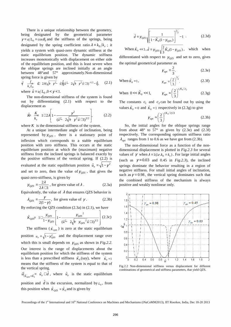
The stiffness (QZSK ) is zero at the static equilibrium
position 21 QZSeu γ−= and the displacement range over
which this is small depends on QZSγ as shown in Fig.2.2.
Our interest is the range of displacements about the equilibrium position for which the stiffness of the system is less than a prescribed stiffness 0K (say), where 1ˆ
0 =K
means that the stiffness of the system is equal to that of the vertical spring.
duu eKKQZS
ˆˆˆ0
ˆˆ +== , where eu is the static equilibrium
position and d is the excursion, normalized by0L , from
this position when 0ˆˆ KKQZS = and is given by
1)1(ˆ1
1ˆ3
2
0
−
−−=
QZSQZS
Kd
γγ . (2.3d)
When 1ˆ0 <<K , )1(ˆ
3
2ˆ0 QZSQZS Kd γγ −= , which when
differentiated with respect to QZSγ and set to zero, gives
the optimal geometrical parameter as
.3
2=optγ (2.3e)
When 1ˆ0 =K , .
3
2 23
=optγ (2.3f)
When ,1ˆ0 0 <<<< K 201
3
2cKc
opt
+
≈γ (2.3g)
The constants 1c and 2c can be found out by using the
values 0ˆ0 =K and 1ˆ
0 =K respectively in (2.3g) to give 1)2( 0
3
2+
≈K
optγ (2.3h)
So, the initial angles for the oblique springs range from about 48° to 57° as given by (2.3e) and (2.3f) respectively. The corresponding optimum stiffness ratio
optλ ranges from 1 to 0.6 as we have got from (2.3b).
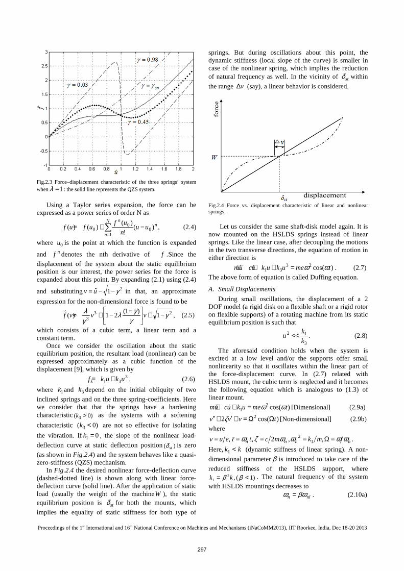
The non-dimensional force as a function of the non-dimensional displacement is plotted in Fig.2.3 for several values of γ when ). .( 1 0 vkkei ==λ . For large initial angles
(such as 03.0=γ and 0.45 in Fig.2.3), the inclined
springs dominate the behavior resulting in a region of negative stiffness. For small initial angles of inclination, such as 98.0=γ , the vertical spring dominates such that
the combined stiffness of the mechanism is always positive and weakly nonlinear only.
Fig.2.2 Non-dimensional stiffness versus displacement for different combinations of geometrical and stiffness parameters, that yield QZS.
296
Proceedings of the 1st International and 16th National Conference on Machines and Mechanisms (iNaCoMM2013), IIT Roorkee, India, Dec 18-20 2013
Fig.2.3 Force–displacement characteristic of the three springs’ system when 1=λ : the solid line represents the QZS system.
Using a Taylor series expansion, the force can be
expressed as a power series of order N as
,)(!
)()()( 0
1
00
nN
n
n
uun
ufufuf −+= ∑
= (2.4)
where 0u is the point at which the function is expanded
and nf denotes the nth derivative of f .Since the
displacement of the system about the static equilibrium position is our interest, the power series for the force is expanded about this point. By expanding (2.1) using (2.4)
and substituting 21ˆ γ−−= uv in that, an approximate
expression for the non-dimensional force is found to be
,1)1(
21)(ˆ 233
γγ
γλγλ −+
−−+≈ vvvf (2.5)
which consists of a cubic term, a linear term and a constant term.
Once we consider the oscillation about the static equilibrium position, the resultant load (nonlinear) can be expressed approximately as a cubic function of the displacement [9], which is given by
331 ukukfk += , (2.6)
where 1k and 3k depend on the initial obliquity of two
inclined springs and on the three spring-coefficients. Here we consider that that the springs have a hardening characteristic )0( 3 >k as the systems with a softening
characteristic )0( 3 <k are not so effective for isolating
the vibration. If 01 =k , the slope of the nonlinear load-
deflection curve at static deflection position )( stδ is zero
(as shown in Fig.2.4) and the system behaves like a quasi-zero-stiffness (QZS) mechanism. In Fig.2.4 the desired nonlinear force-deflection curve (dashed-dotted line) is shown along with linear force-deflection curve (solid line). After the application of static load (usually the weight of the machineW ), the static equilibrium position is stδ for both the mounts, which
implies the equality of static stiffness for both type of
springs. But during oscillations about this point, the dynamic stiffness (local slope of the curve) is smaller in case of the nonlinear spring, which implies the reduction of natural frequency as well. In the vicinity of stδ within
the range v∆ (say), a linear behavior is considered.
Fig.2.4 Force vs. displacement characteristic of linear and nonlinear springs. Let us consider the same shaft-disk model again. It is now mounted on the HSLDS springs instead of linear springs. Like the linear case, after decoupling the motions in the two transverse directions, the equation of motion in either direction is
)cos(2331 tmeukukucum ωω=+++ ɺɺɺ . (2.7)
The above form of equation is called Duffing equation.
A. Small Displacements
During small oscillations, the displacement of a 2 DOF model (a rigid disk on a flexible shaft or a rigid rotor on flexible supports) of a rotating machine from its static equilibrium position is such that
.3
12
k
ku << (2.8)
The aforesaid condition holds when the system is excited at a low level and/or the supports offer small nonlinearity so that it oscillates within the linear part of the force-displacement curve. In (2.7) related with HSLDS mount, the cubic term is neglected and it becomes the following equation which is analogous to (1.3) of linear mount.
)cos(21 tmeukucum ωω=++ ɺɺɺ [Dimensional] (2.9a)
)cos(2 2 tvvv ΩΩ=+′+′′ ζ [Non-dimensional] (2.9b)
where
.,,2,, 12
nnnn mkmcteuv ωωωωζωτ =Ω====
Here, kk <1 (dynamic stiffness of linear spring). A non-
dimensional parameterβ is introduced to take care of the
reduced stiffness of the HSLDS support, where)1(,2
1 <= ββ kk . The natural frequency of the system
with HSLDS mountings decreases to
nln βωω = . (2.10a)
297

Proceedings of the 1st International and 16th National Conference on Machines and Mechanisms (iNaCoMM2013), IIT Roorkee, India, Dec 18-20 2013
βlΩ=Ω∴ (2.10b)
This reduced natural frequency of the system causes the damping ratio to increase, whose expression is given by
βζζ l= (2.11)
Moreover, the amplitude of vibration is decreased during a specific working speedω . The non-dimensional frequency response is
2222
2max
max4)1( Ω+Ω−
Ω==ζe
uv . (2.12)
We have used MATLAB program to plot the functional relationship of non-dimensional amplitude
)( maxv with the frequency ratio )( lΩ of the linear system
with a damping ratio )( lζ of 0.75% and compared with
the frequency response of the system with HSLDS mountings when .5.2,01875.0,4.0 lΩ=Ω== ζβ
It is seen that the peak amplitude of the rotating system is less for HSLDS mounts and the corresponding frequency (the critical speed) [2], at which the peak occurs, is less as well. In other words, when the rotating shaft is supported on HSLDS springs, both the peak whirl amplitude and the critical speed are reduced, provided the response oscillations are small. This is shown in Fig.2.5.
Fig.2.5 Comparison for a system during small oscillations: rotor mounted on HSLDS springs (solid) and on linear springs (dashed-dotted).
B. Large Displacements
The linear theory is valid if 3
12
k
ku << as given by
(2.7). When this is not satisfied during oscillations i.e. oscillations exceed this limit, the dynamics of motion can be rewritten in non-dimensional form as
)cos(2 23 tvvvv ΩΩ=++′+′′ αζ (2.13)
where
.,,,2, 12
312 kekmkmct nnnn ==Ω=== αωωωωζωτ
It is worthwhile to mention that the natural frequency
of the HSLDS mechanism during approximated linear
oscillation is nω . During large oscillations, the amount of
nonlinearity and its nature (hardening or softening) are taken into account by the coefficient of the nonlinear termα .
Two Terms Harmonic Balance (HB) method is used for solving the differential equation (2.13) with nonlinear characteristics. It should be noted that the terms related with the fundamental frequency only are taken in the calculation. This is possible by considering the periodic response of the system and when the responses at higher order harmonics and sub-harmonics are negligible compared to the excitation frequency response. Applying the harmonic balance method [10], (2.13) becomes a cubic equation in terms of the square of the amplitude R at a given frequency ratioΩ .
04)1()75.0)(1(2)75.0( 42222224226 =Ω−Ω+Ω−+Ω−+ ζαα RRR (2.14) The above polynomial equation of amplitude R is
solved and plotted to show the advantages of using HSLDS mounts over the linear mounts and the problems of using hardening HSLDS mechanism for a continuous range of normalized linear frequency lΩ in Fig.2.6 and in
Fig.2.7 respectively. It should be noted that if α is set to zero, then solving
for R in (2.14), the response of the HSLDS system during small displacement of the rotor, as given by (2.12), is obtained.
In Fig.2.6 the frequency on the horizontal axis is normalized by the frequency, ,lΩ of the linear system. For
the linear system, the damping ratio 0075.0=lζ and the
scaling factor 4.0=β are used. So, the damping ratio of
the HSLDS isolator is 01875.0=ζ and the coefficient of
nonlinearity term 410−=α is considered. We have used numerical integration (NI) method
(ode23 in MATLB) also to validate the plot of non-dimensional amplitude (maxv ) as a function of the
frequency ratio ( lΩ ), which is obtained by the harmonic
balance (HB) method. Carrella [10] discussed the useful details related with
the applications of rotating machines in his dynamic analysis comprehensively. In Fig. 2.6 the solid and dashed line, showing the frequency response of the system, is obtained by solving for Ω in (2.14). When the nonlinear coefficientα and the damping ratio ζ are subjected to the following conditions:
,)316( 2ζα < (2.15a)
,12 <<ζ (2.15b) then the maximum value of amplitude )( maxv is
,316
22
maxαζ −
≈v (2.16a)
which occurs at the frequency [11]
298

Proceedings of the 1st International and 16th National Conference on Machines and Mechanisms (iNaCoMM2013), IIT Roorkee, India, Dec 18-20 2013
.316
42 αζ
ζ
−≈Ωd (2.16b)
If the rotational speed Ω be increased abovedΩ , then
the response amplitude jumps down to lower value suddenly.
Fig.2.6 System responses are compared: a linear spring mount (dash-dot) and a HSLDS mount (solid-dash). In FRF of HSLDS mount, steady state unstable solutions are denoted by the dashed part.
Fig.2.6 shows the two response curves of the same system representing linear and HSLDS mounts and are plotted on the same graph with the same frequency ratio for comparison. As the natural frequency of the linear model normalizes the rotational speed along the horizontal axis, for the linear system the peak occurs at 1=Ωl . It
should be noted that as the damping coefficient c is maintained constant throughout, so the HSLDS system has the damping ratio of 01875.0=βζ l . Readily (1.5)
and (2.16a) provide us the values of peak amplitudes of the linear system and the HSLDS system respectively. For the linear system, the maximum response is
,67.66)2(1max, =≈ llv ζ whilst that for the HSLDS
system is .41.27max =v
Thus, the reduced amplitude of maximum response and the occurrence of resonance at a lower frequency are the advantages of employing the HSLDS spring system.
C. Hardening HSLDS Mechanism
Fig.2.7 shows the nonlinear response curve of a hardening HSLDS mechanism with a different value of,α where it is compared with the linear model’s dynamic response as well. It shows the dynamic response when
limαα = . It is seen that by increasing,α the peak value
of the system’s response with HSLDS mounts can be equal )( limαα = or even beyond )( limαα > that of a
linearly supported system. So, while designing the HSLDS mounts one must be careful about the leaning nature of the response curve towards right as the system is hardening. Otherwise, it is immaterial to use HSLDS mounts instead of the simpler linear mounts. To limit the
value of the coefficient α of the cubic term, equality is imposed between (1.5) and (2.16a) which yields
).1(3
16 22lim βζα −= (2.17)
Fig.2.7 Comparison between a hardening HSLDS isolator (solid-dash) and an equivalent linear mount mechanism (dash–dot) in terms of frequency response.
Figure 2.7 shows the nonlinear response curve for a hardening HSLDS mechanism with ,001575.0lim == ααas calculated from (2.17) with 01875.0=ζ , 4.0=β .When
limαα = , the jump-down frequency becomes equal to the
natural frequency of the equivalent linear model and the peak amplitude of the HSLDS system becomes equal to that of an equivalent linear system as well.
IV. DISCUSSIONS
The potentiality of HSLDS springs for mounting the rotating machineries is presented by analyzing a simple model of a rotary machine with simulation in this paper. Application of HSLDS mount to any rotating machine will cause low natural frequencies of vibration inevitably due to its low dynamic stiffness. The machine dynamics can be analyzed well when the working speed is below the first elastic mode of the rotor which occurs very often. This analysis would have become more vivid if the degree of freedom related to disk rotation and the gyroscopic effects are considered. Likewise a bouncing and tilting motion may occur if the disk is not placed centrally and mid-way between the two identical supports (non-symmetric rotor). Irrespective of these complicacies, in this paper probable benefits are outlined, especially when the rotor with HSLDS mounts are operated well above the critical speeds. For this purpose, we have given a pragmatic view of the rotor’s response with linear and HSLDS mounts side by side. Nevertheless, due to less dynamic stiffness and reduced response, the machine mounted on HSLDS springs transmits less force to the foundations.
The support system is not designed in detail in this work. For instance, if a flexible coupling is used to separate the rotor from the motor, it would cause
299

Proceedings of the 1st International and 16th National Conference on Machines and Mechanisms (iNaCoMM2013), IIT Roorkee, India, Dec 18-20 2013
significant positive stiffness as the coupling would have become an integral part of the support. Prior information regarding the accurate value of the static load is essential, so that one can locate the equilibrium position near the low dynamic stiffness part of the force-deflection characteristic curve of the nonlinear HSLDS springs. Proper compromise is sought between the nonlinear dynamic effects and the static deflection for choosing the amount of nonlinearity. Small damping ratio is considered to make the isolation good. Care must be taken to keep the transient part of vibrations as short as possible and to run the machine through the critical speed as quickly as possible.
Realizing the characteristic of nonlinear stiffness, an arrangement of springs is shown in Fig.2.1, which can exhibit the required stiffness. Other possible arrangements of elastic elements were considered by Alabuzhev et al. [7]. Work is going on tailoring of bi-stable composite structures to produce the required stiffness characteristic [12].
Despite few practical issues to look into, the usefulness of HSLDS mounts for controlling the vibration of rotating machinery has immense potentiality.
CONCLUSION
At first, a simple model of unbalanced symmetric rotating machine, having two degree of freedom and mounted on linear springs, has been analyzed from vibration isolation point of view. Thereafter, HSLDS (high-static-low-dynamic stiffness) mounts, having nonlinear characteristics, were used to bring down the natural frequency of the vibrating rotary system. The ultimate effect is the lowering of the critical speeds well below the working speed with the sufficient control over the whirling of the rotating shaft. The analytical nonlinear equation of motion was formulated and solved for this purpose. The advantages of using HSLDS springs are shown by comparing the various system-responses plot wise. At last, the impact of strong nonlinearity due to rotating unbalance has been pointed out.
REFERENCES
[1] A. Tondl , Some Problems of Rotor Dynamics, Chapman & Hall,
London,1965.
[2] G.Genta, Vibration of Structures and Machines: Practical Aspects, Springer, Berlin,1995.
[3] J.P.Den Hartog, Mechanical Vibrations, fourth ed., Dover, NewYork,1985.
[4] S.S.Rao, Mechanical Vibrations, fourth ed., Dover, NewYork,1985.
[5] L.Meirovitch, Elements of Vibration Analysis, international ed., McGrawHill, NewYork, 1986.
[6] D.J. Ewins, Modal Testing, second ed., Research Studies Press, 2000.
[7] P. Alabuzhev, A. Gritchin, L. Kim, G. Migirenko, V. Chon, P. Stepanov, Vibration Protecting and Measuring Systems with Quasi-Zero Stiffness, Hemisphere, NY, 1989.
[8] E. Rivin, Passive Vibration Isolation, AP, 2001.
[9] A. Carrella, M.J. Brennan, T.P. Waters, Static analysis of a passive vibration isolator with quasi-zero-stiffness characteristic, Journal of Sound and Vibration 301 (3–5) (2007) 678–689.
[10] A. Carrella, Passive vibration isolators with high-static-low-dynamic-stiffness, Ph.D. Thesis, University of Southampton, ISVR, 2008.
[11] M.J. Brennan, I. Kovacic, A. Carrella, T.P.Waters, On the jump-up and jump-down frequencies of the duffing oscillator, Journal of Sound and Vibration 318 (4–5) (2008) 1250–1261.
[12] F.Mattioni, P.M.Weaver, K.D.Potter, M.I.Friswell, Analysis of thermally induced multi stable composites, International Journal of Solids and Structures45(2)(2008)657–675.
300