Control of Thermoacoustic Instabilities: Actuator-Sensor Placement Pushkarini Agharkar, Priya...
18
Control of Thermoacoustic Instabilities: Actuator-Sensor Placement Pushkarini Agharkar, Priya Subramanian, Prof. R. I. Sujith Department of Aerospace Engineering Prof. Niket Kaisare Department of Chemical Engineering Indian Institute of Technology, Madras Acknowledgements: Boeing Travel Grant, IIT Madras Alumni Affairs Association, IIT Madras
-
Upload
griffin-chase -
Category
Documents
-
view
215 -
download
1
Transcript of Control of Thermoacoustic Instabilities: Actuator-Sensor Placement Pushkarini Agharkar, Priya...

Control of Thermoacoustic Instabilities:Actuator-Sensor Placement
Pushkarini Agharkar, Priya Subramanian, Prof. R. I. SujithDepartment of Aerospace EngineeringProf. Niket KaisareDepartment of Chemical Engineering
Indian Institute of Technology, Madras
Acknowledgements: Boeing Travel Grant, IIT MadrasAlumni Affairs Association, IIT Madras

Thermoacoustic Instabilities
Occur due to positive feedback mechanism between combustion and acoustic subsystems
Representative system:
ducted premixed flame
Schuller (2003)
Acoustics
Heat Release

Modelof the ducted premixed flame
Control Framework • LQ Regulator
• Kalman filterActuator Placement
•LMI based techniques
•based on Hankel singular valuesConclusions

Model of the ducted premixed flame
• acoustic subsystem
• combustion subsystem
• single actuator and sensor pair
• actuator adds energy to the system
• sensor measures acoustic pressure
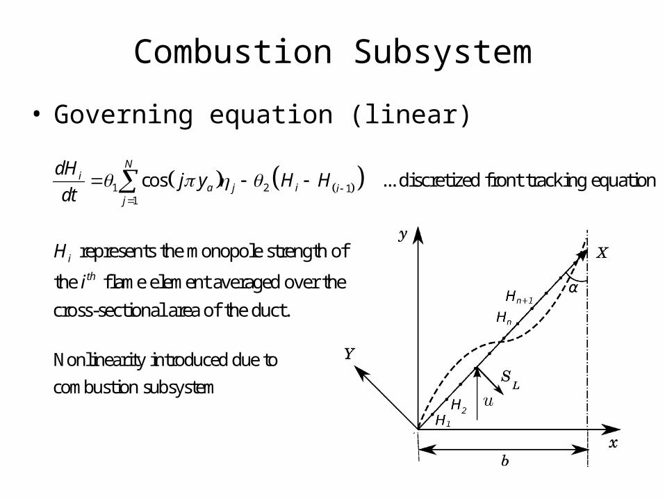
• Governing equation (linear)
Combustion Subsystem
1 2 11
cos ... discretized front tracking equationN
ia j i i
j
dHj y H H
dt
represents the monopole strength of
the flame element averaged over the
cross-sectional area of the duct.
i
th
H
i
Nonlinearity introduced due to
combustion subsystem

Acoustic Subsystem
• Governing equations:
1
...momentum
2 2 sin ...energy
2
j
P
j j f ii
dj
dt j
dj j j y H
dt j
sincaj y u
M
contribution from controller
fluctuating heat release
1
1
acoustic velocity cos
acoustic pressure sin
N
jj
N
jj
u j y t
Mp j y t
j

Properties of the Model
– Non-normality: due to coupling between combustion and acoustic subsystems
– Nonlinearity: due to the equations of evolution of the flame front
– Motivation: Reducing the transient growth and avoiding triggering

State-Space Representation
1
1 2 11
2 2 2 sin sin
cos
j
Pc
j j f i ai
Ni
a j i ij
dj
dt j
dj j j y H j y u
dt j M
dHj y H H
dt
=d
dt
A B u

u K
2
2 2
1 1
N Pj
j ij i
T
jJ t H t
j
is minimized.
Tcl u u
such that the cost functional
Linear Quadratic (LQ) Regulator

Linear Quadratic (LQ) Regulator
u K
Open loop plant :(without control)
dA
dt
dA Bu
dtA BK
Closed loop plant :
(with control)
cA

LMI optimization problem
dA Bu
dtA BK
variables: , cP
is the upper bound on the
energy of the plant
controlled using the LQ
Regulator
c
T
min :
0 0
c
H Hc c
c
PA A P P P
I P I
- Linear Matrix Inequalities (LMI): inequalities defined for matrix variables
cA

Actuator Placement using LMI based Optimization Techniques
10cl
max
* Actuator located closer to flame
results in lower bounds on c E
* This feature is highlighted when
the controller is aggressive ( 1)cl
1cl

Controllability–Observability Measures
• Other ways to determine optimal placement of actuators and sensors
• Controllability-Observability measure based on Hankel singular values (HSVs).
– measure =
– Hankel singular value
2
ii

Controllability–Observability Measures• Measure of controllability-
observability based on HSVs calculated for various actuator and sensor locations
• Locations of the antinodes of the third acoustic pressure mode give highest measure
• From numerical simulations, the third acoustic mode is also the highest energy state

The techniques give contradictory results
Antinodes of the least
stable modes
Measures based on HSVs.
Locations closer to the
flame
LMI based techniques

Actuator Placement Numerical Validation
open loop
0.3
0.5a
a
y
y
In the presence of transient growth, actuators placed according to LMI techniques give better performance than when placed based on HSV measures

Actuator Placement Numerical Validation
0.3
0.5
0.833
In the absence of transient growth, actuators placed according to HSV measures give better performance than in the presence of transient growth, but still not better than LMI techniques.

Conclusions
• Actuator-Sensor placement of non-normal systems requires different approaches than the ones used conventionally.
• For the ducted premixed flame model, actuators placed nearer to the flame give better overall performance.
• Controllers based on these actuators results in low transient growth as well as less settling time.