Control of electric drive
26
Control of electric drive
-
Upload
vijay-krishna -
Category
Engineering
-
view
127 -
download
0
Transcript of Control of electric drive

Control of electric drive
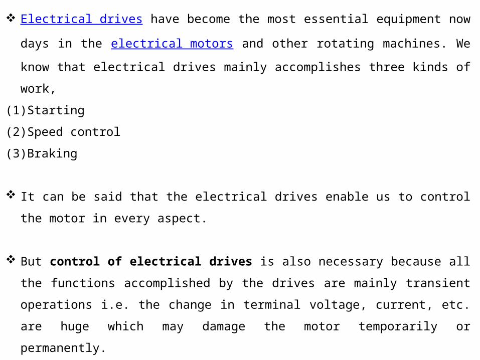
Electrical drives have become the most essential equipment now days in the
electrical motors and other rotating machines. We know that electrical drives mainly
accomplishes three kinds of work,
(1)Starting
(2)Speed control
(3)Braking
It can be said that the electrical drives enable us to control the motor in every aspect.
But control of electrical drives is also necessary because all the functions accomplished by
the drives are mainly transient operations i.e. the change in terminal voltage, current, etc. are
huge which may damage the motor temporarily or permanently.
That’s why the need of controlling the drives rises and there are various methods and
equipment's to control different parameters of the drives which are discussed later.
Modes of operation
An electrical drive operates in three modes
(a) Steady-state(b) Acceleration including starting(c) Deceleration including stopping
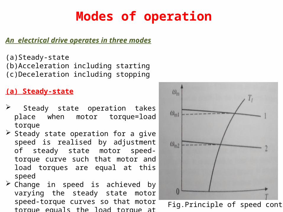
(a) Steady-state
Steady state operation takes place when motor torque=load torque
Steady state operation for a give speed is realised by adjustment of steady state motor speed-torque curve such that motor and load torques are equal at this speed
Change in speed is achieved by varying the steady state motor speed-torque curves so that motor torque equals the load torque at the new desired speed.
Fig.Principle of speed control

(b) Acceleration including starting
Acceleration and deceleration modes are transient operations
Drive operates in acceleration mode whenever a increase in speed is required.
For this motor speed-torque curve must be changed so that motor torque exceeds the load
torque.
Increase in motor torque is accompanied by increase in motor current.
Care must be taken to restrict the motor current with in a value which is safe for both motor
and power modulator.
In applications involving acceleration periods of long duration, current must not be allowed
to exceed the rated value.
When acceleration periods are of short duration a current higher than the rated value is
allowed during acceleration.
In closed loop drives requiring fast response, motor current may be intentionally forced to
the maximum value in order to achieve high acceleration.

(c) Deceleration including stopping
Motor operation in deceleration mode is required when a decrease in its speed is required.
Deceleration occurs when load torque exceeds the motor torque.
Mechanical brakes may be used to produce the required magnitude of deceleration.
Alternatively electric braking may be employed.
Both motor and load torque opposes motion, thus producing larger deceleration .
During electric braking motor current tends to exceed the safe limit.
When electric braking may persists for long periods maximum current is usually
restricted to the rated value.
When electric braking may occur for short duration maximum current is allowed to
exceed the rated value.
Higher the braking torque greater is the deceleration.

Speed control and Drive classification
1. Constant speed drive or single speed drive
Drives where the driving motor runs at a nearly fixed speed
2.Multi speed drive or variable speed drive or Constant torque drive
Drives which operates at discrete speed setting
Speed range of variable speed drives depends on the application
In some applications it can be from rated speed to 10% of rated speed.
In some applications, speed control above rated speed is also desired.
In some applications the speed range is as low as from rated speed to 80% of rated
speed.
3.Multi motor drive
When a umber of motors are fed from a common converter, or when a load is drive by
more than one motor

A variable speed drive is called constant torque drive if the drives maximum torque capability does not change with a change in speed setting. The corresponding mode of operation is called constant torque mode.
A variable speed drive is called constant power drive if the drives maximum power capability does not change with a change in speed setting. The corresponding mode of operation is called constant power mode.
Quality of speed control system is measured interms of speed-regulation which is defined as
speed-regulation %
If open loop control fails to operate to provide the desired speed-regulation drive is operated as closed loop speed control system.
Closed Loop Control of Drives
In electrical drives feedback loops or closed loop control satisfy the following requirements.
•Protection
•Enhancement of speed of response
•To improve steady –state accuracy
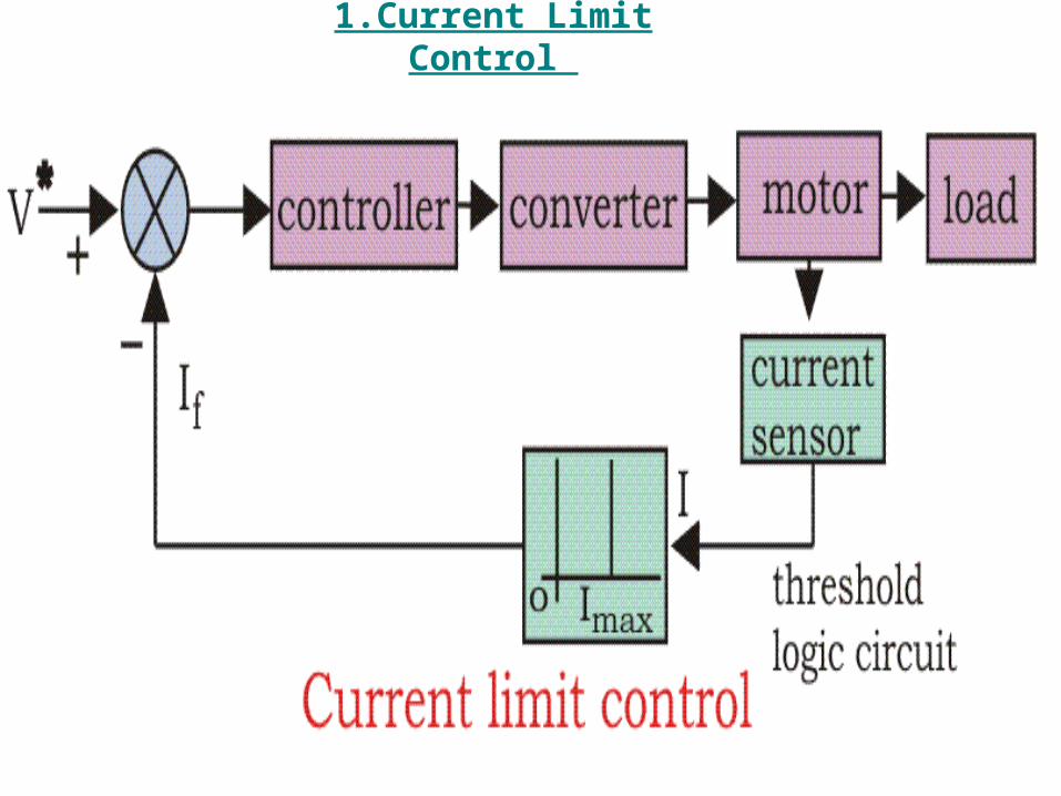
1.Current Limit Control

During the starting, we know if precautionary measures are not taken there is a chance of
huge current flow through the motor circuit.
Current Limit Control scheme is employed to limit the converter and motor current
below a safe limit during transient operations.
It has a current feedback loop with a threshold logic circuit.
To limit the current and sense the current fed to the motor, current limit controller is
installed.
The feedback loop does not effect the normal operation of the drive but if the current
exceeds the predetermined safe limit, the feedback loop activates and the current is
brought down below the safe limit.
Once the current is brought down below the safe limit the feedback loop again
deactivates and in this way the control of current takes place.

2.Closed Loop Torque Control
This type of torque controller is seen mainly in battery operated vehicles like cars,
electric trains etc.
The accelerator present in the vehicles is pressed by the driver to set the reference
torque T*.
The actual torque T follows the T* which is controlled by the driver via accelerator.
Speed feedback loop is present through the driver.
By putting appropriate pressure on the accelerator, driver adjusts the speed depending
on traffic, road codition,his liking, car condition ad speed limit.
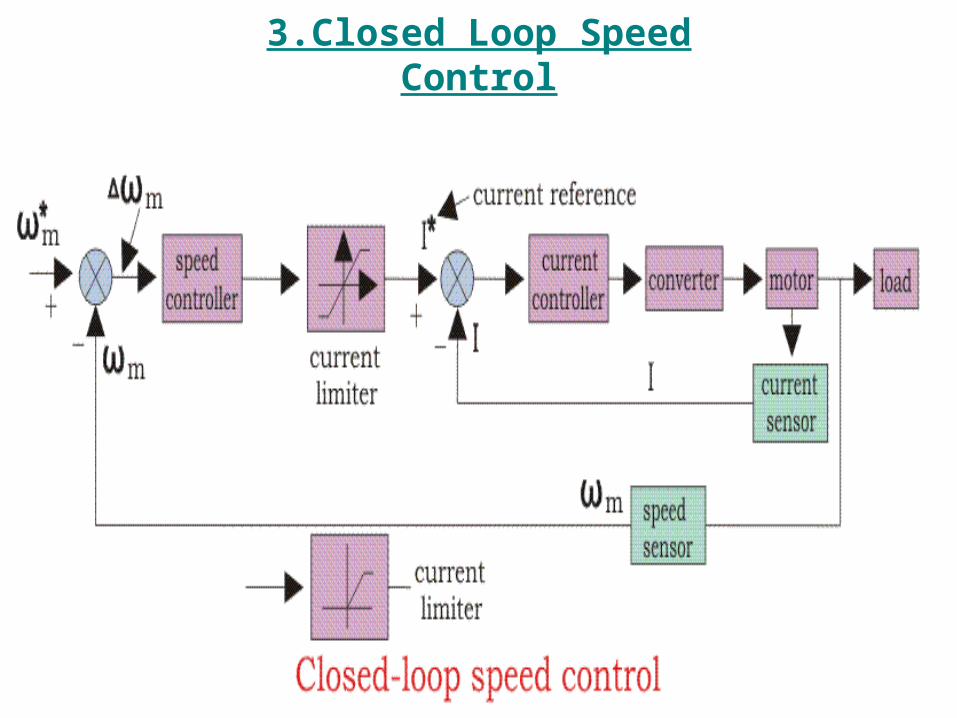
3.Closed Loop Speed Control

Speed control loops are perhaps the most widely used feedback loops for drives.
From the diagram that there are two control loops, which can be said as an inner loop
and outer loop.
The inner current control loop limits the converter and motor current or motor torque
below the safe limit.
Suppose the reference speed Wm* increases and there is a positive error ΔWm, which
indicates that the speed is needed to be increased.
Now the inner loop increases the current keeping it under maximum allowable current.
And then the driver accelerates, when the speed reaches the desired speed then the motor
torque is equal to the load torque and there is a decrease in the reference speed Wm*
which indicates that there is no need of any more acceleration but there must be
deceleration, and braking is done by the speed controller at maximum allowable current.
So, that during speed controlling the function transfers from motoring to braking and
from braking to motoring continuously for the smooth operation and running of the
motor.

4.Closed Loop Speed Control of Multi-motor Drivers
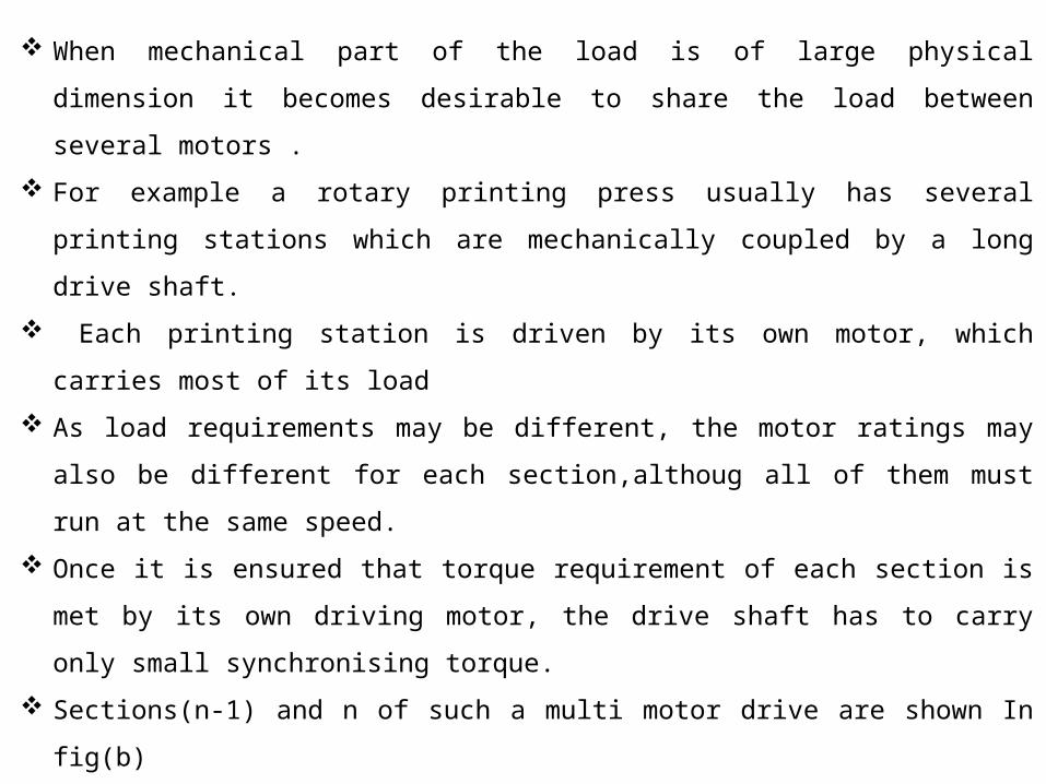
When mechanical part of the load is of large physical dimension it becomes desirable to
share the load between several motors .
For example a rotary printing press usually has several printing stations which are
mechanically coupled by a long drive shaft.
Each printing station is driven by its own motor, which carries most of its load
As load requirements may be different, the motor ratings may also be different for each
section,althoug all of them must run at the same speed.
Once it is ensured that torque requirement of each section is met by its own driving motor,
the drive shaft has to carry only small synchronising torque.
Sections(n-1) and n of such a multi motor drive are shown In fig(b)
Section n is coupled to section (n-1) by clutchCn-1,and so on
A suitable of closed loop speed control scheme is show in fig(a)
It consists of one common outer speed loop and one inner torque control loop for each
section.
As all sections run at same speed, one speed control loop is enough. Speed feedback may be
obtained from suitably placed speed sensor

The common speed controller, through gain constants K1,K2,……..Kn sets reference torques for the closed loop torque control of sections 1,2,…..n respectively.
These type of multi motor drives are also employed in
electric and diesel electric locomotives Rapid transit vehicles Paper machines
Fig(b)

In multi motor drives discussed above various sections of drive are mechanically coupled
through a long shaft.
In other class of multi motor drives, which are employed in continues production processes
various sections are not coupled through a long shaft.
However they get coupled through the material under process as it simultaneously passes
through the sections.
Continuous hot strip rolling mills, fibre spinning mills and paper mills with out mechanical
drive shafts are examples of such multi motor drives.
Below fig depicts an n stand continuous hot strip rolling.
Red hot strip simultaneously passes through all rolling stands.
Rollers of each stand, are driven by its own individual motor,
Various stands which are not mechanically coupled through a long shaft get coupled through
a thin red hot strip which cannot sustain any appreciable forces. Strips must be kept
sufficiently tight in order to avoid folds and crease
As the material passes through a rolling stand its cross section decreases and therefore its
length and velocity increase.
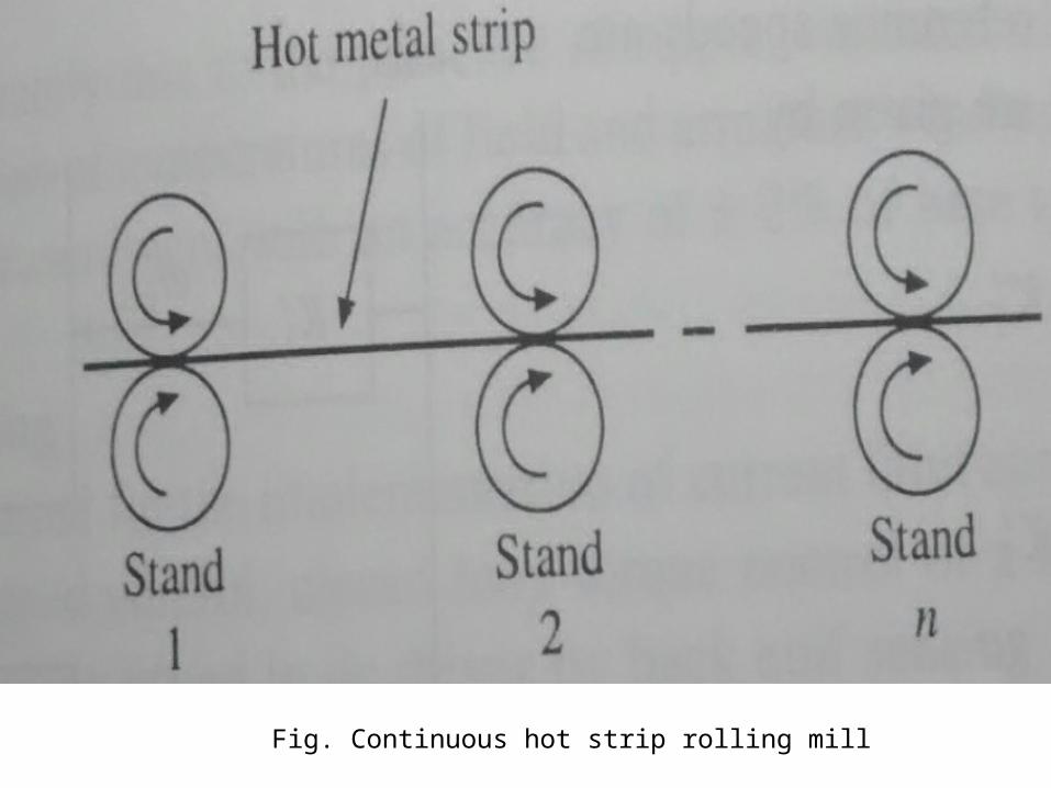
Fig. Continuous hot strip rolling mill
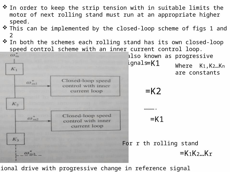
In order to keep the strip tension with in suitable limits the motor of next rolling stand must run at an appropriate higher speed.
This can be implemented by the closed-loop scheme of figs 1 and 2 In both the schemes each rolling stand has its own closed-loop speed control scheme with an
inner current control loop. Fig 1 employs a cascade structure also known as progressive draw to generate speed reference
signals
Fig.1 Sectional drive with progressive change in reference signal
=K1
=K2
=K1
……….
Where K1,K2…Kn are constants
For r th rolling stand
=K1K2…Kr

Fig.2 Sectional drive with parallel reference signal arrangement
=K’1
=K’2
=K’n
…………..
K’1
K’2
K’n are constants

5.Speed sensing
Sensing of speed is required for implementation of closed –loop control scheme
Speed is usually sensed using tachometers coupled to the motor shaft.
A tachometer is an ac or dc generator with a high order of linearity between its speed and
output voltage.
A dc tachometer is built with a permanent magnetic field and some times with silver brushes
to reduce contact drop between the brush and commutator.
Typical voltage outputs are 10V per 1000 rpm.

6.Current sensing
Fig. sensing of current I three-phase ac lines

7.Phase-Locked –Loop (PLL) control
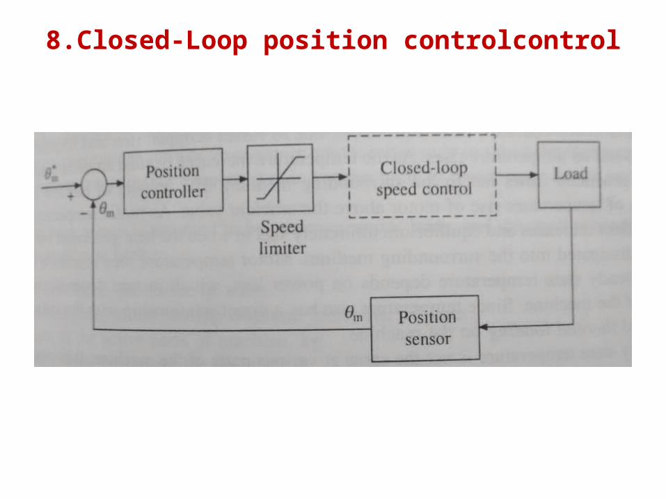
8.Closed-Loop position controlcontrol