CONTROL OF 3-WAY SWITCHES USING CLAP SOUND
50
CONTROL OF 3-WAY SWITCHES USING CLAP SOUND A final project report presented to the Faculty of Engineering By Fiedel Tegar Jiwandono 002201200001 in partial fulfillment of the requirements of the degree Bachelor of Science in Electrical Engineering President University January 2016
Transcript of CONTROL OF 3-WAY SWITCHES USING CLAP SOUND

CONTROL OF 3-WAY SWITCHES USING CLAP SOUND
A final project report
presented to
the Faculty of Engineering
By
Fiedel Tegar Jiwandono
002201200001
in partial fulfillment
of the requirements of the degree
Bachelor of Science in Electrical Engineering
President University
January 2016

President University ii
DECLARATION OF ORIGINALITY
I declare that this final project report, entitled “Control of 3-Way Switches Using Clap
Sound” is my own original piece of work and, to the best of my knowledge and belief, has
not been submitted, either in whole or in part, to another university to obtain a degree. All
sources that are quoted or referred to are truly declared.
Cikarang, Indonesia, January 2016
Fiedel Tegar Jiwandono

President University iii
APPROVAL PAGE
CONTROL OF 3-WAY SWITCHES USING CLAP SOUND
By
Fiedel Tegar Jiwandono
002201200001
Approved by
Dr.-Ing. Erwin Sitompul Antonius Suhartomo, M.Eng.Sc., Ph.D. Final Project Supervisor Head of Study Program
Electrical Engineering
Dr.-Ing. Erwin Sitompul Dean of Faculty of
Engineering

President University iv
ACKNOWLEDGEMENT
Foremost, honor to The Only God, The Most Merciful and The Most Gracious. With full
happiness, I finally finished my thesis. All the efforts and restless night are paid off.
This thesis is dedicated to all people who always give me a lot of support and motivation,
especially for my beloved parents Mr. Purwaluyo and Mrs. Rita Putriani who always concern
about every path that I took.
I would also thank my final project supervisor, Dr. Ing. Erwin Sitompul, for the advise,
guidance, patience and support not only as my final project supervisor but also as a great
lecturer who always pump me to do the best in Electrical Engineering.
Thanks to my senior Muhammad Fikri Arifardi and Kristiantho for the advise and help from
building a neat final project report until the preparation for defense.
Thanks for my fellow friends, Prananda Jalu Akhbar, Yasin Noer Huda, Mawaldi Murandana,
Hartono Mulyo Raharjo, Albert Sebastian, M. Nadif Aswan, who always share the adventures
in this college life.
For Chyntia Ramadina, you will always be in my mind, in my silences, and in my prayers. I
wish that health and success will always be with you. Akeq ubaq ikoq.
Cikarang, January 2016
Fiedel Tegar Jiwandono
President University v
APPROVAL FOR SCIENTIFIC PUBLICATION
I hereby, for the purpose of development of science and technology, certify and approve to
give President University a non-exclusive royalty-free right upon my final project report with
the title:
CONTROL OF 3-WAY SWITCHES USING CLAP SOUND
along with the related software or hardware prototype (if needed). With this non-exclusive
royalty-free right, President University is entitled to conserve, to convert, to manage in a
database, to maintain, and to publish my final project report. These are to be done with the
obligation from President University to mention my name as the copyright owner of my final
project report.
Cikarang, 27 January 2016
Fiedel Tegar Jiwandono
0022012200001
President University vi
ABSTRACT
Nowadays, human always do their job with the help of technology. From securing the house with alarm or even using an RFID card as a train ticket. All of those are build with the intention to make the human life become safer and easier. From that intention, the author comes up with an idea to create a device for human to control the electronic appliances by using clap sound. The resulting switch circuit can be used to turn on and turn off the electronic appliances by means of clap sound. There is no need for the user to come closer to the electronic appliances anymore and physically switch them on. This project concentrates in designing the hardware and the software of the switch circuit. The prototype can identify three different number of claps and is successful to switch on and off three lamps, which represent three different electric or electronic appliances.
Keywords: switch, clap sound, clap switch.

President University vii
TABLE OF CONTENTS
DECLARATION OF ORIGINALITY ....................................................................................... ii
APPROVAL PAGE ................................................................................................................... iii
ACKNOWLEDGEMENT .......................................................................................................... iv
APPROVAL FOR SCIENTIFIC PUBLICATION ..................................................................... v
ABSTRACT ............................................................................................................................... vi
TABLE OF CONTENTS ......................................................................................................... vii
LIST OF FIGURES .................................................................................................................... ix
LIST OF TABLES ...................................................................................................................... x
CHAPTER I INTRODUCTION ................................................................................................. 1
1.1. Final Project Background ................................................................................................. 1
1.2. Problem Statement ............................................................................................................ 1
1.3. Final Project Objective ..................................................................................................... 2
1.4. Final Project Scopes and Limitations ............................................................................... 2
1.5. Final Project Outline ......................................................................................................... 3
CHAPTER 2 DESIGN REQUIREMENT AND SPECIFICATIONS ........................................ 4
2.1. The Proposed Circuit of Clap Switch ............................................................................... 4
2.2. Microcontroller ................................................................................................................. 5
2.2.1. Arduino UNO ............................................................................................................. 7
2.2.2. Arduino UNO pin configuration ................................................................................ 8
2.2.3. Arduino IDE ............................................................................................................. 10
2.3. Sound Sensor .................................................................................................................. 11
2.3.1. Electret Microphone ................................................................................................. 12
2.3.2. LM393 Operational Amplifier ................................................................................. 13

President University viii
2.4. Relay Module .................................................................................................................. 13
2.5. AC/DC Adaptor .............................................................................................................. 15
2.6. Power Outlet ................................................................................................................... 15
CHAPTER 3 DESIGN DEVELOPMENT AND IMPLEMENTATION ................................. 16
3.1. Introduction to the Design Development and Implementation ....................................... 16
3.2. Hardware Implementation .............................................................................................. 18
3.2.1. Hardware Design ...................................................................................................... 19
3.2.2. Arduino UNO Implementation................................................................................. 20
3.3. Software Implementation ................................................................................................ 21
CHAPTER 4 RESULTS AND DISCUSSIONS ....................................................................... 26
4.1. Results ............................................................................................................................. 26
4.2. Discussions ..................................................................................................................... 32
4.3. Strengths and Weaknesses .............................................................................................. 33
CHAPTER 5 CONCLUSIONS AND RECOMMENDATIONS .............................................. 34
5.1. Conclusions ..................................................................................................................... 34
5.2. Recommendations ........................................................................................................... 34
REFERENCES .......................................................................................................................... 36
APPENDIX ............................................................................................................................... 37

President University ix
LIST OF FIGURES
Figure 2.1. Block diagram of the device ..................................................................................... 4
Figure 2.2. Components of microcontroller [2] ........................................................................... 5
Figure 2.3. Principle design of microprocessor [1] ..................................................................... 6
Figure 2.4. Arduino UNO R3 [4] ................................................................................................ 8
Figure 2.5. Arduino UNO pin configurations ........................................................................... 10
Figure 2.6. Arduino IDE 1.0.5 software .................................................................................... 11
Figure 2.7. Sound Sensor FC-04 [5] .......................................................................................... 12
Figure 2.8. Electret Microphone [10] ........................................................................................ 12
Figure 2.9. LM393 Pinout [11] .................................................................................................. 13
Figure 2.8. Relay Module [6] .................................................................................................... 14
Figure 2.9. AC/DC Adaptor ...................................................................................................... 15
Figure 2.10. Broco Power Outlet ............................................................................................... 15
Figure 3.1. V-model [7] ............................................................................................................. 16
Figure 3.2. Block diagram of the device ................................................................................... 17
Figure 3.3. Flow chart of clap switch ........................................................................................ 18
Figure 3.4. Clap switch design .................................................................................................. 19
Figure 3.5. Clap switch prototype ............................................................................................. 20
Figure 3.6. Hardware pin connections ....................................................................................... 21
Figure 4.1. Final project device ................................................................................................. 27
Figure 4.2. Components inside the device ................................................................................. 28
Figure 4.3. Electret microphone in the device ........................................................................... 28
Figure 4.6. Final project device when given input 2 claps ........................................................ 30
Figure 4.7. Final project device when given input 3 claps ........................................................ 31
Figure 4.8. Final project device when given input 4 claps ........................................................ 31
Figure 4.9. Sound sensor works................................................................................................. 32

President University x
LIST OF TABLES
Table 2.1. Types of Memory in Microcontroller ......................................................................... 7
Table 2.2. Electret Microphone Specification [10] ................................................................... 13
Table 2.3. Relay Module Specification ..................................................................................... 14
Table 3.1. Hardware Pin Configurations ................................................................................... 21
Table 3.2. Programming Explanation ........................................................................................ 22

President University 1
CHAPTER I
INTRODUCTION
1.1. Final Project Background
Nowadays, human always use technology in their daily life activities. Technology which
human use can be distinct by its functions, such as for security, for working, for navigating
traffic, for weather forecast, for communication, and many more. All of those technologies
which have been mentioned have the similarity at one point. They are invented to help humans
to do their works and activities become easier and better.
In the automation technology, a machine already can be activated by pressing a button,
wirelessly using Bluetooth in smart phone, by sensing human heat, and many other ways. In
this final project, the idea is to use sound to activate electrical appliances. The final project
device is a switch which can be triggered by a simple sound such as clapping, knocking and a
finger snap sound.
The device is able to solve the problem which related to the efficiency of turning on the lights,
for example when entering a room in the dark. The person can switch the lamp easily without
worrying to step something and even without taking any steps.
1.2. Problem Statement
A busy person sometimes comes home late leaving the room or house in a dark condition.
When the person wants to turn on light in the house, he might have to avoid the obstacles
inside the house. As another example, a patient in a hospital wants to get rest but the television
in the room is still active and there is no nurse that can help the patient to turn off the
television. The solutions of those two examples are to have clap switches which are connected
to the lamp and the television.

President University 2
In this final project report, the author built a clap switch, a switch which can be controlled by a
clap sound. Any person can make a clap sound by using his or her hands and the person also
can control the clap sound he makes, depending on the volume or the rhythm of the clap.
In the end of this report there will be problem statements to reach the result of this final
project.
• How to design a three way switches which is triggered by a clap sound?
• How to control the three way switches? What kind of clap sound rhythm can be used to
differentiate each of the switches?
1.3. Final Project Objective
The objectives of the final project are:
• To design an automatic switch which triggered by clap sound. It can be done by using
a sound module as the sensor which detects sound; the sound module will be
implemented with Arduino UNO.
• To control up to three switches with as many combination of clap sound. It can be
implemented by using Arduino IDE software.
1.4. Final Project Scopes and Limitations
The final project will be conducted under the following scopes:
• The final project will discuss about designing three way switches which are controlled
by clap sound.
• The controller used is Arduino UNO.
• The software used to programming the controller is Arduino Integrated Development
Environment (IDE) 1.0.5
• The sensor used is Sound Module it has electrets microphone and the main chip is
LM393.

President University 3
In conducting this research, there are several limitations to be considered:
• The clap switch works well in a place with minimum noise.
• The clap switch is very sensitive to sound, because the sensor used is Sound Module
which is likely detects any kind of sound.
1.5. Final Project Outline
The final project report consists of five chapters and is outlined as follows:
Chapter 1 : Introduction. This chapter consists of Final Project Background, Problem
Statement, Final Project Objective, Final Project Scopes and Limitations
and Final Project Outline.
Chapter 2 : Design Requirements and Specifications. This chapter discussed about the
requirements and specification for components used and the functions of
each components.
Chapter 3 : Design Implementation. This chapter describes the model and the detailed
description of the final project device. How the hardware and software are
used to build the final project device is also presented.
Chapter 4 : Observation, Results, Analysis and Discussions. This chapter describes
about how the final project work and also the strengths and weaknesses of
the final project will be discussed in this chapter.
Chapter 5 : Conclusions and Recommendations. This chapter consists of conclusions
obtained from the whole process of the final project and recommendations
for future projects.
President University 4
CHAPTER 2
DESIGN REQUIREMENT AND SPECIFICATIONS
2.1. The Proposed Circuit of Clap Switch
As already mentioned in the previous chapter, the clap switch is designed to make human life
easier. As known, in using regular switch, a certain effort is required such as the person needs
to walk to the switch in order to turn on or turn off the system. If this activity is to be repeated
continuously, it is obvious that this activity will affect the work efficiency. It comes an idea to
control switch without needs of lot of work, especially direct contact with the switch. By using
a sound sensor and a microcontroller, a clap sound can be used to control a switch of a device.
The clap switch does not need a physical contact from the person to control the switch.
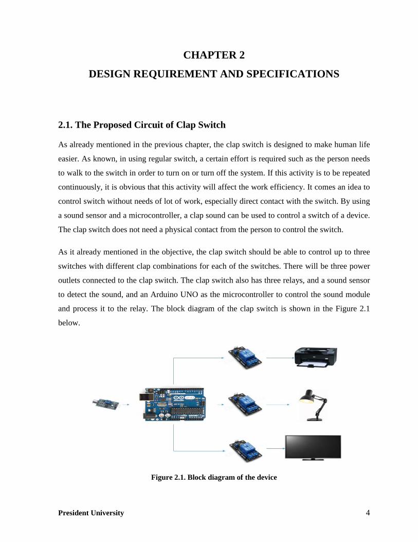
As it already mentioned in the objective, the clap switch should be able to control up to three
switches with different clap combinations for each of the switches. There will be three power
outlets connected to the clap switch. The clap switch also has three relays, and a sound sensor
to detect the sound, and an Arduino UNO as the microcontroller to control the sound module
and process it to the relay. The block diagram of the clap switch is shown in the Figure 2.1
below.
Figure 2.1. Block diagram of the device

President University 5
2.2. Microcontroller
The main component of clap switch is the microcontroller. A microcontroller or an embedded
controller is a system containing I/Os (inputs and outputs), memory, processor, which can be
used to controlling machine. In principle, microcontroller is a small size computer which can
be used to take decision and do repeating commands. It can also be connected to external
devices, such as sensors or actuators.
Figure 2.2. Components of microcontroller [2]
Figure 2.2, shows a microcontroller which contains a lot of components and they will be
described one by one in this subchapter.
• Microprocessor
Microprocessor is a CPU (Central Processing Unit) of a computer, realized on a chip [1]. A
microprocessor has inputs and outputs. The inputs and outputs of a microprocessor are a series
of voltages used to control external devices. Inside of microprocessor it has Control Unit and
ALU (Arithmetic Logic Unit). The principle of microprocessor can be seen in the Figure 2.3
[1].

President University 6
Figure 2.3. Principle design of microprocessor [1]
• Digital I/O
Digital I/O is the main features in the microcontrollers. All microcontrollers have at least 1-2
I/O port. The value of digital I/O in a microcontroller are logical 0 (LOW) and logical 1
(HIGH).
• Analog I/O
The function of analog I/O is similar with the digital I/O. The only difference is in the value.
The value of analog is not only 0 and 1 but the value can be 2.5, 3.3, etc. Most
microcontrollers have integrated analog/digital converters.
• Timer/Counter
Timer and counter is an important part of every microcontroller and most of the controllers
provide more than one timers with 8 and 16 bit resolution [3]. Each timer basically is a counter
which is incremented or decremented upon every clock tick.
• Memory
Memory is part of the microcontroller used for data storage. There are several types of
memory within the microcontroller, which can be seen in Table 2.1.

President University 7
Table 2.1. Types of Memory in Microcontroller
Type Description
ROM (Read Only Memory) It is used to permanently save program being
executed
Masked ROM
This ROM are reserved for the great
manufacturers, the program is loaded into the
chip by the manufacturer
OTP ROM (One Time Programmable
ROM)
This ROM can download program but only
once
UV EPROM (UV Erasable
Programmable ROM)
The memory of this ROM can be erased by
UV lamp and it can write a new program
Flash Memory
The contents of this memory can be written
and cleared unlimited number of times. Ideal
for learning
RAM (Random Access Memory)
It is used for temporary storing data and
intermediate results created and used during
the operation of microcontroller
EEPROM (Electrically Erasable
Programmable ROM)
During operation the contents of this memory
may be changed and during off condition the
memory permanently saved
• Interrupt
Interrupt are useful to make the microcontroller react in some events. Such as when the reset
button in the microcontroller is pressed, then the running program will be stopped and return
to the start of the program.
2.2.1. Arduino UNO
In this final project, the microcontroller that used is Arduino UNO R3 microcontroller. The
reason of choosing Arduino UNO as the microcontroller is because Arduino UNO has enough
pins for this project. Besides, finding Arduino UNO in market is easier than any other Arduino
President University 8
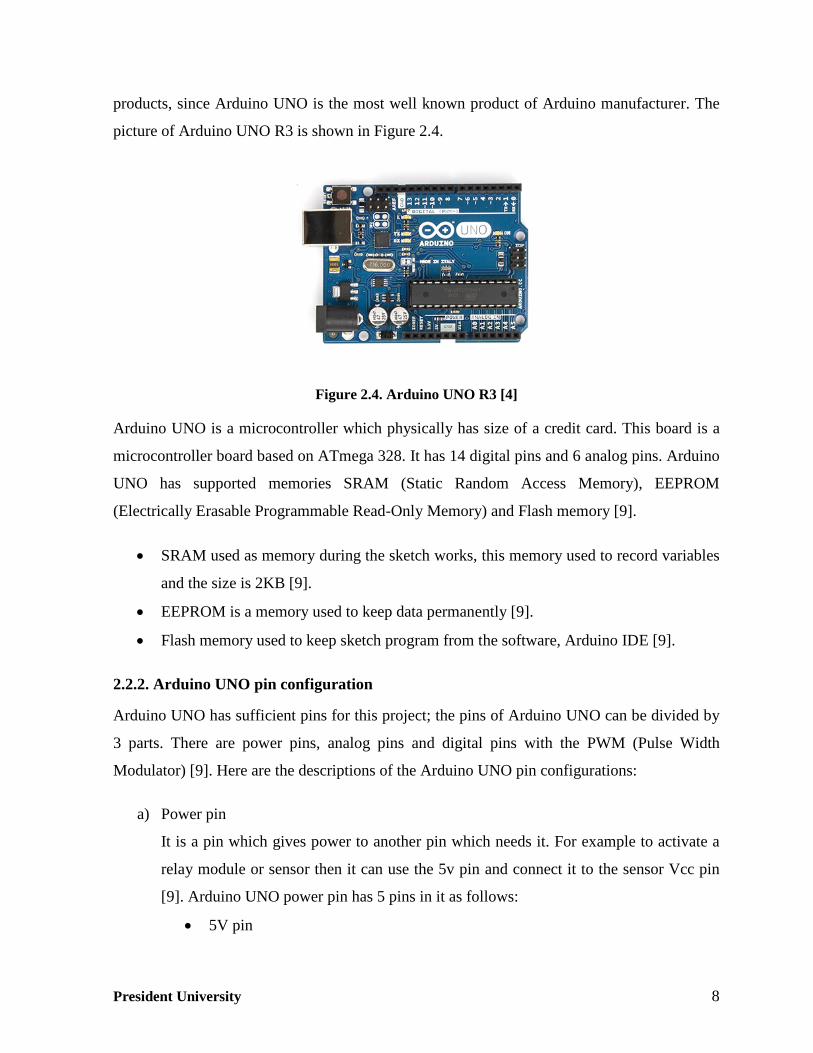
products, since Arduino UNO is the most well known product of Arduino manufacturer. The
picture of Arduino UNO R3 is shown in Figure 2.4.
Figure 2.4. Arduino UNO R3 [4]
Arduino UNO is a microcontroller which physically has size of a credit card. This board is a
microcontroller board based on ATmega 328. It has 14 digital pins and 6 analog pins. Arduino
UNO has supported memories SRAM (Static Random Access Memory), EEPROM
(Electrically Erasable Programmable Read-Only Memory) and Flash memory [9].
• SRAM used as memory during the sketch works, this memory used to record variables
and the size is 2KB [9].
• EEPROM is a memory used to keep data permanently [9].
• Flash memory used to keep sketch program from the software, Arduino IDE [9].
2.2.2. Arduino UNO pin configuration
Arduino UNO has sufficient pins for this project; the pins of Arduino UNO can be divided by
3 parts. There are power pins, analog pins and digital pins with the PWM (Pulse Width
Modulator) [9]. Here are the descriptions of the Arduino UNO pin configurations:
a) Power pin
It is a pin which gives power to another pin which needs it. For example to activate a
relay module or sensor then it can use the 5v pin and connect it to the sensor Vcc pin
[9]. Arduino UNO power pin has 5 pins in it as follows:
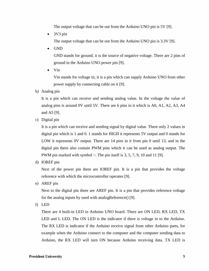
• 5V pin
President University 9
The output voltage that can be out from the Arduino UNO pin is 5V [9].
• 3V3 pin
The output voltage that can be out from the Arduino UNO pin is 3.3V [9].
• GND
GND stands for ground; it is the source of negative voltage. There are 2 pins of
ground in the Arduino UNO power pin [9].
• Vin
Vin stands for voltage in; it is a pin which can supply Arduino UNO from other
power supply by connecting cable on it [9].
b) Analog pin
It is a pin which can receive and sending analog value. In the voltage the value of
analog pins is around 0V until 5V. There are 6 pins in it which is A0, A1, A2, A3, A4
and A5 [9].
c) Digital pin
It is a pin which can receive and sending signal by digital value. There only 2 values in
digital pin which is 1 and 0. 1 stands for HIGH it represents 5V output and 0 stands for
LOW it represents 0V output. There are 14 pins in it from pin 0 until 13, and in the
digital pin there also contain PWM pins which it can be used as analog output. The
PWM pin marked with symbol ~. The pin itself is 3, 5, 7, 9, 10 and 11 [9].
d) IOREF pin
Next of the power pin there are IOREF pin. It is a pin that provides the voltage
reference with which the microcontroller operates [9].
e) AREF pin
Next to the digital pin there are AREF pin. It is a pin that provides reference voltage
for the analog inputs by used with analogReference() [9].
f) LED
There are 4 built-in LED in Arduino UNO board. There are ON LED, RX LED, TX
LED and L LED. The ON LED is the indicator if there is voltage in to the Arduino.
The RX LED is indicator if the Arduino receive signal from other Arduino parts, for
example when the Arduino connect to the computer and the computer sending data to
Arduino, the RX LED will turn ON because Arduino receiving data. TX LED is

President University 10
indicator if the Arduino transmit signal to the computer, for example when using Serial
Monitor command in Arduino IDE, the TX LED will turn ON because Arduino is
transmitting data. L LED is a built-in LED which connected to the pin 13 [9].
g) Reset button
This button used to reset the program that working in the Arduino and makes it start
again from the beginning [9].
h) RX and TX pin
RX pin is in the 0, the pin itself means receive TTL serial data. TX pin is in the 1, the
pin itself means transfer TTL serial data. The picture of Arduino UNO pin
configuration is shown in Figure 2.5 to make it easier understanding it [9].
Figure 2.5. Arduino UNO pin configurations
2.2.3. Arduino IDE
The software that the author used for this final project is Arduino IDE (Integrated
Development Environment) 1.0.5. The interface of Arduino IDE can be seen in the Figure 2.6.

President University 11
Figure 2.6. Arduino IDE 1.0.5 software
Arduino IDE is easy-to-use software since the program language is C-language. It can be used
to make the programming of the code and also uploading the code to the device. The
interesting part is, this software can be used not only to Arduino UNO board programming,
but also to program all of the Arduino Board products. Choosing the type of the board is done
just by clicking the tools menu and there will be board option which shows all of the Arduino
Board products.
2.3. Sound Sensor
Sound Sensor is a sensor that can be used to detect sound. When the sensor detects sound the
sensor will produce a voltage 5 V and transfer it to the microcontroller. Furthermore the
microcontroller will process the input from the sensor. The sensor used in this final project is

President University 12
Sound Sensor FC-04. It has an electret microphone, LM 393, and 3 pins; Vcc, GND and OUT.
The picture of sound sensor FC-04 is shown in Figure 2.7.
The electret microphone is a type of electrostatic capacitor-based microphone; it has FET
transistor inside which the source pin as ground, gate pin connected to the microphone plate,
and drain pin as signal out. The unit of the sensor sensitivity is dBm, since dBm is stands for
an absolute power level and it is in reference to another unit of power in milliwatt. The IC
LM393 function is as the voltage comparing. It compares reference voltage set by the
potentiometer in the sensor with the analog output value. If the analog output values reach
over the reference voltage, the LM393 will send a digital value to indicate the sensor is
triggered [5].
Figure 2.7. Sound Sensor FC-04 [5]
2.3.1. Electret Microphone
The main component in the sound sensor is electret microphone. The function of the electret
microphone is to capture sound wave and translate it into electrical waves. Inside of the
electret microphone there are 2 conducting plates; one is fixed while the other one is a
vibrating diaphragm. The diaphragm is the conducting plate that receives the sound waves and
it causes the change in the capacitance. This change in capacitance produces variance in
voltage on the back plate and sends the electric signals to the output. The figure of the electret
microphone is shown in Figure 2.8 and the specification of the electret microphone is shown
in Table 2.2.
Figure 2.8. Electret Microphone [10]
President University 13
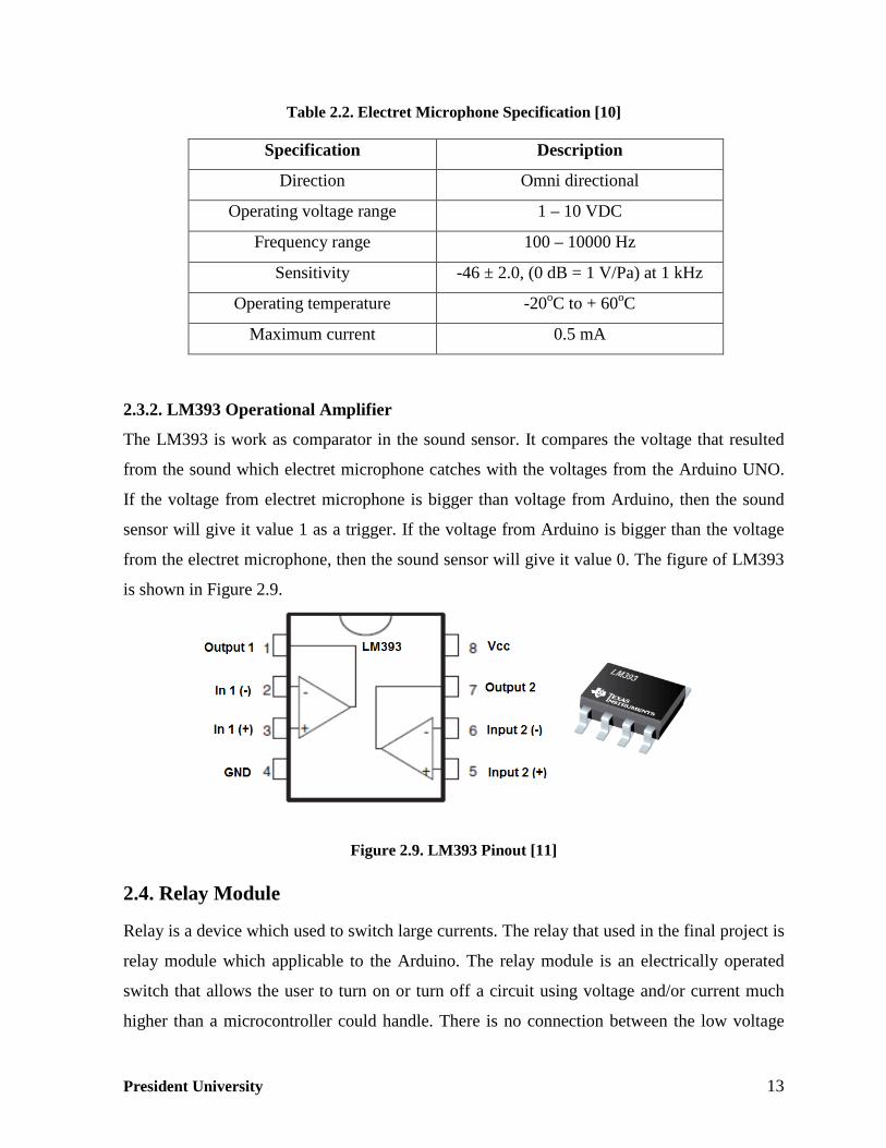
Table 2.2. Electret Microphone Specification [10]
Specification Description
Direction Omni directional
Operating voltage range 1 – 10 VDC
Frequency range 100 – 10000 Hz
Sensitivity -46 ± 2.0, (0 dB = 1 V/Pa) at 1 kHz
Operating temperature -20oC to + 60oC
Maximum current 0.5 mA
2.3.2. LM393 Operational Amplifier
The LM393 is work as comparator in the sound sensor. It compares the voltage that resulted
from the sound which electret microphone catches with the voltages from the Arduino UNO.
If the voltage from electret microphone is bigger than voltage from Arduino, then the sound
sensor will give it value 1 as a trigger. If the voltage from Arduino is bigger than the voltage
from the electret microphone, then the sound sensor will give it value 0. The figure of LM393
is shown in Figure 2.9.
Figure 2.9. LM393 Pinout [11]
2.4. Relay Module
Relay is a device which used to switch large currents. The relay that used in the final project is
relay module which applicable to the Arduino. The relay module is an electrically operated
switch that allows the user to turn on or turn off a circuit using voltage and/or current much
higher than a microcontroller could handle. There is no connection between the low voltage
President University 14
circuit operated by the microcontroller and the high power circuit [6]. The general
specification of the relay module is shown in Table 2.3.
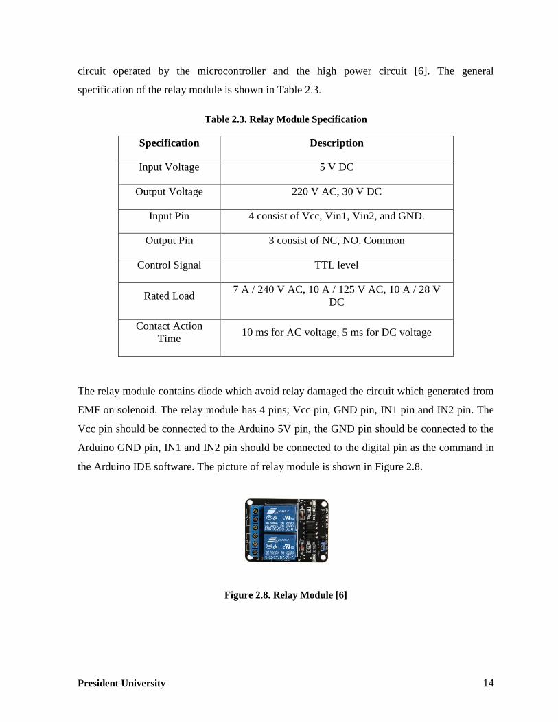
Table 2.3. Relay Module Specification
Specification Description
Input Voltage 5 V DC
Output Voltage 220 V AC, 30 V DC
Input Pin 4 consist of Vcc, Vin1, Vin2, and GND.
Output Pin 3 consist of NC, NO, Common
Control Signal TTL level
Rated Load 7 A / 240 V AC, 10 A / 125 V AC, 10 A / 28 V DC
Contact Action Time 10 ms for AC voltage, 5 ms for DC voltage
The relay module contains diode which avoid relay damaged the circuit which generated from
EMF on solenoid. The relay module has 4 pins; Vcc pin, GND pin, IN1 pin and IN2 pin. The
Vcc pin should be connected to the Arduino 5V pin, the GND pin should be connected to the
Arduino GND pin, IN1 and IN2 pin should be connected to the digital pin as the command in
the Arduino IDE software. The picture of relay module is shown in Figure 2.8.
Figure 2.8. Relay Module [6]

President University 15
2.5. AC/DC Adaptor
The adaptor used in the final project is AC/DC adaptor as the external power supply for the
Arduino UNO. It contains a transformer to convert AC voltage 220 V becomes DC voltage
12 V with current flow 2 A. The picture of the AC/DC Adaptor is shown in Figure 2.9.
Figure 2.9. AC/DC Adaptor
2.6. Power Outlet
Power outlet is plug-in equipment that is used to connect electronic appliances to the power
supply (PLN voltage supply). The power outlet used in the final project is from the brand
Broco. The power outlet can be used for pronge plug that are positive voltage and negative
voltage, or pronge plug added with a ground cable for safety. The picture of the power outlet
is shown in Figure 2.10.
Figure 2.10. Broco Power Outlet

President University 16
CHAPTER 3
DESIGN DEVELOPMENT AND IMPLEMENTATION
3.1. Introduction to the Design Development and Implementation
The purpose of this final project is to make an easy-to-use home automation device. In this
chapter, the hardware and the software development of the clap switch are described. Firstly,
this chapter begins with the explanation about general work procedures of the device by using
block diagram, then explanation of the overall system that works in the device is presented by
using flow chart, the list of components required for the device, hardware design, and the
prototype of the device are explained by figure in breadboard, continue with the
implementation of Arduino UNO in the device and the last is software implementation by
using Arduino IDE program.
To make it easier to understand, the author explains this chapter according to the flows of the
V-model sketched in Figure 3.1 below.
Figure 3.1. V-model [7]

President University 17
The block diagram of the clap switch is shown on Figure 3.2 in the next page.
Figure 3.2. Block diagram of the device
The clap switch reacts to 3 kinds of claps. The first power outlet will react when the sound
sensor is triggered by the sound of 2 claps. The second power outlet will react when the sound
sensor is triggered by the sound of 3 claps. The third power outlet will react when the sound
sensor is triggered by the sound of 4 claps. All of the power outlets have the same time limit to
hear the claps sound, which is 800 milliseconds. When it reaches to the time limit, the power
outlet which has been triggered by the clap sound will react and allow the power flows to the
electronic appliance connected to the power outlet. The Figure 3.3 shows the overall system
which works on the clap switch.

President University 18
StartStart
Hear the clap sound for 800ms
Is the clap = 2?
Switch 1 triggered
Is the clap = 3?
Is the clap = 4?
Switch 2 triggered
Switch 3 triggered
Switch 1 condition
OFF?
Switch 2 condition
OFF?
Switch 3 condition
OFF?
Switch 1 turn ON
Switch 1 turn OFF
Switch 2 turn ON
Switch 2 turn OFF
Switch 3 turn ON
Switch 3 turn OFF
YES NO
YES YES YESNO NO NO
NO
NO
YES
YES
Repeat the process
End
Device plugged in to the power
supply
Device plugged out from the power
supply
Figure 3.3. Flow chart of clap switch
3.2. Hardware Implementation
This part explains how the clap switch prototype is built. The explanation will be presented by
using pictures and wiring diagrams. The components required in the hardware development of
the clap switch are:
• 1 Wood box as the casing of the clap switch.
• 1 Arduino UNO as the microcontroller of the device.
• 1 Sound Sensor FC-04 as the input of a signal to the microcontroller
• 1 Matrix board to spread the Vcc and GND value from arduino to other components.

President University 19
• 3 relay module as a switch that control the voltage 220 V flows to the electronic
appliances.
• 4 power outlet; 3 power outlets used in the front of the box and 1 of the power outlet is
used in the inside of the device for the adaptor.
• 1 ADC Adaptor 12v as a power supply for the Arduino.
• 20 Cable jumpers to connect the pin from sensor relay and LED to the Arduino.
• 3 Red LEDs as indicator of the power outlet.
3.2.1. Hardware Design
The case of device is made of wood. It has a cuboid shape. From the Figure 3.4, it can be seen
that the device has 3 power outlets and 1 electret microphone as the sound sensor. The electret
microphone is putted outside of the case, so it will be able to hear the sound more accurate and
precise. The LEDs putted at the top of the power outlet as the indicator of which power outlet
is in ON condition and which power outlet is in OFF condition.
Figure 3.4. Clap switch design

President University 20
3.2.2. Arduino UNO Implementation
Arduino UNO is the brain of the clap switch circuit. The microcontroller processes the input
detected by the sound sensor controls the relay to do the output. The power to the Arduino
UNO is provided by ADC adaptor. It has an output 12 V and 2 A.
Figure 3.5 shows the other components powered from the Vcc pin and GND pin of Arduino
UNO. The figure represents the test bench of this final project. It has no relay yet, it only use
LED as indicator. If there are trigger of a clap sound, then the LED in the switch will be
turned on. For example, if there are 2 claps then the LED in switch 1 will turn on.
Figure 3.5. Clap switch prototype
As seen in Figure 3.6, most of the components are powered through the Arduino UNO. The
power supply from the adaptor is connected to the DC jack of the Arduino UNO. The inputs
and outputs of other components are connected to the digital pins of the Arduino UNO. The
complete pin configuration is shown in Table 3.1.

President University 21
Figure 3.6. Hardware pin connections
Table 3.1. Hardware Pin Configurations
Pin Number Function
Digital pin 12 Input pin for sound sensor
FC -04
Digital pin 2 Output pin relay switch 1
Digital pin 4 Output pin relay switch 2
Digital pin 7 Output pin relay switch 3
Digital pin 8 Output led 1
Digital pin 9 Output led 2
Digital pin 10 Output led 3
3.3. Software Implementation
To implement the program to the microcontroller, the author used Arduino IDE 1.0.5. There
are two main functions which must be mentioned in the Arduino IDE programming. The first
function is setup(), which runs only once at the beginning. The second function is loop(),
which will run continuously in a loop until the power to the Arduino is off. The code of the

President University 22
clap switch circuit is explained on Table 3.2 and the complete lines of the program can be
found on Appendix.
Table 3.2. Programming Explanation
The Code Description
int soundSensor = 12;
int relay1 = 2;
int relay2 = 4;
int relay3 = 7;
int led1 = 8;
int led2 = 9;
int led3 = 10;
int claps = 0;
long detectionSpanInitial = 0;
long detectionSpan = 0;
boolean lightState = false;
boolean ledState = false;
boolean lampState = false;
void setup() {
pinMode(soundSensor, INPUT);
pinMode(relay1, OUTPUT);
pinMode(relay2, OUTPUT);
pinMode(relay3, OUTPUT);
pinMode(led1, OUTPUT);
pinMode(led2, OUTPUT);
pinMode(led3, OUTPUT);
Serial.begin(9600);
}
// it explains the pin placement of components
such as sound sensor in pin number 12. Relay
in pin number 2, 4 and 7. LED in pin number
8, 9 and 10
// It is explain the value of variable “claps”
// It is explain the value of variable
“detectionSpanInitial” and “detectionSpan”
// Boolean means the variable only holds one
of two values which are true or false.
// setup() is a function which runs only once
at the beginning.
// pinMode() command it configures the pin
inside the bracket to behave either as an input
or output, according the programmer needs.
// It is to display an information in the Serial
Monitor in Arduino IDE. The number 9600 in
the program is stand for 9600 baud rate. If 1

President University 23
void loop() {
int sensorState = digitalRead(soundSensor);
if (sensorState == 0)
{
if (claps == 0)
{
detectionSpanInitial = detectionSpan =
millis();
claps++;
}
else if (claps > 0 && millis()-detectionSpan
>= 50)
{
detectionSpan = millis();
claps++;
}
}
if (millis()-detectionSpanInitial >= 800)
{
if (claps == 4)
symbol is equivaled to 5 bits, then 9600
baud/s is equal to 48000 bits/s.
// loop() is a function which always running
repeatedly until there is no power flows in
arduino
// Declare the value of sensorState based on
the reading result of the sensor
// it means if the value of variable sensorState
is equal to zero and if the claps value is equal
to the zero, then the value of
detectionSpanInitial is the same with
detectionSpan and also the same with
millis().When the value of variable
detectionSpanInitial is the same with
detectionSpan and also the same with millis()
then claps++, it means the value of the clap
will increase by one and returns the old value
of the clap
// else if() it means if the value of the claps is
more than zero and the time is more than 50
milliseconds then the value of the
detectionSpan is the same with the value of
millis(), the claps value will increase by one
and returns to the old value of claps
// if the time to hear the sound is more than
800 milliseconds and there are 4 claps then
when the lampState in off state, it will change

President University 24
{
if (!lampState)
{
lampState = true;
Serial.println("Power outlet 3 OFF");
delay(500);
digitalWrite(relay3, HIGH);
digitalWrite(led3, HIGH);
}
else if (lampState)
{
lampState = false;
Serial.println("Power outlet 3 ON");
delay(500);
digitalWrite(relay3, LOW);
digitalWrite(led3, LOW);
}
}
if (claps == 3)
{
if (!ledState)
{
ledState = true;
Serial.println("Power outlet 2 OFF ");
delay(500);
digitalWrite(relay2, HIGH);
digitalWrite(led2, HIGH);
}
else if (ledState)
{
ledState = false;
the relay to ON condition and the Serial
Monitor in arduino will show " Power outlet 3
OFF "
// if the 4 claps is triggered and the lampState
in on state, it will change the relay to OFF
condition and the Serial Monitor in arduino
will show “Power outlet 3 ON”
// if the time to hear the sound is more than
800 milliseconds and there are 3 claps then
when the ledState in off state, it will change
the relay to ON condition and the Serial
Monitor in arduino will show " Power outlet 2
OFF "
// if the 3 claps is triggered and the ledState in

President University 25
Serial.println("Power outlet 2 ON ");
delay(500);
digitalWrite(relay2, LOW);
digitalWrite(led2, LOW);
}
}
if (claps == 2)
{
if (!lightState)
{
lightState = true;
Serial.println("Power outlet 1 OFF ");
delay(500);
digitalWrite(relay1, HIGH);
digitalWrite(led1, HIGH);
}
else if (lightState)
{
lightState = false;
Serial.println("Power outlet 1 ON ");
delay(500);
digitalWrite(relay1, LOW);
digitalWrite(led1, LOW);
}
}
claps = 0;
}
}
on state, it will change the relay to OFF
condition and the Serial Monitor in arduino
will show “Power outlet 2 ON”
// if the time to hear the sound is more than
800 milliseconds and there are 2 claps then
when the lightState in off state, it will change
the relay to ON condition and the Serial
Monitor in arduino will show " Power outlet 1
OFF "
// if the 2 claps is triggered and the lightState
in on state, it will change the relay to OFF
condition and the Serial Monitor in arduino
will show “Power outlet 1 ON”
// return the value of claps to zero.

President University 26
CHAPTER 4
RESULTS AND DISCUSSIONS
4.1. Results
The final project device is designed to automatically control the switch of electronic
appliances by a clap sound. The electrets microphone in the device is placed outside of the
casing to let the sensor hear the clap sound more accurately. The device works well in the
room with the size of 3 x 6 meters square. The sensor is very sensitive. It does not only detect
a clap sound but also the sound of finger snap and knocking. The picture of the clap switch
prototype can be seen in Figure 4.1.

President University 27
Figure 4.1. Final project device
Figure 4.2 shows the components inside the device and in the Figure 4.3 it shows the electret
microphone of the sensor, located in the right side of the device.

President University 28
Adaptor 12 V 2 A
Stop contact Stop contact Stop contact
Relay Module
Relay Module
Red LED Red LED Red LED
Arduino UNO
Sound Sensor FC-04
Figure 4.2. Components inside the device
Electret Microphone
Figure 4.3. Electret microphone in the device

President University 29
The function of LED in the upper side of the power outlet is as indicator of the power outlet. If
there is power flows in the power outlet, the LED will turn on and when there is no power
flows in the power outlet, the LED will turn off as indicator that the power outlet is ready to be
triggered with the clap sound. The conditions can be seen in the Figure 4.4.
All stop contacts in OFF condition
All stop contacts in ON condition
Figure 4.4. Conditions of the device
Figure 4.5. Final project device trial with electronic appliances

President University 30
Figure 4.5 shows the initial condition of the final project device when plugged in to the power
supply. The first power outlet of the device is plugged with white study lamp, the second
power outlet of the device is plugged with yellow study lamp and the third power outlet of the
device is plugged with insect killer. As it explained before, when there are power flows to the
power outlet, the LED in the upper side of the power outlet will be in on condition. All of the
electronic appliances are in off condition when they are connected to the clap switch.
Figure 4.6. Final project device when given input 2 claps
Figure 4.6 shows when a two-clap sound is given to the device, the power outlet 1 of the
device is turns into on state. As it can be seen from the LED in the upper side of the power
outlet 1 is turn on and the white study lamp is also in on condition.
Figure 4.7 shows when a three-clap sound is given to the device, the power outlet 2 of the
device is turns into on state. As it can be seen from the LED in the upper side of the power
outlet 2 is turn on and the yellow study lamp is in on condition.

President University 31
Figure 4.7. Final project device when given input 3 claps
The last is the condition of the third power outlet in the Figure 4.8. When a four-clap sound is
given to the device, the power outlet 3 of the device is turns into on state. As it can be seen
from LED in the upper side of the power outlet 3 is turn on and the light in the insect killer is
on.
Figure 4.8. Final project device when given input 4 claps

President University 32
4.2. Discussions
Overall operation of the clap switch is not yet perfect. It still has many mistakes. The sound
sensor detects not only the clap sound but also the finger snap sound and the knocking sound.
Even the sound of relay switch inside the device is also detected by the sound sensor.
Whenever the sound sensor detect a clap sound, finger snap, and knocking sound the green led
will blinked. Figure 4.9 shows the sound sensor condition between the sensor in the standby
state and the condition when the sound sensor detects sound.
Figure 4.9. Sound sensor works
Nevertheless, the sensor does not take the sound as a command. To overcome this problem,
the author is suggests to put styrofoam inside the device in order to reduce the effects of the
relay sound. Other thing needs to be mentioned is regarding the clap repetition. When the
person tries to inputs to the device such as a clap sound with the repetition of more than 4, the
device will only react to the first 800 milliseconds of the clap sound. For example, the author
claps 6 times in 1 second, the clap switch will only react to the first 800 ms of the claps. The
number of claps is considered to be 4 times. Then the clap switch takes this value as a
command and the switch number 3 will be given the signal to react to it.
The frequency range of a clap sound is could not be measured since every time there is a two
hands clapping, it will produce a random frequency, sometimes the frequency is high and

President University 33
sometimes the frequency is low. According to Fletcher [12], a flat clap produces broad-band
sound that typically extends to about 10 kHz while the spectrum of a domed clap usually has
subsidiary maximum somewhere below 1 kHz and then declines with frequency more rapidly
than does the flat clap. The electret microphone has a frequency range from 100 Hz – 10 kHz
[10]. Therefore, the electret microphone can always capture the frequency of a clapping hand.
4.3. Strengths and Weaknesses
The strengths of the clap switch system proposed in this final project are:
• The clap switch runs smoothly as the program implemented in the microcontroller.
• The sensor is very sensitive to sound. Even when the user is around 2 meter from the
clap switch the sound sensor can still recognize the clap and take it as a command.
The weaknesses of the clap switch system in this final project are:
• The sound sensor cannot differentiate the sound between a clap, a finger snap, knock,
and even the sound of relay switch inside the device.
• The microcontroller is easily to get hot. It is because the adaptor used in this final
project is 12 V and 2 A. If the adaptor output is around 7 V and 1 A, the Arduino will
be better exposed.

President University 34
CHAPTER 5
CONCLUSIONS AND RECOMMENDATIONS
5.1. Conclusions
Based on the experiments and analysis of the “Control of 3-Way Switches Using Clap Sound”,
there are two conclusions that can be presented:
1. The Arduino UNO and the sound sensor FC-04 are successfully implemented to
achieve the objective of this final project. The device can be easily controlled through
variations of clap sound with a time limit of 800ms for every command inputted.
2. The device can control 3 switches by a variable number of claps. The device can work
properly according to the number of claps inputted to the device. For switch 1 the input
is 2 claps, switch 2 the input is 3 claps, and switch 3 the input is 4 claps with a time
limit 800ms.
An additional conclusion can be listed as follows:
1. The detection range of the sensor is around 2 meter. If the device is used in the
minimum noise level, the range can be more than 2 meter.
5.2. Recommendations
Even though the objective of this final project is achieved successfully, the device can be
improved to achieve better performance. Some recommendations for the clap switch prototype
resulted from this final project are:
1. The use of sensor with the highest technology such as EasyVR. This will make the
device perform more accurate in detecting sound and also the sensor can help the
device to differentiate the sound around the device.
2. The casing should be designed properly, for example putting styrofoam in the casing to
silence any noise or claps echo in the casing box.
President University 35
3. The directly implement of the clap switch inside the electronic appliances circuit. For
example a television which has clap switch implemented in the circuit, the user will
not have to press a button in the television, even press a button in the remote control to
turn on television.

President University 36
REFERENCES
[1] Silitonga, Arthur. Class Lecture, Topic: “Microcomputer Interfacing”. First Meeting.
Faculty of Engineering, President University, Jababeka, Indonesia, Jan, 2015.
[2] Iqbal, M. Amer, Teach Yourself PIC Misrocontrollers for Absolute Beginners,
Pakistan: Microtronics Pakistan, 2013.
[3] Gunther Gridling, Bettina Weiss, Introduction of Microcontroller, Austria, Vienna
University of Technology, March 19, 2006.
[4] Arduino. (2015). Arduino – Home. Retrieved 1 22, 2015, from Arduino:
https://www.arduino.cc/en/Main/ArduinoBoardUno
[5] Sound Sensor FC-04, Datasheet, SparkFun.
[6] Realy Module, Datasheet, Songle.
[7] Silitonga, Arthur. Class Lecture, Topic: “Microcomputer Interfacing”. Second
Meeting. Faculty of Engineering, President University, Jababeka, Indonesia, Jan, 2015.
[8] Arduino. (2015). Arduino – Home. Retrieved 1 14, 2015, from Arduino:
https://www.arduino.cc/en/Reference/HomePage
[9] Kadir, Abdul. Buku Pintar Pemrograman Arduino, Yogyakarta: MediaKom Indonesia,
2014.
[10] Electret Microphone, Datasheet, Challenge Electronics.
[11] LM393, Datasheet, ON Semiconductor.
[12] Fletcher, Neville H. Research, Shock Waves and The Sound of a Hand-Clap, Canberra
Australian National University, 2013.

President University 37
APPENDIX
int soundSensor = 12; // pin of sensor sound
int relay1 = 2; // pin1 of relay
int relay2 = 4; // pin2 of relay
int relay3 = 7; // pin3 of relay
int claps = 0; // the number of claps
int led1 = 8;
int led2 = 9;
int led3 = 10;
long detectionSpanInitial = 0; // the initial of detection
long detectionSpan = 0; // how long it will detect
boolean lightState = false;
boolean ledState = false;
boolean lampState = false;
void setup() {
pinMode(soundSensor, INPUT); // input of the sensor
pinMode(relay1, OUTPUT); // output by switch of the relay
pinMode(relay2, OUTPUT); // output by switch of the relay
pinMode(relay3, OUTPUT); // output by switch of the relay
pinMode(led1, OUTPUT); // output by switch of the led
pinMode(led2, OUTPUT); // output by switch of the led
pinMode(led3, OUTPUT); // output by switch of the led
Serial.begin(9600);
}
void loop() {
int sensorState = digitalRead(soundSensor);

President University 38
if (sensorState == 0)
{
if (claps == 0)
{
detectionSpanInitial = detectionSpan = millis();
claps++;
}
else if (claps > 0 && millis()-detectionSpan >= 50) // the sensor will detect sound for every
50ms and repeat
{
detectionSpan = millis();
claps++;
}
}
if (millis()-detectionSpanInitial >= 800) // the sensor will detect sound for every
400ms and always repeat
{
if (claps == 4)
{
if (!lampState)
{
lampState = true;
Serial.println("Power outlet 3 OFF ");
delay(500);
digitalWrite(relay3, HIGH);
digitalWrite(led3, HIGH);
}
else if (lampState)
{
lampState = false;
Serial.println("Power outlet 3 ON ");
President University 39
delay(500);
digitalWrite(relay3, LOW);
digitalWrite(led3, LOW);
}
}
if (claps == 3)
{
if (!ledState)
{
ledState = true;
Serial.println("Power outlet 2 OFF ");
delay(500);
digitalWrite(relay2, HIGH);
digitalWrite(led2, HIGH);
}
else if (ledState)
{
ledState = false;
Serial.println("Power outlet 2 ON ");
delay(500);
digitalWrite(relay2, LOW);
digitalWrite(led2, LOW);
}
}
if (claps == 2)
{
if (!lightState)
{
lightState = true;
President University 40
Serial.println("Power outlet 1 OFF ");
delay(500);
digitalWrite(relay1, HIGH);
digitalWrite(led1, HIGH);
}
else if (lightState)
{
lightState = false;
Serial.println("Power outlet 1 ON ");
delay(500);
digitalWrite(relay1, LOW);
digitalWrite(led1, LOW);
}
}
claps = 0; // reset
}
}


![The Bible Story - mairangichurch.org.nzmairangichurch.org.nz/dox/Unit 9 Lesson 3_toddlers.pdf · [Clap, clap] When God’s people needed help, He sent a judge. [Clap, clap] But God’s](https://static.fdocuments.in/doc/165x107/5bb7b12309d3f2a4338dbb90/the-bible-story-9-lesson-3toddlerspdf-clap-clap-when-gods-people-needed.jpg)


![Gloria [clap clap], Gloria [clap clap], in excelsis Deo ...](https://static.fdocuments.in/doc/165x107/62107ac91ae5b738792e36b6/gloria-clap-clap-gloria-clap-clap-in-excelsis-deo-.jpg)