CONTROL - Efka...CONTROL DA82GA3312 with control panel V810/V820 INSTRUCTION MANUAL No. 402275...
56
CONTROL DA82GA3312 with control panel V810/V820 INSTRUCTION MANUAL No. 402275 English FRANKL & KIRCHNER EFKA OF AMERICA INC. EFKA ELECTRONIC MOTORS GMBH & CO KG SINGAPORE PTE. LTD.
Transcript of CONTROL - Efka...CONTROL DA82GA3312 with control panel V810/V820 INSTRUCTION MANUAL No. 402275...

CONTROL DA82GA3312
with control panel V810/V820
INSTRUCTION MANUAL
No. 402275 English
FRANKL & KIRCHNER EFKA OF AMERICA INC. EFKA ELECTRONIC MOTORS GMBH & CO KG SINGAPORE PTE. LTD.


EFKA DA82GA3312 3 CONTENTS Page
1 Range of Applications 6 1.1 Use in Accordance with Regulations 6 2 Scope of Supply 6 2.1 Special Accessories 7 3 Operation 8 3.1 Access Authorization upon Command Input 8 3.2 V810 Control Panel Operation 9 3.2.1 Code Number Input on the V810 Control Panel 9 3.2.2 Parameter Input at the Operator Level on the V810 Control Panel 9 3.2.3 Parameter Input at the Technician/Supplier Level on the V810 Control Panel 10 3.3 V820 Control Panel Operation 10 3.3.1 Code Number Input on the V820 Control Panel 10 3.3.2 Parameter Input at the Operator Level on the V820 Control Panel 11 3.3.3 Parameter Input at the Technician/Supplier Level on the V820 Control Panel 11 3.4 Program Identification 12 3.5 Direct Input of Maximum Speed Limitation (DED) with Control Panel 12 3.5.1 Setting on the V810 Control Panel 12 3.5.2 Setting on the V820 Control Panel 12 3.6 Keys for Background Information (HIT) with V820 13 3.6.1 Example of HIT 13 3.7 Programming of Seams 15 3.7.1 Programming Mode 16 3.7.2 Seam with Stitch Counting 16 3.7.3 Backward Seam with Stitch Counting 16 3.7.4 Stitch Counting and/or Light Barrier 16 3.7.5 Detailed Example 17 3.7.6 Maximum Number of Seams Exceeded 19 3.7.7 Execution (Pattern) Mode 19 3.7.8 Further Settings for TEACH IN 19 4 Putting into Service 21
5 Setting the Basic Functions 21 5.1 Direction of Motor Rotation 21 5.2 Selection of the Machine Series 21 5.2.1 Emergency Run Function If Machine Select Is Invalid 22 5.3 Positions 22 5.3.1 Setting the Reference Position 22 5.3.2 Setting the Reference Position on Control Panel V810 22 5.3.3 Setting the Reference Position on Control Panel V820 23 5.3.4 Setting the Positions on the V810 Control Panel 23 5.3.5 Setting the Positions on the V820 Control Panel 24 5.4 Positioning Speed 25 5.5 Maximum Speed Compatible with the Sewing Machine 25 5.6 Maximum Speed 25 5.7 Display of the Signal and Stop Positions 25 5.8 Braking Characteristics 26 5.9 Braking Power at Standstill 26 5.10 Starting Characteristics 26 5.11 Actual Speed Display 26

EFKA DA82GA3312 4 CONTENTS Page
6 Functions and Settings 27 6.1 First Stitch after Power On 27 6.2 Softstart 27 6.2.1 Softstart Speed 27 6.2.2 Softstart Stitches 27 6.3 Sewing Foot Lifting 27 6.4 Sewing Foot Pressure Reduction 28 6.5 Start Backtack 29 6.5.1 Speed n3 at the Start of the Seam 29 6.5.2 Start Backtacking Stitch Count 29 6.5.3 Speed Release 30 6.5.4 Double Start Backtack 30 6.5.5 Single Start Backtack 30 6.6 End Backtack 30 6.6.1 Speed n4 at the Seam End 30 6.6.2 End Backtacking Stitch Count 31 6.6.3 Last Stitch Backward 31 6.6.4 Double End Backtack 31 6.6.5 Single End Backtack 31 6.6.6 Backtack Synchronization 31 6.7 Start and End Backtack with Switch-On and Switch-Off Delay 31 6.8 Start Ornamental Backtack 32 6.9 End Ornamental Backtack 32 6.10 Multiple Backtacking 33 6.11 Catch backtacking 33 6.12 Intermediate Backtack 33 6.13 Backtack Suppression/Recall 34 6.14 Holding Power of the Stitch Regulator Solenoid 34 6.15 Reverse Motor Rotation 35 6.16 Machine Run Blockage (Safety Switch) 35 6.16.1 Machine Start Blockage (Blockage 1 and 2) 36 6.16.2 Function “Machine Run Blockage” 1 (Safety Function) Parameter 283 = 1 36 6.16.3 Function “Machine Run Blockage” 2 (Control Function) Parameter 283 = 2 36 6.17 Thread Monitor 37 6.17.1 Input Signals 37 6.17.2 Parameter 195 = 0 – No Thread Monitor Function 37 6.17.3 Parameter 195 = 1 – Model 270 / No Stop / Sewing Foot Down after Seam End 37 6.17.4 Parameter 195 = 2 – Model 767, N291 / With Stop / Sewing Foot Up after Seam End 37 6.17.5 Parameter 195 = 3 – Model 767, N291 / With Stop / Sewing Foot Down after Seam End 38 6.17.6 Parameter 195 = 4 – With Thread Monitor Stitch Counting 38 6.18 Needle Cooling 38 6.19 High Lift for Walking Foot 38 6.19.1 Manual High Lift for Walking Foot – Speed Limitation 39 6.19.2 Maximum High Lift for Walking Foot by Using a Key 39 6.19.3 High Lift for Walking Foot Operational Mode Not Stored (Pa. 138 = OFF, Pa. 184 = 0) 39 6.19.4 High Lift for Walking Foot Operational Mode Stored (Pa. 138 = ON) 39 6.19.5 High Lift for Walking Foot Operational Mode Not Stored with Minimum Number of
Stitches (Pa. 138 = OFF, Pa. 184 = >0) 39 6.20 Speed Limitation 39 6.20.1 Speed Limitation DB2000/DB3000 39 6.20.2 Analog Speed Limitation 40 6.20.3 Analog Speed Limitation Speedomat 40 6.20.4 Jumper S1 41 6.20.5 Setting the Speed Limitation Depending on High Lift with the V820 Control Panel 41 6.20.6 Setting the Speed Limitation Depending on High Lift with the V810 Control Panel 41

EFKA DA82GA3312 5 CONTENTS Page 6.21 Switch Stitch Length 42 6.22 Roller 42 6.23 Thread Clamp 43 6.24 Thread Trimming Operation 44 6.24.1 Thread Trimmer 44 6.24.2 Thread Wiper 44 6.24.3 Thread Tension Release 44 6.24.4 2nd Thread Tension Release (FSPL2) 45 6.24.5 Thread Tension Reduction 45 6.24.6 Coupling Thread Tension Release with the Sewing Foot 45 6.24.7 Coupling Thread Tension Reduction with High Lift for Walking Foot / Speedomat 45 6.25 Seam with Stitch Counting 46 6.25.1 Number of Stitches for a Seam with Stitch Counting 46 6.25.2 Stitch Counting Speed 46 6.26 Free Seam and Seam with Light Barrier 46 6.27 Light Barrier 47 6.27.1 Speed after Light Barrier Sensing 47 6.27.2 General Light Barrier Functions 47 6.27.3 Reflection Light Barrier LSM001A 48 6.27.4 Automatic Start Controlled by Light Barrier 48 6.27.5 Light Barrier Filter for Knitted Fabrics 48 6.28 Needle Up/Down / Single Stitch 48 6.29 F1/F2 Function Key Assignment on the V810/V820 Control Panels 49 6.30 Signal Output Position 2 50 6.31 Signal Output 512 Impulses per Rotation 50 6.32 Actuator 50 6.33 Acoustic Signal 51 6.34 Master Reset 51 7 Input and Output Function Test 52 7.1 Function Test with the V810/V820 Control Panel 52 8 Error Displays 53
9 Operating Elements of the V810 Control Panel 54
10 Operating Elements of the V820 Control Panel 55

EFKA DA82GA3312 6 1 Range of Applications The drive is suitable for lockstitch, machines:
Brand Series
DÜRKOPP ADLER N291, 069, 204, 205, 221, 266, 267, 268, 269, 366, 271, 381, 382, 467, 767, 768, 4180, 4280, 8967
1.1 Use in Accordance with Regulations The drive is not an independently operating machine, but is designed to be incorporated into other machinery. It must not be put into service until the machinery into which it is to be incorporated has been declared in conformity with the provisions of the EC Directive (Appendix II, paragraph B of the Directive 89/392/EEC and supplement 91/368/EEC). The drive has been developed and manufactured in accordance with the relevant EC standards: EN 60204-3-1:1990 Electrical equipment of industrial machines: Particular requirements for industrial sewing machines, sewing units and sewing systems. Operate the drive only on thread processing machines in dry areas
2 Scope of Supply
1 Direct current motor DC1600 1 Electronic control vario dc DA82GA3312 - Power pack N153 (optional N155) - Actuator EB301 (optional EB302, softer spring) 1 Control panel V810 (optional V820) 1 Position transmitter P6-1 1 Power switch NS108 (optional NS108D)
1 Set of standard accessories B131 1 Set of accessories Z57 consisting of: belt guard, complete consisting of: extension cable for EB3.. set of hardware motor mounting foot bracket 1 and 2, short documentation
Note If there is no metallical contact between drive (motor) and machine head, the potential equalization cord supplied
with the unit is to be wired from the machine head to the terminal provided on the control box!
CAUTION When selecting the installation site and the layout of the connecting cable, the safety
instructions must be followed with no exceptions. Particular attention should be paid to maintaining the proper distance from moving
parts!

EFKA DA82GA3312 7 2.1 Special Accessories
Control panel Variocontrol V810 - part no. 5970153 Control panel Variocontrol V820 - part no. 5970154 Reflection light barrier module LSM001A - part no. 6100028 EFKANET interface IF232-2 - part no. 7900068 Actuating solenoid type EM1.. (for e. g. sewing foot lifting, backtacking, etc.) - see specification
“solenoids” for available models
Extension cable for commutation transmitter, approx. 1100 mm long, complete with - part no. 1112247 plug and socket connector Extension cable for position transmitter, approx. 1100 mm long, complete with - part no. 1100409 plug and socket connector Extension cable for motor connection, approx. 1500 mm long - part no. 1111857 Extension cable for external actuator, approx. 750 mm long, complete with - part no. 1111845 plug and socket connector Extension cable for external actuator, approx. 1500 mm long, complete with - part no. 1111787 plug and socket connector 5-pin plug with locking screw for the connection of another external actuator - part no. 0501278 External actuator type EB302 (softer spring) with approx. 250 mm connecting - part no. 4170012 cable and 5-pin plug with locking screw Foot control type FB301 with one pedal for standing operation, with approx. 300 mm - part no. 4170013 connecting cable and plug Foot control type FB302 with three pedals for standing operation, with approx. 1400 mm - part no. 4170018 connecting cable and plug Potential equalization cord 700 mm long, LIY 2.5 mm2, grey, with spades - part no. 1100313 on both sides Pulley 40 mm Ø with special belt intake and slip-off protection (use SPZ belt) - part no. 1112223 Pulley 50 mm Ø with special belt intake and slip-off protection (use SPZ belt) - part no. 1112224 Knee switch type KN3 (pushbutton) with cord of approx. 950 mm length without plug - part no. 5870013 Sewing light transformer - please indicate line
voltage and sewing light voltage (6,3V or 12V)
Pitman rod for foot control - available versions on inquiry
8-pin plug with locking screw MAS 8100S - part no. 0502865 8-pin plug with locking screw MAS 8100SN - part no. 0501279 15-contact SubminD male connector with half-shell housing - part no. 1113193 37-contact SubminD male connector with half-shell housing - part no. 1112900
Note Select the pulley such that the motor runs at approx. 4000 RPM with max. stitch number.

EFKA DA82GA3312 8 3 Operation 3.1 Access Authorization upon Command Input
In order to prevent unintentional changes of preset functions the command input is distributed at various levels. The following persons have access: - the supplier to the highest and all subordinate levels using a code number
- the technician to the next lower and all subordinate levels using a code number
- the operator to the lowest level without using a code number ACaCCallufruf
Call-up Supplier: Code number for the control panel is 3112
Supplier Level 200 series of
parameter numbers
Technician: Code number for the control panel is 1907
Technician Level 100 series of
parameter numbers
Operator Level

EFKA DA82GA3312 9
3.2 V810 Control Panel Operation
3.2.1 Code Number Input on the V810 Control Panel Example: Technician level CODE number selection on the V810 control panel TURN POWER OFF + TURN POWER ON. First digit blinks ! Press the + or – key to select the first digit ! Press the >> key ! Second digit blinks ! Press the + or – key to select the second digit ! Press the >> key twice ! Fourth digit blinks ! Press the + or – key to select the fourth digit! If the CODE number is correct, the first PARAMETER number at the selected level is displayed !
3.2.2 Parameter Input at the Operator Level on the V810 Control Panel Example: CODE number has not been input ! TURN POWER ON ! First parameter at the operator level is displayed. Second parameter at the operator level is displayed. The next or previous parameter can be called by pressing the +/- keys. Parameter value is displayed ! Change parameter value by pressing the +/- keys. Parameter value is entered. Display advances to the next parameter. Press the + key several times until the desired parameter is displayed ! Parameter value is displayed !
Technician Level Code Number => 1907 and Supplier Level Code Number => 3112
P C – 0 0 0 0
+ - C – 1 0 0 0
» C – 1 0 0 0
+ - C – 1 9 0 0
» » C – 1 9 0 0
+ - C – 1 9 0 7
E F – 1 0 0
d A 8 2 G A
P F – 0 0 0
+ F – 0 0 1
E 0 0 3
+ X X X
E F – 0 0 2
+ F – 0 0 9
E O F F

EFKA DA82GA3312 10 New parameter value is displayed ! Next parameter is displayed ! or Exit programming ! These values are saved when you start sewing. They remain in effect even after turning the machine off!
3.2.3 Parameter Input at the Technician/Supplier Level on the V810 Control Panel Example: After CODE number input at the technician level. After CODE number input, the first PARAMETER number is displayed! Press the + key ! The next parameter number is displayed ! Press key E! The parameter value is displayed ! Change the parameter value ! Parameter value is entered. Display advances to the next parameter. or Parameter value is entered. The actual PARAMETER number is displayed! or Press key P twice ! Exit programming ! These values are saved when you start sewing. They remain in effect even after turning the machine off!
3.3 V820 Control Panel Operation
3.3.1 Code Number Input on the V820 Control Panel Example: Technician level CODE number selection on the V820 control panel TURN POWER OFF ! + TURN POWER ON ! Input CODE number !
+ O N
Note! The parameter number can also be selected directly, like the code number!
F – 1 0 0
+ F – 1 1 0
E 0 1 8 0
+ - 0 X X X
E F – 0 1 0
P d A 8 2 G A
E F – 1 1 1
P F - 1 1 0
P P d A 8 2 G A
Technician Level Code Number => 1907 and Supplier Level Code Number => 3112
P C–0000
1 9 C–1907 0 7
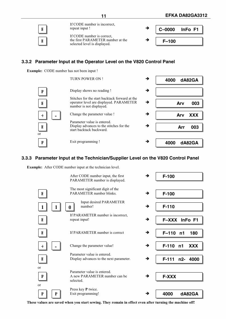
EFKA DA82GA3312 11 If CODE number is incorrect, repeat input ! If CODE number is correct, the first PARAMETER number at the selected level is displayed.
3.3.2 Parameter Input at the Operator Level on the V820 Control Panel Example: CODE number has not been input ! TURN POWER ON ! Display shows no reading ! Stitches for the start backtack forward at the operator level are displayed. PARAMETER number is not displayed. Change the parameter value ! Parameter value is entered. Display advances to the stitches for the start backtack backward. or Exit programming !
3.3.3 Parameter Input at the Technician/Supplier Level on the V820 Control Panel Example: After CODE number input at the technician level. After CODE number input, the first PARAMETER number is displayed. The most significant digit of the PARAMETER number blinks. Input desired PARAMETER number! If PARAMETER number is incorrect, repeat input! If PARAMETER number is correct Change the parameter value! Parameter value is entered. Display advances to the next parameter. or Parameter value is entered. A new PARAMETER number can be selected. or Press key P twice. Exit programming! These values are saved when you start sewing. They remain in effect even after turning the machine off!
E C–0000 InFo F1
E F–100
4000 dA82GA
E Arv 003
E Arr 003
P 4000 dA82GA
P
+ - Arv XXX
F-100
E F-100
1 1 F-110 0
E F–XXX InFo F1
E F–110 n1 180
E F-111 n2- 4000
P F-XXX
+ - F-110 n1 XXX
P P 4000 dA82GA
EFKA DA82GA3312 12
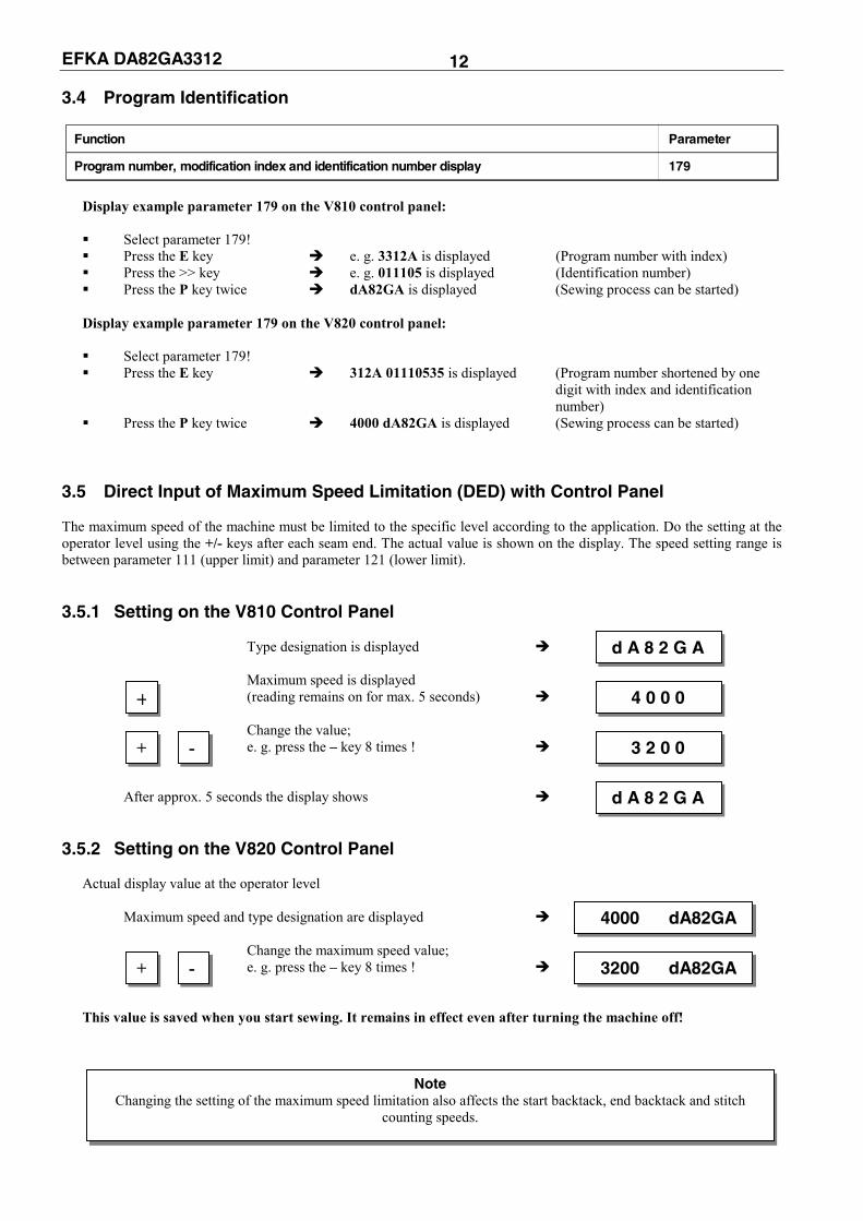
3.4 Program Identification
Function Parameter
Program number, modification index and identification number display 179
Display example parameter 179 on the V810 control panel: Select parameter 179! Press the E key e. g. 3312A is displayed (Program number with index) Press the >> key e. g. 011105 is displayed (Identification number) Press the P key twice dA82GA is displayed (Sewing process can be started)
Display example parameter 179 on the V820 control panel: Select parameter 179! Press the E key 312A 01110535 is displayed (Program number shortened by one
digit with index and identification number)
Press the P key twice 4000 dA82GA is displayed (Sewing process can be started)
3.5 Direct Input of Maximum Speed Limitation (DED) with Control Panel The maximum speed of the machine must be limited to the specific level according to the application. Do the setting at the operator level using the +/- keys after each seam end. The actual value is shown on the display. The speed setting range is between parameter 111 (upper limit) and parameter 121 (lower limit). 3.5.1 Setting on the V810 Control Panel
Type designation is displayed Maximum speed is displayed (reading remains on for max. 5 seconds) Change the value; e. g. press the – key 8 times ! After approx. 5 seconds the display shows
3.5.2 Setting on the V820 Control Panel Actual display value at the operator level Maximum speed and type designation are displayed Change the maximum speed value; e. g. press the – key 8 times ! This value is saved when you start sewing. It remains in effect even after turning the machine off!
d A 8 2 G A
+ 4 0 0 0
+ - 3 2 0 0
d A 8 2 G A
4000 dA82GA
+ - 3200 dA82GA
Note Changing the setting of the maximum speed limitation also affects the start backtack, end backtack and stitch
counting speeds.

EFKA DA82GA3312 13
3.6 Keys for Background Information (HIT) with V820 (key assignment see figure on the last page) For fast operator information, the values of functions enabled using key 1, 2, 3, 4 or 9 are displayed on the control panel for approx. 3 seconds. During this time, the respective values can be varied directly by pressing the + or - key. 3.6.1 Example of HIT
Increase stitch-count seam section from 20 stitches to 25 stitches. Stitch-count function (key 2) is off.
Display after power on ↓↓↓↓ Press key 2 briefly ! Lefthand arrow and stitch-count function are on Press the + key ! Increase the number of stitches from 20 to 25 ! Display after approx. 3 seconds
Stitch-count function (key 2) is already On. Display after power on ↓↓↓↓ Press key 2 for at least 1 second! Lefthand arrow goes off momentarily; stitch-count function is on Press the + key ! Increase the number of stitches from 20 to 25 ! Display after approx. 3 seconds This value is saved when you start sewing. It remains in effect even after turning the machine off!
Function key F Various parameters, even higher-level parameters, can be enabled or disabled by pressing the function key (key 9). The following functions may be assigned to the function key: 1 Softstart ON/OFF 2 Ornamental backtack ON/OFF 3 High lift for walking foot operational mode stored = ON / operational mode not stored = OFF 4 Needle cooling ON/OFF 5 Reverse motor rotation ON/OFF The key assignment can be changed as follows:
Display after power On Press key P!
Note The following functions are possible only with the V820 control panel!
4000 dA82GA
2 Stc 020
+ Stc 025
4000 dA82GA
2 Stc 020
+ Stc 025
4000 dA82GA
4000 dA82GA
P
4000 dA82GA

EFKA DA82GA3312 14 Press key E ! Press key E several times until the letter symbol –F– appears ! (ornamental backtack On/Off) Press the – key! (softstart On/Off) Press key P! The assignment is completed.
The number of softstart stitches can be changed as follows:
Example: change number of stitches from 1 to 3 (softstart function (key 9) is off). Press key 9 briefly ! The arrow above the key lights up (softstart function is On) Press the + key ! Number of stitches increases. Display after 3 seconds
Example: change number of stitches from 1 to 3 (softstart function (key 9) is already on). Press key 9 for at least 1 sec. ! The arrow above the key goes off momentarily (softstart function is On) Press the + key ! Number of stitches increases. Display after 3 seconds
This value is saved when you start sewing. It remains in effect even after turning the machine off!
E c2 002
E -F- 2
- -F- 1
P 4000 dA82GA
9 SSc 001
+ SSc 003
4000 dA82GA
9 SSc 001
+ SSc 003
4000 dA82GA

EFKA DA82GA3312 15 3.7 Programming of Seams Um häufig vorkommende Nähabläufe komfortabel einstellen und abrufen bzw. verschiedene Nähte mit unterschiedlichen Einstellungen aneinanderreihen zu können, ist die Naht-Programmierung möglich.
A maximum of 8 patterns with a total of 40 seams can be established. Programming is possible only if a code number has not been input after powering on! The functions “start backtack”, “end backtack”, “stitch counting”, “thread trimming” and “sewing foot lift” can
be assigned individually to each seam. For all 8 patterns, different numbers of start and end backtacking stitches can be programmed. The maximum number of stitches for the forward or backward section is limited to 15 stitches. It is possible to “teach in” seams with stitch counting by executing the desired sections.
Example 1: Pattern 1 40 seams Example 3: Pattern 1 10 seams Pattern 2-8 0 seams Pattern 2 15 seams Example 2: Pattern 1 4 seams Pattern 3-8 0 seams Pattern 2 5 seams Pattern 3 6 seams Pattern 4 25 seams Pattern 5-8 0 seams Examples 1 and 2 show that optimal utilization of the storage capacity is possible.
Functions of programming of seams:
21
1 2
11
5
5
3 4
43
7
7
6
6
1 3 1 41 2 1 61 5
0
1 0
8 9
98
R F
BA
1 91 81 7
EP
+ -
1
KL2517
Function Arrow Function Arrow 1 Single start backtack On left 7 Basic position down left Double start backtack On right Basic position up right Start backtack Off --- 8 No function ---
2 Counted seam forward On left 9 Switching from one pattern or seam to the next according to the setting of parameter 277
Counted seam backward On right 10 Memory for programming of seams On left Counted seam Off --- Memory for programming of seams Off ---
3 Light barrier uncovered/covered On left 11 Program symbol Light barrier covered/uncovered On right 12 Display of program number Light barrier Off --- 13 Seam symbol
4 Single end backtack On left 14 Display of seam number Double end backtack On right 15 Symbol of number of stitches of a seam End backtack Off --- 16 Display of number of stitches
5 Thread trimmer On left 17 Light barrier symbol Thread wiper On right 18 Display of light barrier compensating stitches Thread trimmer and thread wiper On both 19 Programming mode On blinking Thread trimmer and thread wiper Off --- Execution (pattern) mode On constant
6 Sewing foot in the seam On left A No function during programming Sewing foot after seam end On right B No function during programming Sewing foot in the seam and after seam end On both Sewing foot Off ---

EFKA DA82GA3312 16
3.7.1 Programming Mode Each seam pattern is programmed and stored separately. Exit the teach-in mode after pattern input. The values are saved when you start sewing.
Display configuration: 3 Program number (1...8) 04 Seam number (0...40) 020 Stitches for a seam with stitch counting (0...254) 008 Stitches after light barrier sensing (0...254) Programming: After power On without code number input ! 1 LC display is cleared Display of a parameter 2 at the operator level Lefthand arrow above key 0 blinks. 3 Entry into pattern and seam programming. 4 Changing the pattern number The seam functions (e.g. sewing foot lift, start backtack, etc.) can be programmed using the keys on the control panel.
3.7.2 Seam with Stitch Counting
↓↓↓↓ Lefthand arrow above key 2 On; stitch counting is On; actual number of stitches is displayed.
3.7.3 Backward Seam with Stitch Counting
↓↓↓↓ Righthand arrow above key 2 On; backward sewing is On; switch to forward sewing by pressing the key again.
When sewing backward, all sewing operations including backtack are performed in reverse feeding direction. The functions "light barrier seam" and "backward seam" block each other, i.e. the light barrier cannot be enabled if the backward seam has been selected, or, backward sewing is not possible if the light barrier is enabled.
Change the number of stitches using the +/- keys, or execute the seam section using the pedal !
3.7.4 Stitch Counting and/or Light Barrier
↓↓↓↓ Light barrier covered/uncovered On; actual number of compensating stitches is displayed.
3 04 020 008
P
E aaa bbb
0 1 01 - - -
0 2 01 - - -
2 2 01 004
2 2 01 004
+ -
3 2 01 004 007
EFKA DA82GA3312 17
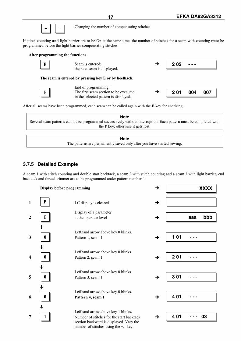
Changing the number of compensating stitches If stitch counting and light barrier are to be On at the same time, the number of stitches for a seam with counting must be programmed before the light barrier compensating stitches.
After programming the functions
Seam is entered; the next seam is displayed.
The seam is entered by pressing key E or by heelback.
End of programming ! The first seam section to be executed in the selected pattern is displayed.
After all seams have been programmed, each seam can be called again with the E key for checking.
Note Several seam patterns cannot be programmed successively without interruption. Each pattern must be completed with
the P key; otherwise it gets lost.
Note The patterns are permanently saved only after you have started sewing.
3.7.5 Detailed Example A seam 1 with stitch counting and double start backtack, a seam 2 with stitch counting and a seam 3 with light barrier, end backtack and thread trimmer are to be programmed under pattern number 4.
Display before programming
1 LC display is cleared
Display of a parameter 2 at the operator level
↓↓↓↓ Lefthand arrow above key 0 blinks. 3 Pattern 1, seam 1 ↓↓↓↓ Lefthand arrow above key 0 blinks. 4 Pattern 2, seam 1
↓↓↓↓ Lefthand arrow above key 0 blinks. 5 Pattern 3, seam 1
↓↓↓↓ Lefthand arrow above key 0 blinks. 6 Pattern 4, seam 1 ↓↓↓↓ Lefthand arrow above key 1 blinks. 7 Number of stitches for the start backtack section backward is displayed. Vary the number of stitches using the +/- key.
+ -
E 2 02 - - -
P 2 01 004 007
E aaa bbb
0 1 01 - - -
0 2 01 - - -
XXXX
P
0 3 01 - - -
0 4 01 - - -
1 4 01 - - - 03

EFKA DA82GA3312 18
↓↓↓↓ Righthand arrow above key 1 blinks. 8 Number of stitches for the start backtack section forward is displayed. Vary the number of stitches using the +/- key.
If a different key is pressed, start backtack section input is completed, and the righthand arrow above key 1 stops blinking. The double start backtack is enabled.
↓↓↓↓ Righthand arrow above key 6 On. 9 Sewing foot lift at the seam end is On.
↓↓↓↓ Lefthand arrow above key 2 On. 10 Stitch counting forward is On.
Change the number of stitches using the +/- keys, 11 or execute the seam section using the pedal.
Seam length is set at 17 stitches !
12 Pattern 4, seam 2 ↓↓↓↓ Lefthand arrow above key 2 On. 13 Stitch counting forward is On.
Change the number of stitches using the +/- keys, 14 or execute the seam section using the pedal.
Seam length is set at 8 stitches ! 15 Pattern 4, seam 3.
Free seam is selected. ↓↓↓↓ Lefthand arrow above key 3 On. 16 Light barrier covered/uncovered is On.
Change the number of stitches using the +/- keys; 17 5 compensating stitches are set.
↓↓↓↓ Lefthand arrow above key 4 blinks. 18 Number of stitches for the end backtack section backward is displayed. Vary the number of stitches using the +/- key.
If a different key is pressed, end backtack section input is completed, and the lefthand arrow above key 4 stops blinking. The single end backtack is enabled.
↓↓↓↓ ↓↓↓↓ Both arrows above key 5 On. 19 Thread trimmer and thread wiper are On.
Pattern 4, seam 4. 20 Advance to the next seam acknowledges the settings of the preceding seams.
Exit programming; 21 the first seam can be executed !
2 4 01 000
+ - 4 01 017
E 4 02 - - -
2 4 02 000
+ - 4 02 008
1 4 01 - - - 04
3 4 03 - - - 000
+ - 4 03 - - - 005
E 4 04 - - -
E 4 03 - - -
P 4 01 017
4
5 4 03 - - - 005
6 4 01 - - -
4 01 - - - 04

EFKA DA82GA3312 19 3.7.6 Maximum Number of Seams Exceeded If by inputting a program the total number of 40 seams is exceeded, the teach-in mode cannot be completed by pressing the P key. A new start of sewing is impaired. The display shows a warning (dEL). By pressing the P key again the pattern displayed will be deleted. Exit the teach-in mode now if the total number of 40 seams is not exceeded. Otherwise there will be a new warning.
Display:
X: Last input or selected pattern number (1...8) YY: Number of programmed seams of the selected pattern (0...40) NN: Total number of input seams if more than 40
The user must now decide which pattern should be deleted !
Selection of the pattern to be deleted
X: Pattern number YY: Number of seams of this pattern NN: Total number of input seams if more than 40
Deletion of the pattern
X: Pattern number of the deleted pattern YY: 00 = no more seam is programmed NN: Total number of input seams if more than 40
Exit the teach-in mode if the number of seams equals or falls below 40, and the last input seam will be displayed.
3.7.7 Execution (Pattern) Mode ↓↓↓↓
Enable mode by pressing key 0 1 (arrow above key 0 lights up). Seam number 01 is displayed.
Select pattern 1...8. 2
If you do not wish to start with seam 1, 3 press the E key several times until the desired seam number is displayed !
Start the pattern by pressing the pedal !
Complete the execution (pattern) mode; 4 Disable mode by pressing key 0!
3.7.8 Further Settings for TEACH IN
Functions Parameter
Seam suppression if 0 stitches are set (Std) 275
Parameter 275 = 0 Seam suppression disabled: i. e. if the light barrier is Off and stitch counting is set at 0 stitches, a
free seam will be performed.
dEL X YY NN
0 dEL X YY NN
P dEL X YY NN
0 X 01 ZZZ
+ - X 01 ZZZ
E X 05 ZZZ
0
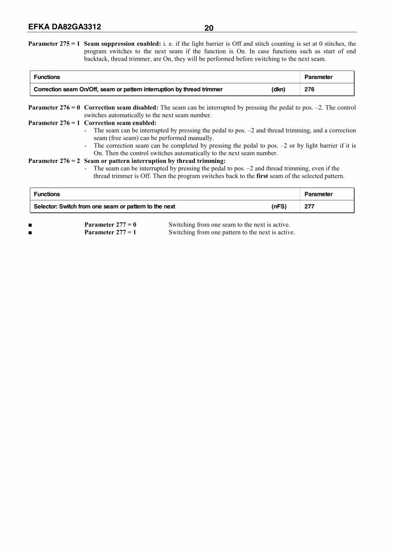
EFKA DA82GA3312 20 Parameter 275 = 1 Seam suppression enabled: i. e. if the light barrier is Off and stitch counting is set at 0 stitches, the
program switches to the next seam if the function is On. In case functions such as start of end backtack, thread trimmer, are On, they will be performed before switching to the next seam.
Functions Parameter
Correction seam On/Off, seam or pattern interruption by thread trimmer (dkn) 276
Parameter 276 = 0 Correction seam disabled: The seam can be interrupted by pressing the pedal to pos. –2. The control
switches automatically to the next seam number. Parameter 276 = 1 Correction seam enabled: - The seam can be interrupted by pressing the pedal to pos. –2 and thread trimming, and a correction seam (free seam) can be performed manually. - The correction seam can be completed by pressing the pedal to pos. –2 or by light barrier if it is On. Then the control switches automatically to the next seam number. Parameter 276 = 2 Seam or pattern interruption by thread trimming: - The seam can be interrupted by pressing the pedal to pos. –2 and thread trimming, even if the
thread trimmer is Off. Then the program switches back to the first seam of the selected pattern.
Functions Parameter
Selector: Switch from one seam or pattern to the next (nFS) 277
Parameter 277 = 0 Switching from one seam to the next is active. Parameter 277 = 1 Switching from one pattern to the next is active.

EFKA DA82GA3312 21 4 Putting into Service Before putting the control into service, the following must be ensured, checked and/or adjusted: The correct installation of the drive, position transmitter and accompanying devices, if necessary
If necessary, the correct adjustment of the direction of motor rotation using parameter 161
Verify using parameter 280 that the appropriate series is connected
The setting of the reference position using parameter 170
The setting of the positions using parameter 171
The correct positioning speed using parameter 110
The correct maximum speed compatible with the sewing machine using parameter 111
The setting of the remaining relevant parameters
Start sewing in order to save the set values
If the power is turned off before sewing has been started, the settings get lost! 5 Setting the Basic Functions 5.1 Direction of Motor Rotation
Functions Parameter
Direction of motor rotation (drE) 161
Parameter 161 = 0 Clockwise motor rotation Parameter 161 = 1 Counterclockwise motor rotation (look at the motor shaft)
5.2 Selection of the Machine Series
Functions Parameter
Display of the machine series (SEL) 280
The various machine models are specified by resistors. The following resistance values (tolerance ± 1%) are provided: Machine model = 271, N291, 8967 = 100Ω 204, 205, 221, 266, 366 = 220Ω 069, 267, 268, 269, 4180, 4280 = 680Ω 381, 382, 467, 767, 768 = 1000Ω
The special functional sequences for this machine type and the various preset values are activated depending on the resistor identified. The machine select is displayed using parameter 280. The resistance value is displayed in Ohm directly on the control panel.
ATTENTION If the motor is mounted differently, e. g. at a different angle or with gear, make sure
that the value set using parameter 161 corresponds to the direction of rotation.
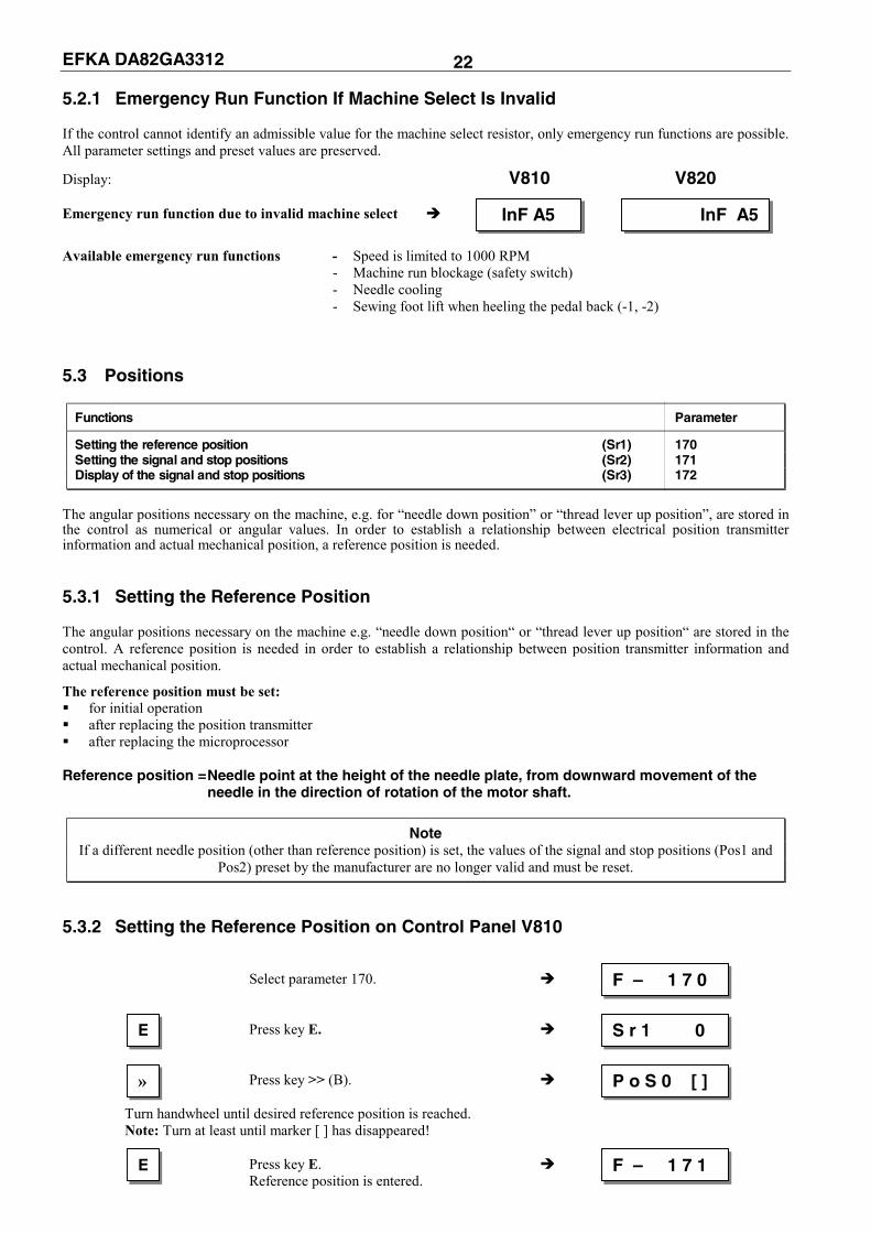
EFKA DA82GA3312 22 5.2.1 Emergency Run Function If Machine Select Is Invalid If the control cannot identify an admissible value for the machine select resistor, only emergency run functions are possible. All parameter settings and preset values are preserved.
Display: V810 V820 Emergency run function due to invalid machine select
Available emergency run functions - Speed is limited to 1000 RPM - Machine run blockage (safety switch) - Needle cooling - Sewing foot lift when heeling the pedal back (-1, -2)
5.3 Positions
Functions Parameter
Setting the reference position (Sr1) 170 Setting the signal and stop positions (Sr2) 171 Display of the signal and stop positions (Sr3) 172
The angular positions necessary on the machine, e.g. for “needle down position” or “thread lever up position”, are stored in the control as numerical or angular values. In order to establish a relationship between electrical position transmitter information and actual mechanical position, a reference position is needed. 5.3.1 Setting the Reference Position The angular positions necessary on the machine e.g. “needle down position“ or “thread lever up position“ are stored in the control. A reference position is needed in order to establish a relationship between position transmitter information and actual mechanical position.
The reference position must be set: for initial operation after replacing the position transmitter after replacing the microprocessor
Reference position = Needle point at the height of the needle plate, from downward movement of the
needle in the direction of rotation of the motor shaft.
Note If a different needle position (other than reference position) is set, the values of the signal and stop positions (Pos1 and
Pos2) preset by the manufacturer are no longer valid and must be reset. 5.3.2 Setting the Reference Position on Control Panel V810
Select parameter 170. Press key E. Press key >> (B). Turn handwheel until desired reference position is reached. Note: Turn at least until marker [ ] has disappeared! Press key E. Reference position is entered.
InF A5InF A5
F – 1 7 0
E S r 1 0
» P o S 0 [ ]
E F – 1 7 1
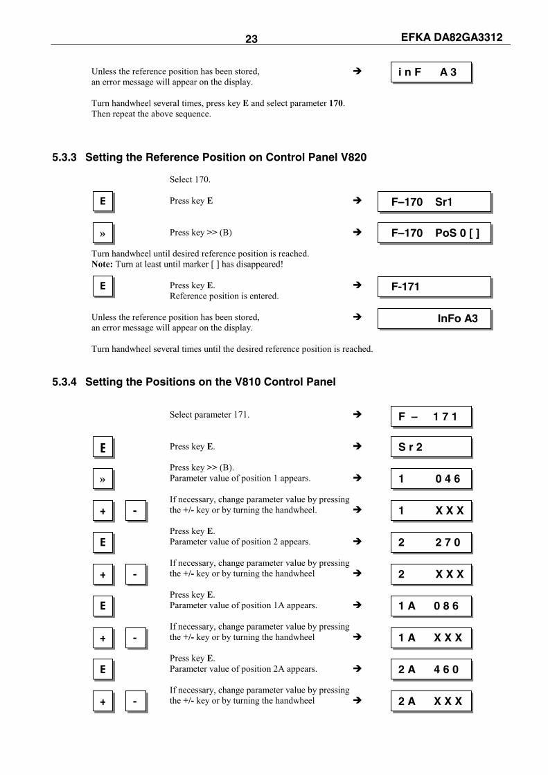
EFKA DA82GA3312 23 Unless the reference position has been stored, an error message will appear on the display. Turn handwheel several times, press key E and select parameter 170. Then repeat the above sequence.
5.3.3 Setting the Reference Position on Control Panel V820 Select 170. Press key E Press key >> (B) Turn handwheel until desired reference position is reached. Note: Turn at least until marker [ ] has disappeared! Press key E. Reference position is entered. Unless the reference position has been stored, an error message will appear on the display. Turn handwheel several times until the desired reference position is reached.
5.3.4 Setting the Positions on the V810 Control Panel Select parameter 171. Press key E. Press key >> (B). Parameter value of position 1 appears. If necessary, change parameter value by pressing the +/- key or by turning the handwheel. Press key E. Parameter value of position 2 appears. If necessary, change parameter value by pressing the +/- key or by turning the handwheel Press key E. Parameter value of position 1A appears. If necessary, change parameter value by pressing the +/- key or by turning the handwheel Press key E. Parameter value of position 2A appears. If necessary, change parameter value by pressing the +/- key or by turning the handwheel
F – 1 7 1
E S r 2
» 1 0 4 6
+ - 1 X X X
E 2 2 7 0
+ - 2 X X X
E 1 A 0 8 6
+ - 1 A X X X
E 2 A 4 6 0
+ - 2 A X X X
i n F A 3
E F–170 Sr1
E F-171
» F–170 PoS 0 [ ]
InFo A3

EFKA DA82GA3312 24
Press key E. Parameter value of position 3 appears on the display! Without function! Press key E. Parameter value of position 3A appears on the display! Without function!
Settings are completed. Exit programming.
5.3.5 Setting the Positions on the V820 Control Panel Display before programming Press key P. A parameter number blinks on the display. Input parameter number 171.
Press key E. The abbreviation of the parameter appears on the display.
Press key >> (B). Display of the 1st parameter value of position 1. If necessary, change parameter value by pressing the +/- keys or by turning the handwheel. Press key E. Parameter value of position 2 appears on the display. If necessary, change parameter value by pressing the +/- keys or by turning the handwheel. Press key E. Parameter value of position 1A appears on the display. If necessary, change parameter value by pressing the +/- keys or by turning the handwheel. Press key E. Parameter value of position 2A appears on the display. If necessary, change parameter value by pressing the +/- keys or by turning the handwheel.
Press key E. Parameter value of position 3 appears on the display! Without function!
Press key E. Parameter value of position 3 appears on the display! Without function! Settings are completed. Exit programming.
P P d A 8 2 G A
1 7 F-171 1
E F-171 Sr2
+ F-171 1 XXX -
4000 dA82GA
P F–XXX
» F-171 1 046
E F-171 2 270
E 3 A 0 0 0
E 3 0 0 0
+ F-171 2 XXX -
E F-171 1A 086
+ F-171 1A XXX -
E F-171 2A 460
+ F-171 2A XXX -
E F–171 3 000
P P 4000 dA82GA
E F–171 3A 000
EFKA DA82GA3312 25
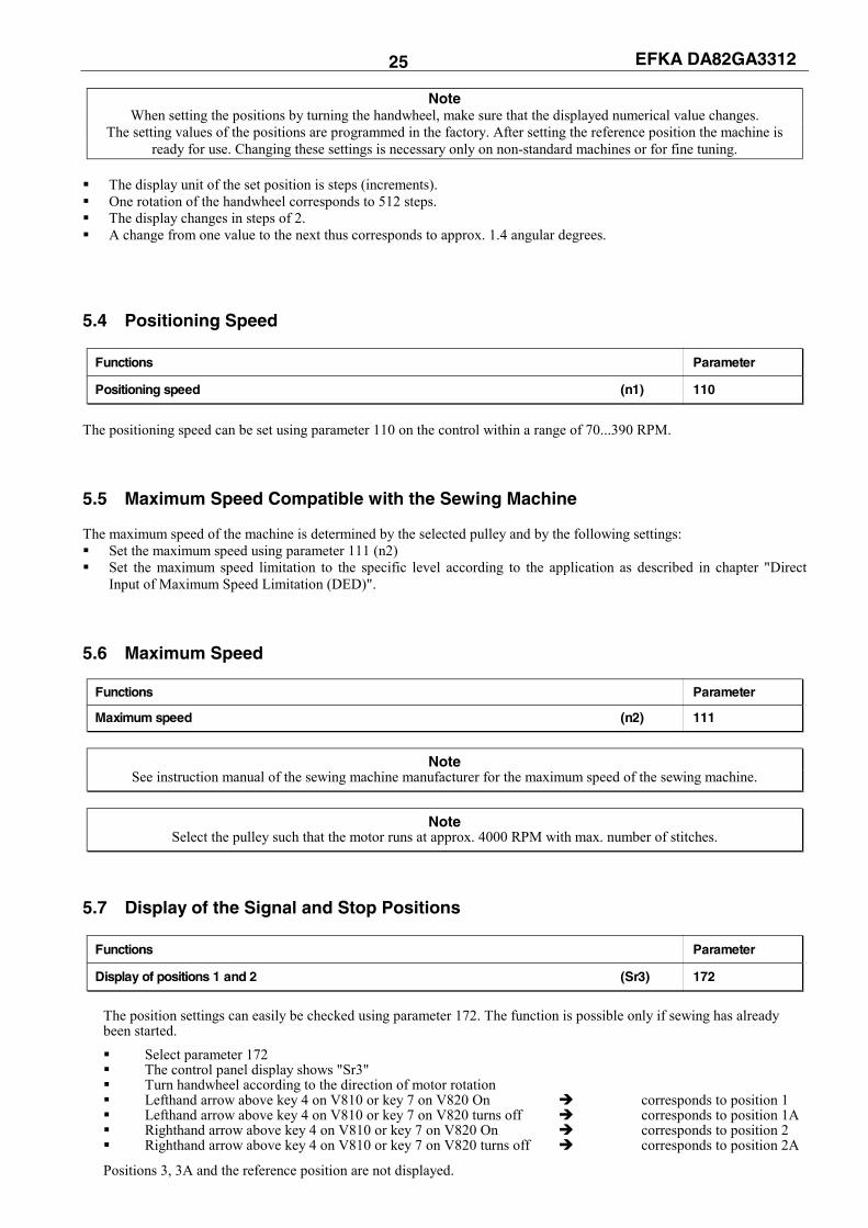
Note When setting the positions by turning the handwheel, make sure that the displayed numerical value changes.
The setting values of the positions are programmed in the factory. After setting the reference position the machine is ready for use. Changing these settings is necessary only on non-standard machines or for fine tuning.
The display unit of the set position is steps (increments). One rotation of the handwheel corresponds to 512 steps. The display changes in steps of 2. A change from one value to the next thus corresponds to approx. 1.4 angular degrees.
5.4 Positioning Speed
Functions Parameter
Positioning speed (n1) 110
The positioning speed can be set using parameter 110 on the control within a range of 70...390 RPM. 5.5 Maximum Speed Compatible with the Sewing Machine The maximum speed of the machine is determined by the selected pulley and by the following settings: Set the maximum speed using parameter 111 (n2) Set the maximum speed limitation to the specific level according to the application as described in chapter "Direct
Input of Maximum Speed Limitation (DED)". 5.6 Maximum Speed
Functions Parameter
Maximum speed (n2) 111
Note
See instruction manual of the sewing machine manufacturer for the maximum speed of the sewing machine.
Note Select the pulley such that the motor runs at approx. 4000 RPM with max. number of stitches.
5.7 Display of the Signal and Stop Positions
Functions Parameter
Display of positions 1 and 2 (Sr3) 172
The position settings can easily be checked using parameter 172. The function is possible only if sewing has already been started. Select parameter 172 The control panel display shows "Sr3" Turn handwheel according to the direction of motor rotation Lefthand arrow above key 4 on V810 or key 7 on V820 On corresponds to position 1 Lefthand arrow above key 4 on V810 or key 7 on V820 turns off corresponds to position 1A Righthand arrow above key 4 on V810 or key 7 on V820 On corresponds to position 2 Righthand arrow above key 4 on V810 or key 7 on V820 turns off corresponds to position 2A
Positions 3, 3A and the reference position are not displayed.

EFKA DA82GA3312 26 5.8 Braking Characteristics
Functions Parameter
Braking effect when varying the preset value ≤ 4 stages (br1) 207 Braking effect when varying the preset value ≥ 5 stages (br2) 208 Machine selection: 0 = normal, 1 = medium duty, 2 = heavy duty, (rEG) 225 3 = models 4180 and 4280
Parameter 207 regulates the braking effect between speed stages Parameter 208 influences the braking effect for the stop
The following applies to all setting values: The higher the value, the stronger the braking reaction! 5.9 Braking Power at Standstill
Functions Parameter
Braking power at standstill (brt) 153
This function prevents unintentional "wandering" of the needle at standstill. The effect can be checked by turning the handwheel. The braking power is effective at standstill
- at stop in the seam – after the seam end
The effect can be set The higher the set value, the stronger the braking power It does not work after power On,
5.10 Starting Characteristics
Functions Parameter
Accelerating power of the drive (ALF) 220
The drive acceleration dynamics can be adapted to the sewing machine characteristic (light/heavy). High setting value = high acceleration
With a high starting edge setting and, in addition, possibly high braking parameter values on a light machine, the characteristic may appear coarse. In this case, one should try to optimize the settings. 5.11 Actual Speed Display
Functions Parameter
Actual speed display (nIS) 139
If parameter 139 = ON, the V810/820 display shows the following information:
During operation: The actual speed Example: 2350 revolutions per minute
At stop in the seam: The stop indication
At standstill after trimming: On the V810, indication of the type of control On the V820, indication of the set maximum speed
and the type of control Example: 3300 revolutions per minute and type of control DA320G
23502350
3300 dA82GA dA82GA
StoP StoP

EFKA DA82GA3312 27 6 Functions and Settings 6.1 First Stitch after Power On
Functions Parameter
1 stitch at positioning speed after power On (Sn1) 231
For the protection of the sewing machine and if parameter 231 is On, the first stitch after power On will be performed at positioning speed n1, independently of the pedal position and the softstart function. 6.2 Softstart
Functions Parameter
Softstart On/Off (SSt) 134
Functions: after power on at the beginning of a new seam speed pedal controlled and limited to (n6) lower speed of a parallel function prevailing (e. g. start backtack, stitch counting) stitch counting synchronized to position 1 suspension with pedal in position 0 (neutral) / interruption by full heelback (position -2)
When using the V820 control panel, direct access is possible by means of the function key (key 9)!
Functions Parameter
Softstart On/Off (-F-) 008 = 1
6.2.1 Softstart Speed
Function with or without control panel Parameter
Softstart speed (n6) 115
6.2.2 Softstart Stitches
Functions Parameter
Number of softstart stitches (SSc) 100
6.3 Sewing Foot Lifting
Functions V810 V820
Sewing foot lifting at stop in the seam lefthand arrow above key On Key 3 Key 6 (automatic) Sewing foot lifting after thread trimming righthand arrow above key On (automatic) Sewing foot lifting at stop in the seam and both arrows above key On after thread trimming (automatic) Sewing foot lifting Off both arrows above key Off
EFKA DA82GA3312 28
Functions Parameter
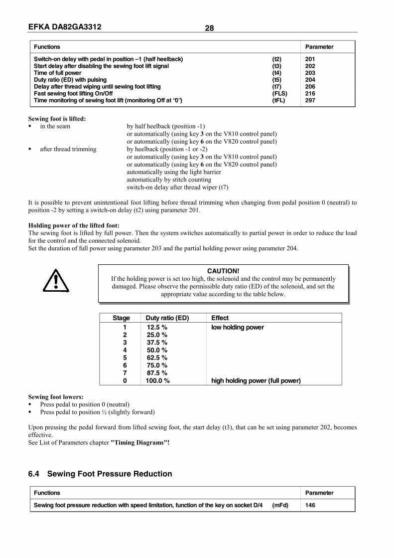
Switch-on delay with pedal in position –1 (half heelback) (t2) 201 Start delay after disabling the sewing foot lift signal (t3) 202 Time of full power (t4) 203 Duty ratio (ED) with pulsing (t5) 204 Delay after thread wiping until sewing foot lifting (t7) 206 Fast sewing foot lifting On/Off (FLS) 216 Time monitoring of sewing foot lift (monitoring Off at “0”) (tFL) 297
Sewing foot is lifted: in the seam by half heelback (position -1)
or automatically (using key 3 on the V810 control panel) or automatically (using key 6 on the V820 control panel)
after thread trimming by heelback (position -1 or -2) or automatically (using key 3 on the V810 control panel) or automatically (using key 6 on the V820 control panel) automatically using the light barrier automatically by stitch counting switch-on delay after thread wiper (t7)
It is possible to prevent unintentional foot lifting before thread trimming when changing from pedal position 0 (neutral) to position -2 by setting a switch-on delay (t2) using parameter 201. Holding power of the lifted foot: The sewing foot is lifted by full power. Then the system switches automatically to partial power in order to reduce the load for the control and the connected solenoid. Set the duration of full power using parameter 203 and the partial holding power using parameter 204.
Stage Duty ratio (ED) Effect 1 12.5 % low holding power 2 25.0 % 3 37.5 % 4 50.0 % 5 62.5 % 6 75.0 % 7 87.5 % 0 100.0 % high holding power (full power)
Sewing foot lowers: Press pedal to position 0 (neutral) Press pedal to position ½ (slightly forward)
Upon pressing the pedal forward from lifted sewing foot, the start delay (t3), that can be set using parameter 202, becomes effective. See List of Parameters chapter "Timing Diagrams"! 6.4 Sewing Foot Pressure Reduction
Functions Parameter
Sewing foot pressure reduction with speed limitation, function of the key on socket D/4 (mFd) 146
CAUTION! If the holding power is set too high, the solenoid and the control may be permanently damaged. Please observe the permissible duty ratio (ED) of the solenoid, and set the
appropriate value according to the table below.

EFKA DA82GA3312 29 The sewing foot pressure consists of a basic value generated by spring power and a value generated pneumatically. After power On, the sewing foot always works at full pressure. The sewing foot pressure can be reduced by pressing the key connected to socket D/4-15. The sewing foot pressure output is disabled. It is enabled by pressing the key again. The reduced sewing foot pressure is indicated by a light emitting diode. At reduced sewing foot pressure the speed is limited depending on parameter 146. Speed limitation DB2000 or DB3000 can be selected using parameter 146. Moreover, it is possible to select inverted sewing foot pressure reduction. Normal sewing foot pressure can be enabled by pressing the key again. The key can be pressed at any time except during automatic seams or seam sections. The sewing foot lift does not have influence on the sewing foot pressure. Parameter 146 = 1 Sewing foot pressure reduction with speed limitation DB2000 Parameter 146 = 2 Sewing foot pressure reduction with speed limitation DB3000 Parameter 146 = 3 Lift roller (see chapter “Roller“) Parameter 146 = 4 Inverted sewing foot pressure reduction 6.5 Start Backtack
Functions V810/V820
Single start backtack lefthand arrow above key On Key 1 Double start backtack righthand arrow above key On Start backtack Off both arrows Off
The start backtack starts by pressing the pedal forward at the beginning of the seam. From lifted sewing foot the backtack is delayed by the time t3 (start delay after disabling the sewing foot lift signal). The start backtack is executed automatically at speed n3. If softstart is running parallel, the respective lower speed is prevailing. Whether or not an interruption of the start and end backtack is possible can be determined with parameter 284. It does not work with the ornamental backtack. Parameter 284 = ON Backtack can be interrupted by pedal position 0 (neutral). A separate speed using parameter 125 is available for this purpose. Parameter 284 = OFF Automatic backtack cannot be interrupted By pressing the pedal forward after an interrupted start backtack, the backtack can be continued; by half heelback (-1), the the sewing foot can be lifted, or, by full heelback (-2), trimming without end backtack can be completed. The sewing foot is not automatically lifted when interrupting the backtack.
The start backtack stitch length is set with the following parameter: Parameter 137 = ON Backtack is performed with normal stitch length. Parameter 137 = OFF Backtack is performed with long stitches. The stitch length (normal or long stitches) during backtack can be selected with parameter 137. The indicator does not light up during backtack. Counting as well as enabling and disabling of the backtacking signal is synchronized to position 1. The backtacking signal will be disabled after completion of the backward section (parameter 001) and start backtack speed n3 after a delay time t1. Then pedal control is returned. 6.5.1 Speed n3 at the Start of the Seam
Functions Parameter
Start backtack speed (n3) 112
When programming 3-digit or 4-digit parameter values on the control, the 2-digit or 3-digit values displayed must be multiplied by 10. 6.5.2 Start Backtacking Stitch Count
Functions Parameter
Number of stitches forward (Arv) 000 Number of stitches backward (Arr) 001

EFKA DA82GA3312 30 The number of start backtacking stitches can be set using the above parameters directly on the V810/V820 control panel. For fast operator information (HIT) when using the V820 control panel, the value of the function enabled using key 1 can be displayed for approx. 3 seconds. During this time, the value can be varied directly by pressing key + or -. 6.5.3 Speed Release
Functions Parameter
Delay until speed release after start backtack (t1) 200
Speed release after single and double backtack can be influenced by parameter 200. 6.5.4 Double Start Backtack The forward section will be sewn for a number of stitches that can be set. Then the stitch regulator signal will be issued and the backward section will be executed. The number of stitches for the two sections can be set separately. 6.5.5 Single Start Backtack The stitch regulator signal will be issued and the backward section will be executed for a number of stitches that can be set. 6.6 End Backtack
Functions V810 V820
Single end backtack lefthand arrow above key On Key 2 Key 4 Double end backtack righthand arrow above key On End backtack Off both arrows Off
The end backtack starts by heelback, in a seam with stitch counting at the end of counting, or, from the light barrier seam at the end of the light barrier compensating stitches. The stitch regulator is immediately enabled from machine standstill. After lowering the sewing foot, the switch-on point of the stitch regulator is delayed by the time t3 (start delay after disabling the sewing foot lift signal). The first leading edge of position 1 counts as 0 stitch whenever the function is not started in position 1. Counting and disabling the stitch regulator is synchronized to position 1. From full machine run, the signal will be switched in only after having reached the end backtack speed n4 and synchronization to position 2. Whether or not an interruption of the start and end backtack is possible can be determined with parameter 284. It does not work with the ornamental backtack. Parameter 284 = ON Backtack can be interrupted by pedal position 0 (neutral). A separate speed using parameter
126 is available for this purpose. Parameter 284 = OFF Automatic backtack cannot be interrupted By pressing the pedal forward after an interrupted end backtack, the backtack can be continued; by half heelback (-1), the the sewing foot can be lifted, or, by full heelback (-2), trimming without end backtack can be completed. The sewing foot is not automatically lifted when interrupting the backtack.
The end backtack stitch length is set with the following parameter: Parameter 137 = ON Backtack is performed with normal stitch length. Parameter 137 = OFF Backtack is performed with long stitches. The stitch length (normal or long stitches) during backtack can be selected with parameter 137. The indicator does not light up during backtack. 6.6.1 Speed n4 at the Seam End
Functions Parameter
End backtack speed (n4) 113

EFKA DA82GA3312 31 6.6.2 End Backtacking Stitch Count
Functions Parameter
Number of stitches backward (Err) 002 Number of stitches forward (Erv) 003
The number of end backtacking stitches can be set using the above parameters directly on the V810/V820 control panel. For fast operator information (HIT) when using the V820 control panel, the value of the function enabled using key 4 can be displayed for approx. 3 seconds. During this time, the value can be varied directly by pressing key + or -. 6.6.3 Last Stitch Backward
Functions Parameter
Last stitch backward On/Off (FAr) 136
For some sewing procedures it is desirable that the backtack solenoid in the single end backtack is disabled only after trimming. This function can be selected using parameter 136 and works only in the single end backtack. Parameter 136 = 0 Trimming stitch forward and thread wiper function On. Parameter 136 = 1 Trimming stitch backward and thread wiper function On. Parameter 136 = 2 Trimming stitch forward with short trimmer signal On. Thread wiper function Off. Parameter 136 = 3 Trimming stitch forward with signal for stitch length reduction during softstart and
signal for short trimmer On. Thread wiper function Off. Parameter 136 = 4 Trimming stitch forward with signal for stitch length reduction during softstart.
Thread wiper function Off. 6.6.4 Double End Backtack The backward section will be executed for a number of stitches that can be set. Then the stitch regulator will be disabled and the forward section will be executed. The number of stitches for the two sections can be set separately. After stitch counting (parameter 003) the trimming function will be initiated. During the entire operation the sewing speed is reduced to speed n4, with the exception of the last stitch, which will be performed at positioning speed n1. 6.6.5 Single End Backtack The single end backtack is performed at end backtack speed (n4). During the last stitch the speed is reduced to positioning speed. The stitch regulator remains On or is disabled depending on parameter 136. 6.6.6 Backtack Synchronization
Function Parameter
Backtack synchronization for start and end backtack On/Off (nSo) 123 Backtack synchronization speed (nrS) 124
If parameter 123 is on, the backtack speed will be switched to backtack synchronization speed one stitch before engaging and disengaging of the backtack solenoid. The backtack speed is released at the next position 2. If the synchronization speed, that can be set using parameter 124, is higher than the backtack speed, the latter is maintained. Backtack synchronization is possible in the start and end backtack. 6.7 Start and End Backtack with Switch-On and Switch-Off Delay It is possible to compensate inertia of the start and end backtack system by parameter setting. Use parameter 101 and 102 for the start backtack and parameter 103 and 104 for the end backtack.
EFKA DA82GA3312 32
Functions Parameter
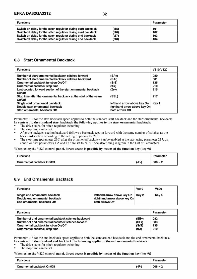
Switch-on delay for the stitch regulator during start backtack (t15) 101 Switch-off delay for the stitch regulator during start backtack (t16) 102 Switch-on delay for the stitch regulator during end backtack (t17) 103 Switch-off delay for the stitch regulator during end backtack (t18) 104
6.8 Start Ornamental Backtack
Functions V810/V820
Number of start ornamental backtack stitches forward (SAv) 080 Number of start ornamental backtack stitches backward (SAr) 081 Ornamental backtack function On/Off (SrS) 135 Ornamental backtack stop time (tSr) 210 Last counted forward section of the start ornamental backtack (Zrv) 215 On/Off Stop time after the ornamental backtack at the start of the seam (SSL) 217 On/Off Single start ornamental backtack lefthand arrow above key On Key 1 Double start ornamental backtack righthand arrow above key On Start ornamental backtack Off both arrows Off
Parameter 112 for the start backtack speed applies to both the standard start backtack and the start ornamental backtack. In contrast to the standard start backtack the following applies to the start ornamental backtack: The drive stops for stitch regulator switching. The stop time can be set. After the backtack section backward follows a backtack section forward with the same number of stitches as the
backward section according to the setting of parameter 215. The stop time (parameter 210) after the ornamental backtack can be enabled at the start using parameter 217, on
condition that parameters 135 and 137 are set to “ON”. See also timing diagram in the List of Parameters.
When using the V820 control panel, direct access is possible by means of the function key (key 9)!
Functions Parameter
Ornamental backtack On/Off (-F-) 008 = 2
6.9 End Ornamental Backtack
Functions V810 V820
Single end ornamental backtack lefthand arrow above key On Key 2 Key 4 Double end ornamental backtack righthand arrow above key On End ornamental backtack Off both arrows Off
Functions Parameter
Number of end ornamental backtack stitches backward (SEv) 082 Number of end ornamental backtack stitches forward (SEr) 083 Ornamental backtack function On/Off (SrS) 135 Ornamental backtack stop time (tSr) 210
Parameter 113 for the end backtack speed applies to both the standard end backtack and the end ornamental backtack. In contrast to the standard end backtack the following applies to the end ornamental backtack: The drive stops for stitch regulator switching The stop time can be set
When using the V820 control panel, direct access is possible by means of the function key (key 9)!
Functions Parameter
Ornamental backtack On/Off (-F-) 008 = 2
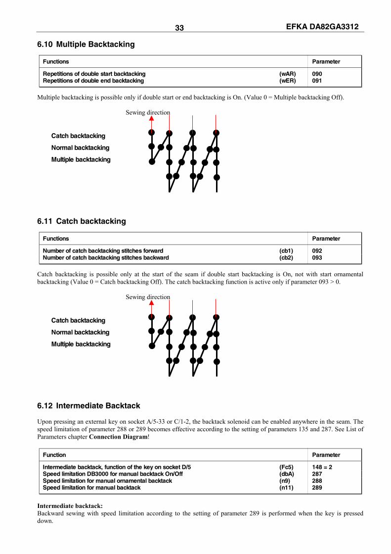
EFKA DA82GA3312 33 6.10 Multiple Backtacking
Functions Parameter
Repetitions of double start backtacking (wAR) 090 Repetitions of double end backtacking (wER) 091
Multiple backtacking is possible only if double start or end backtacking is On. (Value 0 = Multiple backtacking Off). Sewing direction
¬ − ® ¬ Catch backtacking
− Normal backtacking
® Multiple backtacking 6.11 Catch backtacking
Functions Parameter
Number of catch backtacking stitches forward (cb1) 092 Number of catch backtacking stitches backward (cb2) 093
Catch backtacking is possible only at the start of the seam if double start backtacking is On, not with start ornamental backtacking (Value 0 = Catch backtacking Off). The catch backtacking function is active only if parameter 093 > 0. Sewing direction
¬ − ® ¬ Catch backtacking
− Normal backtacking
® Multiple backtacking 6.12 Intermediate Backtack Upon pressing an external key on socket A/5-33 or C/1-2, the backtack solenoid can be enabled anywhere in the seam. The speed limitation of parameter 288 or 289 becomes effective according to the setting of parameters 135 and 287. See List of Parameters chapter Connection Diagram!
Function Parameter
Intermediate backtack, function of the key on socket D/5 (Fc5) 148 = 2 Speed limitation DB3000 for manual backtack On/Off (dbA) 287 Speed limitation for manual ornamental backtack (n9) 288 Speed limitation for manual backtack (n11) 289
Intermediate backtack: Backward sewing with speed limitation according to the setting of parameter 289 is performed when the key is pressed down.

EFKA DA82GA3312 34 Intermediate ornamental backtack: By pressing the key in the seam, the drive stops and the backtack solenoid is activated. The speed limitation according to the setting of parameter 288 is effective during the entire intermediate backtack operation. Backward sewing is performed when the key is pressed down and the stitches are counted. When releasing the key, the drive stops, the backtack solenoid is disabled and a forward seam is performed according to the counted stitches after the ornamental backtack stop time. After that the speed limitation is released. 6.13 Backtack Suppression/Recall Effective in standard and ornamental backtack
The next backtack operation can be suppressed or recalled once by pressing an external key on socket A/14-33. This is acknowledged by a light emitting diode connected to socket A/24. It goes off when the backtack function is completed or the key is pressed again.
Function Parameter
Backtack suppression/recall, function of the key on socket D/3 (Fc3) 147 = 2
Upon pressing Start backtack Start backtack End backtack End backtack On On On On
Before start of No backtack Backtack --- --- seam
In the seam --- --- No backtack Backtack
The double backtack is performed in the above cases. See List of Parameters chapter Connection Diagram! 6.14 Holding Power of the Stitch Regulator Solenoid
Function Parameter
Time of full power (t10) 212 Holding power of the stitch regulator solenoid (t11) 213
The stitch regulator solenoid is engaged by full power. Then the system switches automatically to partial power in order to reduce the load for the control and the connected solenoid. Set the duration of full power using parameter 203 and the partial holding power using parameter 204.
Stage Duty ratio (ED) Effect 1 12.5 % low holding power 2 25.0 % 3 37.5 % 4 50.0 % 5 62.5 % 6 75.0 % 7 87.5 % 0 100.0 % high holding power (full power)
CAUTION! If the holding power is set too high, the solenoid and the control may be permanently damaged. Please observe the permissible duty ratio (ED) of the solenoid and set the
appropriate value according to the table below.

EFKA DA82GA3312 35 6.15 Reverse Motor Rotation
Functions Parameter
Positioning speed (n1) 110 Number of increments in reverse motor rotation (ird) 180 Switch-on delay of reverse motor rotation (drd) 181 Reverse motor rotation On/Off (Frd) 182
The function "reverse motor rotation" is performed after trimming. When the stop position is reached, the drive stops for the duration of the switch-on delay of reverse motor rotation (parameter 182). Then it runs in reverse direction at positioning speed for an adjustable number of increments (1 increment corresponds to approx. 0.7°). After reverse motor rotation the thread wiper will be activated for the time t6.
When using the V820 control panel, direct access is possible by means of the function key (key 9)!
Function Parameter
Reverse motor rotation On/Off (-F-) 008 = 5
6.16 Machine Run Blockage (Safety Switch)
Functions Parameter
New sewing start after machine run blockage (PdO) 281 Functioning of the switch for machine run blockage (LOS) 282 Function “machine run blockage” (LSP) 283
Select how the drive is restarted after deactivating machine run blockage using parameter 281. Parameter 281 = 0 Immediate start from any pedal position Parameter 281 = 1 Start only with pedal in position 0 (neutral) Determine the functioning of the safety switch using parameter 282. Parameter 282 = 0 Make contact [N.O.] (switch closed = machine run blockage On) Parameter 282 = 1 Break contact [N.C.] (switch open = machine run blockage On) Switch the function “machine run blockage” using parameter 283. Parameter 283 = 0 Machine run blockage Off Parameter 283 = 1 Function “machine run blockage” 1 (safety function) fastest stop without positioning Parameter 283 = 2 Function “machine run blockage” 2 (control function) with positioning in the actual position The function “machine run blockage” is enabled by connecting a switch to socket A/11-33 or B/2-3. When using a V810 / V820 control panel, an acoustic signal can be enabled or disabled using parameter 127. Display and signal after enabling machine run blockage on the control panel: V810 control panel display (symbol blinks and acoustic signal if parameter 127 = 1) V820 control panel display (symbol blinks and acoustic signal if parameter 127 = 1) In all variants of the function “machine run blockage” sewing foot lifting is possible, needle up/down or its variants, however, is not.
CAUTION! This is not a safety function. The line voltage must still be switched off during
maintenance and repair work.
-S t o P-

EFKA DA82GA3312 36 6.16.1 Machine Start Blockage (Blockage 1 and 2) If the input “machine run blockage“ is activated at machine standstill, the run of the drive is blocked despite pressing the pedal. Machine start is possible only after deactivating the input. 6.16.2 Function “Machine Run Blockage” 1 (Safety Function) Parameter 283 = 1 In the start backtack: Fastest stop without positioning. The start backtack will be interrupted. Trimming is impossible. After deactivating the machine run blockage the start backtack and the seam will be continued by pressing the pedal to
position >1, or thread trimming will be initiated by full heelback (–2). In the free seam: Fastest stop without positioning. Trimming is impossible. After deactivating the machine run blockage the seam will be continued by pressing the pedal to position >1, or thread
trimming will be initiated by full heelback (–2). During stitch counting: Fastest stop without positioning. Stitch counting will be interrupted. Trimming is impossible. After deactivating the machine run blockage stitch counting will be continued by pressing the pedal to position >1, or
thread trimming will be initiated by full heelback (–2). During the light barrier compensating stitches: Fastest stop without positioning. The light barrier compensating stitches will be interrupted. Trimming is impossible. After deactivating the machine run blockage the light barrier compensating stitches will be continued by pressing the
pedal to position >1, or thread trimming will be initiated by full heelback (–2). In the end backtack: Fastest stop without positioning. The end backtack will be interrupted. Trimming is impossible. After deactivating the machine run blockage the end backtack will be continued by pressing the pedal to position >1,
or thread trimming will be initiated by full heelback (–2). 6.16.3 Function “Machine Run Blockage” 2 (Control Function) Parameter 283 = 2 In the start backtack, during stitch counting and the light barrier compensating stitches: Stop in the selected position. Trimming without end backtack by full heelback is possible when machine run blockage is On. In this case, a new
seam will be started after deactivating machine run blockage. After deactivating the machine run blockage the start backtack or stitch counting will be continued by pressing the
pedal to position >1, or thread trimming will be initiated by full heelback (–2). In the free seam: Stop in the selected position. Trimming without end backtack by full heelback is possible when machine run blockage is On. In this case, a new
seam will be started after deactivating machine run blockage. After deactivating the machine run blockage the seam will be continued by pressing the pedal to position >1, or thread
trimming will be initiated by full heelback (–2). In the end backtack: The end backtack will be completed with a stop in the selected position. The start of the next seam is blocked. Trimming by full heelback is possible when machine run blockage is On. After deactivating the machine run blockage the sewing operation will be completed by thread trimming by half
heelback, unless the thread has been trimmed before. If the thread is trimmed when machine run blockage is On, a new seam will be started after deactivating the machine
run blockage. During thread trimming: Thread trimming will be completed. The start of the next seam is blocked. After deactivating the machine run blockage the start of the next seam is possible.

EFKA DA82GA3312 37 6.17 Thread Monitor
Functions Parameter
Number of thread monitor stitches (cFw) 085 Thread monitor mode (rFw) 195
If the thread monitor function is On (parameter 195 = 1...4), the type of control and the set maximum speed are displayed for 1 sec. After power On.
Display of maximum speed: Type of control (e. g. 4000 RPM)
Then the thread monitor status display appears. Number of thread monitor stitches: Status display (e. g. 250 stitches) At this point (after power On) the number of stitches can be regulated in steps of 10 using the +/- key. The function DED = Direct Input of Speed Limitation is available only after having started sewing or trimming. 6.17.1 Input Signals The form of input signal helps distinguish which of the bobbins is empty. Righthand bobbin empty: = Continuous signal (min. 1 sec.) Lefthand bobbin empty: = Frequency 5 Hz or signal for approx. 100 msec Lefthand and righthand bobbin empty: = Frequency 10 Hz or signal for approx. 50 msec 6.17.2 Parameter 195 = 0 – No Thread Monitor Function The thread monitor function is Off. 6.17.3 Parameter 195 = 1 – Model 270 / No Stop / Sewing Foot Down after Seam End After the bobbin is empty, the bobbin thread counter is activated when receiving an input signal, and the thread monitor symbol blinks on the display of the V810 or V820 control panel. After counting, C is displayed for the lefthand bobbin and D for the righthand bobbin on the V810 control panel. On the V820 control panel, another symbol for the righthand, lefthand bobbin or both bobbins is displayed instead of the type designation. Furthermore, the respective LEDs blink with approx. 4 Hz on the machine (righthand, lefthand or both). The displays remain on even if the input signal is no longer received. The sewing foot is not lifted after thread trimming and after counting. The sewing foot is lifted only after the pedal has been heeled back from position 0 (neutral). The displays go off (the blinking frequency of 4 Hz is disabled), if no more input signals are received after thread trimming and the subsequent sewing start after 14 stitches. This is an indicator that the bobbin has been replaced, and the bobbin thread counter is reset to zero. 6.17.4 Parameter 195 = 2 – Model 767, N291 / With Stop / Sewing Foot Up after Seam
End After the bobbin is empty, the bobbin thread counter is activated when receiving an input signal, and the thread monitor symbol blinks on the display of the V810 or V820 control panel. After counting, C is displayed for the lefthand bobbin and D for the righthand bobbin on the V810 control panel. On the V820 control panel, another symbol for the righthand, lefthand bobbin or both bobbins is displayed instead of the type designation. Furthermore, the respective LEDs blink with approx. 4 Hz on the machine (righthand, lefthand or both), and the drive stops. Even automatic seam sections like seams with stitch counting or light barrier seams are interrupted. They can be completed by pressing the pedal forward from position 0 (neutral). Note the following exceptions: If bobbin thread counting is completed in the start backtack, the latter will be completed and the drive stops. If bobbin thread counting is completed in the end backtack, the latter will be fully completed with the thread trimming
operation. After thread trimming the sewing foot is automatically lifted. The displays go off (the blinking frequency of 4 Hz is disabled), if no more input signals are received after thread trimming and the subsequent sewing start after 14 stitches. This is an indicator that the bobbin has been replaced, and the bobbin thread counter is reset to zero.
4000 dA82GA
250 --II--
EFKA DA82GA3312 38 6.17.5 Parameter 195 = 3 – Model 767, N291 / With Stop / Sewing Foot Down after Seam
End Functions as with parameter 195 = 2, but the sewing foot is lifted after thread trimming only after the pedal has been heeled back from position 0 (neutral). 6.17.6 Parameter 195 = 4 – With Thread Monitor Stitch Counting By pressing a key connected to socket A/12-33, a stitch counter is activated (max. 9990 stitches), and the thread monitor symbols are continuously displayed. When a V820 control panel is connected, the function can be activated using key 8. At each intermediate stop, the remaining number of stitches will be displayed. When counting is completed, the thread monitor symbol (righthand or lefthand) blinks on the display of the V820 control panel. C is displayed for the lefthand bobbin and D for the righthand bobbin on the V810 control panel. Furthermore, the respective LEDs blink with approx. 4 Hz on the machine, and the drive stops. Even automatic seam sections, except start and end backtack, are interrupted. The seam can be continued by pressing the pedal forward from position 0 (neutral). The number of stitches is set such that after completing these stitches, the bobbin is not completely empty. After replacing the bobbin, the key must be pressed so that the counter is reset to the preset value and activated again. If the drive is turned off during thread monitor counting, this value is saved and counting is continued after power On. If the key is pressed for less than one second, the counter is set to the preset value. Key pressed >1 sec. Thread monitor function is deactivated/activated Key pressed <1 sec. Counter is set to the preset value 6.18 Needle Cooling
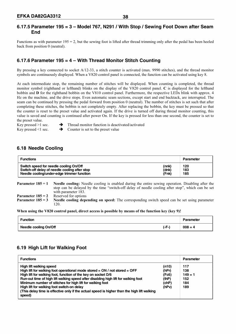
Functions Parameter
Switch speed for needle cooling On/Off (nnk) 120 Switch-off delay of needle cooling after stop (dnk) 183 Needle cooling/under-edge trimmer function (Fnk) 185
Parameter 185 = 1 Needle cooling: Needle cooling is enabled during the entire sewing operation. Disabling after the
stop can be delayed by the time “switch-off delay of needle cooling after stop”, which can be set with parameter 183.
Parameter 185 = 2 Reserved for options Parameter 185 = 3 Needle cooling depending on speed: The corresponding switch speed can be set using parameter
120.
When using the V820 control panel, direct access is possible by means of the function key (key 9)!
Function Parameter
Needle cooling On/Off (-F-) 008 = 4
6.19 High Lift for Walking Foot
Functions Parameter
High lift walking speed (n10) 117 High lift for walking foot operational mode stored = ON / not stored = OFF (hPr) 138 High lift for walking foot, function of the key on socket D/6 (Fc6) 149 = 1 Run-out time of high lift walking speed after disabling high lift for walking foot (thP) 152 Minimum number of stitches for high lift for walking foot (chP) 184 High lift for walking foot switch-on delay (hPv) 189 (This delay time is effective only if the actual speed is higher than the high lift walking speed)

EFKA DA82GA3312 39 6.19.1 Manual High Lift for Walking Foot – Speed Limitation The high lift during sewing can be set on a handwheel intended for this. The high lift shaft in the machine is hereby turned. The position of the high lift shaft is queried by means of a turn switch, which limits the maximum machine speed to DB3000 in position 1 and to DB2000 in position 2. 6.19.2 Maximum High Lift for Walking Foot by Using a Key By pressing the key connected to socket A/7-33 or D/6-15 (parameter 149 = 1) or B/1-2, high lift for walking foot and a light emitting diode are enabled. The maximum speed is limited to the high lift walking speed (DB2000). If the actual speed is higher than the high lift walking speed, the drive slows down to high lift walking speed before the output “high lift for walking foot“ is enabled. When high lift for walking foot is disabled, the speed limitation remains On for the time set using parameter 152. 3 operational modes are possible: not stored, stored and not stored with a minimum number of stitches. 6.19.3 High Lift for Walking Foot Operational Mode Not Stored
(Pa. 138 = OFF, Pa. 184 = 0) By pressing the key “high lift for walking foot“, the output “high lift for walking foot“ is enabled depending on the actual speed until the key is released. 6.19.4 High Lift for Walking Foot Operational Mode Stored (Pa. 138 = ON) By pressing the key “high lift for walking foot“, the output “high lift for walking foot“ is enabled depending on the actual speed. The output is disabled when the key is pressed again. This function is independent of the set minimum number of stitches (parameter 184). 6.19.5 High Lift for Walking Foot Operational Mode Not Stored with Minimum Number
of Stitches (Pa. 138 = OFF, Pa. 184 = >0) By pressing the key “high lift for walking foot“, the output “high lift for walking foot“ is enabled depending on the actual speed until the key is released or the stitches set using parameter 184 have been executed. When the key is pressed at machine standstill, the high lift for walking foot is enabled and remains On after the start of sewing, at least for the set minimum number of stitches. Prolongation of the ON period is possible by keeping the key pressed down until after stitch counting.
Note If several speed limitations are activated at the same time, the maximum speed is limited to the lower value.
When using the V820 control panel, direct access is possible by means of the function key (key 9)!
Functions Parameter
High lift for walking foot operational mode stored = ON / not stored = OFF (-F-) 008 = 3
6.20 Speed Limitation 6.20.1 Speed Limitation DB2000/DB3000
Functions Parameter
High lift walking speed (DB2000) (n10) 117 Speed limitation (DB2000), function of the key on socket A/9 (mnF) 143 1 = speed n10 limited / 2 = speed n10 fixed Speed limitation (DB3000), function of the key on socket D/5 (Fc5) 148 = 1 High lift walking speed (DB3000) (n11) 289

EFKA DA82GA3312 40 The speed is limited to 2000 RPM or 3000 RPM using the control inputs on A/9 (DB2000) and A/10 (DB3000). The speed limitations can be varied using parameters 117 and 289. When changing the switching state of the control inputs, the respective speed limitation is delayed by approx. 50 ms or is released.
Note If several speed limitations are activated at the same time, the maximum speed is limited to the lower value.
6.20.2 Analog Speed Limitation The maximum speed can be limited by an analog voltage on input A/3. The analog voltage is generated by a potentiometer which functions as voltage divider. If no potentiometer is connected, the maximum voltage is applied to the input. A potentiometer for speed limitation on the control is also possible. 6.20.3 Analog Speed Limitation Speedomat The speedomat function enables a speed limitation depending on the set sewing foot high lift (21 levels). The actual value of the high lift is transmitted to the control by the position of a potentiometer (10kΩ) with an angle of rotation of 60°, which is coupled with the high lift shaft. The maximum angle of rotation of the high lift shaft is 48°. Thus the setting range of the potentiometer is from 9kΩ (nmax = 4.5V on socket A/3) to 1kΩ (nlim. = 0.5V on socket A/3). Potentiometer connections see chapter "Connection Diagram".
Functions Parameter
Maximum speed (n2) 111 High lift walking speed (n10) 117 Speed setting depending on high lift (knP) 188
It is possible to program the assignment of the speed limitation to the 21 speedomat levels. Minimum high lift = maximum speed (n2) Maximum high lift = minimum speed (n10)
Graduation of the examples below is as follows: Speed 3500 X X X X X upper speed break point 3200 X 3110 X 3020 X 2930 X 2840 X 2740 ----------------------------------------------------------- X 2650 X 2560 X 2470 X 2380 X 2280 X 2190 X 2100 X 2000 lower speed break point X X X 01 02 03 04 05 06 07 08 09 10 11 12 13 14 15 16 17 18 19 20 21 Levels Display example of parameter 182 on the V820 control panel: Signification: XX Display of the level up to which the maximum speed is effective (upper break point). YY Display of the level from which the maximum speed is effective (lower break point). AB Display of the level set on the potentiometer. ZZZZ Speed resulting from the set high lift level. EEEE Outside the speed range.
ZZZZ XX AB YY

EFKA DA82GA3312 41 6.20.4 Jumper S1 The jumper S1 located at the top right of the printed circuit board next to the 37-contact socket has the following function: Jumper closed if no external potentiometer is connected. Jumper open (factory setting) if an external potentiometer is connected.
6.20.5 Setting the Speed Limitation Depending on High Lift with the V820 Control Panel Determine maximum speed (n2) using parameter 111. Determine minimum speed (n10) using parameter 117. Call parameter 188.
Press key E.
Press key F2.
Set high lift for walking foot (potentiometer on the machine) to the level up to which full speed is to be maintained
(upper break point). New value of AB is taken over to XX.
Set high lift for walking foot (potentiometer on the machine) to the level from which minimum speed is to be effective
(lower break point). New value of AB is taken over to YY.
Press the P key once Actual parameter is displayed. / Press the P key twice Exit programming.
6.20.6 Setting the Speed Limitation Depending on High Lift with the V810 Control Panel Call parameter 188.
Press key E.
Press key F2. Actual display.
Press key F2. Previous values are displayed.
Press key F2.
Set new value (level) with potentiometer on the machine.
Press key F2.
Press key E. New value 08 (upper break point)
is entered. Press key F2.
Set new value (level) with potentiometer on the machine.
Press key F2.
E F–182 hP [ ° ]
F2 ZZZZ XX AB YY
E ZZZZ XX AB YY
E ZZZZ XX AB YY
E hP [ ° ]
F2 1 1. 3 2 0 0
F2 0 5 1 9
F2 1 1. 3 2 0 0
0 8. 3 2 0 0
F2 0 5 1 9
E 0 8 0 8
F2 0 8. 3 2 0 0
1 7. 3 2 0 0
F2 0 8 0 8

EFKA DA82GA3312 42 Press key E. New value 17 (lower break point)
is entered. Press key P once. Display of the actual parameter
number. or Press key P twice. Exit programming.
These values are saved when you start sewing. They remain in effect even after turning the machine off!
Note If you set a value on the potentiometer, which is between the actual break points, both values will be overwritten when
pressing key E. Only after that is it possible to program new lower and/or upper break point values. 6.21 Switch Stitch Length
Functions Parameter
Number of light barrier compensating stitches for long stitches (LS) 004 Number of light barrier compensating stitches for short stitches (cLS) 010 High lift walking speed (DB2000) (n10) 117 Stitch length during backtack: normal stitch / long stitch (SLu) 137 Normal stitch / long stitch with speed limitation (key on A/8 and D/2) (StL) 145 1 = without speed limitation 2 = with DB2000 3 = with DB3000 Stitch length in the next seam (after the trimming operation) (Stn) 187 Speed limitation (DB3000) (n11) 289
When the key connected to socket A/8-33 or D/2-15 is pressed, the stitch length can be reduced to a smaller value by enabling the output “switch stitch length“ (LED Off). When the key is pressed again, the stitch length is switched. This function can be enabled or disabled at any time, except in automatic seams and seam sections. Sewing is possible without speed limitation, with speed limitation DB2000 or DB3000 depending on the setting of parameter 145. The compensating stitches for light barrier seams are set at the operator level using parameter 004 or 010. The start or end backtack stitch length is set using the following parameter: Parameter 137 = ON The backtack is performed with normal stitches. Parameter 137 = OFF The backtack is performed with long stitches. The light emitting diodes do not flash when switching the stitch length by means of autoselect in the start or end backtack. The stitch length with which the next seam after trimming will be performed can be selected using parameter 187. Parameter 187 = 1 The selected stitch length remains On. Parameter 187 = 2 Switch to long stitches after thread trimming. Parameter 187 = 3 Switch to normal stitches after thread trimming. After power On, normal stitches are automatically enabled (solenoid On, LED Off). 6.22 Roller
Functions Parameter
Roller function on key on socket D/4 (mFd) 146 = 3 Roller function on key on socket D/3 (Fc3) 147 = 3 Roller function on key on socket D/6 (Fc6) 149 = 3 Stitches until roller lowering (ctw) 186 Stitch delay after lowering the sewing foot until roller lowering On/Off (PLc) 260 Roller lifting depending on sewing foot and backtack (FLk) 261 When enabling high lift for walking foot, roller remains lowered/lifted (hPt) 262
E 0 8 1 7
P F - 1 8 2
P d A 8 2 G A P

EFKA DA82GA3312 43 The roller is lifted by enabling the solenoid valve on output A/15. After power On, output A/15 and the correspondiing LED on D/12 are On. The roller and its indicator are switched off (roller lowered) when pressing the key connected to socket D/4, only if
parameter 146 = 3. The roller and its indicator are switched on when pressing the key again. The roller is lowered after the start backtack (at the start of the seam when the start backtack is Off) after a number of
stitches that can be set (parameter 186), unless it has been lowered before by pressing the appropriate key. The roller is lifted when thread trimming is started.
The following functions are set using parameter 261: Parameter 261 = 0 No coupling of roller and sewing foot lift or backtack. Parameter 261 = 1 The roller is lifted with sewing foot lift or backtack. Parameter 261 = 2 The roller is lifted with sewing foot lift. After the sewing foot has lowered, the roller lowers after the set number of stitches (using parameter 186 and its activation according to parameter 260), or by pressing the appropriate key. Parameter 261 = 3 The roller is lifted with the backtack. After the backtack has been completed, the roller lowers immediately. If the roller is up when activating the intermediate backtack, it remains up after the backtack has been completed. Parameter 262 = 0 The roller remains lowered when enabling the high lift for walking foot. Parameter 262 = 1 The roller is lifted when enabling the high lift for walking foot. 6.23 Thread Clamp
Functions Parameter
Thread clamp functions (FkL) 154 Increments up to thread clamp enable (signal 1) (k1) 155 Increments up to thread clamp disable (signal 1) (k1-) 156 Increments up to thread clamp enable (signal 2) (k2) 157 Increments up to thread clamp disable (signal 2) (k2-) 158
The thread clamp functions can be selected using parameter 154. The thread clamp signal is blocked right after power On. The thread clamp signal is issued: whenever the sewing foot is lifted during reverse running after the drive has started
The following functions are possible with parameter 154: Parameter 154 = 0 Thread clamp Off Parameter 154 = 1 Thread clamp function: Use of the parameter values 155...158. The thread clamp (signal 1) is enabled after the increments preset using parameter 155 and disabled after the increments preset using parameter 156. If increments have been selected using parameters 157 and 158, the thread clamp signal (signal 2) will be issued again. The number of increments of parameter 156 or 158 must always be higher than that of parameter 155 or 157. Parameter 154 = 2...7 Thread clamp function: Use of preset values according to the table below.
Parameter 154 Select 100Ω, 220Ω, 680Ω, 1000Ω Thread Clamp On Thread Clamp Off 2 302 344 3 274 316 4 246 388 5 100 198 6 070 156 7 070 270
If parameter 154 >0, the speed is limited to 250 RPM.

EFKA DA82GA3312 44 6.24 Thread Trimming Operation
Functions Parameter V820
Thread trimmer On lefthand arrow On Key 5 Thread trimmer and thread wiper On both arrows On Thread wiper On righthand arrow On Thread trimmer and thread wiper Off both arrows Off Thread trimmer On/Off (FA) 013 Thread wiper On/Off (FW) 014
Functions Parameter
Last stitch at the seam end backward/forward short trimmer (FAr) 136 Thread trimmer activation angle by means of increments (iFA) 190 Thread tension release switch-off delay (FSA) 191 Thread tension release switch-on delay by means of increments (FSE) 192 Stop time for thread trimmer (tFA) 193 Thread trimmer switch-on delay by means of increments (FAE) 194 Thread wiper ON period (t6) 205 Delay time from end of thread wiper to start of sewing foot lift (t7) 206
The thread trimmer and thread wiper functions can be enabled and disabled using key 5 on the control panel. The thread trimming operation is initiated by full heelback or automatically at the end of a counted seam section or automatically by light barrier sensing after the light barrier compensating stitches. When the thread trimmer is Off, the drive stops immediately in the set reverse position. Parameter 136 = 0 Trimming stitch forward and thread wiper function On. Parameter 136 = 1 Trimming stitch backward and thread wiper function On. Parameter 136 = 2 Trimming stitch forward and On with short trimmer signal. Thread wiper function Off. Parameter 136 = 3 Trimming stitch forward with signal for stitch length reduction during softstart and signal for short
trimmer On. Thread wiper function Off. Parameter 136 = 4 Trimming stitch forward with signal for stitch length reduction during softstart. Thread wiper
function Off. The thread trimmer signal is enabled for 1msec with the first stitch after power On. Thread monitor sensitivity is thereby switched to 100% provided that a thread wiper function has been activated using parameter 195. 6.24.1 Thread Trimmer The thread trimmer signal is enabled when reaching trimming speed with leading position 1 and after a switch-on delay (parameter 194) and is disabled after completion of the angle which can be adjusted (parameter 190), or at the very latest with the stop in position 2. A stop time for the thread trimmer, during which the drive is at standstill after reaching position 1, can be set with parameter 193. If position 2 is not reached due to a mechanical defect, the thread trimmer signal is disabled after 10 sec. 6.24.2 Thread Wiper The thread wiper signal is enabled for a time that can be regulated with parameter 205 after reaching position 2. After the thread wiper has been disabled, there will be a time lag that can be regulated with 206 until the sewing foot is lifted. The thread wiper signal is active if parameter 136 is set to “0” or “1”. At setting “2” the short trimmer function is active. 6.24.3 Thread Tension Release The thread tension release signal can be enabled with a time lag relative to the thread trimmer. The time lag is an angular value ( 1 increment = 0.7°) consisting of increments inputted in parameter 192. The signal is disabled in position 2. It can, however, be extended for a time that can be regulated with parameter 191.
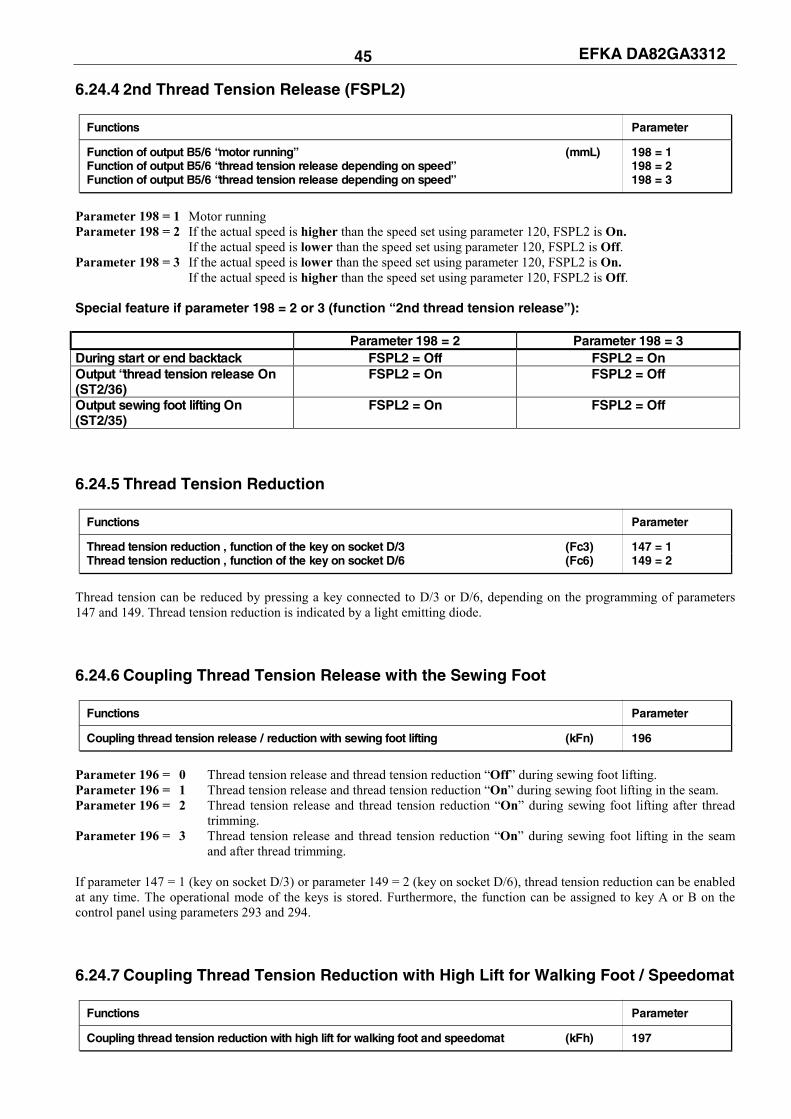
EFKA DA82GA3312 45 6.24.4 2nd Thread Tension Release (FSPL2)
Functions Parameter
Function of output B5/6 “motor running” (mmL) 198 = 1 Function of output B5/6 “thread tension release depending on speed” 198 = 2 Function of output B5/6 “thread tension release depending on speed” 198 = 3
Parameter 198 = 1 Motor running Parameter 198 = 2 If the actual speed is higher than the speed set using parameter 120, FSPL2 is On.
If the actual speed is lower than the speed set using parameter 120, FSPL2 is Off. Parameter 198 = 3 If the actual speed is lower than the speed set using parameter 120, FSPL2 is On.
If the actual speed is higher than the speed set using parameter 120, FSPL2 is Off. Special feature if parameter 198 = 2 or 3 (function “2nd thread tension release”): Parameter 198 = 2 Parameter 198 = 3 During start or end backtack FSPL2 = Off FSPL2 = On Output “thread tension release On (ST2/36)
FSPL2 = On FSPL2 = Off
Output sewing foot lifting On (ST2/35)
FSPL2 = On FSPL2 = Off
6.24.5 Thread Tension Reduction
Functions Parameter
Thread tension reduction , function of the key on socket D/3 (Fc3) 147 = 1 Thread tension reduction , function of the key on socket D/6 (Fc6) 149 = 2
Thread tension can be reduced by pressing a key connected to D/3 or D/6, depending on the programming of parameters 147 and 149. Thread tension reduction is indicated by a light emitting diode. 6.24.6 Coupling Thread Tension Release with the Sewing Foot
Functions Parameter
Coupling thread tension release / reduction with sewing foot lifting (kFn) 196
Parameter 196 = 0 Thread tension release and thread tension reduction “Off” during sewing foot lifting. Parameter 196 = 1 Thread tension release and thread tension reduction “On” during sewing foot lifting in the seam. Parameter 196 = 2 Thread tension release and thread tension reduction “On” during sewing foot lifting after thread
trimming. Parameter 196 = 3 Thread tension release and thread tension reduction “On” during sewing foot lifting in the seam
and after thread trimming. If parameter 147 = 1 (key on socket D/3) or parameter 149 = 2 (key on socket D/6), thread tension reduction can be enabled at any time. The operational mode of the keys is stored. Furthermore, the function can be assigned to key A or B on the control panel using parameters 293 and 294. 6.24.7 Coupling Thread Tension Reduction with High Lift for Walking Foot / Speedomat
Functions Parameter
Coupling thread tension reduction with high lift for walking foot and speedomat (kFh) 197

EFKA DA82GA3312 46 Parameter 197 = 0 Coupling thread tension reduction with high lift for walking foot and speedomat Off. Parameter 197 = 1 Thread tension reduction is disabled and high lift for walking foot enabled using the key on
socket A/7. The speedomat has no effect. Parameter 197 = 2 When reaching high lift walking speed by adjusting the speedomat, thread tension reduction
is disabled. The key on socket A/7 has no effect. Parameter 197 = 3 When reaching high lift walking speed by adjusting the speedomat, thread tension is
disabled. The key on socket A/7 works as with setting 197 = 1. If parameter 197 = 1...3, thread tension reduction can be enabled at any time using the key on socket D/3. 6.25 Seam with Stitch Counting
Functions V820
Stitch counting forward On lefthand arrow above key On Key 2 Stitch counting backward On righthand arrow above key On Stitch counting Off both arrows Off
6.25.1 Number of Stitches for a Seam with Stitch Counting
Functions Parameter
Number of stitches for a seam with stitch counting (Stc) 007 Stitch counting On/Off (StS) 015
The number of stitches for a seam with stitch counting can be programmed and varied using the above parameters directly on the V810/V820 control panel. For fast operator information (HIT) when using the V820 control panel, the value of the function enabled using key 2 can be displayed for approx. 3 seconds. During this time, the value can be varied directly by pressing key + or -. 6.25.2 Stitch Counting Speed
Functions Parameter
Positioning speed (n1) 110 Stitch counting speed (n12) 118 Speed mode for a seam with stitch counting (SGn) 141
Speed control for stitch counting can be selected using parameter 141. Parameter 141 = 0 Execution at pedal controlled speed. Parameter 141 = 1 Execution at fixed speed n12, when pressing the pedal forward (position >1). Parameter 141 = 2 Execution at limited speed n12, when pressing the pedal forward (position >1). Parameter 141 = 3 Automatic execution at fixed speed after having pressed the pedal once. The procedure can be
interrupted by “heelback (-2)". The sewing speed is reduced in each stitch depending on the actual speed (max. 11 stitches before the end of stitch counting), in order to be able to stop exactly at the end of counting. When the light barrier is on, free sewing will be performed after stitch counting. 6.26 Free Seam and Seam with Light Barrier
Functions Parameter
Positioning speed (n1) 110 Upper limit of maximum speed (n2) 111 Limited speed according to setting of 142 (n12) 118 Lower limit of maximum speed (n2_) 121 Speed mode free seam (SFn) 142

EFKA DA82GA3312 47 Speed control for the free seam and the seam with stitch counting can be selected using the speed mode. Parameter 142 = 0 Execution at pedal controlled speed Parameter 142 = 1 Execution at fixed speed n12, when pressing the pedal forward (position >1) Parameter 142 = 2 Execution at limited speed n12, when pressing the pedal forward (position >1) Parameter 141 = 3 Only for the seam with light barrier: - Automatic execution at fixed speed after having pressed the pedal once. - The seam end is initiated by light barrier. - The procedure can be interrupted by heelback (-2). - If the light barrier is not on, speed as with parameter setting 142 = 0. The maximum speed is displayed on the control panel after power On and thread trimming and can be varied directly using key +/-. The setting range lies between the values of parameters 111 and 121. 6.27 Light Barrier Light barrier module LSM001A is provided and is connected to socket B18. Moreover, an external light barrier can be connected to socket A/13. Both light barrier inputs initiate the same function and can be enabled and disabled with the same parameters.
Function on the V810 control panel Parameter
Light barrier On/Off (LS) 009
Functions V820
Light barrier covered/uncovered On righthand arrow above key On Key 3 Light barrier uncovered/covered On lefthand arrow above key On Light barrier Off both arrows Off
6.27.1 Speed after Light Barrier Sensing
Functions Parameter
Speed after light barrier sensing (n5) 114
6.27.2 General Light Barrier Functions
Functions Parameter
Light barrier compensating stitches (for long stitches) (LS) 004 Number of light barrier seams (LSn) 006 Light barrier compensating stitches (for normal stitches) (cLS) 010 Light barrier sensing uncovered/covered (LSd) 131 Start of sewing blocked/unblocked with light barrier uncovered (LSS) 132 Light barrier seam end with thread trimming On/Off (LSE) 133
After sensing the seam end, the compensating stitches are counted at light barrier speed. Suspension of the procedure with pedal in pos. 0 (neutral). Interruption of the procedure with pedal in pos. -2. The thread trimming operation can be disabled using parameter 133, regardless of the setting of key 5 on the V820
control panel. Stop in the basic position. Programming of max. 15 light barrier seams depending on the setting of parameter 006 with stop in the basic position.
Thread trimming after the last light barrier seam. Light barrier sensing uncovered or covered at the seam end can be selected using parameter 131. Start blockage with light barrier uncovered programmable using parameter 132. Speed selection pedal controlled / n5 during the light barrier compensating stitches using parameter 192. The light barrier compensating stitches can be programmed and varied using the above parameters on the V810/V820
control panel. For fast operator information (HIT) when using the V820 control panel, the value of the function enabled using key 3 can be displayed for approx. 3 seconds. During this time, the value can be varied directly by pressing key + or -.

EFKA DA82GA3312 48 6.27.3 Reflection Light Barrier LSM001A Sensitivity setting: Set minimum sensitivity depending on the distance between light barrier and reflection area (turn potentiometer as far as possible to the left). Potentiometer directly on the light barrier module
Mechanical orientation: Orientation is facilitated by a visible light spot on the reflection area. 6.27.4 Automatic Start Controlled by Light Barrier
Functions Parameter
Delay of automatic start (ASd) 128 Automatic start On/Off (ALS) 129 Light barrier sensing uncovered (LSd) 131 Start of sewing blocked with light barrier uncovered (LSS) 132
This function enables an automatic start of the sewing operation as soon as the light barrier senses the insertion of fabric. Prerequisites for the operation: Parameter 009 = ON (light barrier On). Parameter 129 = ON (automatic start On). Parameter 131 = ON (light barrier sensing uncovered). Parameter 132 = ON (no start of sewing with light barrier uncovered). The pedal must be kept pressed forward at the seam end.
For safety reasons this function is enabled only after a normal start of sewing. The light barrier must be covered as long as the pedal is in position 0 (neutral). Then press the pedal forward. This function is disabled when the pedal is no longer pressed forward after the seam end. 6.27.5 Light Barrier Filter for Knitted Fabrics
Functions Parameter
Number of stitches of the light barrier filter (LSF) 005 Light barrier filter On/Off (LSF) 130 Light barrier sensing uncovered or covered (LSd) 131
The filter prevents premature enabling of the light barrier function when sewing knitted fabrics. Enabling/Disabling of the filter using parameter 130 The filter is not active if parameter 005 = 0 Adaptation to the mesh is possible by varying the number of filter stitches. Knitted fabric sensing with light barrier uncovered covered, if parameter 131 = OFF
Knitted fabric sensing with light barrier covered uncovered, of parameter 131 = ON 6.28 Needle Up/Down / Single Stitch The needle up/down or single stitch function can be activated using the keys on two different inputs and selected using separate parameters.
Mode for the key connected to connector A/6
Functions Parameter
Functions of the key on socket A/6 (nh1) 140 Functions of the key on socket D/1 (nh2) 144 1 = Needle up 2 = Needle up/down 3 = Single stitch 4 = Single stitch with stitch length switching (normal stitch length) 5 = Needle up if outside position 2 or reverse position 6 = Machine stop in position 2

EFKA DA82GA3312 49 Parameter 140/144 = 1: Needle up When the key is pressed, the drive runs from position 1 to the reverse position. This does not depend on whether reverse motor rotation is On or Off. If parameter 180 is set to 0, the drive stops in position 2. If the drive is outside the slot position 1, it does not move for safety reasons. The function is blocked after power On until sewing is started.
Parameter 140/144 = 2: Needle up/down When the key is pressed, the drive runs from position 1 to the reverse position or from the reverse position to position 1. This does not depend on whether reverse motor rotation is On or Off. If parameter 180 is set to 0, the drive stops in position 2. If the drive is outside the slot between position 1 and 1A or position 2 and 2A, it runs to the next possible position. After power On, the drive runs to the next position identified.
Parameter 140/144 = 3: Single stitch When the key is pressed, the drive performs one rotation from position 1 to position 1. If the drive is in the reverse position, it runs to position 1 when pressing the key and from position 1 to position 1 each time the key is pressed again.
Parameter 140/144 = 4: Single stitch with normal stitch length When the key is pressed, the drive performs one rotation from position 1 to position 1. If the drive is in the reverse position, it runs to position 1 when pressing the key and from position 1 to position 1 each time the key is pressed again. At the same time, the output “switch stitch length” on socket A/30 is enabled and the corresponding light emitting diode on socket A/29 disabled.
Parameter 140/144 = 5: Needle in position 2 When the key is pressed, the drive runs to position 2 or reverse position, independently of its present position. This function is also possible after power On.
Parameter 140/144 = 6: Machine stop in position 2 After the key has been pressed, the drive stops in position 2 and the sewing foot is lifted. The machine run blockage symbol blinks on the V820 and “stop” on the V810, respectively. The drive functions are blocked. Only after power Off/On is the drive again ready for operation. 6.29 F1/F2 Function Key Assignment on the V810/V820 Control Panels
Functions Parameter
Selection of input function on key (A) "F1" on the V810/V820 control panels (tF1) 293 Selection of input function on key (B) "F2" on the V810/V820 control panels (tF2) 294
The following functions are possible using parameters 293 and 294: 293/294 = 0 Input function blocked 293/294 = 1 Needle up: Function according to setting of parameter 140 or 144. 293/294 = 2 Needle up-down: Function according to setting of parameter 140 or 144. 293/294 = 3 Single stitch (basting stitch): Function according to setting of parameter 140 or 144. 293/294 = 4 Single stitch with normal stitch length: Function according to setting of parameter 140 or 144. 293/294 = 5 Needle to position 2: Function according to setting of parameter 140 or 144. 293/294 = 6 Switch stitch length: Normal or long stitch. 293/294 = 7 Thread tension: Function for thread tension reduction. 293/294 = 8 Sewing foot pressure: Function for sewing foot pressure reduction. 293/294 = 9 Roller: Lift or lower. 293/294 = 10 Speed limitation DB3000. 293/294 = 11/12 No function 293/294 = 13 High lift for walking foot operational mode not stored/stored according to setting of parameter 138: The signal “high lift for walking foot” is issued as long as the key is pressed down, and the drive runs with speed limitation (n10). 293/294 = 14/15 No function 293/294 = 16 Intermediate backtack: Upon pressing the key, the backtack will be enabled anywhere in the seam and at standstill of the drive. 293/294 = 17 Backtack suppression / recall: Upon pressing the key, the backtack will be suppressed or recalled once. 293/294 = 18 Coupling the sewing foot with thread tension release: This function can be enabled or disabled according to the setting of parameter 196. 293/294 = 19 Reset thread monitor: After inserting a full bobbin, the stitch counter is set to the value determined using parameter 085.
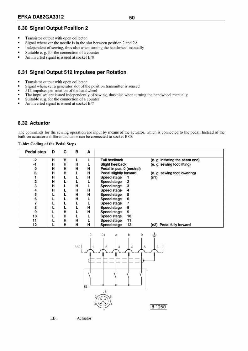
EFKA DA82GA3312 50 6.30 Signal Output Position 2 Transistor output with open collector Signal whenever the needle is in the slot between position 2 and 2A Independent of sewing, thus also when turning the handwheel manually Suitable e. g. for the connection of a counter An inverted signal is issued at socket B/8
6.31 Signal Output 512 Impulses per Rotation Transistor output with open collector Signal whenever a generator slot of the position transmitter is sensed 512 impulses per rotation of the handwheel The impulses are issued independently of sewing, thus also when turning the handwheel manually Suitable e. g. for the connection of a counter An inverted signal is issued at socket B/7
6.32 Actuator The commands for the sewing operation are input by means of the actuator, which is connected to the pedal. Instead of the built-on actuator a different actuator can be connected to socket B80.
Table: Coding of the Pedal Steps
Pedal step D C B A
-2 H H L L Full heelback (e. g. initiating the seam end) -1 H H H L Slight heelback (e. g. sewing foot lifting) 0 H H H H Pedal in pos. 0 (neutral) ½ H H L H Pedal slightly forward (e. g. sewing foot lowering) 1 H L L H Speed stage 1 (n1) 2 H L L L Speed stage 2 3 H L H L Speed stage 3 4 H L H H Speed stage 4 5 L L H H Speed stage 5 6 L L H L Speed stage 6 7 L L L L Speed stage 7 8 L L L H Speed stage 8 9 L H L H Speed stage 9 10 L H L L Speed stage 10 11 L H H L Speed stage 11 12 L H H H Speed stage 12 (n2) Pedal fully forward
EB.. Actuator
EFKA DA82GA3312 51
Functions Parameter
Speed stage graduation (nSt) 119
The pedal characteristics (speed change from stage to stage) can be varied. Possible characteristic curves: - linear - progressive - highly progressive 6.33 Acoustic Signal
Functions Parameter
Acoustic signal when machine run blockage or thread monitor is On (AkS) 127
An acoustic signal which sounds in the following cases can be enabled using parameter 127: Parameter 127 = 0 Acoustic signal Off. Parameter 127 = 1 Acoustic signal from stop after execution of the stitches to pressing key 8. Parameter 127 = 2 The drive stops after execution of the stitches. Sewing is possible up to the seam end. Then
the acoustic signal sounds until key 8 is pressed. Parameter 127 = 3 The drive stops after execution of the stitches, and the acoustic signal sounds 5 times. Sewing
is possible up to the seam end. Then the acoustic signal sounds until key 8 is pressed. 6.34 Master Reset
Recovery of factory settings. Press the "P" key and turn power on Input code number "190" Press the "E" key Parameter 100 appears on the display Press the "E" key The parameter value is shown on the display Set to "170" using the “+” key Press the "P" key twice Turn power off Turn power on. All parameters, except 111, 161, 170, 171, 190...194, have been reset to their factory settings.

EFKA DA82GA3312 52 7 Input and Output Function Test
Functions Parameter
Input and output test (Sr4) 173
Function test of external inputs and transistor power outputs with connected actuators (e.g. solenoids and solenoid valves). 7.1 Function Test with the V810/V820 Control Panel Output test: Select parameter 173 Select the desired output by means of the +/- keys Enable the selected output by means of the >> key on the V810 or the incorporated control panel Enable the selected output by means of the B key (bottom right) on the V820
Display Assignment of the Outputs Socket / Pin 01 Backtacking on socket A/34 02 Sewing foot lifting on socket A/35 03 Thread trimmer on socket A/37 04 Thread wiper on socket A/27 05 Switch stitch length on socket A/30 06 Thread tension release on socket A/36, B/5, C/5 07 Thread tension reduction on socket A/20 08 Needle cooling on socket A/28 09 Motor running on socket A/26, B/6 10 High lift for walking foot on socket A/32 11 Not assigned on socket A/22 12 LED for needle up/down on socket D/9 13 LED for long stitch on socket D/10 14 Thread clamp on socket A/18 15 LED for high lift limitation on socket A/31 16 LED for righthand thread monitor on socket A/25 17 LED for sewing foot pressure reduction on socket D/12 18 LED for thread tension reduction / on socket D/11 backtack suppression/recall 19 Sewing foot pressure reduction on socket A/21 20 LED for lefthand thread monitor on socket A/23 21 Flip-flop on socket C/6 22 LED high lift limitation/ thread tension reduction on socket D/14 23 LED backtack suppression/recall on socket A/24 24 LED speed limitation DB3000/intermediate backtack on socket D/13 25 LED for long stitch on socket A/29 26 Not assigned on socket A/17 27 Not assigned on socket A/16 28 Roller feed on socket A/15
Input test: Press the – key several times until "OFF" or "ON" appears on the control display. Actuation of external switches is displayed by the switching state ON/OFF. Several switches must not be closed at the same time.
The letter symbols in parentheses ( ) are visible only if the V820 control panel is connected!

EFKA DA82GA3312 53 8 Error Displays
General Information
On the V810 On the V820 Signification
InF A1 InF A1 Pedal not in neutral position, when turning the machine on
-StoP- blinking Symbol blinking Machine run blockage
InF A3 InF A3 The position to which all position values refer has not been stored (reference position missing)
InF A5 InF A5 Emergency run, identification of an invalid machine select
Programming Functions and Values (Parameters)
On the V810 On the V820 Signification
Returns to the Like V810 + Wrong code number or parameter number input first digit display InF F1
Serious Condition
On the V810 On the V820 Signification
InF E1 InF E1 After power On, position transmitter or commutation transmitter defective or connecting cables have been changed by mistake. During machine run or after a sewing operation, only position transmitter defects can be identified.
InF E2 InF E2 Line voltage too low, or time between power off and power on too short.
InF E3 InF E3 Machine blocked or does not reach the desired speed.
InF E4 InF E4 Control disturbed by deficient grounding or loose contact.
Hardware Disturbance
On the V810 On the V820 Signification
InF H1 InF H1 Commutation transmitter cord or frequency converter disturbed.
InF H2 InF H2 Processor disturbed

EFKA DA82GA3312 54
9 Operating Elements of the V810 Control Panel
P
+
A1 2 3 4
variocontrol 810
KL2185B
-
1
E
The V810 control panel is supplied with slide-in strip no. 1 above the keys. For different functions the strip can be replaced with a different one supplied with the control panel. Set parameter 291 in this case. See also V810 / V820 instruction manual!
Function Key Assignment Key P = Call or exit of programming mode Key E = Enter key for modifications in the programming mode Key + = Increase of the value indicated in the programming mode Key - = Decrease of the value indicated in the programming mode Key 1 = Start backtack SINGLE / DOUBLE / OFF Key 2 = End backtack SINGLE / DOUBLE / OFF Key 3 = Automatic sewing foot lift after thread trimming ON / OFF Automatic sewing foot lift at stop in the seam ON / OFF Key 4 = Basic position needle down (POSITION 1) / needle up (POSITION 2) Key A= Key for backtack suppression/recall (Different input functions can be assigned to key A using parameter 293) Key B= Key for needle up or shift key in the programming mode (Different input functions can be assigned to key B using parameter 294)

EFKA DA82GA3312 55 10 Operating Elements of the V820 Control Panel
variocontrol 820
P E
KL2186
41 2 3
B
R
85 6 7 9 0
A
+ -
F 1
The V820 control panel is supplied with slide-in strip no. 1 above the keys.
Function Key Assignment Key P = Call or exit of programming mode Key E = Enter key for modifications in the programming mode Key + = Increase of the value indicated in the programming mode Key - = Decrease of the value indicated in the programming mode Key 1 = Start backtack SINGLE / DOUBLE / OFF Key 2 = Stitch counting seam FORWARD / BACKWARD / OFF Key 3 = Light barrier function COVERED-UNCOVERED / UNCOVERED-COVERED / OFF Key 4 = End backtack SINGLE / DOUBLE / OFF Key 5 = THREAD TRIMMER / THREAD TRIMMER + THREAD WIPER / OFF Key 6 = Automatic sewing foot lift after thread trimming ON / OFF Automatic sewing foot lift at stop in the seam ON / OFF Key 7 = Basic position needle down (POSITION 1) / needle up (POSITION 2) Key 8 = Thread monitor ON / OFF (>1 sec) or reset (<1 sec) Key 9 = Function key, programmable Key 0 = Teach-in / execution of 40 possible seam sections Key A = Key for backtack suppression/recall (Different input functions can be assigned to key A using parameter 293) Key B = Key for needle up or shift key in the programming mode (Different input functions can be assigned to key B using parameter 294)
Special Key Assignment for HIT After having pressed key 1, 2, 3, 4 or 9, the following can be varied using key +/-: Key 1= Number of stitches of the selected start backtack Key 2= Number of stitches of the seam with stitch counting Key 3= Number of light barrier compensating stitches Key 4= Number of stitches of the selected end backtack Key 9 = Number of stitches or On/Off of the programmed function

FRANKL & KIRCHNER GMBH & CO KG SCHEFFELSTRASSE 73 – 68723 SCHWETZINGEN – GERMANY PHONE: +49-6202-2020 – FAX: +49-6202-202115 E-mail: [email protected] – http://www.efka.net
OF AMERICA INC. 3715 NORTHCREST ROAD – SUITE 10 – ATLANTA – GEORGIA 30340 PHONE: +1 (770) 457-7006 – FAX: +1 (770) 458-3899 – E-mail: [email protected]
ELECTRONIC MOTORS SINGAPORE PTE. LTD. 67, AYER RAJAH CRESCENT 05-03 – SINGAPORE 139950 PHONE: +65-67772459 – FAX: +65-67771048 – E-mail: [email protected] 4(5)-160605 H (402275 EN)