CDC IT Directions CDC Project Management Summit Jim Seligman CDC Chief Information Officer.

CONTROL DATA" 3200 Computer system / ~ e a l Time Applications

At this precise moment, events in science
and industry are occurring which demand
solutions and control. Among these events-
in-real-time are many that directly affect your
field . . . in the aerospace industry, bio-medi-
cal research, industrial control, military, nu-
clear research, and others.
To provide the high-speed data handling re-
quired for solution and control of events in
real time, the CONTROL DATA 3200 can be
expected to function both as an immediate
and long range answer. . . immediate be-
cause its big-computer capability is ready for
delivery at a medium-range price now; long-
range because its modular design permits
steady expansion against problem growth.
As you examine the CONTROL DATA 3200
Computer System in these pages, you will
note an ideal system design for real-time
operations. . . modular, expandable input1
output communications system, core-to-core
transfer capability between computers, a
broad instruction repertoire to facilitate high-
speed data handling.
You will discover something else also . . . "user selectivity", an important advantage
that allows you to put into operation the most
efficient CONTROL DATA 3200 Computer
System for your immediate and long range
application.


. The CONTROL DATA@ 3200 Computer System.. Characterized for Real-Time Applications
24-bit word length plus 4 parity bits
Magnetic core storage: 4,096; 8,192; 16,384; or 32,768 words
Storage cycle time - 1.25 microseconds Access time - 750 nanoseconds
True Storage bank overlap
Hi-speed Register File Storage Capacity. . . . . . . . . . . . . . . . . . . . . . .64 words Total cycle t ime. . . . . . . . . . . . . . . . . . 5 0 0 nanoseconds Access t ime . . . . . . . . . . . . . . . . . . 250 nanoseconds
Bi-directional communication channels 1,2,4, 6 or 8 communication channels with direct access to core storage al l communication channels completely buffered
Parity checking on core storage and input/output
Input/Output Transfer rate on normal channels (12-bit) one mill ion characters (6 bits each) per second
24-bit channels available as standard options for larger data movement
For special applications, I /O may take place directly with storage at a rate of one 24-bit word per storage cycle (1.25 ,MS.)
Three 15-bit Index Registers
6 4 external interrupt lines 8 interrupt lines per communication channel built-in priority program accessible mask register
96 External Sense Lines 12 sense lines per communication channel
Power Loss Protection Register Protection in case of power failure
Real-Time Clock (Program Selectable)
Inter-Computer Transfer Core to core buffered block data transfer between computers
Intra-Computer Transfer Buffered Block data transfer i n magnetic core
Computer Satellite Ability 3200 to 3200 3200 to 3600
Instruction Repertoire includes: Fixed and Floating Point Arithmetic 24 and 48-bit arithmetic Logical and Masking operations Storage Search 6-bit BCD character arithmetic and data handling "Pause" for ultra-hi-speed I / O communication Multi-level indirect and indexed address modification Inter-Register transfer Block Search and Move (Buffered)
Execution Times Fixed Point Add (24-bits) 2.5 ps. Floating Point Add (48-bits) 12.0 ps. Fixed Point Multiply (24-bits) 8.8 to 12.0 ps. Floating Point Multiply (48-bits) 29.0 ps.
l n p u t l ~ u t p u f Equipment IN
Punched Cards 1200/min. Magnetic Tape 15-120 K C Paper Tape 350 cps. Printer
OUT 250lmin.
15-120 K C 110 cps.
300-1000 Ipm.
(Also available: magnetic drum and disk file storage, AID-DIA converters, line plotters, digital data terminals, and special interface equipment)
Computer Console Keyboard entry Register display
Storage Protection Protects designated sections of storage from uninten- tional destructive writing
Buffered Arithmetic Section Multiply and divide instructions continue concurrently with any instructions not using the arithmetic unit, such as Input/Output control
3200 circuit modules developed for and proved on Control Data's 3600 large-scale computer
I CONTROL DATA 166 Line Printer Magnetic Tape Transport 4
CONTROL DATA 405 Card Reader


3200 REAL-TIME PROGRAMMING SYSTEMS
Complete software systems for the 3200
Real-Time Compute'r are developed and, by thorough study, are pre-planned in a manner allowing you to operate all systems as a group or each system individually.
Included are a complete Monitor Operating System (SCOPE 32), a Symbolic Assembler (COMPASS 32) and a FORTRAN Compiler (FORTRAN 32). In profile . . .
SCOPE 32 (Monitor) . . . automatically moni- tors and controls the compilation and execu- tion of programs written in various source languages. Among its advantages SCOPE provides:
Job Stacking Programs written in different languages can be compiled and executed without operator intervention.
Job Accounting Each job is automatically logged as it is processed, giv- ing the user control over project time allocation and maximum computer utilization.
Automatic storage allocation
Assignment of inputloutput functions and initiation of all I10 activities
Instructions to the operator through printed messages
COMPASS 32 (Symbolic Assembler) . . . Control Data's comprehensive assembly system per- mits the user to write machine language pro- grams using symbolic instructions. Input to the assembler may be from cards, paper tape, or magnetic tape. The assembler out- put is a machine code, relocatable binary object program.
Some COMPASS advantages:
Different types of data may be defined
Macros can be defined by the programmer
Arithmetic expressions can be used in address fields
FORTRAN 32 . . . FORTRAN for Control Data's 3200 Computer System takes full advan- tage of both the latest compiler techniques through the sophisticated 3200 hardware. Control Data FORTRAN compilers are nota- ble for their extremely fast compilation and execution speeds. For example, the 3200's
ability to perform character operations re- sults in faster FORTRAN compilation. The 3200 does a character search directly rather than through a repeated instruction loop. The high-speed Register File is used to store ID List parameters during compilation which eliminates the need for special protective measures to prevent inadvertent destruction of the parameters. The result is faster, sim- pler storage allocation.
FORTRAN recompiling is not necessary when the 3200 system is expanded to in- clude optional arithmetic. FORTRAN com- piles all floating point source coding to float- ing point machine code. If the computer d ~ e s not have floating point hardware, these in- structions are automatically trapped and executed by floating point subroutines.
All of the above systems operate on a stand- ard 3200 system including five inputloutput devices and 8,+192 words of storage. For lesser systems with two inputloutput devices and 4,096 words of storage, a separate stor- age package is available which includes FORTRAN II and a basic assembly system.
USER SELECTIVITY
A most significant feature for real-time use of the Control Data 3200 Computer System is system selection at the most important level . . . the user.
Modularity, as it is now defined by the 3200, puts in your hands the opportunity of select- ing exact system power against your indi- vidual problem through Control data's new "broad-line" equipment options.
If need be, only those system features valu- able to the solution of your distinct real-time application may be used to broaden the basic 3200 System. Available now for selection or for field installation later are:
Floating Point Arithmetic Hardware
BCD Arithmetic Hardware
Additional Core Storage
Multiple InputIOutput Communication Channels with 6, 12, or 24-bit parallel data transfer
Additional "Arithmetic and Control" Processor Modules
Stand-up or desk-sized consoles
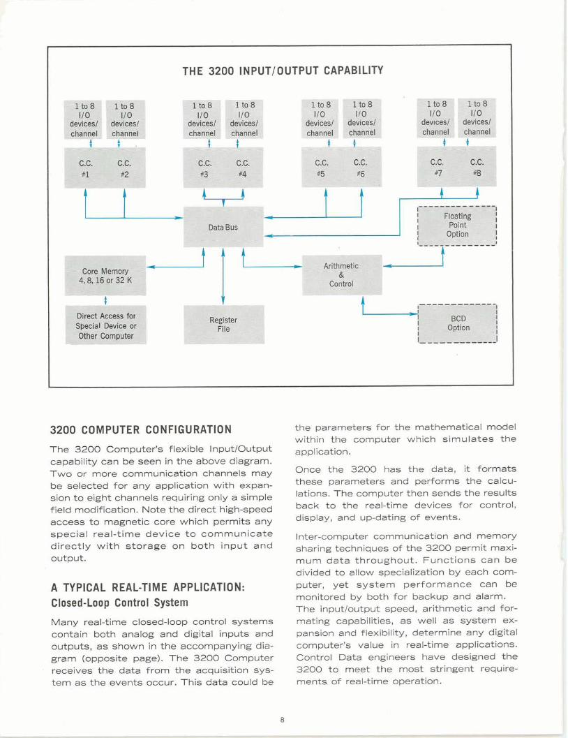
THE 3200 INPUTIOUTPUT CAPABILITY
3200 COMPUTER CONFIGURATION
The 3200 Computer's flexible InputIOutput capability can be seen in the above diagram. Two or more communication channels may be selected for any application with expan- sion to eight channels requiring only a simple field modification. Note the direct high-speed access to magnetic core which permits any special real-time device t o communicate directly with storage on both input and output.
A TYPICAL REAL-TIME APPLICATION: Closed-Loop Control System
Many real-time closed-loop control systems contain both analog and digital inputs and outputs, as shown in the accompanying dia- gram (opposite page). The 3200 Computer receives the data from the acquisition sys- tem as the events occur. This data could be
the parameters for the mathematical model within the computer which simulates the application.
Once the 3200 has the data, it formats these parameters and performs the calcu- lations. The computer then sends the results back to the real-time devices for control, display, and up-dating of events.
Inter-computer communication and memory sharing techniques of the 3200 permit maxi- mum data throughout. Functions can be divided to allow specialization by each com- puter, yet system performance can be monitored by both for backup and alarm. The inputloutput speed, arithmetic and for- mating capabilities, as well as system ex-pansion and flexibility, determine any digital computer's value in real-time applications. Control Data engineers have designed the 3200 to meet the most stringent require- ments of real-time operation.

3200 EXPANDED COMPUTER I N A REAL-TIME CLOSED-LOOP APPLICATION
Numbers 1through 8 above are bi-directional data channels. The unused data channels are normally connected to such peripheral equipments as magnetic tape units, line printers, plotters, displays, etc. to represent a complete real-time computer system.

CONTROL DATA SALES OFFICES ALBUQUERQUE. BEVERLY HILLS. BIRMINGHAM BOSTON
CHICAGO. CLEVELAND. COCOA BEACH DALLAS. DAYTON
DENVER DETROIT. HONOLULU .HOUSTON
HUNTSVILLE. ITHACA KANSAS CITY, KAN. LOS ALTOS. MINNEAPOLIS. NEWARK
NEW YORK CITY OMAHA PAL0 ALTO. PHILADELPHIA PITTSBURGH
SAN DIEGO SAN FRANCISCO SEATTLE WASHINGTON, D.C.
INTERNATIONAL OFFICES BAD HOMBURG, GERMANY. MELBOURNE, AUSTRALIA LUCERNE, SWITZERLAND
STOCKHOLM, SWEDEN .ZURICH, SWITZERLAND. PARIS, FRANCE. OSLO, NORWAY
Pub. No. Br. 23 (10-63)