Control Coordination Within a VSC HVDC Link for Power ... · 1 Control Coordination Within a VSC...
10
1 Control Coordination Within a VSC HVDC Link for Power Oscillation Damping: A Robust Decentralized Approach Using Homotopy Yousef Pipelzadeh, Student Member, IEEE, Balarko Chaudhuri, Senior Member, IEEE, Tim C. Green, Senior Member, IEEE Abstract—Power oscillations can be damped effectively through modulation of both active and reactive power of a voltage source converter (VSC) based high voltage direct current (HVDC) link. The challenge, however, is how to coordinate the control action properly at the two ends of the link without using a centralized control scheme which require fast communication of control signals to remote actuator (converters) sites. A full centralized controller may result in a closed-loop performance worse than open-loop in case of a communication loss of feedback signal(s). Alternatively, with block-diagonal control structure, the individual control loops are decoupled from each other which are not only easier to implement in a decentralized way but also shown to guarantee a certain level of performance. Here the concept of homotopy is applied to obtain a single block-diagonal controller from a set of full controllers, individually designed to ensure specified closed-loop performance for a set of operating conditions. Simulation studies in DIgSILENT PowerFactory are carried out on two test systems to demonstrate both robustness and control coordination in a decentralized framework. Index Terms—HVDC, VSC, Stability, Damping, Decentralized Control, Linear Matrix Inequalities (LMI), Bilinear Matrix Inequalities (BMI), System Identification, Modal Residues, RGA I. I NTRODUCTION S UPPLEMENTARY modulation of active power through an high voltage direct current (HVDC) link to improve damping of low frequency power oscillations in host AC networks has been exercised by network operators like WECC since the 1970s [1]. With an increasing number of HVDC installations around the world, especially in countries with long transmission corridors like Brazil, China and India, there has been a renewed interest in this area [2], [3], [4]. In the U.K., the transfer capacity from Scotland to England needs to increase significantly to secure the growing demand in the south with the wind penetration in the north. Two sub-sea HVDC links, each rated at around 2 GW are planned along the east and west coasts [5] to add capacity and also enhance the stability limit of the existing Scottish-English inter-connector. The western link, which is currently under development is based on current source converter (CSC) technology with a planned completion date of 2015, while the one running along Support from the EPSRC UK under grant EP/F037686 (Power Networks Research Academy) is gratefully acknowledged. The authors are with the Control and Power Research group, Imperial College, London, United Kingdom. e-mail:{y.pipelzadeh08, b.chaudhuri, t.green}@imperial.ac.uk the east coast is likely to be of voltage source converter (VSC) technology [6], with an anticipated completion date of 2018. Most of the work on HVDC control to damp oscillations, including [2], [3], [4], have primarily focused on HVDC networks based on CSC technology. A VSC HVDC link allows independent modulation of active power and reactive power (at both ends) and hence offers more flexibility than CSC where only the active power can be modulated. There is tremendous potential for VSC HVDC systems to contribute towards improvement in AC system dynamic performance as discussed in [7], [8], [9]. The challenge, however, is to coordinate the supplementary control action properly at the two ends of the link without the use of centralized control, which requires fast communication of control signals to remote actuator (converters) sites. Of course wide area measurement systems (WAMS) are needed to communicate phasor measurement units (PMU) signals to the control centers. A sequential loop-closure strategy for multiple flexible ac transmission systems (FACTS) whereby each control loop is designed independently was introduced in [10]. Such a sequential design does not take into account the presence of all the control inputs simultaneously, thus proper coordination and allocation of control effort among all available control inputs is not addressed in a systematic way. In this work, coordinated supplementary control of the real and reactive power reference of the rectifier side VSC HVDC converter and the reactive power reference of the inverter side VSC HVDC converter is proposed. The idea is to ensure appropriate sharing of the overall control duty and thus lessen the burden on each. One way to achieve coordinated control is to design all the control loops simultaneously in a multi- variable framework. However, the resulting full multi-input, multi-output (MIMO) controller is difficult to implement in a decentralized (control center located at the actuator site) way as it requires all the feedback signals, some or all of which could be from remote locations, to be transmitted to each actuator location. Moreover, because of the cross-coupling between the control loops through the off-diagonal terms of the controller, the closed-loop performance could be potentially worse than open-loop in case of loss of one or more remote feedback signal(s). On the other hand, if the control structure is block-diagonal, the individual control loops are decoupled from each other which is not only simpler to implement in a decentralized way but also guarantees a minimum level of performance through the healthy control loops in the event of
Transcript of Control Coordination Within a VSC HVDC Link for Power ... · 1 Control Coordination Within a VSC...
1
Control Coordination Within a VSC HVDC Linkfor Power Oscillation Damping: A RobustDecentralized Approach Using Homotopy
Yousef Pipelzadeh,Student Member, IEEE,Balarko Chaudhuri,Senior Member, IEEE,Tim C. Green,SeniorMember, IEEE
Abstract—Power oscillations can be damped effectivelythrough modulation of both active and reactive power of a voltagesource converter (VSC) based high voltage direct current (HVDC)link. The challenge, however, is how to coordinate the controlaction properly at the two ends of the link without using acentralized control scheme which require fast communicationof control signals to remote actuator (converters) sites. Afullcentralized controller may result in a closed-loop performanceworse than open-loop in case of a communication loss of feedbacksignal(s). Alternatively, with block-diagonal control structure, theindividual control loops are decoupled from each other whichare not only easier to implement in a decentralized way but alsoshown to guarantee a certain level of performance. Here theconcept of homotopy is applied to obtain a single block-diagonalcontroller from a set of full controllers, individually des igned toensure specified closed-loop performance for a set of operatingconditions. Simulation studies in DIgSILENT PowerFactory arecarried out on two test systems to demonstrate both robustnessand control coordination in a decentralized framework.
Index Terms—HVDC, VSC, Stability, Damping, DecentralizedControl, Linear Matrix Inequalities (LMI), Bilinear Matri xInequalities (BMI), System Identification, Modal Residues, RGA
I. I NTRODUCTION
SUPPLEMENTARY modulation of active power throughan high voltage direct current (HVDC) link to improve
damping of low frequency power oscillations in host ACnetworks has been exercised by network operators like WECCsince the 1970s [1]. With an increasing number of HVDCinstallations around the world, especially in countries withlong transmission corridors like Brazil, China and India, therehas been a renewed interest in this area [2], [3], [4].
In the U.K., the transfer capacity from Scotland to Englandneeds to increase significantly to secure the growing demandinthe south with the wind penetration in the north. Two sub-seaHVDC links, each rated at around 2 GW are planned along theeast and west coasts [5] to add capacity and also enhance thestability limit of the existing Scottish-English inter-connector.The western link, which is currently under development isbased on current source converter (CSC) technology with aplanned completion date of 2015, while the one running along
Support from the EPSRC UK under grant EP/F037686 (Power NetworksResearch Academy) is gratefully acknowledged.
The authors are with the Control and Power Research group, ImperialCollege, London, United Kingdom.e-mail:{y.pipelzadeh08, b.chaudhuri, t.green}@imperial.ac.uk
the east coast is likely to be of voltage source converter (VSC)technology [6], with an anticipated completion date of 2018.
Most of the work on HVDC control to damp oscillations,including [2], [3], [4], have primarily focused on HVDCnetworks based on CSC technology. A VSC HVDC link allowsindependent modulation of active power and reactive power(at both ends) and hence offers more flexibility than CSCwhere only the active power can be modulated. There istremendous potential for VSC HVDC systems to contributetowards improvement in AC system dynamic performance asdiscussed in [7], [8], [9].
The challenge, however, is to coordinate the supplementarycontrol action properly at the two ends of the link without theuse of centralized control, which requires fast communicationof control signals to remote actuator (converters) sites. Ofcourse wide area measurement systems (WAMS) are neededto communicate phasor measurement units (PMU) signals tothe control centers. A sequential loop-closure strategy formultiple flexible ac transmission systems (FACTS) wherebyeach control loop is designed independently was introducedin [10]. Such a sequential design does not take into accountthe presence of all the control inputs simultaneously, thusproper coordination and allocation of control effort amongallavailable control inputs is not addressed in a systematic way.
In this work, coordinated supplementary control of the realand reactive power reference of the rectifier side VSC HVDCconverter and the reactive power reference of the inverter sideVSC HVDC converter is proposed. The idea is to ensureappropriate sharing of the overall control duty and thus lessenthe burden on each. One way to achieve coordinated controlis to design all the control loops simultaneously in a multi-variable framework. However, the resulting full multi-input,multi-output (MIMO) controller is difficult to implement inadecentralized (control center located at the actuator site) wayas it requires all the feedback signals, some or all of whichcould be from remote locations, to be transmitted to eachactuator location. Moreover, because of the cross-couplingbetween the control loops through the off-diagonal terms ofthecontroller, the closed-loop performance could be potentiallyworse than open-loop in case of loss of one or more remotefeedback signal(s). On the other hand, if the control structureis block-diagonal, the individual control loops are decoupledfrom each other which is not only simpler to implement ina decentralized way but also guarantees a minimum level ofperformance through the healthy control loops in the event of

2
loss of one or more (but not all) remote feedback signals.Of course, the controller is required to be robust for a range
of operating conditions. A procedure based on H∞ is discussedin [11] for tuning multiple FACTS devices. In [12], a dynamicoutput feedback for decentralized design using linear matrixinequality (LMIs) considering multiple operating conditions isillustrated. The controller order, however, is the same as thedimension of the open-loop plant for both these approacheswhich could be prohibitively large for practical implemen-tation. An analytical design formulation using homotopy isintroduced in [13], where a full MIMO controller can bedeformed into a block diagonal structure resulting in a setof low order single-input, single-output (SISO) decentralizedcontrollers. This approach was applied in controlling structuralvibrations during large disturbances such as earthquakes [14].
In this paper, our main research question is: Can a setof decentralized, robust SISO controllers be designed forsupplementary control at the two ends of a VSC HVDC linkembedded within a power system such that the control actionis coordinated and a minimum performance level is guaranteedin the event of loss of a remote feedback signal?.
To address this, first a MIMO controller is designed in LMIframework to achieve coordination amongst the modulation ofactive and reactive power at either end of the VSC HVDC link.An extension to the standard homotopy framework is proposed[13] such that a single block-diagonal decentralized controlleris obtained from a set of full centralized controllers, individ-ually designed to ensure specified closed-loop performancefor a set of operating conditions. Thus both robustness andcontrol coordination is achieved simultaneously in a decentral-ized framework without the need for fast communication ofcontrol signals to remote actuator (converters) sites. Theterms‘decentralized’and ‘block-diagonal’are used interchangeablythroughout the rest of the paper.
II. ROBUST DECENTRALIZED CONTROL: HOMOTOPY
APPROACH
The control design is formulated in two-stages. In thefirst stage, a centralized controller,GC (s) is computed usingmethods reported in [12], [15], [16]. In the second stage, thecontroller matrices are deformed from full matrices definedbya centralized controller, as shown in Fig. 1(a) to block diagonalmatrices which describes a decentralized control structure,GD(s), as shown in Fig. 1(b).
-
r yu
(b)
-
r yu
(a)
Fig. 1. Closed loop system with (a) full centralized controller and (b) block-diagonal decentralized controller.
A. Design of Centralized Damping Controller
Consider a linearized system modelGi(s) expressed instate-space form as:
Gi(s) ,
[Ai Bi
Ci 0
]
(1)
A ∈ <n×n, B ∈ <n×m, C ∈ <m×n
Wherei represents theith operating condition. The objectiveis to synthesize a full-order centralized linear output feedbackcontrollerGCi
(s) using [15], where:
GCi(s) ,
[Aki
Bki
Cki0
]
(2)
Ak ∈ <n×n, Bk ∈ <n×m, Ck ∈ <m×n
The closed loop system is synthesized by feedback connec-tion of (1) & (2) represented byx = Aix.
where, ˙x ∈ <2n corresponds to the combined state vectorof both the plant and the controller. The closed loop transferfunction is given byT (s) = Ci(sI − Ai)Bi + Di with theclosed loop system matricesAi, Bi, Ci, Di given by:
[Ai Bi
Ci Di
]
=
Ai BiCkiBi
BkiCi Aki
0Ci 0 0
(3)
Without any loss of generality, it can be assumed that thedirect transmission termD can be neglected as it does notinfluence the mode. The criterion of stabilizing system (1) bythe centralized controller (2) is subject to findingAki
, Bki, Cki
and Pi > 0, subject to satisfying the inequality:
AiPi + PiAi
T< 0 (4)
However, satisfying the inequality in (4), will only guaranteestability. i.e. the poles located in the left half plane. In powersystem applications, its a requirement that power oscillationssettle within 10 – 15 s [17]. This can be achieved if the closed-loop poles corresponding to the critical poles have a minimumdamping ratio.
Minimum Damping Performance: A customary way to en-sure satisfactory closed-loop transients is to place the closed-loop poles in a suitable region of the complex plane. Thisapproach is referred to as regional pole-placements, wherethe closed-loop poles are assigned to specific locations in thecomplex plane. This is formulated in terms of LMI regionsbased on a ‘conic sector’ which is appropriate for powersystem damping control applications as it defines a minimumdamping for the closed loop dominant inter-area modes[18].
The closed-loop system is guaranteed to have all its polesin the conic sector with apex at the origin and internal angleθ if and only if there exists a symmetric matrixPi > 0 suchthat:
[
sin θ(AiPi + PiAi
T) cos θ(AiPi − PiAi
T)
cos θ(PiAi
T− AiPi) sin θ(AiPi + PiAi
T)
]
< 0 (5)
The inequality in (5) contains the productAP which arefunctions of the controller parametersAk, Bk, Ck and the con-troller parameters themselves are function ofP . This leads to

3
AP becoming non-linear inP . Following the practice outlinedin [15], it is possible to linearize the problem through changeof controller variables. The resulting centralized controller isobtained asGci
(s) = Cki(sI−Aki)−1Bki. The damping ratio
of all the poles lying inside the sector is guaranteed to haveminimum damping ratioζ = cosϑ.
Remark 1.1:The order of the controllers synthesized usingLMI based techniques are at least as high as the order ofthe linear system. Therefore, it is mandatory to simplify thesystem model, if possible, to ease the design procedure andavoid complexity in the final controller.
Remark 1.2:H∞ performance objectives (see, eg. [15],[19]) could have been included as an additional constraint onthe closed-loop system to provide a certain level of robustnesswith changing operating condition. The objective of the robuststabilization problem is to ensure stability under uncertaintiesin the system model. However, there may be uncertaintiesagainst which the controller is unable to ensure stability.
Remark 1.3:The formulation above is capable of obtaininga single centralized controller designed based on theith
operating condition. Robustness for multiple operating pointsis necessary and is dealt with in the second design stage.
B. Deformation of Centralized to Decentralized Controller
In this stage, the concept of homotopy is applied to obtaina single block-diagonal controller from a single full con-troller [13]. An extension to this approach is then introduced,allowing a single block-diagonal controller to be reachedfrom a set of centralized controllers, individually designed toensure specified closed-loop performance from its respectiveoperating condition.
Lets re-writeAi from (3) as:
Ai ,
[Ai 00 0
]
︸ ︷︷ ︸
Ai
+
[0 Bi
I 0
]
︸ ︷︷ ︸
Bi
[Aki Bki
Cki 0
]
︸ ︷︷ ︸
GCi
[0 ICi 0
]
︸ ︷︷ ︸
Ci
(6)by substituting (6) into (4) this problem is equivalent to theexistence ofP ∈ SR
n×n such that:
Pi > 0,
F (GCi, Pi) = (Ai +BiGCiCi)T Pi + Pi(Ai +BiGCiCi) (7)
where,F : A matrix variable as a function ofGC and PSR : A set of real stable controllersRemark 2.1:Ak, Bk, Ck are ‘full’ matrices (definingGC )
which are computed using LMIs as reported in [15]. However,since the objective here is to impose decentralized (block-diagonal) structure on these matrices, this leads to a problemwith bilinear matrix inequality (BMI).Remark 2.2:The computational complexity for solving BMIproblems is far greater than LMI problems since they are non-convex and can have multiple solutions.Remark 2.3:A solution to such optimization problem withbilinear matrix inequality (BMI) constraints in (7), with bothGD and P being unknowns, is not straightforward. To solve
such BMI problem, the homotopy method is employed hereto solve the BMI iteratively.
The conceptual idea is that at each stage, groups of variablesare fixed alternately at the iterations to reduce the BMI toLMIs. In other words, the BMI constraints in (7) can betransformed into a set of LMI constraints by simply holdingeitherGC or P constant at a time, such that only one variableneeds to be solved at one time. The transformation into LMIscan then be solved very efficiently [13].
Lets consider a real numberλ which gradually varies from0 → 1, and lets introduce a homotopy pathH(GDi, Pi, λi)from GC to GD such that:
H(GDi, Pi, λi) = F(
(1 − λi)GCi + λiGDi, Pi
)
(8)
where matrix variableH is a function ofGD, P andλ.Notice the term(1 − λ)GC + λGD in (8), with λ = 0,
the result is a full structure controllerGC (i.e. initial stageof the computation) and whenλ = 1, it converges onto adecentralized structureGD reflecting the desired final stage.The solution lies in the family of problems:
H(GDi, Pi, λi) < 0 (9)
The computational algorithm to arrive at ablock-diagonalstructure from afull-controller structure is outlined below.The reader is referred to [13], [14] for further details.Step 1: Given a plant model,G(s) design a centralizedcontroller,GC(s) using the method of [15].Step 2: Define M as the total number of homotopy steps, setM = 28, an upper maxMmax = 213, λ0 := 0, k := 0 andGD0 := 0 . Then compute a feasible solution ofP0 under theconstraintH(GD0, P0, λ0) < 0.Step 3: Set k := k + 1, with incremental stepsλk := k/M ; compute solution ofGD under the constraintH(GD, Pk−1, λk) < 0. If condition is not satisfied, go toStep 4. If satisfied, setGDk := GD, and solve forP underthe constraintH(GDk, P , λk) < 0. If a feasible solution isreached, setPk := P , and go to Step 6.Step 4:Compute a solution ofP for H(GDk−1
, P , λk) < 0. Ifcondition is not satisfied, go to Step 5. If satisfied, setPk := Pand solve forGD under the constraintH(GD, Pk, λk) < 0.If condition is feasible, setGDk := GD and go to Step 6;else go to Step 5.Step 5: Set M := 2M under the constraintM ≤ Mmax ,and go to Step 2.Step 6: If k < M , go to Step 3. Else, ifk = M , a solutionis reached withGDk of block-diagonal structure.
Remark 2.4:The feasibility of the resulting LMIs dependon the values assigned to the variables. An inappropriateassignment can result in an infeasible solution of the LMIproblem even though its original BMI may be feasible.
To capture realistic sets of control design specificationsfor power system applications further objectives suchas robustness with changing operating condition areconsidered in the design to guarantee satisfactory operationalperformance.

4
Simultaneous design for Robustness: Operating conditionof a power system changes frequently. Hence, linearizing thepower system for (say,l) operating conditions allows for thedesign of controllers that provide robustness across a range ofoperating conditions. The algorithm proposed in the previoussection transforms a single centralized controller designedbased on a particular operating condition into a decentralizedcontroller. A generalization forl operating conditions thatresults in a single decentralized controller can be obtained byconsideringi = 1, 2 · · · l, for equations (6-8).
To illustrate this, lets consider two centralized con-trollers GC1 and GC2, designed based on power sys-tem models(A1, B1, C1, 0) and (A2, B2, C2, 0) respectively.Through two different homotopy pathsH(GD1, P1, λ1) andH(GD2, P2, λ2), GD1 and GD2 are separately reached. Byincluding a constraint of equatingGD1 = GD2, a singledecentralized controller capable of stabilizing two operatingconditions is obtained. The following system definitions de-fined below for equations (6-8) are used.
[A B
C ∗
]
=
A1 0 B1 0
0 A2 0 B2
C1 0 ∗ ∗
0 C2 ∗ ∗
Ai ∈ <n×n, Bi ∈ <n×1, Ci ∈ <1×n, i = 1, 2
(10)
P =
[P1 0
0 P2
]
λ =
[λ1 00 λ2
]
(11)
GC =[
GC1 GC2
]GD =
[GD1 GD2
](12)
The reason for selecting homotopy method over the usualiterative methods is that it has been observed that the domainof attraction of a solution point for iterative methods is usuallymuch smaller than that for homotopy methods. However, dueto the nature of the algorithm, non-convergence does notimply that a solution to the BMI problem does not exist.The drawbacks of this technique are that for systems of highorder, the computational algorithm can become very time-consuming. Model reduction can be applied to reduce thecomputational burden and hence improve the convergencetime.
The application of this approach for designing decentralizedcontrollers for power systems is considered in the next section.
III. C ASE STUDY I: FOUR-MACHINE, TWO-AREA SYSTEM
A. Test System Description
To start with, a case study was carried out on the well-known four-machine, two-area test system shown in Fig. 2. Apoint-to-point VSC based HVDC link is installed in paralleltothe AC corridors between buses 7 and 9. The AC-DC systemwas modeled in DIgSILENT PowerFactory after verifying theAC part against the results in [20]. The loads are assumed tobe a mix of constant current and constant impendence types(CC/CI). Here, all four generators were represented using thesub-transient model with a DC (IEEE-DC1A type) excitationsystem [21] and without power system stabilizers (PSS). The
converters are rated at 224 MVA and the line ratings of theVSC HVDC link were adopted from those of the CSC HVDCsystem in [20].
Two different loading conditions are presented here. Undernormal loading the power transfer through the AC tie-linesfrom West to East was approximately 400 MW. By adjustingthe loads at buses 7 and 9, a heavy loading scenario with 600MW tie-line flow was also simulated. Under both scenarios,the steady-state active power order for the rectifier was fixed at200 MW. The reactive power order was set to maintain closeto unity power factor at the terminal AC buses, 7 and 9.
G1 G3
G4G2
1
2
3
4
5 67
8910 11
bus angles 1, 2, 5
PMUs at
buses 1,2,5
PMU at
bus 3
bus angle 3
bus angles 1, 2
w.r.t 3
VSC HVDC
12 13
Vdcr Vdci
Pi Qi Pr Qr
West Side East Side
Control
center
Phasor Data
Concentrator
Control
center
bus angle 5
w.r.t 3
Qi mod
Pr mod
Qr mod
Fig. 2. Test system I: Four-machine, Two-area system with a VSC HVDClink (shown in blue). Secondary control loops with PMU signals are shown.
B. VSC HVDC Link Modeling
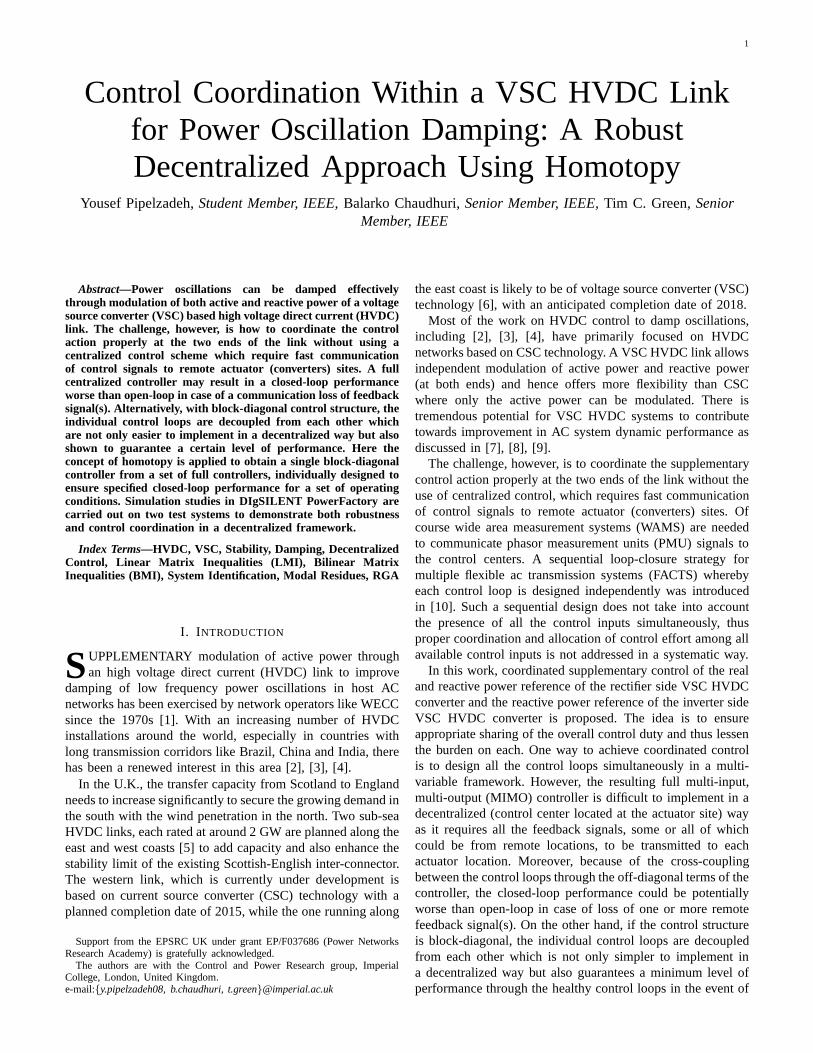
PWM was considered for the control of the VSC HVDCsystem and the converters were represented by their averagedmodel. The dc link was represented by a lumped parametermodel. A decoupled current control strategy in the modifiedreference frame (d′q′) and standard PI controllers were used,see Fig. 3(a),(b). PLL locks thed′-axis to the AC voltage atthe inverter PCC (Eac) to ensure decoupled control [22].
1) Rectifier Control:The rectifier operates inP−Q controlmode with decoupled control strategy [22] as shown in Fig.3(c). The reference values of the current components werederived as:
i′∗
d =2P ∗
rec
3Eac
, i′∗
q = −2Q∗
rec
3Eac
(13)
2) Inverter Control: The inverter operates inVdc−Q modemaintaining constant dc bus voltage and unity power factor onthe point of common coupling, as shown in Fig. 3(d).
C. Control Loop Selection
All nodes were considered as potential sites for PMU feed-back, such that time-synchronized phase angle measurementsdata is available at the control centers of the VSC HVDC.
For best feedback signals, residue analysis [20], [23] andrelative gain array (RGA) were used to identify the mostappropriate control-loops avoiding possible interactions [24].
RGA can be an additional tool to the residue analysisproviding a systematic method for measuring two-way inter-actions between a determined input and output. It has beenwidely reported and commonly used in power system studies[25],[26],[27].
There are 4 possible control (modulation) inputsPrmod,Qrmod, Vdcimod andQimod, and 11 possible outputs (the phase
5
d
q
dq
acE
(b)
mindi
maxqi
minqi
di
qi
Qrec
Current
Control
Loop
Converter
dm
qm
(c)
- )(sKP
- )(sKQ
*′di
*qi
minqi
maxdi
mindi
maxqi
Prec*
Qinv*
Qinvmod
di
qi
Qinv
Current
Control
Loop
Converter
dm
qm
(d)
- )(sKV
- )(sKQ
*′di
*qi
minqi
maxdi
mindi
maxqi
Vdc inv
Vdc inv*
Qrec*
Qrecmod
Prec
Prec mod
-
qcel iL
(a)qi
dm′di
qm
acE+
)(sKI
-
dcel iL
+*
qi-
Current Control
loop
)(sKI
maxdi
di*
Fig. 3. (a) Inner current control (b) modified reference frame for decoupledcontrol (c) rectifier control (d) Inverter control.
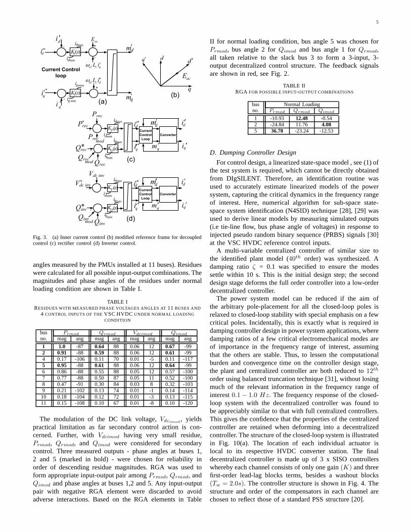
angles measured by the PMUs installed at 11 buses). Residueswere calculated for all possible input-output combinations. Themagnitudes and phase angles of the residues under normalloading condition are shown in Table I.
TABLE IRESIDUES WITH MEASURED PHASE VOLTAGES ANGLES AT11 BUSES AND
4 CONTROL INPUTS OF THEVSC HVDC UNDER NORMAL LOADINGCONDITION
bus Prmod Qrmod Vdcimod Qimod
no. mag ang mag ang mag ang mag ang
1 1.0 -87 0.64 88 0.06 12 0.67 -992 0.91 -88 0.59 88 0.06 12 0.61 -994 0.17 -106 0.11 70 0.01 -5 0.11 -1175 0.95 -88 0.61 88 0.06 12 0.64 -996 0.86 -88 0.55 88 0.05 12 0.57 -1007 0.77 -88 0.50 87 0.05 11 0.52 -1008 0.47 -91 0.30 84 0.03 8 0.32 -1039 0.21 -102 0.13 74 0.01 -1 0.14 -11410 0.18 -104 0.12 72 0.01 -3 0.13 -11511 0.15 -108 0.10 67 0.01 -8 0.10 -120
The modulation of the DC link voltage,Vdcimod, yields
practical limitation as far secondary control action is con-cerned. Further, withVdcimod having very small residue,Prmod, Qrmod, and Qimod were considered for secondarycontrol. Three measured outputs - phase angles at buses 1,2 and 5 (marked in bold) - were chosen for reliability inorder of descending residue magnitudes. RGA was used toform appropriate input-output pair amongPrmod, Qrmod, andQimod and phase angles at buses 1,2 and 5. Any input-outputpair with negative RGA element were discarded to avoidadverse interactions. Based on the RGA elements in Table
II for normal loading condition, bus angle 5 was chosen forPrmod, bus angle 2 forQimod and bus angle 1 forQrmod,all taken relative to the slack bus 3 to form a 3-input, 3-output decentralized control structure. The feedback signalsare shown in red, see Fig. 2.
TABLE IIRGA FOR POSSIBLE INPUT-OUTPUT COMBINATIONS
bus Normal Loadingno. Prmod Qrmod Qimod
1 -10.93 12.48 -0.542 -24.84 11.76 4.085 36.78 -23.24 -12.53
D. Damping Controller Design
For control design, a linearized state-space model , see (1)ofthe test system is required, which cannot be directly obtainedfrom DIgSILENT. Therefore, an identification routine wasused to accurately estimate linearized models of the powersystem, capturing the critical dynamics in the frequency rangeof interest. Here, numerical algorithm for sub-space state-space system identification (N4SID) technique [28], [29] wasused to derive linear models by measuring simulated outputs(i.e tie-line flow, bus phase angle of voltages) in response toinjected pseudo random binary sequence (PRBS) signals [30]at the VSC HVDC reference control inputs.
A multi-variable centralized controller of similar size tothe identified plant model (40th order) was synthesized. Adamping ratioζ = 0.1 was specified to ensure the modessettle within 10 s. This is the initial design step; the seconddesign stage deforms the full order controller into a low-orderdecentralized controller.
The power system model can be reduced if the aim ofthe arbitrary pole-placement for all the closed-loop polesisrelaxed to closed-loop stability with special emphasis on afewcritical poles. Incidentally, this is exactly what is required indamping controller design in power system applications, wheredamping ratios of a few critical electromechanical modes areof importance in the frequency range of interest, assumingthat the others are stable. Thus, to lessen the computationalburden and convergence time on the controller design stage,the plant and centralized controller are both reduced to12th
order using balanced truncation technique [31], without losingmuch of the relevant information in the frequency range ofinterest0.1 − 1.0 Hz. The frequency response of the closed-loop system with the decentralized controller was found tobe appreciably similar to that with full centralized controllers.This gives the confidence that the properties of the centralizedcontroller are retained when deforming into a decentralizedcontroller. The structure of the closed-loop system is illustratedin Fig. 10(a). The location of each individual actuator islocal to its respective HVDC converter station. The finaldecentralized controller is made up of 3 x SISO controllerswhereby each channel consists of only one gain(K) and threefirst-order lead-lag blocks terms, besides a washout blocks(Tw = 2.0s). The controller structure is shown in Fig. 4. Thestructure and order of the compensators in each channel arechosen to reflect those of a standard PSS structure [20].

6
Qimod
Prmod
modQr
-0.93482 (s-4.583) (s+16.37)
(s+28.39) (s+20.7) (s+8.019)
0.020656 (s+31.39) (s+24.26)
(s+28.55) (s+24.54) (s+23.65)
2s
1+ 2s
2s
1+ 2s
2s
1+ 2s 0.20992 (s+6.441) (s+9.96)
(s+18.37) (s+42.49) (s+9.92)
Bus angle 5
Bus angle 2
Bus angle 1
Fig. 4. Parameters of the PSSs for the VSC converters. Feedback signalstaken relative to phase angle of bus 3.
E. Modal Analysis
The eigen-analysis of the study system was carried out forvarious scenarios. Table III shows the critical eigen values ofthe system under normal (400 MW tie-flow) and heavy loading(600 MW tie-flow) conditions.
TABLE IIIDAMPING RATIOS AND FREQUENCIES OF CRITICAL MODES
Loading Base system Centralized case Decentralized caseCondition ζ, % f, Hz ζ, % f, Hz ζ, % f, Hz
Normal400 MW
1.5 0.568 8.1 0.556 11.3 0.5478.4 1.064 8.3 1.065 8.2 1.0658.0 1.099 7.8 1.099 7.4 1.097
Heavy600 MW
0.7 0.540 10.0 0.513 12.5 0.5168.6 1.060 8.6 1.061 8.5 1.0597.7 1.092 7.7 1.092 7.0 1.092
F. Non-linear Simulation
Time domain simulation were conducted in DIgSILENTPowerFactory for 20 s to further demonstrate performancerobustness of the decentralized controller in the presenceof system nonlinearities, including saturation. The dynamicperformance of the system for different loading condition isshown in Figs 5 and 6.
1) Normal Loading condition:A three-phase solid selfclearing fault at bus 8 for 83ms (≈ 5 cycles) was createdto trigger the inter-area oscillations – see Fig. 5 (a,b).
The dynamic response of the system is shown in Fig. 5(a)in terms of oscillations the tie-line power flow triggered bythe above disturbance. Without any supplementary control thesystem response (in blue) is unacceptably oscillatory whilewith control, satisfactory response is achieved wherein theoscillations settle within 10-12 s. The relative angular separa-tion of machine #1 from that of #3 is shown in subplot 5(b).Its evident from subplot 5(d) that active power modulationof the HVDC link mainly contributes towards stabilizingthe oscillations with the reactive power modulation havingminimal influence.
2) Heavy Loading condition:The dynamic behavior of thesystem following a 3-phase self clearing fault for 5 cycles onthe inverter bus #9 of the AC system is illustrated in Fig. 6.
The power oscillation is seen to be light damped with non-linearities becoming noticeable, this is due to the increase intie-line transfer, see blue trace in subplot 6(a). The modulatedDC link power is demonstrated in subplot 6(c). As expected,the control effort demanded from the heavy loading condition
15129630 [s]
433.
422.
411.
400.
389.
378.
P7-9: MW (no control)P7-9: MW (with control) (a)
15129630 [s]
12.
11.
9.
8.
7.
6.
G1-G3: deg (no control)G1-G3: deg (with control) (b)
15129630 [s]
210.
205.
200.
195.
190.
185.
Pdc: MW (with control) (c)
15129630 [s]
15.
10.
5.
0
-5.
-10.
Contol effort: Prmod, MW Contol effort: Qrmod, MVArContol effort: Qimod, MVAr (d)
Tie-line flow Angular separation between G1 and G3
DC link output power Control efforts
Modulated DC link powerReal power modulation is most effective for damping this network.
Reactive power support has minimal influencein damping contribution
Modulating DC link power damps the AC network oscillations
DIg
SIL
EN
T
Fig. 5. Dynamic performance of the system under the normal loadingcondition. Plotted variables described below each subplot.
15129630 [s]
80
60
40
20
0
bus 2 - bus 4: deg (no control)bus 2 - bus 4: deg (with control) (b)
15129630 [s]
250
230
210
190
170
150
Pdc: MW (no control)Pdc: MW (with control) (c)
15129630 [s]
800
700
600
500
400
300
P7-9: MW (no control)P7-9: MW (with control) (a)
15129630 [s]
60
30
0
-30
-60
-90
-120
Control effort: Prmod, MWControl effort: Qrmod, MVArControl effort: Qimod, MVAr (d)
Tie-line flow Bus angle differentbetween buses 2 and 4
DC link power output Control effort
Highly oscillatory with non-linearities
Real power modulation most effective for damping.
More control energy required than the previous case (400 MW)
DIg
SIL
EN
T
Fig. 6. Dynamic performance of the system for the heavy loading condition.Plotted variables described below each subplot.
is substantially higher relative to the normal loading condition.Since a fault is applied to the inverter side, a sharp increase ininverter side reactive powerQimod is seen (red plot) in 6(d).Similar to the normal loading condition, active power modula-tion mainly contributes towards damping the oscillatory mode,with reactive power modulation becoming more evident underthe heavy loading operating conditions – compare subplots5(d) and 6(d).
IV. CASE STUDY II: FOURTEEN-MACHINE, FIVE-AREA
SYSTEM
The proposed approach was validated on a more complexnetwork, representing the Australian equivalent power system.The network shown in Fig.7 has been adopted as an IEEEbenchmark for stability studies. A description of the systemincluding machine, excitation system, and network parameterscan be found in[32]. To provoke a more oscillatory behavior,

7
6 of the 14 PSSs (G1, G6, G8, G9, G11, G13) were placed outof service. The basis of the choice of which PSS to switch offwas participation factor analysis. A VSC HVDC link is addedbetween buses #102 and #217 (the region with the highestpower transfer). The VSC HVDC is rated at250 MVA, withline ratings of±150 kV. The steady state HVDC ratings aresimilar to those in Section III-A. Small signal analysis revealsthree poorly damped inter-area modes.
G2
404
201
SVS
SVS
SVS
SVS
SVS
SVS
G10
G5
G4
406
405
409
411
407
408
410
401
402
403
412
413
414
415
416
205
206
204
202
209
210
213
214
217
203
208
211
212
209 207
102
216
G7
302312
313314
305
G6
301303
304
306307308
315
509
507
G13
G12
501
504
508
502
505
G14
503
506
G1
101
309310311
G9
G8
G11
G3
Area #1
Area #5
Area #4
Area #3
Area #2
VSC HVDC
Control
center
Phasor Data
Concentrator
Ptie
Qr
mod Qi
mod
Ptie#315-509
#303-305
Ptie#205-206
Control
center
Pr
mod
Fig. 7. Test system II: Fourteen-machine, Five-area systemwith a VSCHVDC link (in blue). Secondary control loops with remote feedback signalsfrom PMUs are shown in red.
A. Damping Controller Design
The objective here is similar to that of Section III. Thecontroller is designed to ensure that modal oscillations corre-sponding to each of the three critical inter-area modes settlewithin 10–15 s for a range of operating conditions. Linearizedstate-space models of30th order were found to accuratelycapture the dynamics of the power system. The plant andcontroller was further reduced to21st order with little relevantinformation lost in the frequency range of interest, as shownin Fig.9. Here, a base case and an outage case (tie-line #205-416 out of service) are reported. All nodes were considered aspotential sites for PMU feedback with tie-line flows considered
for remote feedback signal, as shown in Fig. 7. Modal residuesreveal power flows in tie-lines #303-305, #315-509 and #205-206 as appropriate feedback signals forPrmod, Qrmod, andQimod, respectively. The synthesized decentralized controlleris a 3 x SISO decentralized controller, whereby each input-output channel is of7th order, as shown in Fig. 8.
0.0016939 (s+3.206) (s-4.548) ( + 8.379s + 27.8) ( + 106.8s + 6394)
(s+22.23) (s+3.762) (s+1.832) ( + 7.087s + 23.6) ( + 6.847s + 84.64)2s2s
2s2s2s
1+ 2sPrmod
2s2s2s
1+ 2s
1.781 (s+11.14) (s+3.586) ( + 14.27s + 51.68) ( + 4.01s + 6.06)
(s+11.05) (s+8.105) (s+5.542) ( + 4.757s + 8.003) ( + 22.24s + 305)2s 2s modQr
2s
1+ 2s Qimod 0.20259 (s+18.11) (s+13.04) (s+7.439) (s+5.53) (s+4.134) (s+2.982)
(s+11.78) (s+7.111) (s+2.795) ( + 37.38s + 349.6) ( + 12.71s + 42.48)2s 2s
206_205#tieP
305_303#tieP
519_315#tieP
Fig. 8. Parameters of the PSSs for the VSC converters (real and reactivepower modulation).
The frequency response of the closed loop system withcentralized controller is comparable to that of the decentralizedcontrol, as shown in Fig.9.
10−1
100
101
102
−40
−30
−20
−10
0
10
20
30
40
Frequency response of the closed−loop system
frequency (rad/sec)
gain
(dB
)
centralized control − 30th order centralized control − 21st order decentralized control − 21st order
inter−area mode #2
inter−areamode #1
inter−area mode #3
frequency (Hz)
Ptie
#303−305P
rmod
Ptie
#315−509
Qrmod
Qimod
Ptie
#205−206
Fig. 9. Frequency response of the closed loop system (outagecase) withcentralized and decentralized control
From our experience, the feasibility of the algorithm de-pends on the initial centralized controller. The solver inMATLAB may result in numerical issues during the designof the decentralized control if models beyond the order of 30are considered. We note that non-convergence of the algorithmfor some centralized controllers does not generally indicatethat the decentralized control problem has no solution. Asdiscussed in Section III-D, model reduction techniques canbe applied to reduce the plant size since only a few criticalelectromechanical modes in the frequency range (0.1 Hz –2.0 Hz) are of interest. For the case studies considered here,reduced order plant and centralized controller models wereconsidered for the design of the decentralized controller.
B. Eigen value Analysis
Eigen-analysis was performed for various operating condi-tions. Table IV shows the critical modes of the system underthe base and outage scenarios. It’s evident that the closed-loop system performance with decentralized control is slightlydegraded from that of the centralized case. The next section

8
examines the closed loop performance of the decentralizedcontrol against the centralized case when a signal loss occurs.
TABLE IVDAMPING RATIOS AND FREQUENCIES OF CRITICAL MODES
Operating Base system Centralized case Decentralized casecondition ζ, % f, Hz ζ,% f, Hz ζ, % f, Hz
Base7.5 0.30 20.0 0.28 13.0 0.308.2 0.35 11.5 0.35 12.8 0.384.9 0.56 13.5 0.56 15.1 0.57
Outage5.6 0.26 17.3 0.26 13.8 0.2710.2 0.34 17.1 0.33 13.3 0.374.8 0.55 9.2 0.54 15.3 0.57
C. Signal loss
An important aspect is the effectiveness of the controllersinthe event of a signal communication failure. Thus, a questionarises; what is the impact on the closed loop system with(i) a centralized controller against that of (ii) a decentralizedcontroller when a signal loss occurs? The conceptual idea isshown below in Fig. 10.
Power
System with
VSC HVDC
link
G(s)
r1
r2
r3
-
-
-
Decentralized
controller 305_303#tieP
519_315#tieP
206_205#tieP
Signal communication loss
)(sGD
modrP
modrQ
modiQ
)(PrsG
VSC
)(QrsG
VSC
)(QisG
VSC
Power
System with
VSC HVDC
link
G(s)
r1
r2
r3
-
-
-
Centralized
controller
modrP
modrQ
modiQ
Signal communication loss
)(sGC
519_315#tieP
206_205#tieP
# 305_303tieP
Fig. 10. Closed loop system with (a) decentralized control,(b) centralizedcontrol. Feedback signal loss shown in red.
Fig. 11 shows the frequency domain response of the closedloop system with a centralized control (upper subplot) andwith a decentralized control (middle subplot) in the event of acommunication signal loss fromPtie#303−305. Interestingly,this signal loss mainly influences the dynamic response inmode #3. With the centralized case the closed-loop perfor-mance is worsened with respect to its open loop value as themode has shifted further towards the imaginary axis. This isdue to the cross-coupling between the control loops throughthe off-diagonal terms of the controller. However, with thedecentralized case, the ability to damp this particular modeis degraded with respect to its nominal closed loop but themode is shifted towards its open loop value. This is becausethe control structure is block-diagonal and individual controlloops are decoupled from each other, which is not only easierto implement in a decentralized way, but also ensures a certainlevel of performance through the healthy control loops in theevent of loss of one or more (but not all) remote feedbacksignals.
A standard PMU delay of 20 ms (corresponding to 50 Hzsampling) was considered and tested for possible performancedeterioration up to a delay of 100 ms. However, as expectedthe low frequency (0.1 to 2 Hz) behavior was hardly affectedby delays up to 100 ms. Of course, in the rare event of thisdelay going above 500 ms, the closed-loop response wouldstart deteriorating. In such cases delays need to be considered
−0.5 −0.4 −0.3 −0.2 −0.1 00
1
2
3
4 ζ =0.1
real part, s −1
imag
inar
y pa
rt, r
ads
−1
System eigenvalues with centralized control after loss of feedback signal Ptie
#303 − 305
no control without signal loss with signal loss
−0.5 −0.4 −0.3 −0.2 −0.1 00
1
2
3
4 ζ =0.1
real part, s −1
imag
inar
y pa
rt, r
ads
−1
System eigenvalues with decentralized control after loss of feedback signal Ptie
#303 − 305
0 5 10 15 20 25−50
0
50
Impulse response of system after loss of signal Ptie
#303−305
time (sec)
∆ P
tie #
205−
206,
MW
no control without signal loss with signal loss
no control with centralized control with decentralized control
desired closed−loop dampingratio (conic sector)
mode #1
mode #2
mode #2mode shifts towards it’s openloop value (decoupled)
mode #3
mode #3
mode #1
impact on mode #3
due to cross−coupling between input−output pairs
Fig. 11. Frequency and time-domain response of the system inthe event ofcommunication loss of signalPtie#303 − 305.
explicitly in the design stage although this aspect was notconsidered in this paper.
Fault tolerant design techniques could have been employed,rather than using a decoupled (family of SISO) structure toensure a degree of robustness against sensor failure (or signalloss). However, the primary objective behind adopting a setofdecoupled SISO controller here was ease of implementationwith just one remote signal communicated to each actuatorsite while a MIMO controller (centralized) requires commu-nication of all the remote feedback signals to every actuatorlocation.
D. Non-Linear Simulation
To demonstrate the performance robustness of the dampingcontroller across a range of operating conditions, a numberof disturbances were simulated to trigger the multi-modaloscillation. Here, a fault on tie-line #205-416 for a durationof 100ms followed by opening of the circuit breakers, wasconsidered. The objective is to demonstrate the ability of thedecentralized controller to provide adequate damping across allthe operating conditions that were considered in the design.It’s evident from Fig.12(a-d) that the system response arestabilized within 10–15s.
The variation in the power output of the DC link is shownin Fig.12(d). Interestingly, a combination of both active andreactive power support are needed to effectively damp theAC oscillations, whereas in the previous case, active powercontrol mainly contributed in power oscillation damping, seeFig.12(f). For bulk power systems, a mixture of active andreactive power are usually best suited for damping the oscil-lations; a finding that is in agreement with [7],[17],[33].
To understand the non-linear behavior in the reactive powermodulationQrmod, shown in blue in Fig. 12(f), the variation inthe HVDC actuator control parameters need to be analyzed.During the fault, the dc bus voltages at both ends increasesharply due to reduction of ac side power transfer. This isfollowed by oscillations inVdcr due to the dc link dynamics,while Vdci is regulated to a constant value, see Fig 13(a,b).id and iq are seen to have non-linearities 13(c-e), resultingfrom limiting hitting in the current control loop (see Fig. 3(a)).

9
2520151050 [s]
575.540.505.470.435.400.
Ptie 3 - 5: MW (no control) Ptie 3 - 5: MW (with control) (a)
2520151050 [s]
700.620.540.460.380.300.
Ptie 2 - 4: MW (no control) Ptie 2 - 4: MW (with control) (b)
2520151050 [s]
200.120.
40.-40.
-120.-200.
Control effort: Prmod, MWControl effort: Qrmod, MVAr Control effort: Qimod, MVAr (f)
2520151050 [s]
-6.0-12.-18.-23.-29.-35.
G14 - G1: deg (no control) G14 - G1: deg (with control) (c)
2520151050 [s]
255.229.203.177.151.125.
Pdc: with control (e)
2520151050 [s]
2.0-3.4-8.8-14.-20.-25.
G12 - G1: deg (no control) G12 - G1: deg (with control) (d)
DC link power
Machine angular separation Machine angular separation
Tie-line flow (Area 3-5) Tie-line flow (Area 2-4)
DC link power modulated by a combination of real and reactive power control
Coordinated control by real and reactive power control
Control effort
DIg
SIL
EN
T
Fig. 12. Dynamic response with tie-line 205-416 outage. Plotted variablesdescribed below each subplot.
Consequently, the variation in active and reactive power willfollow those of the currents – see relationship (13).
2520151050 [s]
315.
312.
309.
306.
303.
300.
Vdcr: kV (a)2520151050 [s]
313.
311.
308.
305.
303.
300.
Vdci: kV (b)
2520151050 [s]
0.80
0.52
0.25
-0.03
-0.30
-0.58
East Side: iqi, kA (f)
2520151050 [s]
-1.12
-1.36
-1.60
-1.84
-2.09
-2.33
West Side: idr, kA (c)
2520151050 [s]
1.80
1.10
0.40
-0.30
-1.00
-1.70
West Side: iqr, kA (e)
2520151050 [s]
2.24
2.01
1.77
1.54
1.30
1.07
East Side: idi, kA (d)
DC link voltageRectifier end
DC link voltageInverter end
DC link voltagevaries as it isnot controlledon the recifier end
DC link voltagetightly controlledon the inverter end
d-axis currentRectifier end
q-axis currentRectifier end
q-axis currentInverter end
d-axis currentInverter end
DIg
SIL
EN
T
Fig. 13. HVDC actuator parameters dynamic response following tie-line205-416 outage.
E. Robustness Validation
The robustness of the proposed decentralized control ap-proach was verified for a range of operating conditions thatwere not consideredin the design. Its assume that tie-line205-406 is out of service due to maintenance and a fault issimulated on bus #207, followed by an outage of tie-line 207-209. The fault at this location is certainly a severe one asfar as the transient stability is concerned, since this tie-linehas one of the highest tie-flows. The dynamic response of thesystem following thisn− 2 contingency is shown in Fig. 14.As expected, the amplitude of the power oscillations is morethan those in the previous case study, see subplots 14(a-d).The
2520151050 [s]
725.
605.
485.
365.
245.
125.
Ptie 2 - 4: MW (no control)Ptie 2 - 4: MW (with control) (a)
2520151050 [s]
1570.
1326.
1082.
838.
594.
350.
Ptie 1 - 3: MW (no control)Ptie 1 - 3: MW (with control) (b)
2520151050 [s]
250.150.50.
-50.-150.-250.
Control effort: Prmod, MWControl effort: Qrmod, MVArControl effort: Qimod, MVAr (f)
2520151050 [s]
40.14.
-12.-38.-64.-90.
G14 - G1: (deg) no controlG14 - G1: (deg) with control (c)
2520151050 [s]
255.
213.
171.
129.
87.
45.
Pdc: with control (e)
2520151050 [s]
170.153.136.119.102.85.
G11 - G1: (deg) no controlG11 - G1: (deg) with control (d)
Control effortDC link power
Machine angular separation Machine angular separation
Tie-line flow (Area 2 - 4) Tie-line flow (Area 1 - 3)
Mix of real and reactive support
Highly oscillatory system response
During real and reactivepower modulation, actuator limits are constantly hit due to severity of the fault
DIg
SIL
EN
T
Fig. 14. Dynamic performance of the system following a 3 phase fault onbus #207, followed by tie-line 207-209 outage.
imposed limits on the current control result in a higher levelof saturation in the modulated DC link, see subplot 14(e).
The fault scenario considered here is far more severe thanthe previous case with greater angular separation apparent–compare 12(c) with 14(c). Reactive power modulation be-comes an important consideration in addition to real powerunder highly stressed conditions [17] demanding more reactivepower support – compare 12(f) with 14(f). Control coordina-tion ensures appropriate allocation/sharing of the overall dutyamongst the active and reactive power as seen in subplot 14(f).
V. CONCLUSION
The application of homotopy is demonstrated for coordi-nated supplementary control of active and reactive power atboth ends of a VSC HVDC link. The proposed approachachieves coordinated control with a decentralized controlstructure and thus, obviates the need for fast communication ofcontrol signals to remote control centres/ actuator (converter)site. Moreover, a minimum level of closed-loop performanceis guaranteed in the event of loss of remote feedback signal(s)unlike a centralized approach where the performance could beworse due to cross-coupling between control loops. Further, anextension to the standard homotopy framework was proposedsuch that a single decentralized controller is synthesizedfroma set of centralized controllers designed for different operatingconditions, thereby ensuring robustness and control coordina-tion are simultaneously achieved.
REFERENCES
[1] R. L. Cresap, W. A. Mittelstadt, D. N. Scott, and C. W. Taylor,“Operating experience with modulation of the pacific HVDC intertie,”IEEE Transactions on Power Apparatus and Systems, vol. PAS-97, no. 4,pp. 1053–1059, 1978.
[2] M. Xiao-ming and Z. Yao, “Application of HVDC modulationindamping electromechanical oscillations,” inproceedings of IEEE PowerEngineering Society General Meeting, 2007, pp. 1–6.
[3] J. He, C. Lu, X. Wu, P. Li, and J. Wu, “Design and experimentofwide area HVDC supplementary damping controller considering timedelay in china southern power grid,”IET Generation, Transmission &Distribution, vol. 3, no. 1, pp. 17–25, 2009.
10
[4] P. Li, X. Wu, C. Lu, J. Shi, J. Hu, J. He, Y. Zhao, and A. Xu,“Implementation of CSG’s wide-area damping control system: Overviewand experience,” inproceedings of IEEE/PES PSCE Power SystemsConference and Exposition, 2009, pp. 1–9.
[5] “ENSG: Our electricity transmission network: A vision for 2020,” Feb2012. [Online]. Available: www.decc.gov.uk/assets/decc/11/meeting-energy-demand/future-elec-network/4263-ensgFull.pdf
[6] J. Arrillaga, Y. H. Liu, and N. R. Watson,Flexible power transmission:the HVDC options. John Wiley, 2007.
[7] L. Zhang, L. Harnefors, and P. Rey, “Power system reliability andtransfer capability improvement by VSC-HVDC,” inproceedings ofCigre Regional Meeting 20007, 2007.
[8] H. F. Latorre, M. Ghandhari, and L. Soder, “Use of local and remoteinformation in POD control of a VSC-HVDC,” inproceedings ofPowerTech, 2009 IEEE Bucharest, 2009, pp. 1–6.
[9] R. Si-Ye, L. Guo-Jie, and S. Yuan-Zhang, “Damping of power swing bythe control of VSC-HVDC,” inproceedings of IPEC 2007 InternationalPower Engineering Conference, 2007, pp. 614–618.
[10] A. Messina, O. Begovich, J. Lopez, and E. Reyes, “Design of multipleFACTS controllers for damping inter-area oscillations: a decentralisedcontrol approach,”International Journal of Electrical Power & EnergySystems, vol. 26, no. 1, pp. 19–29, 2004.
[11] G. Taranto, J. Shiau, J. Chow, and H. Othman, “Robust decentraliseddesign for multiple FACTS damping controllers,” inGeneration, Trans-mission and Distribution,IET, vol. 144, no. 1. IET, 2002, pp. 61–67.
[12] R. Ramos, L. Alberto, and N. Bretas, “A new methodology for thecoordinated design of robust decentralized power system dampingcontrollers,” IEEE Transactions on Power Systems, vol. 19, no. 1, pp.444–454, 2004.
[13] G. Zhai, M. Ikeda, and Y. Fujisaki, “Decentralized H [infinity] con-troller design: a matrix inequality approach using a homotopy method,”Automatica, vol. 37, no. 4, pp. 565–572, 2001.
[14] Y. Wang, “Time-delayed dynamic output feedback H controller designfor civil structures: a decentralized approach through homotopic trans-formation,” Structural Control and Health Monitoring, 2009.
[15] M. Chilali and P. Gahinet, “Hinfinity design with pole placementconstraints: an lmi approach,”IEEE Transactions on Automatic Control,vol. 41, no. 3, pp. 358 –367, Mar. 1996.
[16] B. Chaudhuri and B. Pal, “Robust damping of multiple swing modesemploying global stabilizing signals with a TCSC,”IEEE Transactionson Power Systems, vol. 19, no. 1, pp. 499–506, 2004.
[17] J. Paserbaet al., “Analysis and control of power system oscillation,”CIGRE special publication, vol. 38, no. 07, 1996.
[18] R. Majumder, B. Pal, C. Dufour, and P. Korba, “Design andreal-time implementation of robust FACTS controller for dampinginter-areaoscillation,” IEEE Transactions on Power Systems, vol. 21, no. 2, pp.809–816, 2006.
[19] B. Chaudhuri and B. Pal, “Robust damping of multiple swing modesemploying global stabilizing signals with a TCSC,”IEEE Transactionson Power Systems, vol. 19, no. 1, pp. 499–506, 2004.
[20] P. Kundur, Power system stability and control, ser. The EPRI powersystem engineering series. New York; London: McGraw-Hill,1994.
[21] “IEEE std 421.5 - 2005, IEEE recommended practice for excitationsystem models for power system stability studies,” pp. 1–85, 2006.
[22] C. Schauder and H. Mehta, “Vector analysis and control of advancedstatic var compensators,”IEE Proceedings on Generation, Transmissionand Distribution, vol. 140, no. 4, pp. 299–306, 1993.
[23] S. Ray, B. Chaudhuri, and R. Majumder, “Appropriate signal selectionfor damping multi-modal oscillations using low order controllers,” inPower and Energy Society General Meeting-Conversion and Deliveryof Electrical Energy in the 21st Century, 2008. IEEE, 2008, pp. 1–7.
[24] S. Skogestad and I. Postlethwaite,Multivariable feedback control:analysis and design. Chichester: Wiley, 1996.
[25] L. Zhang, P. X. Zhang, H. F. Wang, Z. Chen, W. Du, Y. J. Cao,andS. J. Chen, “Interaction assessment of FACTS control by RGA forthe effective design of FACTS damping controllers,”IEE ProceedingsGeneration, Transmission and Distribution,, vol. 153, no. 5, pp. 610–616, 2006.
[26] W. Juanjuan, F. Chuang, and Z. Yao, “Design of wams-based multiplehvdc damping control system,”IEEE Transactions on Smart Grid, vol. 2,no. 2, pp. 363–374, 2011.
[27] J. Milanovic and A. Duque, “Identification of electromechanical modesand placement of psss using relative gain array,”IEEE Transactions onPower Systems, vol. 19, no. 1, pp. 410–417, 2004.
[28] P. van Overschee,Subspace identification for linear systems : theory,implementation, applications. Boston: Kluwer Academic, 1996.
[29] I. Kamwa, G. Trudel, and L. Gerin-Lajoie, “Low-order black-box modelsfor control system design in large power systems,”IEEE Transactionson Power Systems, vol. 11, no. 1, pp. 303–311, 1996.
[30] P. E. Wellstead and M. B. Zarrop,Self-tuning Systems. Control andSignal Processing. John Wiley & Sons, 1991.
[31] S. Skogestad, I. Postlethwaite, and I. NetLibrary,Multivariable feedbackcontrol: analysis and design. Wiley New York, 1996.
[32] M. Gibbard and D. Vowles, “Simplified 14-generator model of se australian power system,”http://www.eleceng.adelaide.edu.au/groups/PCON/PowerSystems/IEEE/,2008.
[33] T. Smed and G. Andersson, “Utilizing HVDC to damp power oscilla-tions,” IEEE Transactions on Power Delivery, vol. 8, no. 2, pp. 620–627,1993.
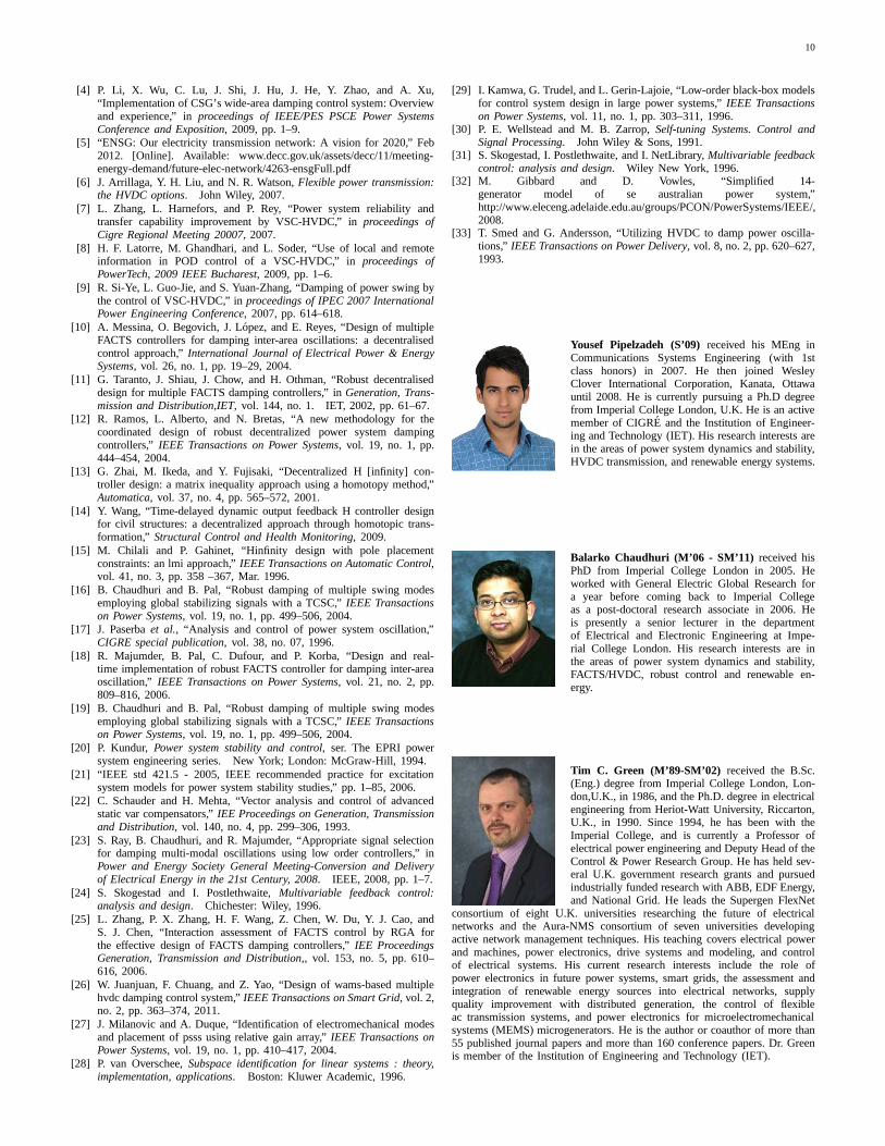
Yousef Pipelzadeh (S’09)received his MEng inCommunications Systems Engineering (with 1stclass honors) in 2007. He then joined WesleyClover International Corporation, Kanata, Ottawauntil 2008. He is currently pursuing a Ph.D degreefrom Imperial College London, U.K. He is an activemember of CIGRE and the Institution of Engineer-ing and Technology (IET). His research interests arein the areas of power system dynamics and stability,HVDC transmission, and renewable energy systems.
Balarko Chaudhuri (M’06 - SM’11) received hisPhD from Imperial College London in 2005. Heworked with General Electric Global Research fora year before coming back to Imperial Collegeas a post-doctoral research associate in 2006. Heis presently a senior lecturer in the departmentof Electrical and Electronic Engineering at Impe-rial College London. His research interests are inthe areas of power system dynamics and stability,FACTS/HVDC, robust control and renewable en-ergy.
Tim C. Green (M’89-SM’02) received the B.Sc.(Eng.) degree from Imperial College London, Lon-don,U.K., in 1986, and the Ph.D. degree in electricalengineering from Heriot-Watt University, Riccarton,U.K., in 1990. Since 1994, he has been with theImperial College, and is currently a Professor ofelectrical power engineering and Deputy Head of theControl & Power Research Group. He has held sev-eral U.K. government research grants and pursuedindustrially funded research with ABB, EDF Energy,and National Grid. He leads the Supergen FlexNet
consortium of eight U.K. universities researching the future of electricalnetworks and the Aura-NMS consortium of seven universitiesdevelopingactive network management techniques. His teaching coverselectrical powerand machines, power electronics, drive systems and modeling, and controlof electrical systems. His current research interests include the role ofpower electronics in future power systems, smart grids, theassessment andintegration of renewable energy sources into electrical networks, supplyquality improvement with distributed generation, the control of flexibleac transmission systems, and power electronics for microelectromechanicalsystems (MEMS) microgenerators. He is the author or coauthor of more than55 published journal papers and more than 160 conference papers. Dr. Greenis member of the Institution of Engineering and Technology (IET).