Control Buck
25
Model Derivation and Control Design of a Buck Converter using Ansoft Simplorer TM By: Marius Marita
Transcript of Control Buck

8/12/2019 Control Buck
http://slidepdf.com/reader/full/control-buck 1/25
Model Derivation and Control Design of a
Buck Converter using
Ansoft SimplorerTM
By:Marius Marita
8/12/2019 Control Buck
http://slidepdf.com/reader/full/control-buck 2/25
Overview
• Problem Statement
• Buck Theory• Derive the Transfer Function
• Investigate the Control Methods
• Simulation Results• Conclusion
• Application: Induction Motor Control
• Questions?
8/12/2019 Control Buck
http://slidepdf.com/reader/full/control-buck 3/25
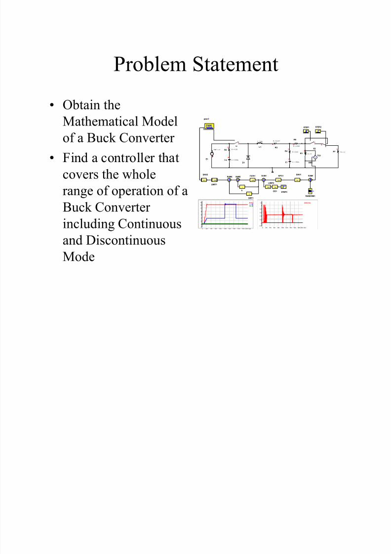
Problem Statement
• Obtain the
Mathematical Model
of a Buck Converter
• Find a controller that
covers the whole
range of operation of a
Buck Converterincluding Continuous
and Discontinuous
Mode
R1.V[
1 .1 24 7 7 7 .RA ND .
t[s]
14
-2
0
2
4
6
8
10
12
0 20m2m 4m 6m 8m 10m 12m 14m 16m 18m
R1 R : = 4
C1 C := 1500u
L1
L := 56u
E1
EMF := 27
C4 C := 1500u
S1
D1
R2 R := 0.02
R3
R := 0.017
R4 R := 0.02
SUM1
NEG
NEG1
GAIN
GAIN1
PWM
pwm1
S& H
SAH1
LIMIT
LIMIT1
R5 R := 1.5
S2
STEP1 STEP2
TS1
SAH2.VAL
t[s]
1.2
-0.2
0
0.2
0.4
0.6
0.8
1
0 20m2m 4m 6m 8m 10m 12m 14m 16m 18m
R6
R := 0.001
STEP3
G(s)
GS1
LIMIT
LIMIT2
SUM2
I
b
SUM4
D
DIFF1
S& H
SAH2
RANDOM
RANDOM1
SUM5
+
V
VM1
8/12/2019 Control Buck
http://slidepdf.com/reader/full/control-buck 4/25
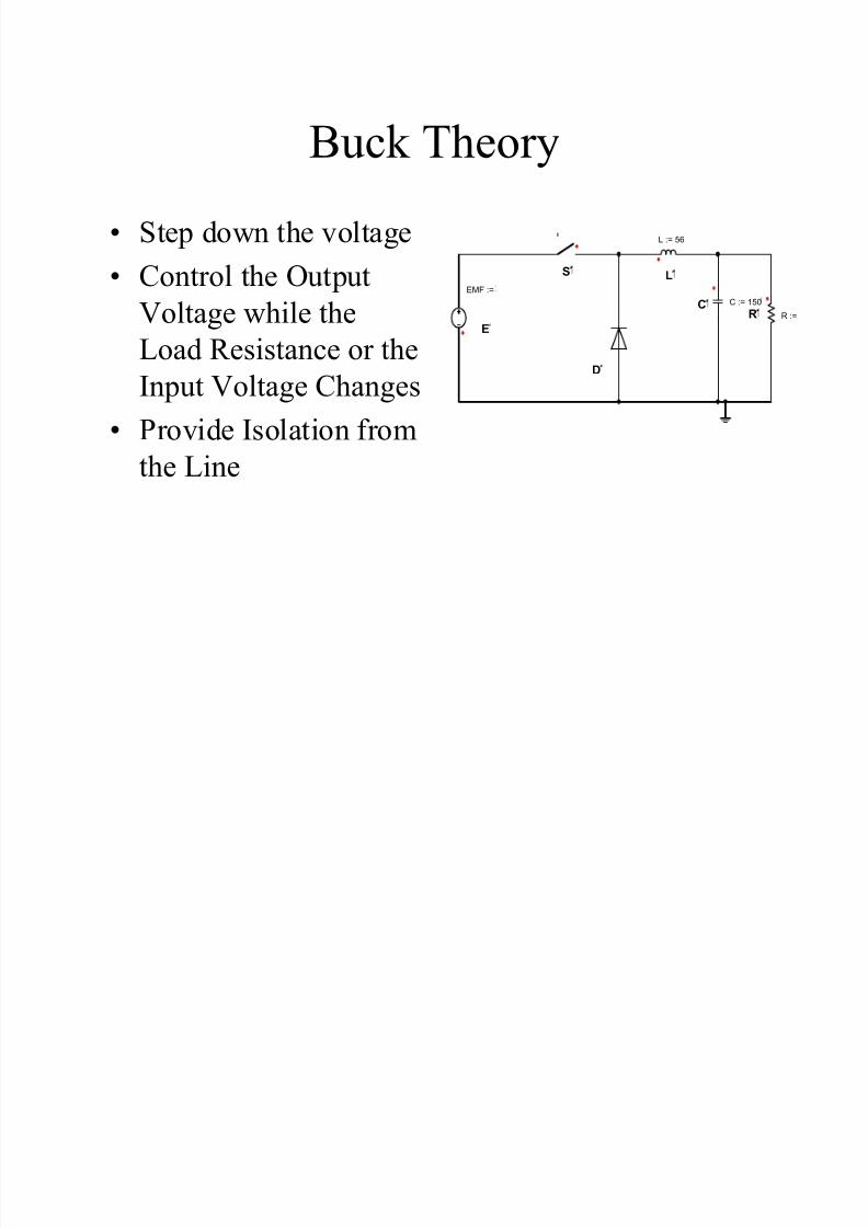
Buck Theory
• Step down the voltage
• Control the Output
Voltage while the
Load Resistance or the
Input Voltage Changes
• Provide Isolation from
the Line
R R :=C C := 150
L
L := 56
E
EMF :=
S
D
8/12/2019 Control Buck
http://slidepdf.com/reader/full/control-buck 5/25
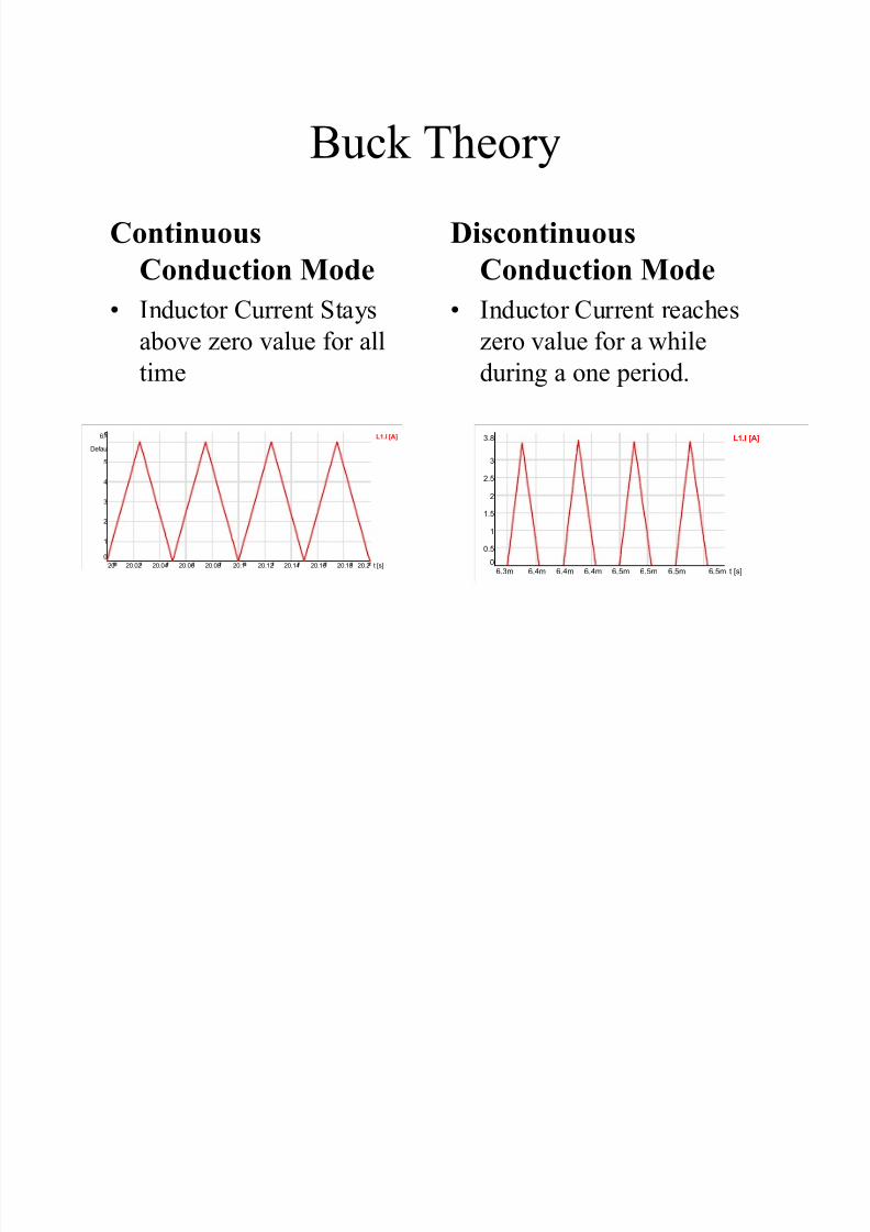
Buck Theory
Continuous
Conduction Mode
• Inductor Current Staysabove zero value for all
time
Discontinuous
Conduction Mode
• Inductor Current reacheszero value for a while
during a one period.
L1.I [A]
t [s]
Defaul
6.
0
1
2
3
4
5
20 20.220.02 20.04 20.06 20.08 20.1 20.12 20.14 20.16 20.18
L1.I [A]
t [s]
3.8
0
0.5
1
1.5
2
2.5
3
6.3m 6.5m6.4m 6.4m 6.4m 6.5m 6.5m 6.5m

8/12/2019 Control Buck
http://slidepdf.com/reader/full/control-buck 6/25
Buck Transfer Function
• TF derived from
changing the On Time
of the Switch resulting
in changing the output
voltage (CCM)
• Load Resistance
changes from 1O, to
1.5O, to 2O, and 3O in
CCM
PWM
R1 R := 1
C1 C := 1500
L1
L := 56
E1
EMF := 2
S1
D1
pwm
CONSTCONS
SUM
STEP
AMPL := 0.
0.44
Continuous Conduction Mode
Simulation Setup

8/12/2019 Control Buck
http://slidepdf.com/reader/full/control-buck 7/25
Buck Transfer Function
• TF derived from Changing
the Load Resistance whilekeeping the On Time of
the PWM Generator
Constant (DCM)
• Load changes from 5O,
7O, 10O, and 12O in
DCM
Discontinuous Conduction Mode
Simulation Setup
PWM
R R :=
C C := 150
L
L := 5
E
EMF :=
S1
D1
pwm
CONSTCONS
0.4
S2
TS
R R := 2
STE
AMPL :
STE
AMPL :

8/12/2019 Control Buck
http://slidepdf.com/reader/full/control-buck 8/25
Buck Transfer Function
• Second Order
Response for CCM
• First Order Response
for DCM
R1.V [R1.I [A
[s]
Defa
15
10.1
1
1
1
1
20.12 57.1024 26 28 30 32 34 36 38 40 42 44 46 48 50 52

8/12/2019 Control Buck
http://slidepdf.com/reader/full/control-buck 9/25
Buck Transfer Function
• Second Order CCMVOut(IN)ss= Output Voltage before adding
the change in Duty Ratio
VOut(FV)ss= Output Voltage Steady State
value after adding the change in the
Duty Ratio
V(PEAK)= Peak Value of the Overshoot
Voltage
T(FV First Time)= Time to the first reach of the
Steady State Voltage
T(PEAK)= Time to the Peak Voltage
Calculate:
• DC Gain:
• Ratio of Peak Value to Final Value:
• Damping Ratio from Table:
ζ=0.55
• Normalized Time to Peak Value: t *from
Table
• Calculated Natural Frequency:
• Transfer Function:
( )
( )
PEAK
Out ss
V V
*
( )
n
PEAK
t
T ω =
( )
2
22
22
22 2
( )2
2
(2 )( )
2 2 (2 )
DC n
n n
n n
DC n
n n
K G s
s s
f
K f G s
s f s f
ω
ζω ω
ω π
π
ζ π π
=+ +
= ⋅ ⋅
⋅ ⋅=
+ ⋅ ⋅ ⋅ ⋅ + ⋅ ⋅
g
g

8/12/2019 Control Buck
http://slidepdf.com/reader/full/control-buck 10/25
Buck Transfer Function
• First Order DCM
V1(in)- Voltage Value before
Load Change OccursV1(out)-Voltage Value after
load change occurred and
reached steady state
T(63%)-Time it takes for thesystem to reach 63% of its
final value
• K - DC Gain
• t - 63.2% of the final
value
( )
1
H s
sτ
=
+

8/12/2019 Control Buck
http://slidepdf.com/reader/full/control-buck 11/25
Buck Transfer Function• Continuous Conduction Mode
(CCM)• Discontinuous Conduction
Mode (DCM)
( ) ( )
( ) ( ) ( ) ( )
2 2
2 22
27 2 633( )
2 0.50 2 633 2 633Gs
s s
π
π π
⋅ ⋅=
+ ⋅ ⋅ ⋅ + ⋅
.
( ) DC c
c
w
G s s w= +
0.004850.0048410.0034960.002705Time Constant
(Seconds)
18.918.418.4517.9DC Gain K DC
121075Resistance (ς)
Test 4 Test 3 Test 2 Test 1 •Variable Data

8/12/2019 Control Buck
http://slidepdf.com/reader/full/control-buck 12/25
Investigate Control Methods
• Proportional Integral Derivative (PID)
• Loop Shaping Design (LSD)
• Active Disturbance Rejection Controller
(ADRC)

8/12/2019 Control Buck
http://slidepdf.com/reader/full/control-buck 13/25
Investigate Control Methods
• Classical PID
∫ ⋅+⋅⋅+⋅= edt
d k dt ek ek sG d i pc )(
8/12/2019 Control Buck
http://slidepdf.com/reader/full/control-buck 14/25
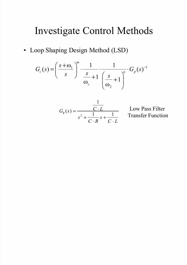
Investigate Control Methods
• Loop Shaping Design Method (LSD)
11
2
1 1( ) ( )
1 1
m
c pn
c
sG s G s s s s
ω
ω ω
−+ = ⋅ ⋅ ⋅ + +
2
1
( )1 1cC LG s
s sC R C L
⋅=+ +
⋅ ⋅
Low Pass Filter
Transfer Function p
8/12/2019 Control Buck
http://slidepdf.com/reader/full/control-buck 15/25
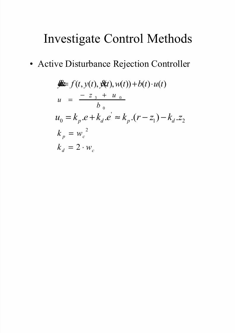
Investigate Control Methods
• Active Disturbance Rejection Controller
3 0
0
z uu
b
− +=
'
0 1 2. . .( ) . p d p d u k e k e k r z k z = + ≈ − −2
2
p c
d c
k w
k w
=
= ⋅
( , ( ), ( ), ( )) ( ) ( ) y f t y t y t w t b t u t = + ⋅&& &
8/12/2019 Control Buck
http://slidepdf.com/reader/full/control-buck 16/25
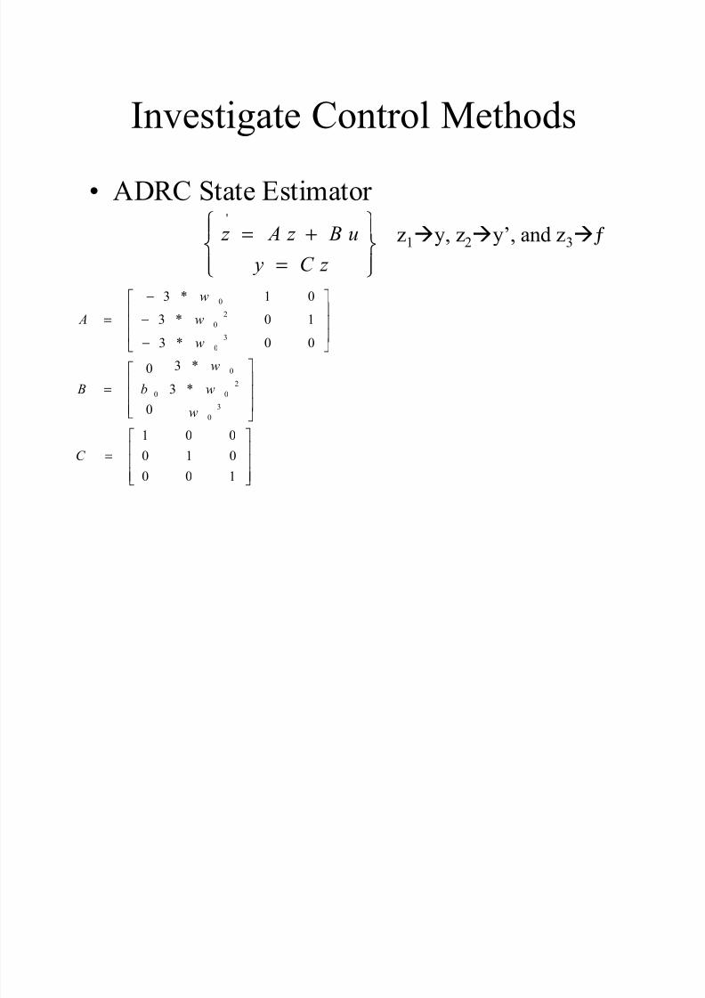
Investigate Control Methods
• ADRC State Estimator '
z A z B u
y C z
= + =
0
2
0
3
0
0
2
0 0
3
0
3 * 1 0
3 * 0 1
3 * 0 0
3 *03 *
0
1 0 0
0 1 0
0 0 1
w
A w
w
w B b w
w
C
−
= − −
=
=
z1
ày, z2
ày’, and z3
àƒ

8/12/2019 Control Buck
http://slidepdf.com/reader/full/control-buck 17/25
Investigate Control Methods
• Evaluate each Control Method based on a
Cost Function of the Form:
2 2
2 2
0 0
(| |) (| |) ( ) ( )
T T
e u e u
max k e max k u k e dt k u dt = ⋅ + ⋅ + ⋅ + ⋅∫ ∫

8/12/2019 Control Buck
http://slidepdf.com/reader/full/control-buck 18/25
Investigate Control Methods
• PID Implementation
R1 R := 4
C1 C := 1500u
L1
L := 56u
E1
EMF := 27
C4 C := 1500u
S1
D1
R2 R := 0.02R3
R := 0.017
R4 R := 0.02
SUM1
NEG
NEG1
GAIN
GAIN1
PWM
pwm1
S & H
SAH1
LIMIT
LIMIT1
R5 R := 1.5
S2
STEP1 STEP2
TS1
R6
R := 0.001
STEP3
G(s)
GS1
LIMIT
LIMIT2
SUM2
I
INT1
D
DIFF1
S & H
SAH2
RANDOM
RANDOM1
SUM5
+
V
VM1

8/12/2019 Control Buck
http://slidepdf.com/reader/full/control-buck 19/25
Investigate Control Methods
• LSD and ADRC more complex
– ADRC Require State Estimator
– LSD easier to implement writing an .m file in
Matlab
8/12/2019 Control Buck
http://slidepdf.com/reader/full/control-buck 20/25

8/12/2019 Control Buck
http://slidepdf.com/reader/full/control-buck 21/25
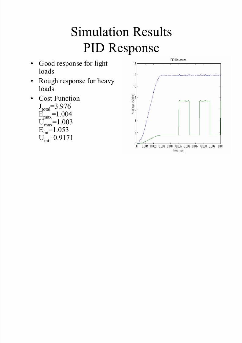
Simulation Results
LSD Response• Good Load
Disturbance
• Better than PID• Cost Function
Jtotal=3.416Emax=0.2239
Umax=1.123Eint=0.1273Uint=1.942
8/12/2019 Control Buck
http://slidepdf.com/reader/full/control-buck 22/25
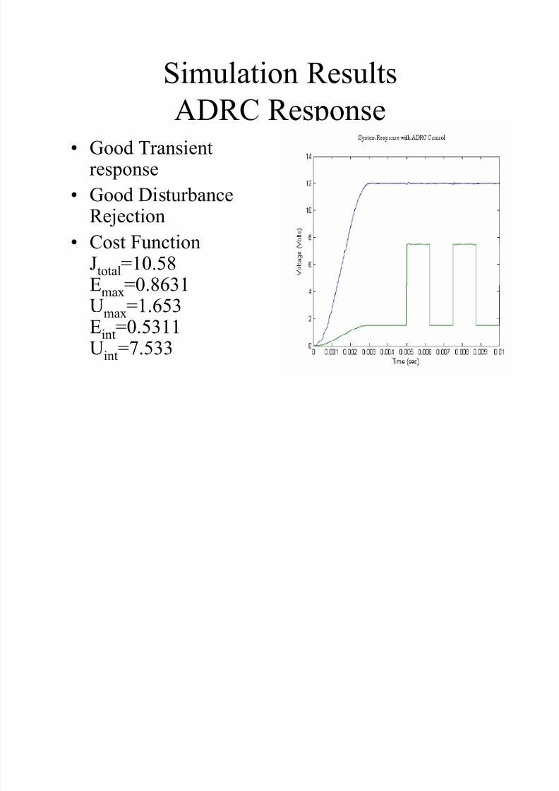
Simulation Results
ADRC Response• Good Transient
response
• Good DisturbanceRejection
• Cost FunctionJtotal=10.58
Emax=0.8631Umax=1.653Eint=0.5311Uint=7.533

8/12/2019 Control Buck
http://slidepdf.com/reader/full/control-buck 23/25
Conclusion
• ADRC is the preferred Control Method
Deals Best with Nonlinearities
• LSD has good load disturbance but can not
make up for Nonlinearities
• PID lags behind ADRC and LSD
Not suitable for a Buck Converter.

8/12/2019 Control Buck
http://slidepdf.com/reader/full/control-buck 24/25
Buck Application:
Induction Motor Control
E1R1
E2
E3
R2
R3
L1
L3
D1 D2 D3
D4 D6
IM1.N [rpm]5 * C2.V [V]
5 * SUM4.VAL
t [s]
2k
-0.2k
0
0.25k
0.5k
0.75k
1k
1.3k
1.5k
1.8k
0 20.25 0.5 0.75 1 1.3 1.5 1.8
C1
C2
S7
PWM
PWM1
CLR
Q1
Q2
Q0
Binary
cntb31
AND3
and33
AND3
and34
AND3
and35
AND3
and36
INV
inv7
AND3
and37
AND3
and31
DAC
VAL
[3:0]
INPUT
dac1
DAC
VAL
[3:0]
INPUT
dac2
DAC
VAL
[3:0]
INPUT
dac3
DAC
VAL
[3:0]
INPUT
dac4
DAC
VAL
[3:0]
INPUT
dac5
DAC
VAL
[3:0]
INPUT
dac6
S1
S2
S3
S4
S5
S6
OR3
or31
OR3
or32
OR3
or33
OR3
or34
OR3
or35
OR3
or36
AND3
and32
INV
inv2
INV
inv3
INV
inv8
INV
inv1
INVinv5
INV
inv6
INV
inv4
INV
inv9
PWM
PWM2
+
V
VM1
CONST
CONST
CONST
CONSTxn
POW1
MUL1
COMP1
LIMIT
LIMIT1
SUM1
N E G
NEG1
CONST
CONST1
MUL3
L2
D5
GAIN
GAIN1
I
INTG1SUM2
D7
IM1.N [rpm]0.140222k
MUL3.VAL36.6495m
ADC
[3:0]
INPUT
VAL
adc1
CLK
clk1
M3 ~ B
A
C
IM1
STEP1
STEP3
SUM4
STEP5
L4
R5
S8
COMP2
STEP2
STEP4
D8 D9 D10
D11D12
D13
Vdc

8/12/2019 Control Buck
http://slidepdf.com/reader/full/control-buck 25/25
Questions?