CONTROL AND PERFORMANCE OF A C H-BRIDGE … · Reactive Power compensation can be obtained by...
12
International Journal of Advances in Engineering & Technology, Jan 2012. ©IJAET ISSN: 2231-1963 508 Vol. 2, Issue 1, pp. 508-519 CONTROL AND PERFORMANCE OF A CASCADED H-BRIDGE MLI AS STATCOM M. Vishnu Prasad and K. Surya Suresh Department of Electrical & Electronics Engineering, SVIET, Nandamuru, AP, India ABSTRACT This paper presents a three-phase cascaded H-Bridge MLI as Static synchronous Compensator (STATCOM) intended for installation on industrial and utility power distribution systems. It proposes a control technique that devotes itself to meeting the demand of reactive power. To implement a separate control for the three phase dc-link voltages, the average active power in each phase can also be adjusted to a target value determined by the dc-link voltage control loop. Then, by forcing the converter neutral voltage to be equal to the counterpart of the equivalent power supply, the STATCOM can be decoupled into three single-phase systems and the line-to- neutral voltage of the equivalent power supply can be used as the input voltage to the corresponding phase leg. Accordingly dc-link voltage maintaining can be simultaneously achieved under unbalanced conditions. K EYWORDS— STATCOM, Multilevel inverter, Reactive power, FACTS. I. INTRODUCTION An AC power system is a complex network of synchronous generators, transmission lines and loads. The transmission lines can be represented mostly as reactive networks composed of series inductors and shunt capacitors. The total series inductance, which is proportional to the length of the line, determines primarily the maximum transmissible power at a given voltage. The shunt capacitance influences the voltage profile and thereby the power transmission along the line. The transmitted power over a given line is determined by the line impedance, the magnitude of voltage and phase angle between the end voltages, the basic operating requirements of an AC power system are that the synchronous generators must remain in synchronism and the voltage must kept close to their rated values. In the late 1980s, the Electric Power Research Institute (EPRI) in the USA formulated the vision of the Flexible AC transmission System (FACTS) in which various Power electronics based controllers regulate Power flow and transmission voltage through rapid control action, mitigate dynamic disturbances. FACTS devices involve the applications of high power electronics in AC transmission networks enables fast and reliable control of power flows and voltages. Reactive Power compensation can be obtained by Series VAR compensation and Shunt VAR compensation. Series compensation modifies the transmission or distribution system parameters, while shunt compensation changes the equivalent impedance of the load. Traditionally, rotating synchronous condensers and fixed or mechanically switched capacitors or inductors have been used for reactive power compensation. However, in recent years, static VAR compensators employing thyristor switched capacitors and thyristor controlled reactors to provide or absorb the required reactive power have been developed [1][3]. The FACTS is a concept based on power-electronic controllers, which enhance the value of transmission networks by increasing the use of their capacity As these controllers operate very fast, they enlarge the safe operating limits of a transmission system without risking stability. FACTS
Transcript of CONTROL AND PERFORMANCE OF A C H-BRIDGE … · Reactive Power compensation can be obtained by...

International Journal of Advances in Engineering & Technology, Jan 2012.
©IJAET ISSN: 2231-1963
508 Vol. 2, Issue 1, pp. 508-519
CONTROL AND PERFORMANCE OF A CASCADED H-BRIDGE
MLI AS STATCOM
M. Vishnu Prasad and K. Surya Suresh
Department of Electrical & Electronics Engineering, SVIET, Nandamuru, AP, India
ABSTRACT
This paper presents a three-phase cascaded H-Bridge MLI as Static synchronous Compensator (STATCOM)
intended for installation on industrial and utility power distribution systems. It proposes a control technique
that devotes itself to meeting the demand of reactive power. To implement a separate control for the three phase
dc-link voltages, the average active power in each phase can also be adjusted to a target value determined by
the dc-link voltage control loop. Then, by forcing the converter neutral voltage to be equal to the counterpart of
the equivalent power supply, the STATCOM can be decoupled into three single-phase systems and the line-to-
neutral voltage of the equivalent power supply can be used as the input voltage to the corresponding phase leg.
Accordingly dc-link voltage maintaining can be simultaneously achieved under unbalanced conditions.
KEYWORDS— STATCOM, Multilevel inverter, Reactive power, FACTS.
I. INTRODUCTION
An AC power system is a complex network of synchronous generators, transmission lines and loads. The transmission lines can be represented mostly as reactive networks composed of series inductors and shunt capacitors. The total series inductance, which is proportional to the length of the line, determines primarily the maximum transmissible power at a given voltage. The shunt capacitance influences the voltage profile and thereby the power transmission along the line. The transmitted power over a given line is determined by the line impedance, the magnitude of voltage and phase angle between the end voltages, the basic operating requirements of an AC power system are that the synchronous generators must remain in synchronism and the voltage must kept close to their rated values. In the late 1980s, the Electric Power Research Institute (EPRI) in the USA formulated the vision of the Flexible AC transmission System (FACTS) in which various Power electronics based controllers regulate Power flow and transmission voltage through rapid control action, mitigate dynamic disturbances. FACTS devices involve the applications of high power electronics in AC transmission networks enables fast and reliable control of power flows and voltages. Reactive Power compensation can be obtained by Series VAR compensation and Shunt VAR compensation. Series compensation modifies the transmission or distribution system parameters, while shunt compensation changes the equivalent impedance of the load. Traditionally, rotating synchronous condensers and fixed or mechanically switched capacitors or inductors have been used for reactive power compensation. However, in recent years, static VAR compensators employing thyristor switched capacitors and thyristor controlled reactors to provide or absorb the required reactive power have been developed [1][3]. The FACTS is a concept based on power-electronic controllers, which enhance the value of transmission networks by increasing the use of their capacity As these controllers operate very fast, they enlarge the safe operating limits of a transmission system without risking stability. FACTS

International Journal of Advances in Engineering & Technology, Jan 2012.
©IJAET ISSN: 2231-1963
509 Vol. 2, Issue 1, pp. 508-519
controllers can be classified as Series controllers, Shunt controllers, Combination of Series - Shunt controllers and Combination of Series- Series controllers. The STATCOM is a shunt-connected reactive-power compensation device that is capable of generating or absorbing reactive power and in which the output can be varied to control the specific parameters of an electric power system [5]. Multilevel inverter has a series of advantages over two-level converter, such as its output waveforms are more similar to the object modulation waves (sinusoidal waves), less skip and harmonics of output voltages, fewer switching losses [12].
II. REACTIVE POWER COMPENSATION TECHNOLOGIES
VAR compensation is defined as the management of reactive power to improve the performance of ac power systems. The concept of VAR compensation embraces a wide and diverse field of both system and customer problems, especially related with power quality issues, since most of power quality problems can be attenuated or solved with an adequate control of reactive power. In general, the problem of reactive power compensation is viewed from two aspects: load compensation and voltage support. In load compensation the objectives are to increase the value of the system power factor, to balance the real power drawn from the ac supply, compensate voltage regulation and to eliminate current harmonic components produced by large and fluctuating nonlinear industrial loads. Voltage support is generally required to reduce voltage fluctuation at a given terminal of a transmission line. Reactive power compensation in transmission systems also improves the stability of the ac system by increasing the maximum active power that can be transmitted. It also helps to maintain a substantially flat voltage profile at all levels of power transmission; it improves HVDC (High Voltage Direct Current) conversion terminal performance, increases transmission efficiency, controls steady-state and temporary over-voltages, and can avoid disastrous blackouts[16]. Traditionally, rotating synchronous condensers and fixed or mechanically switched capacitors or inductors have been used for reactive power compensation. However, in recent years, static VAR compensators employing thyristor switched capacitors and thyristor controlled reactors to provide or absorb the required reactive power have been developed. Also, the use of self-commutated PWM converters with an appropriate control scheme permits the implementation of static compensators capable of generating or absorbing reactive current components [1] [2] with a time response faster than the fundamental power network cycle.
III. FACTS CONTROLLERS
The rapid growth in electrical energy use, combined with the demand for low cost energy, has gradually led to the development of generation sites remotely located from the load centers. In particular, the remote generating stations include hydroelectric stations, which exploit sites with higher heads and significant water flows; fossil fuel stations, located close to coal mines; geothermal stations and tidal-power plants, which are site bound; and, sometimes, nuclear power plants purposely built distant from urban centers. The generation of bulk power at remote locations necessitates the use of transmission lines to connect generation sites to load centers. Furthermore, to enhance system reliability, multiple lines that connect load centers to several sources, interlink neighboring utilities, and build the needed levels of redundancy have gradually led to the evolution of complex interconnected electrical transmission networks. These networks now exist on all continents [7]. The FACTS is a concept based on power-electronic controllers, which enhance the value of transmission networks by increasing the use of their capacity As these controllers operate very fast, they enlarge the safe operating limits of a transmission system without risking stability. Needless to say, the era of the FACTS was triggered by the development of new solid-state electrical switching devices [4]. Gradually, the use of the FACTS has given rise to new controllable systems. Today, it is expected that within the operating constraints of the current-carrying thermal limits of conductors, the voltage limits of electrical insulating devices, and the structural limits of the supporting infrastructure, an operator should be able to control power flows on lines to secure the highest safety margin as well as transmit electrical power at a minimum of operating cost. Doing so constitutes the increased value of transmission assets.

International Journal of Advances in Engineering & Technology, Jan 2012.
©IJAET ISSN: 2231-1963
510 Vol. 2, Issue 1, pp. 508-519
Types of FACTS Controllers: In general FACTS controllers can be divided into the following four categories: a. Series Controllers In principle all the series controllers inject voltage in series with the line. Series connected controller impacts the driving voltage and hence, the current and power flow directly. Static Synchronous Series Compensator (SSSC), Thyristor Controlled Series Compensator (TCSC) etc. are the examples of series controllers. b. Shunt Controllers All shunt controllers inject current into the system at the point of connection. The shunt controller is like a current source, which draws/injects current from/into the line. Static Synchronous Compensator (SSC), Static Synchronous Generator (SSG), Thyristor Controlled Reactor (TCR) etc are the examples of shunt controllers. c. Combined Series-Shunt Controllers This could be a combination of separate shunt and series controllers, which are controlled in a coordinated manner. Combined shunt and series controllers inject current into the system with the shunt part of the controller and voltage in series in the line with the series part of the controller. Unified Power Flow Controller (UPFC) and Thyristor Controlled Phase Shifting Transformer (TCPST) are the examples of shunt series controllers. d. Combined Series-Series Controllers This could be a combination of separate series controllers, which are controlled in a coordinated manner, in a multi-line transmission system or it could be a unified controller, in which series controller provides independent series reactive compensation for each line but also transfer real power among the line via the power link.
IV. STATCOM
The STATCOM (or SSC) is a shunt-connected reactive-power compensation device that is capable of generating or absorbing reactive power and in which the output can be varied to control the specific parameters of an electric power system. It is in general a solid-state switching converter capable of generating or absorbing independently controllable real and reactive power at its output terminals when it is fed from an energy source or energy-storage device at its input terminals. Specifically, the STATCOM considered in this project is a voltage-source converter that, from a given input of dc voltage, produces a set of 3-phase ac-output voltages, each in phase with and coupled to the corresponding ac system voltage through a relatively small reactance. The dc voltage is provided by an energy-storage capacitor[5][6].
Fig.1 STATCOM Principal Diagram
A STATCOM can improve power-system performance in such areas as the following: The dynamic voltage control in transmission and distribution systems, The power-oscillation damping in power-transmission systems, The transient stability, The voltage flicker control and The control of

International Journal of Advances in Engineering & Technology, Jan 2012.
©IJAET ISSN: 2231-1963
511 Vol. 2, Issue 1, pp. 508-519
not only reactive power but also (if needed) active power in the connected line, requiring a dc energy source. A STATCOM is analogous to an ideal synchronous machine, which generates a balanced set of three sinusoidal voltages—at the fundamental frequency—with controllable amplitude and phase angle. This ideal machine has no inertia, is practically instantaneous, does not significantly alter the existing system impedance, and can internally generate reactive (both capacitive and inductive) power. 4.1 Principle of Operation
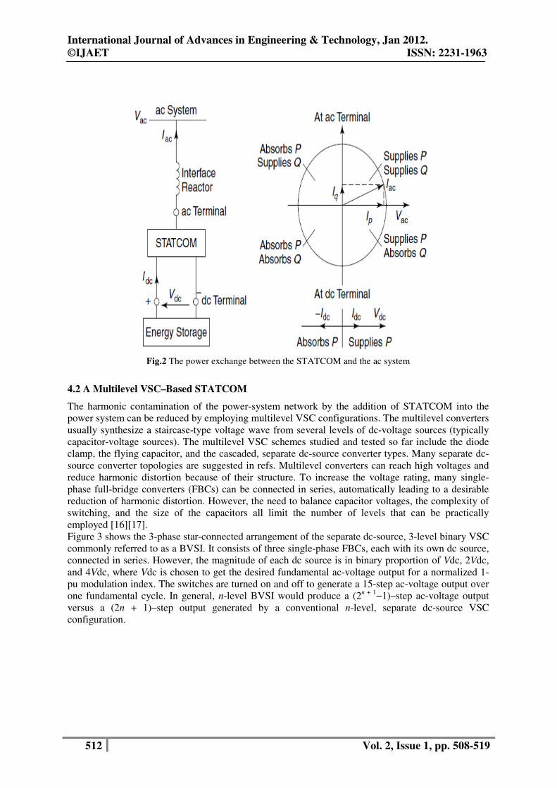
A STATCOM is a controlled reactive-power source. It provides the desired reactive-power generation and absorption entirely by means of electronic processing of the voltage and current waveforms in a voltage-source converter (VSC) [7]. A STATCOM is seen as an adjustable voltage source behind a reactance—meaning that capacitor banks and shunt reactors are not needed for reactive-power generation and absorption, thereby giving a STATCOM a compact design, or small footprint, as well as low noise and low magnetic impact. The exchange of reactive power between the converter and the ac system can be controlled by varying the amplitude of the 3-phase output voltage, Vs, of the converter. That is, if the amplitude of the output voltage is increased above that of the utility bus voltage, Vt, then a current flows through the reactance from the converter to the ac system and the converter generates capacitive-reactive power for the ac system. If the amplitude of the output voltage is decreased below the utility bus voltage, then the current flows from the ac system to the converter and the converter absorbs inductive-reactive power from the ac system. If the output voltage equals the ac system voltage, the reactive-power exchange becomes zero, in which case the STATCOM is said to be in a floating state. Adjusting the phase shift between the converter-output voltage and the ac system voltage can similarly control real-power exchange between the converter and the ac system. In other words, the converter can supply real power to the ac system from its dc energy storage if the converter-output voltage is made to lead the ac-system voltage. On the other hand, it can absorb real power from the ac system for the dc system if its voltage lags behind the ac-system voltage. A STATCOM provides the desired reactive power by exchanging the instantaneous reactive power among the phases of the ac system. The mechanism by which the converter internally generates and/ or absorbs the reactive power can be understood by considering the relationship between the output and input powers of the converter. The converter switches connect the dc-input circuit directly to the ac-output circuit. Thus the net instantaneous power at the ac output terminals must always be equal to the net instantaneous power at the dc-input terminals (neglecting losses)[8][9]. Although reactive power is generated internally by the action of converter switches, a dc capacitor must still be connected across the input terminals of the converter. The primary need for the capacitor is to provide a circulating-current path as well as a voltage source. The magnitude of the capacitor is chosen so that the dc voltage across its terminals remains fairly constant to prevent it from contributing to the ripples in the dc current. The VSC-output voltage is in the form of a staircase wave into which smooth sinusoidal current from the ac system is drawn, resulting in slight fluctuations in the output power of the converter [10]. However, to not violate the instantaneous power-equality constraint at its input and output terminals, the converter must draw a fluctuating current from its dc source. Depending on the converter configuration employed, it is possible to calculate the minimum capacitance required to meet the system requirements, such as ripple limits on the dc voltage and the rated-reactive power support needed by the ac system.
International Journal of Advances in Engineering & Technology, Jan 2012.
©IJAET ISSN: 2231-1963
512 Vol. 2, Issue 1, pp. 508-519
Fig.2 The power exchange between the STATCOM and the ac system
4.2 A Multilevel VSC–Based STATCOM
The harmonic contamination of the power-system network by the addition of STATCOM into the power system can be reduced by employing multilevel VSC configurations. The multilevel converters usually synthesize a staircase-type voltage wave from several levels of dc-voltage sources (typically capacitor-voltage sources). The multilevel VSC schemes studied and tested so far include the diode clamp, the flying capacitor, and the cascaded, separate dc-source converter types. Many separate dc-source converter topologies are suggested in refs. Multilevel converters can reach high voltages and reduce harmonic distortion because of their structure. To increase the voltage rating, many single-phase full-bridge converters (FBCs) can be connected in series, automatically leading to a desirable reduction of harmonic distortion. However, the need to balance capacitor voltages, the complexity of switching, and the size of the capacitors all limit the number of levels that can be practically employed [16][17]. Figure 3 shows the 3-phase star-connected arrangement of the separate dc-source, 3-level binary VSC commonly referred to as a BVSI. It consists of three single-phase FBCs, each with its own dc source, connected in series. However, the magnitude of each dc source is in binary proportion of Vdc, 2Vdc, and 4Vdc, where Vdc is chosen to get the desired fundamental ac-voltage output for a normalized 1-pu modulation index. The switches are turned on and off to generate a 15-step ac-voltage output over one fundamental cycle. In general, n-level BVSI would produce a (2n + 1−1)–step ac-voltage output versus a (2n + 1)–step output generated by a conventional n-level, separate dc-source VSC configuration.

International Journal of Advances in Engineering & Technology, Jan 2012.
©IJAET ISSN: 2231-1963
513 Vol. 2, Issue 1, pp. 508-519
Fig 3 The 3-phase, star-connected 3-level VSI
The multilevel converters usually synthesize a staircase-type voltage wave from several levels of dc-voltage sources (typically capacitor-voltage sources). The multilevel VSC schemes studied and tested so far include the diode clamp, the flying capacitor, and the cascaded, separate dc-source converter types. Many separate dc-source converter topologies are suggested in refs. Multilevel converters can reach high voltages and reduce harmonic distortion because of their structure. To increase the voltage rating, many single-phase full-bridge converters (FBCs) can be connected in series, automatically leading to a desirable reduction of harmonic distortion. However, the need to balance capacitor voltages, the complexity of switching, and the size of the capacitors all limit the number of levels that can be practically employed [7].
V. CONTROL STRATEGY
Active- and Reactive-Power Controls
The control strategy that is proposed in this paper regulates a generic single-phase cascaded H-bridge multilevel converter, which is composed of N H-bridges that are connected in series. The connection of the STATCOM device to the power grid is made using a coupling inductance. Assume that the grid voltage and output-current expressions are equal to the following:
vGrid = √2 VGrid .. Cos (ώt) (1)
if =√2 If . Cos (ώt-Ø) (2)
The expressions of the active and reactive powers that are supplied by the STATCOM to the grid are the following
PTOTAL = VGrid . If . Cos (Ø) (3) QTOTAL = VGrid . If . Sin (Ø) (4)
Where ϕ is the angle between the grid voltage and the current that is injected by the STATCOM. The active power is proportional to the current component which is in phase with the grid voltage (active component), and the reactive power is proportional to the current component which is orthogonal to the grid voltage (reactive component). Therefore, for active-power regulation, the active component of the current is changed, and on the other hand, for reactive-power regulation, the reactive component is modified. From these two current components, the instantaneous current reference could be generated.

International Journal of Advances in Engineering & Technology, Jan 2012.
©IJAET ISSN: 2231-1963
514 Vol. 2, Issue 1, pp. 508-519
The reactive-power reference is obtained from the dc-bus voltage control loops. If the dc-bus voltage of one of the shunt-connected H-bridges is lower than the reference voltage, it means that the reactive power should be provided to this H-bridge; therefore, the capacitor would take energy, which would increase the voltage level. On the other hand, if the dc-bus voltage is higher than the voltage reference, energy should be taken out of the bus capacitor. In this way, the output of each dc-bus voltage regulator is a particular reactive-power reference for each H-bridge.
VI. SIMULATION RESULTS
To verify the performance of the proposed cascade Three phase five level inverter is implemented as STATCOM with phase shifted bipolar sinusoidal PWM as control algorithm.Simulation have been carried out using Matlab–Simulink. In this paper, a simulation block set in Simulink/matlab was implemented as shown in fig 4 and the results are presented. In this model initially load1 (50KW, 15 KVAR) is supplied with 415V. After a period of 2 cycles another load2 (30KW, 10KVAR) is added with the help of circuit breaker. A five level inverter is connected as STATCOM. The control signal for this STATCOM taken from a closed loop POD technique. In this technique load voltage is always compared with reference voltage, whenever a deviation in the load voltage an error signal generated in the form of sine wave and this sine wave is used as reference signal in POD technique. Hence this control system produces necessary control signals for STATCOM to compensate the load voltage and reactive power requirement of the system.
Fig.4 Simulation Diagram of MLI as STATCOM 1

International Journal of Advances in Engineering & Technology, Jan 2012.
©IJAET ISSN: 2231-1963
515 Vol. 2, Issue 1, pp. 508-519
Fig.5 Source Voltage and Source Current 1
Fig. 6 Error voltage generator 1
International Journal of Advances in Engineering & Technology, Jan 2012.
©IJAET ISSN: 2231-1963
516 Vol. 2, Issue 1, pp. 508-519
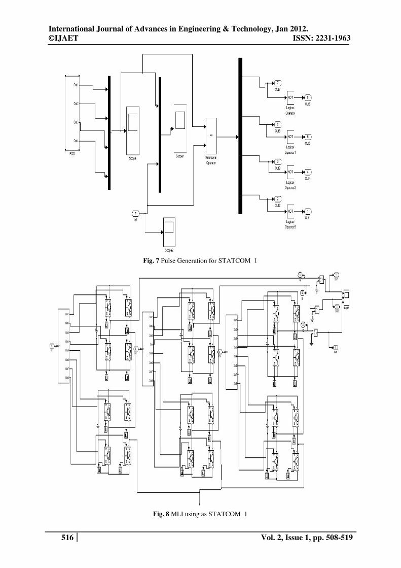
Fig. 7 Pulse Generation for STATCOM 1
Fig. 8 MLI using as STATCOM 1

International Journal of Advances in Engineering & Technology, Jan 2012.
©IJAET ISSN: 2231-1963
517 Vol. 2, Issue 1, pp. 508-519
Fig. 9 STATCOM output voltage 1
Fig10 Load Voltage and Current 1
Fig. 11 Load Active and reactive Powers 1

International Journal of Advances in Engineering & Technology, Jan 2012.
©IJAET ISSN: 2231-1963
518 Vol. 2, Issue 1, pp. 508-519
Fig 5 shows the balanced voltage and current supplying from the source. In fig 6 error signal generator has been shown. Fig 7 represents pulse generation for STATCOM based on the error signal. Fig 10 indicates the output voltage which clearly shows even after adding a load after two cycles it maintains a constant voltage where as a change in output current Fig 11 shows load active and reactive power when MLI acting as STATCOM.
VII. CONCLUSION
In this paper cascade five level inverter is implemented as STATCOM with star configuration for medium-voltage applications. The control algorithm is based on the “POD” type Multicarrier PWM. The control arrangement results from giving priority to the voltage-balancing control and reactive power balancing control. This model is mainly concentrated on unbalanced and continuously varying loads. Whenever there is a change in load this control arrangement of STATCOM able to balance the voltage and compensate the required reactive power. A 415V supply is given to the varying unbalanced load and a cascade number of N = 2 have verified the ability and effectiveness of the Reactive Power compensation.
REFERENCES
[1] Hirofumi Akagi, Fellow, IEEE, Shigenori Inoue, Member, IEEE, and Tsurugi Yoshii “Control and Performance of a Transformerless Cascade PWM STATCOM With Star Configuration” IEEE Transactions on Industry Applications, Vol. 43, No. 4, July/August 2007 [2] Ben-Sheng Chen and Yuan-Yih Hsu, Senior Member, “A Minimal Harmonic Controller for a STATCOM” IEEE Transactions On Industrial Electronics, Vol. 55, No. 2, February 2008 [3] Qiang Song and Wenhua Liu, Member, IEEE “Control of a Cascade STATCOM With Star Configuration Under Unbalanced Conditions” IEEE Transactions On Power Electronics, Vol. 24, No. 1, January 2009 [4] Chien-Hung Liu and Yuan-Yih Hsu, Senior Member, IEEE “Design of a Self-Tuning PI Controller for a STATCOM Using Particle Swarm Optimization” IEEE Transactions On Industrial Electronics, Vol. 57, No. 2, February 2010 [5] Bo˘stjan Bla˘zi˘c, Student Member, IEEE, and Igor Papi˘c, Member, IEEE “Improved D-StatCom Control for Operation With Unbalanced Currents and Voltages” IEEE Transactions On Power Delivery, Vol. 21, No. 1, January 2006 [6] Jon Andoni Barrena, Student Member, IEEE, Luis Marroyo, Member, IEEE, Miguel Ángel Rodríguez Vidal, Member, IEEE, and José Ramón Torrealday Apraiz “Individual Voltage Balancing Strategy for PWM Cascaded H-Bridge Converter-Based STATCOM” IEEE Transactions On Industrial Electronics, Vol. 55, No. 1, January 2008 [7] Fang Zheng Peng, Senior Member, IEEE “A Generalized Multilevel Inverter Topology with Self Voltage Balancing” IEEE Transactions On Industry Applications, Vol. 37, No. 2, March/April 2001 [8] Jianye Chen, shan song and Zanji Wang “Analysis and Implement of Thyristor-based STATCOM” International Conference On Power System Technology 2006 [9] Chong Han, Member, IEEE, Zhanoning Yang, Bin Chen, Alex Q. Huang, Fellow, IEEE, Bin Zhang, Student Member, IEEE, Michael R. Ingram, Senior Member, IEEE, and Abdel-Aty Edris, Senior Member, IEEE “ Evaluation of Cascade-Multilevel-Converter-Based STATCOM for Arc Furnace Flicker Mitigation” IEEE Transactions On Industry Applications, Vol. 43, No. 2, March/April 2007 [10] Kuang Li, Jinjun Liu, Zhaoan Wang, and Biao Wei “Strategies and Operating Point Optimization of STATCOM Control for Voltage Unbalance Mitigation in Three-Phase Three-Wire Systems” IEEE Transactions On Power Delivery, Vol. 22, No. 1, January 2007 [11] C. K. Lee, Joseph S. K. Leung, Member, IEEE, S. Y. Ron Hui, Fellow, IEEE, and Henry Shu-Hung Chung, Member, IEEE “ Circuit-Level Comparison of STATCOM Technologies” IEEE Transactions On Power Electronics, Vol. 18, No. 4, July 2003 [12] Diego Soto, Member, IEEE, and Rubén Peña, Member, IEEE “Nonlinear Control Strategies for Cascaded Multilevel STATCOMs” IEEE Transactions On Power Delivery, Vol. 19, No. 4, October 2004 [13] Y. Chen, B. Mwinyiwiwa, Z.Wolanski, and B.-T. Ooi, “Regulating and qualizing dc capacitance voltages in multi-level STATCOM,” IEEE Trans. Power Del., vol. 12, no. 2, pp. 901–907, Apr. 1997. [14] Y. H. Liu, J. Arrillaga, and N. R.Watson, “Multi-level voltage reinjection—A new concept in high power voltage source conversion,” Proc. Gen. Transm. Distrib., vol. 151, no. 3, pp. 290–298, 2004. [15] Y. H. Liu, J. Arrillaga, and N. R. Watson, “A new STATCOM configuration using multi-level dc voltage reinjection for high power applications,” IEEE Trans. Power Del., vol. 19, no. 4, pp. 1828–1834, Oct. 2004.

International Journal of Advances in Engineering & Technology, Jan 2012.
©IJAET ISSN: 2231-1963
519 Vol. 2, Issue 1, pp. 508-519
[16] Y. H. Liu, J. Arrillaga, and N. R.Watson, “Cascaded H-bridge voltage reinjection-Part II: Application to HVDC transmission,” Companion Paper. [17] Y. H. Liu, J. Arrillaga, and N. R.Watson, “STATCOM performance of a multi-level voltage reinjection converter,” presented at the IEEE/Power Eng. Soc. Transmission Distribution Conf., Dalian, China, 2005.
Authors M. Vishnu Prasad was born in Andhra Pradesh, India, received the B.Tech Electrical and Electronics Engineering from Dr. Paul Raj Engineering college affiliated to JNT University, Hyderabad in the year 2007 and M.Tech .Power Electronics & Drives from SRM University, India in the year 2010. Currently, he is interested to research topics include Power Electronics especially in multi level inverters. He is currently as a Lecturer of Electrical Electronics Engineering Department at Sri Vasavi Institute of Engg & Technology, Nandamuru, Pedana Mandal, Krishna (Dt) Affiliated to JNT University, Kakinada, Andhra Pradesh, India K. Surya Suresh was born in Andhra Pradesh, India, received the B.Tech Electrical and Electronics Engineering from Sri Sarathi institute of Engg & Technology affiliated to JNT University, Hyderabad and M.Tech .Power Electronics as concentration from KL University, India. Currently, he is interested to research topics include Power Electronics, multi level inverters and fuzzy logic controllers. He is currently as a Lecturer of Electrical Electronics Engineering Department at Sri Vasavi Institute of Engg & Technology, Nandamuru, Pedana Mandal, Krishna (Dt) Affiliated to JNT University, Kakinada, Andhra Pradesh, India