Control and Monitoring of Buildings Foundation ... · Control and monitoring of buildings...
21
TS 78 – Survey Control and Monitoring Building Dr. Andréa de Seixas, Eng. José Roberto de Seixas, Prof. José Jorge de Seixas Control and monitoring of buildings foundation – Applications in very high buildings structure Shaping the Change XXIII FIG Congress Munich, Germany, October 8-13, 2006 1/21 Control and Monitoring of Buildings Foundation - Applications in Very High Buildings Structure Andréa DE SEIXAS, Brazil José Roberto DE SEIXAS, Brazil José Jorge DE SEIXAS, Brazil Key words: Control and monitoring of buildings foundation - Applications in very high buildings structure. SUMMARY The analysis of the foundation behavior requires the study of the interaction between the concrete structure and the ground. The control and the monitoring of foundations can be restricted the measurement of settlements and displacements. Thus being, the confirmation of the quality of executed foundations already comes to still more stimulate the job of geodesic technologies in civil constructions, situations these, still rare in Brazil, thus breaching, of a form or another one unconsciously, the fear of the impact, on the part of the constructors, the installation of instruments of measurement in this area. Accidents come being, each time more, detected in urban environments, as it is the case of the Metropolitan Region of Recife (PE), where are well-known that the almost uncontrolled development of civil constructions are predominantly neglected, aggravated by the soil quality. The land on which they will fall again future projected loads, becomes element inquiry key, therefore exactly after the laboratory and field assays it remains the doubt how much to its behavior. For its diagnosis a perfect interaction is necessary enters the soil prospect company, the designer, the contractor and the consultants. Similar by that during the execution of the civil construction basic decisions for the perfect harmony can be taken between what was projected and the area of the construction, which will support the same. The necessity is then in following the execution of the workmanship after the accomplishment of the foundation and to investigate if its behavior is as foreseen theoretically inside of a permissible limit of deformation from the measurement of its settlements and displacement. For this the methods are excellent technician of Geodesy applied to engineering to subsidize the distributed point-object measurements in the study area. This work has as objective to introduce important concepts of Geodesy, in the related civil constructions in direct foundations. It will be presented, moreover, through a real case a methodology procedure destined for the control and monitoring of foundations, searching its appropriate solutions in the large buildings during the phase of construction or in problematic problems in the ones already constructed.
Transcript of Control and Monitoring of Buildings Foundation ... · Control and monitoring of buildings...

TS 78 – Survey Control and Monitoring Building Dr. Andréa de Seixas, Eng. José Roberto de Seixas, Prof. José Jorge de Seixas Control and monitoring of buildings foundation – Applications in very high buildings structure Shaping the Change XXIII FIG Congress Munich, Germany, October 8-13, 2006
1/21
Control and Monitoring of Buildings Foundation - Applications in Very High Buildings Structure
Andréa DE SEIXAS, Brazil
José Roberto DE SEIXAS, Brazil José Jorge DE SEIXAS, Brazil
Key words: Control and monitoring of buildings foundation - Applications in very high buildings structure. SUMMARY The analysis of the foundation behavior requires the study of the interaction between the concrete structure and the ground. The control and the monitoring of foundations can be restricted the measurement of settlements and displacements. Thus being, the confirmation of the quality of executed foundations already comes to still more stimulate the job of geodesic technologies in civil constructions, situations these, still rare in Brazil, thus breaching, of a form or another one unconsciously, the fear of the impact, on the part of the constructors, the installation of instruments of measurement in this area. Accidents come being, each time more, detected in urban environments, as it is the case of the Metropolitan Region of Recife (PE), where are well-known that the almost uncontrolled development of civil constructions are predominantly neglected, aggravated by the soil quality. The land on which they will fall again future projected loads, becomes element inquiry key, therefore exactly after the laboratory and field assays it remains the doubt how much to its behavior. For its diagnosis a perfect interaction is necessary enters the soil prospect company, the designer, the contractor and the consultants. Similar by that during the execution of the civil construction basic decisions for the perfect harmony can be taken between what was projected and the area of the construction, which will support the same. The necessity is then in following the execution of the workmanship after the accomplishment of the foundation and to investigate if its behavior is as foreseen theoretically inside of a permissible limit of deformation from the measurement of its settlements and displacement. For this the methods are excellent technician of Geodesy applied to engineering to subsidize the distributed point-object measurements in the study area. This work has as objective to introduce important concepts of Geodesy, in the related civil constructions in direct foundations. It will be presented, moreover, through a real case a methodology procedure destined for the control and monitoring of foundations, searching its appropriate solutions in the large buildings during the phase of construction or in problematic problems in the ones already constructed.

TS 78 – Survey Control and Monitoring Building Dr. Andréa de Seixas, Eng. José Roberto de Seixas, Prof. José Jorge de Seixas Control and monitoring of buildings foundation – Applications in very high buildings structure Shaping the Change XXIII FIG Congress Munich, Germany, October 8-13, 2006
2/21
Control and Monitoring of Buildings Foundation - Applications in Very High Buildings Structure
Andréa DE SEIXAS, Brazil
José Roberto DE SEIXAS, Brazil José Jorge DE SEIXAS, Brazil
1. INTRODUCTION The verification of the behavior of foundations requires the study of the interaction between the concrete structure and the ground. The control and the monitoring of foundations can be restricted the measurement of settlements and displacements. This work has the objective, amongst others, to emphasize the importance of the control of performance of the buildings structure and the foundations from the monitoring control of the settlements applied the large buildings during the phase of construction or in the ones already constructed. Accidents (landslide, collapse, subsidence of the ground, as well as displacement) come being, each time more, detected in urban environments, as it is the case of the metropolitan region of Recife (PE), where are well-known that the almost uncontrolled development of large buildings constructions, aggravated by the ground quality. The confirmation of the quality of executed foundations already comes to still more stimulate the job of geodesic technologies in the constructions area, situations these still rare in Brazil, thus breaching, of a form or another one, unconsciously, the fear of the impact, on the part of the constructors, the installation of instruments of measurement in this region. Not more than than Geodesic Sciences in the branch of the Geodesy Applied to Engineering to subsidize the measurements of reference points and points-object distributed in the area of study by means of an instrument and adequate methods of survey. From the analysis and of the comments of field in geodesic structures, as reference to the object positioning necessary, similar of that the vertical displacements can be studied, searching more appropriate solutions for the stability of the constructions. The study of the foundations it was divided in four phases: prospect, project, choice of the foundation and execution. The interaction between superstructure and foundation has as consequence vertical displacements, that is, deformations. No matter how hard good inquiries and made samplings of good quality are executed, it will always have possibilities of “geologic surprises”, measurable behaviors not total foreseen and variability not fully measurable “a priori”. The necessity is then in following the execution of the workmanship after the accomplishment of the foundation and to investigate if its behavior is as foreseen theoretically inside of a permissible limit of deformation from the measurement of settlements in field. The ground on which they will fall again future projected loads, becomes element inquiry key, therefore exactly after the laboratory and field assays it remains the doubt how much to its behavior. For its diagnosis a perfect interaction is necessary enters the prospect company, the designer, the contractor and the consultants. Similar by that during the execution of the workmanship
TS 78 – Survey Control and Monitoring Building Dr. Andréa de Seixas, Eng. José Roberto de Seixas, Prof. José Jorge de Seixas Control and monitoring of buildings foundation – Applications in very high buildings structure Shaping the Change XXIII FIG Congress Munich, Germany, October 8-13, 2006
3/21
basic decisions for the perfect harmony can be taken between what was projected and the area of the construction, which will support the same. The measurement of settlements in such a way allows the inquiry of the foundation how much of the building structure. The dimensions measured then will be collated with esteemed settlements. During the construction the presence of cracks in the structures not yet harmful to the stability of the building could be noticed. Is standed out here the importance of the systematic accompaniment of the workmanship with the objective to guarantee the security against its rupture. As objective of the measurement of vertical displacements, it is standed out:
- To confirm the quality of finished foundations; - To control settlement of the buildings structure; - To verify the conditions and to evaluate the capacity of foundations of existing
buildings when if to treat to remodel the same ones, to modify the same ones or to use to advantage the same foundations for other ends;
- To verify the conditions and to evaluate the capacity of foundations of buildings already constructed and neighboring to other workmanships of construction;
- To study the stability of the foundation and the buildings structure from the behavior of accomplishing set of points-object of the foundation and the building structure; beyond
- To assure the housing or to define an area of imminence of rupture risk.
The definition of a System of Reference from a System of Coordinates and a set of points is of basic importance for the analysis of the measurement and the monitoring of the workmanship with respect to the vertical displacement. In this context, it will be approached the base of a study of case executed on direct foundations, methods for the control of the foundation, monitoring of the foundation, beyond the presentation of excellent results on the object of study in question. 2. BASIC CONCEPTS The Foundation is the System formed for the set of isolated elements (stakes) and the mass of the ground (Aoki, N., 2006). All civil workmanship is subjects the actions of the environment for this reason, must be considered all the variability of the ground having the isolated elements of foundation, such as the stakes. To understand the results of this work it is necessary the description of some criteria of measures and the conceptualization of: vertical displacement, permissible settlement, total settlement, partial settlement, speed of settlements and angular distortion.
Vertical displacement The vertical displacement is a deformation suffered in the object or for the object (when it is about the variation loading) in the vertical direction. When the direction of the displacement is for low, says that it had one settlement in the structure or subsidence depending on the size of the displacement. When the direction of the displacement is for top, says that it had a lifting. For convention the signal of the low vertical displacement as positive is adopted.
TS 78 – Survey Control and Monitoring Building Dr. Andréa de Seixas, Eng. José Roberto de Seixas, Prof. José Jorge de Seixas Control and monitoring of buildings foundation – Applications in very high buildings structure Shaping the Change XXIII FIG Congress Munich, Germany, October 8-13, 2006
4/21
The analysis of vertical displacements of the study area as a whole is possible, when the altimetry points are linked between itself by means of the transport of heights of one determined fixed altimetry referential.
Permissible settlements When applying load in a direct foundation, inevitably will occur settlements that, in general, they are of the order of few sets of ten of millimeters, but that the hundreds can even arrive and until, exceptionally, thousand of millimeters. Thus hypothesis of fixed support pillars, generally, made in the structural calculation, is a mere fiction (Cintra, J.C.A, et. al., 2003). It is defined settlements, of a footing for example, as being the vertical displacement, for low, of base of the footing in relation to not deformable. This displacement is resultant of the deformation of the ground (reduction of volume and/or change of form). The settlements can be classified in: absolute settlement or total settlement (ρ) of footing and differential settlement (δ) between two footings beyond the angular distortion or specific differential settlement (δ/l), in general l is in the distance between footing. In result settlement, the building can suffer vertical motion (translation) followed or not from inclination (rotation). High absolute settlement, but of same order of magnitude in all the parts of the foundation, generally can be tolerated, therefore the differential settlements is that they are preoccupying. However, the differential settlements normally are bigger when the absolute settlements are bigger. Therefore the magnitude of the absolute settlement can be accepted as an indirect measure for the differential settlement.
Tolerance Settlements
In accordance with NBR 6122/96, the permissible tension and the permissible load depend on the sensitivity of the projected construction to the settlement, especially the specific differential settlements (or angular distortion), which generally are the ones that can harm its stability or functionality.
Total and partial settlements
The total settlement (accumulated settlement) is defined by the descending vertical displacement of a foundation element. The concept of permissible settlements, at least for the building, is intimately linked on to the tradition of the community. The permissible values are fixed by the involved specialists with the project, the execution and the accompaniment of the performance of the workmanship. Its values elapse of the local experience throughout periods that allow to conclude that, for those types of structures, with those loadings, in those types of ground and in those communities, such values of settlements can be considered acceptable, and, therefore, permissible. The partial settlement is defined as the difference enters the heights of two consecutive measurements of one same point. The illustrative heading we can cite three criteria of studious authors and of the mechanics of soil. The Russian norm - Polshin, D.E. Tokar, R. A. - 4th ICSMFE - 1957, that it considers for total settlement permissible for structures porch the value of 100mm. Already Sowers, G.F. -

TS 78 – Survey Control and Monitoring Building Dr. Andréa de Seixas, Eng. José Roberto de Seixas, Prof. José Jorge de Seixas Control and monitoring of buildings foundation – Applications in very high buildings structure Shaping the Change XXIII FIG Congress Munich, Germany, October 8-13, 2006
5/21
1962 the value between 50mm and 100mm and according to MacDonald D.H.; Skempton, A.W. - ICA - London - 1955 consider for isolated foundation in compact sand the value of 51mm, being the value more recommended of 38mm. In the same way in accordance with Teixeira and Godoy (1996), “theoretically, a structure that suffered uniform settlements would not suffer damages, exactly for values exaggerated of total settlement. In the practical one, however, the occurrence of uniform settlement does not happen, having always decurrently differentials settlement of some type of loads eccentricity, or heterogeneities of ground, a limitation of total settlement is one in the ways to limit differential settlement. For usual structures of steel or concrete, Burlland et al. (1977) they consider acceptable as values-limit, in routine cases, following recommendation of Skempton- MacDonald for values of differential settlements and total settlement is limited:
Sand: δmax =25mm (maximum differential settlement) ρmax= 40mm for isolated footings (maximum absolute settlement) ρmax= 40mm to 65mm for radiate Clay: δmax =40mm ρmax =65mm for isolated footings ρmax=65mm to100mm for radiate
Teixeira and Godoy (1996) call the attention for the fact of that “these values do not apply to the case of buildings in structural brick masonry, for which the criteria must be more rigorous.” They add that “is important to know to distinguish the repeatedly cases from those that require criterions analysis of the problem of the settlement (high buildings with bodies of different heights, great vain, special beams of the great inertia, special finishing, etc)”. The actual damages for reason of foundations are grouped by Skempton and MacDonald, apud Teixeira and Godoy (1996), in three main categories:
• Damages architectural, or the visual appearance of the construction. They are those visible ones to the common observer, causing some type of discomfort: cracks in walls, settlement of floors, put out of plumb of buildings, amongst others. • Damages to the functionality, or to the use of the construction. Put out of plumb of a building can cause problems of extreme consuming of elevators and invert declivities of floors and pipelines or even to breach pipelines, to harm the access, amongst others. The differential settlements can cause the binding of doors and windows, to also cause cracks for where can pass humidity. • Structural damages. They are those caused to the structure properly said, being able to compromise its stability.

TS 78 – Survey Control and Monitoring Building Dr. Andréa de Seixas, Eng. José Roberto de Seixas, Prof. José Jorge de Seixas Control and monitoring of buildings foundation – Applications in very high buildings structure Shaping the Change XXIII FIG Congress Munich, Germany, October 8-13, 2006
6/21
Speed of settlement For the control and monitoring of vertical displacement, the speed of settlement in μ/day is another indispensable parameter for the study of the behavior of the displacement. In the definite cases as ˝normal˝, they have as speed control the following criterion:
• Building in construction and supported in low flat foundation can be considered normal when they present speed until 200µ ⁄ day.
• Will have been supported in deep foundations, this speed will have to be reduced for 100µ ⁄ day.
However these values could be bigger, temporarily, due to external factors to the workmanship, as for example water sheet degradation, excavations next deep ditches to the workmanship, and action of negative friction in stakes, among others. In constructed buildings more than the 5 years and considered stabilized is common to register settlements speed lower than 20μ ⁄ day. In these same buildings, speeds between 20μ/day and 40μ ⁄day are considered of moderate, the high ones and above of 40μ ⁄day are considered very high, and therefore, very preoccupying.
Angular distortion
On the basis of observations of about a hundred of buildings, Skempton-Macdonald, in 1956, had associated the tolerance of damages with value-limit for the angular distortion δ/l, where δ is the differential settlement between two pillars and l the distance between them. Many others important publications if had followed, as, for example, of Bjerrum (1963), apud Morais Ferreira (1976). In summary, Burland et. al. (1977) they detach the following boundary-values of Skempton-Macdonald:
δ/l = 1/500 safe limit for buildings for which the appearance of fictions is not allowed δ/l = 1:300 cracks in walls of buildings δ/l = 1:150 - structural damages in beams and columns of current buildings
In the relations of this type they must be taken with caution, therefore the angular distortion must depend on some factors, such as: type and characteristics of the ground, type of the foundation, port, tension and rigidity of the superstructure and properties of the employed materials. Moreover, the occurrence of stresses provokes the redistribution of efforts in the superstructure, what it modifies settlements and, thus, interactively, what it constitutes the call interaction structure-ground. For the calculation of the angular distortion between two pillars any are necessary the distance and differential settlement between the same ones. The differential settlement is given by the difference between the accumulated settlements of the two respective pillars. Thus,
Ä = δ ⁄ l. Where: Ä - angular distortion, δ - differential settlement and l distance
between them pillars.
TS 78 – Survey Control and Monitoring Building Dr. Andréa de Seixas, Eng. José Roberto de Seixas, Prof. José Jorge de Seixas Control and monitoring of buildings foundation – Applications in very high buildings structure Shaping the Change XXIII FIG Congress Munich, Germany, October 8-13, 2006
7/21
3. FOUNDATIONS OF BUILDING 3.1 Buildings structure of great vertical size The structure is considered of great vertical size when its vertical length predominates in detriment of its horizontal length. As examples of structures of great vertical size it can be cited: apartment and commercial buildings (approached in the context of this work), aeolian towers, communication towers, derricks, pillars of bridges, trees (example: sequoias), amongst others. The element key for the stability and security of these structures is the foundation, being in this way the interface between a vertical structure and the ground. It is standed out here that in the Metropolitan Region of Recife (RMR) the register in cadastre of property with predominance in the vertical direction still is devoid of investigation in descriptive and geometric, for example: which the buildings, how many floors exist and where they are located in the geographic space of the Metropolitan Region. Is well-known the constructions of buildings with composed structures of 20 to 45 floors, considered in this work as structures of great vertical size. The absence of a referring practical material to the methodology for geodesic studies of vertical motion by means of optic procedures of measurement, from a study of real case, located in urban area, comes to stimulate the accomplishment of this work. In these urban areas two score points characteristic are observed:
- the first one, the present diversity of types of soil; - the second, expressive presence of an agglomeration of buildings structure of
great vertical size. The accomplishment of studies of these vertical motions will only be materialized from the physical establishment of defining fixed points of an altimetry referential of the Bench Mark type (BM), in the immediacy of the building structures. The analyzed construction is constituted by a porch structure of reinforced concrete with 23 (twenty and three) floors (floor garage, floor for parties, 20 floors types and coverage). It does not have underground projected. There are in the blade a total of 26 (twenty and six) pillars, with permanent loads varying of 74Tf to 464Tf (740KN to 4640KN). It has vertical, horizontal load indication and moments due the action of the wind. In the periphery, it has a total of 32 (thirty and two) pillars, with permanent load varying of 6,0Tf to 42,0Tf (60KN to 420KN). The average pressure transmitted by floor is of 9,0KN/m ².
3.2 Specifications of the project of foundations of the building Portal do Rosarinho1
From a real case involving direct foundations (superficial) the phases of the study of the foundations will be defined.
1 Client: Condomínio do Edifício Portal do Rosarinho Obra: Edifício Portal do Rosarinho Local: Rua Julião Neto,371 – Encruzilhada, Recife – PE Brasil Data do Projeto de Fundações: 07 de fevereiro de 2003
TS 78 – Survey Control and Monitoring Building Dr. Andréa de Seixas, Eng. José Roberto de Seixas, Prof. José Jorge de Seixas Control and monitoring of buildings foundation – Applications in very high buildings structure Shaping the Change XXIII FIG Congress Munich, Germany, October 8-13, 2006
8/21
I. Main Blade
In virtue of the granular (coarse/fine) characteristics and compacted of the foundation soil the solution was evaluated in superficial foundation with improvement through columns of compacting of sand and gravel. The solution of foundation in supported isolated and conjugated footings in the improved ground. The maximum permissible pressure in the ground, for sizing of the foundation, must be 40,00tf/m² (400,0KN/m²), considering permanent loads, being able to reach 52,0tf/m² (520KN/m²), when the additions will be considered due the action of the wind. The foundations will be seat in the height -1,80m in relation to the curb of the street Ceará. Esteem volume of concrete of: 236,0m³.
II. Improvement of the ground support of the Foundation
• This type of solution has been widely used in Recife and Aracaju, with sufficiently satisfactory results. The technique consists of the execution of a quadrangular mesh in whose knots are executed the compacting columns. In such a way the compacting is reached through three effect: displacement of material in the equal ground to the volume of the compacting column; introduction of compact additional material; and effect of the vibration due to the executive proceeding. Consequently, it has a profit of shear strength of the ground and a reduction in the level of deformations.
In this solution, it was admitted a square shaped mesh with side of 1,20m and columns of 400mm of diameter between the heights 0,00 and -7,00m in the initial phase of project, being later finished and executed through a square shaped mesh with 1,20m and columns of 300mm of diameter between the heights 0,00m and -7,00m.
• Eventually, the penetration of the pipe can be interrupted before the foreseen height (- 7,00m),
provided that the penetration energy reaches a minimum value of 80Tf.m for two consecutive stretches of 50cm.
a. It foresees an execution of a total of 635 columns of compacting of send and gravel with one mixes (trace) of 3:1 (send or dust of rock: gravel 50), in volume.
• The minimum diameter of the compacting columns will be of Ø=300mm. • The stretches between the compacting columns will be of 1,20m. • Meter of compacting column will have to be injected a minimum volume of 85,0 liters/m. • The fulfilling of the pipe with the material (send/gravel), will not have to reach bigger height of
1,00m so that if it prevents significant loss of the compacting energy of this material in the interior of the pipe.
• From the height of foundation (- 1,80m) and until the final depths, the advance of the compacting pipe will have to be made by penetration.
The amount of compacting columns: 635
III. Materials for compacting
Sand: material injected for filling of the stretch where it desires, to produce the compacting. It will have to be clean, free of organic substance, without plasticity, granulated of thick average to gross, the proceeding one from natural deposit, alluvium, or torrent. As option, the sand could be substituted by rejects of quarry (rock dust), proceeding from the breaker of granite rock or another one of similar hardness. Gravel: mass material, contributes during the compacting, and for the rigidity of the layer as a whole. The granite rock breaker of or another one of similar hardness will have to be gotten of. The minimum diameter to be used will be Ø=50mm.

TS 78 – Survey Control and Monitoring Building Dr. Andréa de Seixas, Eng. José Roberto de Seixas, Prof. José Jorge de Seixas Control and monitoring of buildings foundation – Applications in very high buildings structure Shaping the Change XXIII FIG Congress Munich, Germany, October 8-13, 2006
9/21
IV. Equipment for compacting
• Vertical tower, electric drive or explosion, with double or triple tow-car, capacity of hoisting of at least 1400Kg.
• Internal diameter of the compacting pipe: Ø=300mm. • Length of the compacting pipe 7,50m. • Minimum weight of the compacting pylon: 1400Kg • Minimum diameter of the compacting pylon: 180mm • Height of fall of the pylon will have to be defined during the process, for better adjustment
energy/effectiveness.
V. Criteria of geotechnical control of the compacting Control in at least 40% (forty percent) of the total of the compacting columns, consisting of the following criteria will have to be effected:
• Diagram of penetration • Final energy of penetration • Diagram of compacting • Injected volume
VI. Periphery • The solution of foundation of pillars of the periphery consists of supported isolated footings bin the
natural ground. • The maximum permissible pressure in the ground, for sizing of the foundation, must be of 10,00Tf/m²
(100,0KN/m²). • The foundations will be seat in the height -1,80m.
VII. Notes of project • By the executed analysis the development is not waited of settlement harmful the structure, however, is
necessary the accompaniment of the evolution of settlement during the period of construction, through periodic measurements to each three concreted floors.
• The periphery structure will not be simultaneously constructed with main blade. • The execution of prospect is necessary during and after the execution of the improvement to guarantee
the used geotecnic parameters in the study.
VIII. Complementary notes
• The location of the pillars will have to be made by the structural project or the project architectural. • This work is based in the structural project of authorship of the Estrutura Engenharia Ltda. and in the
prospect of simple recognition the percussion report S-098/02 number of the Ensolo Ltda. and the foundation will be executed by the Copef C. Pereira Estacas e Fundações Ltda.
• All the height cited here are related to a point in the curb of the street Ceará (height=0,00) RN of the workmanship in the Pole number 13/1334.
TS 78 – Survey Control and Monitoring Building Dr. Andréa de Seixas, Eng. José Roberto de Seixas, Prof. José Jorge de Seixas Control and monitoring of buildings foundation – Applications in very high buildings structure Shaping the Change XXIII FIG Congress Munich, Germany, October 8-13, 2006
10/21
4. CONTROL AND MONITORING OF THE FOUNDATION OF BUILDINGS 4.1 Generalities The definition of the geometric model of the object is element key for the accomplishment of the monitoring. Situation this established at the beginning of the implantation of the pillars of the building edification. The amount of points and the distance between the same ones will have to be chosen, in way that the vertical displacement of the object can be determined, free of errors. Generally they are distinguished enters relative measurements of deformation (control of the relative position of an point-object with respect to another point-object) and absolute measurements of deformation (determination of the movements of the points-object with respect the fixed points (of reference) external or not in the work area (Kahmen, 1997). For the verification of vertical displacements, the knowledge of a situation of reference, settled through a called measurement of “measurement zero” is demanded. The measurement circumstances will go to define the choice of the method and the procedure of measurement. In accordance with the behavior of the vertical displacement each point-object could be observed continuously or discontinuously. When the relation cause-effect determined through a model of dynamic deformation (Moeser, et. al., 2000) previously is known, situation of this work, adopts a measurement of discontinuous deformation (discrete), contrary case is opted to a measurement of continuous deformation. 4.2 Definition of the System of Reference and the points-object field It is of great importance the analysis to the comments of field in geodesic structures as referential to the objects positioning necessary, similar of that they can be studied and be analyzed the different workmanships of engineering, as in the studies of the vertical displacements, making possible more appropriate solutions the stabilities of the building constructions. These structures are constituted by a field of reference points and by a point-object field (Silva, T.F et. al., 2004). 4.2.1 System of vertical reference A System of vertical reference in a workmanship of building construction is fixed through a surface of altimetry reference defined by a fictitious horizontal plan and its distance to a materialized altimetry fixed point called Reference of Level (RN). In the works related to Engineering this altimetry control point is defined as Bench Mark (BM), this type of materialization of the altimetry net is required when it involves works of high and/or highest precision. For its implantation in the place of the workmanship it is necessary a study of the different existing ground layers in this area. Its implantation is carried through by means of a metallic connecting rod penetrated until the layer most steady of the ground (Moeser et. al., 2000). In this work the reference surface is represented by a tangent horizontal plan to the Bench Mark, called of vertical reference “zero” of the workmanship. All the others heights of the study points-object field will be related to this fictitious horizontal plane of reference.

TS 78 – Survey Control and Monitoring Building Dr. Andréa de Seixas, Eng. José Roberto de Seixas, Prof. José Jorge de Seixas Control and monitoring of buildings foundation – Applications in very high buildings structure Shaping the Change XXIII FIG Congress Munich, Germany, October 8-13, 2006
11/21
4.2.2 Points-object field The points-object field defines the study object. The control and monitoring of the foundation of the building pass, then, to be investigated from the control and monitoring of the vertical displacement of these points-object determined throughout the execution of workmanship and related to a Local Vertical Reference System of the workmanship as described in the previous item. The measurement bolts (points-object) are defined in a System of Reference of the Object (De Seixas. et. al., 2001 and 2005). The points-object field is materialized in the structure of the pillar of the building construction. The Figure 3 (a) shows to the position of the respective pillars with respect the construction. For the determination of in the distance it enters them pillars of the workmanship was fixed the center of the P1 pillar as origin (0,0) of the System of Reference of the object of rectangular coordinates (X, Y). Axle X is defined by the direction of them pillars P1 and P11 and axle Y is defined by the direction of them pillars P1 and P2, in accordance with the plant of location of them pillars. The distances interpillars are necessary for the calculation of the defined angular distortion in item 2. In intention to reduce to the minimum the withdrawal and the new instrumentation of bolts of settlements in the building structure it is recommended the installation of these in appropriate faces of the structure of the pillar, having searched thus, optimization of the measurement during the development of the workmanship, has seen the presence of new situations of work in the survey area, imposed for the arrived production and of materials of the daily use of the construction.
4.3 Choice of the method and accomplishment of the measurement For the altimetry interconnection of the points-object the method of the classic geometric leveling will be used. With this method they are determined, through aimed at horizontal, the differences of height (unevenness) between points next one to the others (Kahmen, 1997). In the intended conception, the job of an optic level of high precision was become incorporated (Pentax - AFL - 320, nº. 113195). With readings carried through on one steel aiming inox of 2m, in millimeter and adapted for this work, considering appropriate atmospheric conditions for its use. The survey was executed from the altimetry referential defined by the Bench-Mark (see item 4.1). The geometric leveling was carried through by traverse around the workmanship, having involved different pillars. Being about .16 th Measurement of Control had been used 11 pillars (B.M. - P8 - P7 - P4 - P2 - P21B - P23 - P25 - P26 - P20 - P10aux - P10 - B.M.) as the Figure 3 (a). To perform a closed circuit in return to the Bench-Mark of approximately 170m. The measurements on level rod placed in those bolts of the respective pillars had been carried through concomitantly from the stations of the traverse for irradiation. 4.4 Processing and analysis of the data The heights of the bolts of settlement had been determined from the carried through readings, with due calculation of compensation and distribution of the errors used in the geometric leveling. The error of closing in the geometric leveling of high precision is of <=3mm(L)½,

TS 78 – Survey Control and Monitoring Building Dr. Andréa de Seixas, Eng. José Roberto de Seixas, Prof. José Jorge de Seixas Control and monitoring of buildings foundation – Applications in very high buildings structure Shaping the Change XXIII FIG Congress Munich, Germany, October 8-13, 2006
12/21
being L the perimeter of the circuit during the measurement in km [13133 NBR]. For bigger values of closing that this, sends regards a new survey. The new heights of the bolts and the respective height of reference are described in Tab.- 01. Being about the tenth seventh leveling of them pillars (columns) of the building, performing a total of 996 days (almost 3 years) of monitoring, determined the new heights of the respective bolts in relation to the reference defined for the Bench-Mark2. From these data they had been calculated: total settlements (accumulated settlements until .17 th reading), partial settlements (settlement enters the successive times of measurement (reading), the speeds of partial and total settlements and of respective pillars and its respective total accelerations, beyond the partial and total angular distortions. The graph of the operating loading in the foundation with the time and the graph of settlements with the time illustrate the behavior of the foundation of the beginning of the construction until the date of the last measurement. Results these demanded by NBR 6122/96. 5. RESULTS AND REPRESENTATIONS OF THE DATA In view of the volume of data generated during the 17 carried through readings, which composes the control and monitoring of the building structure now in study, the choice of a time of measurement became necessary to illustrate the carried through work. In this case were opted to the tenth seventh measurement. For the results and described representations below it must be considered that during the measurement of settlements had been added two new bolts in the faces of them pillars called P10 and P19 P10aux and P19N respectively, in virtue of the construction of the new deposit of material of construction under of the building. In the same way that pillars P19 and P26B had been eliminated two bolts of them.
2 The height of the Bench-Mark was adapted as igual to 0,00mm.

TS 78 – Survey Control and Monitoring Building Dr. Andréa de Seixas, Eng. José Roberto de Seixas, Prof. José Jorge de Seixas Control and monitoring of buildings foundation – Applications in very high buildings structure Shaping the Change XXIII FIG Congress Munich, Germany, October 8-13, 2006
13/21
5.1 Diagram of bars with the values of accumulated settlements of the respective pillars
Figure 1: Diagram of accumulated settlements
From figure 1 one concludes that: • Tracing a diagram of bars with the values of total settlement (accumulated), can be concluded that the
differential settlement of the building in construction is still admittedly, since most of the values is concentrated enters 19,25mm and 34,45mm (see item 2);
In the Tab.-01 following they are described the accumulated settlements, in millimeter, between the first one and tenth sixth and between first and the tenth seventh reading, determined with the leveling, the partial settlements, in millimeter, between the tenth sixth and tenth seventh reading.
Bolts of settlement
Date: 13/09/2003 14/09/2003
Date: 19/12 ⁄ 2005
Δ days 826
Date: 07 ⁄06⁄2006
Δ days 170
Δ days 996
Reading n°.01
Reading n°. 16
Accumulated settlement until 16th.
reading (mm)
Reading n°.17 Partial settlement
between L16 e L17
(mm)
Accumulated settlement until 17th. reading
(mm)
Reference height (mm)
Observed height (mm)
Observed height (mm)
1 471,90 452,65 19,25 451,35 1,30 20,55 2 442,60 419,85 22,75 417,80 2,05 24,80 3 442,60 418,00 24,60 416,10 1,90 26,50 4 451,30 424,50 26,80 422,45 2,05 28,85 5 472,70 443,65 29,05 441,50 2,15 31,20 6 468,90 440,15 28,75 438,15 2,00 30,75 7 457,10 427,30 29,80 425,50 1,80 31,60 8 431,50 398,95 32,55 397,05 1,90 34,45 9 472,60 440,80 31,80 439,20 1,60 33,40
10 448,00 418,00 30,00 416,23 1,77 31,77 10aux --------- 470,00 ------- 467,80 2,20 --------
11 459,30 441,70 17,60 440,05 1,65 19,25 12 456,20 432,40 23,80 430,70 1,70 25,50 13 455,50 429,05 26,45 427,20 1,85 28,30
Diagram of accumulated settlements
02468101214161820222426283032343638
1
Pillars
Acc
umul
ated
se
ttle
men
ts[m
m]
P1 P2 P3 P4 P5 P6 P7 P8
P9 P10 P11 P12 P13 P13B P14 P15
P16 P17 P18 P18B P19 P20 P21 P21B
P22 P23 P24 P25 P26 P26B

TS 78 – Survey Control and Monitoring Building Dr. Andréa de Seixas, Eng. José Roberto de Seixas, Prof. José Jorge de Seixas Control and monitoring of buildings foundation – Applications in very high buildings structure Shaping the Change XXIII FIG Congress Munich, Germany, October 8-13, 2006
14/21
13B 501,70 476,25 25,45 474,15 2,10 27,55 14 435,90 411,50 24,40 409,60 1,90 26,30 15 394,30 367,45 26,85 365,50 1,95 28,80 16 392,20 364,85 27,35 363,05 1,80 29,15 17 426,70 396,20 30,50 394,40 1,80 32,30 18 439,30 407,15 32,15 405,65 1,50 33,65
18B 460,30 427,95 32,35 426,25 1,70 34,05 19 457,30 427,70 29,60 426,15 1,55 31,15
19N ---------- 435,35 -------- 433,80 1,55 --------- 20 472,00 445,65 26,35 443,80 1,85 28,20 21 356,50 335,25 21,25 333,55 1,70 22,95
21B 363,10 341,10 22,00 339,45 1,65 23,65 22 392,70 367,30 25,40 364,90 2,40 27,80 23 375,10 352,65 22,45 350,70 1,95 24,40 24 383,30 352,70 30,60 351,15 1,55 32,15 25 409,50 380,20 29,30 378,75 1,45 30,75 26 452,30 425,95 26,35 424,55 1,40 27,75
26B 455,40 --------- ------- --------- --------- --------
Tab. – 01: Heights, accumulated settlements, parcial settlements of bolts in pillars From Tab. - 01 one concludes that:
• In accordance with the boarded criterion in item 2, the average of the speeds settlement of the pillars determined from the data of the accumulated results and of the period of days between the measurements, represents approximate 13.85% of the speed considered as normal for building in construction supported in superficial foundation;
• The average of the accumulated settlements in this tenth seventh measurement of control got the value of 28,53mm.
5.2 Total settlements at the different period of measurement Tab.-02 presents accumulated settlements of each carried through reading. The lesser amplitude of each period of measurement is represented in blue and the biggest amplitude of each period of measurement is represented in red.

TS 78 – Survey Control and Monitoring Building Dr. Andréa de Seixas, Eng. José Roberto de Seixas, Prof. José Jorge de Seixas Control and monitoring of buildings foundation – Applications in very high buildings structure Shaping the Change XXIII FIG Congress Munich, Germany, October 8-13, 2006
15/21
Bolts L01/0 days [mm]
L02/49 days [mm]
L03/111 days [mm]
L04/146 days [mm]
L05/188 days [mm]
L06/217 days [mm]
L07/245 days [mm]
L08/273 days [mm]
L09/306 days [mm]
L10/336 days [mm]
L11/363 days [mm]
L12/398 days [mm]
L13/515 days [mm]
L14/619 days [mm]
L15/730 days [mm]
L16/826 days [mm]
L17/996 days [mm]
P1 0 2,05 2,65 2,80 3,90 4,60 5,70 6,10 7,30 8,80 9,90 11,50 12,70 14,05 17,80 19,25 20,55 P2 0 2,15 2,90 3,20 4,70 5,90 7,30 8,00 9,50 11,30 13,00 14,90 16,75 18,45 21,30 22,75 24,80 P3 0 2,50 3,35 3,50 5,30 6,70 8,20 9,00 10,50 12,50 14,20 16,50 18,80 20,15 22,90 24,60 26,50 P4 0 2,75 3,75 4,20 5,90 7,20 8,90 9,80 11,60 13,70 15,60 17,80 19,90 22,30 24,80 26,80 28,85 P5 0 2,15 3,30 3,70 5,50 6,70 8,50 9,90 11,70 14,20 16,50 18,90 21,25 24,10 27,20 29,05 31,20 P6 0 1,75 2,85 3,20 4,80 6,20 7,80 9,40 11,40 13,60 15,90 18,20 20,80 23,50 26,80 28,75 30,75 P7 0 1,50 2,70 3,30 5,30 6,60 8,50 9,90 12,00 14,10 16,50 19,30 22,10 25,10 28,10 29,80 31,60 P8 0 1,30 2,75 3,40 5,50 7,00 8,90 10,50 12,90 15,50 18,00 20,90 24,30 27,10 30,40 32,55 34,45 P9 0 2,25 3,50 4,50 6,30 7,70 9,10 10,95 13,05 15,70 17,50 20,20 23,97 26,55 29,95 31,80 33,40 P10 0 1,50 2,75 3,45 5,00 6,20 7,70 9,10 11,40 13,70 15,60 18,10 21,25 25,00 28,60 30,00 31,77 P11 0 1,70 2,10 2,70 3,70 4,90 5,70 6,40 7,00 8,60 9,80 11,10 12,65 13,75 16,60 17,60 19,25 P12 0 2,35 3,20 3,60 5,30 6,80 8,30 9,20 10,50 12,30 14,00 16,10 18,40 20,05 22,40 23,80 25,50 P13 0 2,55 3,35 4,00 5,60 7,20 8,80 9,90 11,70 13,80 15,60 18,00 20,70 22,15 24,40 26,45 28,30
P13B 0 1,40 3,60 3,50 5,30 6,60 8,60 9,40 11,00 13,10 14,80 17,10 19,80 21,60 24,10 25,45 27,55 P14 0 2,15 3,55 3,70 5,50 6,50 8,60 9,60 10,70 13,10 14,50 16,70 19,65 21,30 23,70 24,40 26,30 P15 0 2,45 3,50 3,60 5,30 6,60 8,30 9,70 11,30 13,60 16,00 18,10 20,50 22,70 25,10 26,85 28,80 P16 0 2,50 3,80 3,90 5,70 7,10 8,60 9,90 11,50 14,00 16,20 18,60 21,15 23,30 25,50 27,35 29,15 P17 0 1,30 3,10 3,40 5,70 7,20 9,00 10,60 12,60 14,90 17,30 20,20 23,70 25,50 28,30 30,50 32,30 P18 0 1,35 2,85 3,40 5,60 7,10 9,00 10,70 13,10 15,60 17,90 20,90 24,50 27,00 29,70 32,15 33,65
P18B 0 1,50 4,50 4,60 6,60 7,80 10,10 11,60 13,00 16,20 18,00 21,00 25,05 27,60 30,80 32,35 34,05 P19 0 2,15 4,15 4,20 6,10 7,60 9,60 10,90 12,00 15,00 16,70 19,30 23,15 25,20 27,35 29,60 31,15 P20 0 2,25 3,40 3,60 5,00 6,10 7,80 9,00 10,00 12,70 13,90 16,70 19,50 22,45 25,80 26,35 28,20 P21 0 1,65 2,90 2,80 4,40 5,40 7,10 8,00 9,10 11,10 12,50 14,70 16,70 18,15 20,70 21,25 22,95
P21B 0 1,80 2,55 3,50 5,00 6,00 7,60 8,50 9,70 11,40 12,90 15,00 17,30 18,60 21,10 22,00 23,65 P22 0 2,45 3,40 3,90 5,70 7,00 8,80 9,50 11,20 13,60 15,00 17,40 20,45 21,55 23,70 25,40 27,80 P23 0 1,95 2,85 2,90 4,60 5,60 7,60 8,50 9,50 11,90 13,00 15,30 18,20 19,70 21,70 22,45 24,40 P24 0 1,35 3,05 3,60 5,70 7,10 9,10 10,80 12,90 15,20 17,50 20,20 24,00 25,90 28,30 30,60 32,15 P25 0 2,40 4,20 4,20 6,10 7,30 9,50 10,80 12,10 15,10 16,70 19,30 23,20 25,20 27,90 29,30 30,75 P26 0 2,05 3,45 3,30 5,00 6,10 8,10 9,30 10,60 13,50 14,80 17,20 20,60 22,60 25,60 26,35 27,75
P26B 0 1,65 2,90 3,10 4,40 5,70 7,40 8,90 10,10 12,90 14,00 16,50 20,25 22,30 ------- ------- -------- Tab. - 02: Accumulated settlements from each reading
TS 78 – Survey Control and Monitoring Building Dr. Andréa de Seixas, Eng. José Roberto de Seixas, Prof. José Jorge de Seixas Control and monitoring of buildings foundation – Applications in very high buildings structure Shaping the Change XXIII FIG Congress Munich, Germany, October 8-13, 2006
16/21
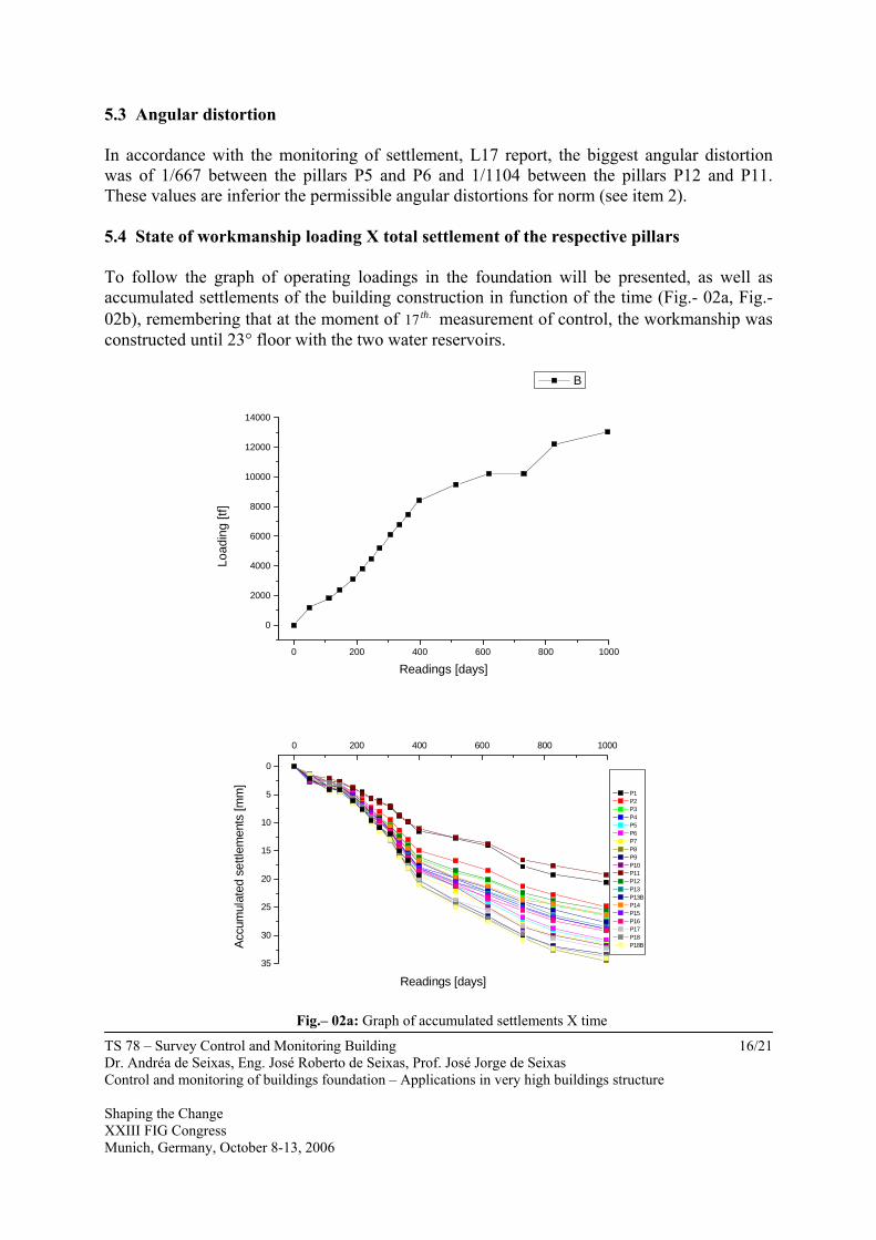
5.3 Angular distortion In accordance with the monitoring of settlement, L17 report, the biggest angular distortion was of 1/667 between the pillars P5 and P6 and 1/1104 between the pillars P12 and P11. These values are inferior the permissible angular distortions for norm (see item 2). 5.4 State of workmanship loading X total settlement of the respective pillars To follow the graph of operating loadings in the foundation will be presented, as well as accumulated settlements of the building construction in function of the time (Fig.- 02a, Fig.- 02b), remembering that at the moment of .17 th measurement of control, the workmanship was constructed until 23° floor with the two water reservoirs.
0 200 400 600 800 1000
0
2000
4000
6000
8000
10000
12000
14000
B
Load
ing
[tf]
Readings [days]
35
30
25
20
15
10
5
0
0 200 400 600 800 1000
P1 P2 P3 P4 P5 P6 P7 P8 P9 P10 P11 P12 P13 P13B P14 P15 P16 P17 P18 P18BAc
cum
ulat
ed s
ettle
men
ts [m
m]
Readings [days]
Fig.– 02a: Graph of accumulated settlements X time

TS 78 – Survey Control and Monitoring Building Dr. Andréa de Seixas, Eng. José Roberto de Seixas, Prof. José Jorge de Seixas Control and monitoring of buildings foundation – Applications in very high buildings structure Shaping the Change XXIII FIG Congress Munich, Germany, October 8-13, 2006
17/21
0 200 400 600 800 1000
0
2000
4000
6000
8000
10000
12000
14000
B
Load
ing
[tf]
Readings [days]
35
30
25
20
15
10
5
0
0 200 400 600 800 1000
P19 P20 P21 P21B P22 P23 P24 P25 P26 P26B
Accu
mul
ated
set
tlem
ents
[mm
]
Readings [days]
Fig.– 02b: Graph of accumulated settlements X time
5.5 Curve of isosettlements The Figure - 03(a) shows to the positioning of the pillars with respect the construction and the respective curves of isosettlements with corresponding equidistance of 1mm to total settlements in the tenth seventh measurement of control and monitoring of settlements:

TS 78 – Survey Control and Monitoring Building Dr. Andréa de Seixas, Eng. José Roberto de Seixas, Prof. José Jorge de Seixas Control and monitoring of buildings foundation – Applications in very high buildings structure Shaping the Change XXIII FIG Congress Munich, Germany, October 8-13, 2006
18/21
0 5000 100000
5000
10000
15000
20000
25000
30000
35000
40000
45000
0 5000 100000
5000
10000
15000
20000
25000
30000
35000
40000
45000
Figure - 03(a): position of the bolts and total curves of isosettlement of the 1mm in 1mm (L17)
TS 78 – Survey Control and Monitoring Building Dr. Andréa de Seixas, Eng. José Roberto de Seixas, Prof. José Jorge de Seixas Control and monitoring of buildings foundation – Applications in very high buildings structure Shaping the Change XXIII FIG Congress Munich, Germany, October 8-13, 2006
19/21
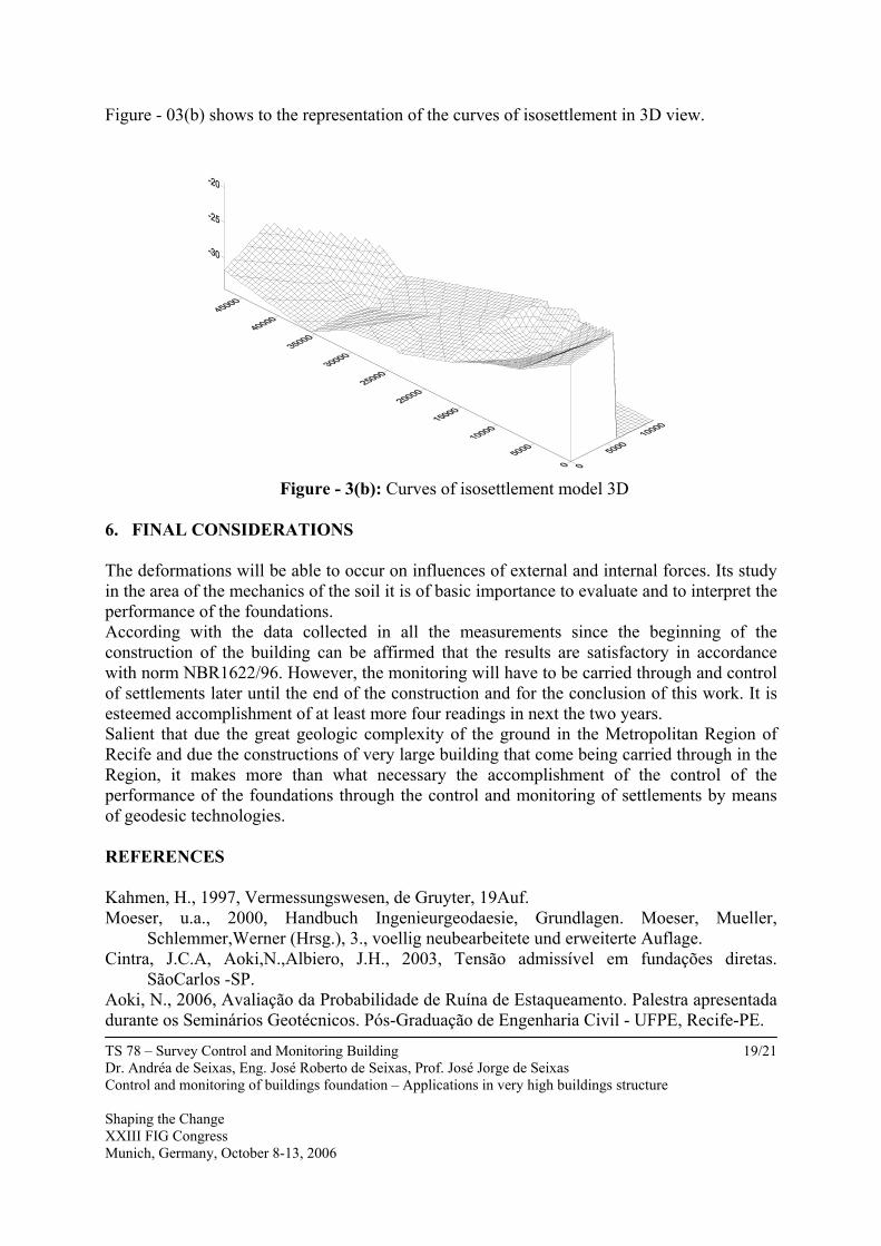
Figure - 03(b) shows to the representation of the curves of isosettlement in 3D view.
Figure - 3(b): Curves of isosettlement model 3D
6. FINAL CONSIDERATIONS The deformations will be able to occur on influences of external and internal forces. Its study in the area of the mechanics of the soil it is of basic importance to evaluate and to interpret the performance of the foundations. According with the data collected in all the measurements since the beginning of the construction of the building can be affirmed that the results are satisfactory in accordance with norm NBR1622/96. However, the monitoring will have to be carried through and control of settlements later until the end of the construction and for the conclusion of this work. It is esteemed accomplishment of at least more four readings in next the two years. Salient that due the great geologic complexity of the ground in the Metropolitan Region of Recife and due the constructions of very large building that come being carried through in the Region, it makes more than what necessary the accomplishment of the control of the performance of the foundations through the control and monitoring of settlements by means of geodesic technologies. REFERENCES Kahmen, H., 1997, Vermessungswesen, de Gruyter, 19Auf. Moeser, u.a., 2000, Handbuch Ingenieurgeodaesie, Grundlagen. Moeser, Mueller,
Schlemmer,Werner (Hrsg.), 3., voellig neubearbeitete und erweiterte Auflage. Cintra, J.C.A, Aoki,N.,Albiero, J.H., 2003, Tensão admissível em fundações diretas.
SãoCarlos -SP. Aoki, N., 2006, Avaliação da Probabilidade de Ruína de Estaqueamento. Palestra apresentada durante os Seminários Geotécnicos. Pós-Graduação de Engenharia Civil - UFPE, Recife-PE.

TS 78 – Survey Control and Monitoring Building Dr. Andréa de Seixas, Eng. José Roberto de Seixas, Prof. José Jorge de Seixas Control and monitoring of buildings foundation – Applications in very high buildings structure Shaping the Change XXIII FIG Congress Munich, Germany, October 8-13, 2006
20/21
Associação Brasileira de Normas Técnicas. NBR 6122/96: Projeto e execução de fundações.Rio de Janeiro, 1996. Associação Brasileira de Normas Técnicas. NBR 13133: Execução de levantamento topográfico. Rio de janeiro, 1994. Silva, T.F, De Seixas, A., Romão, V.M.C., 2004, Conceituação de campo de pontos na medição de deformação de objetos. Anais do I Simpósio de Ciências Geodésicas e Tecnologias da Geoinformação, Recife-PE. De Seixas, 2001, Objektrekonstruktion mittels Gitterlinien-Verfahren. Áustria. 128f. Tese de Doutorado. Instituto de Geofísica e Geodésia Aplicada. Departamento de Geodésia Aplicada à Engenharia. Universidade Técnica de Viena. De Seixas, A. et. al., 2005,Geodésia Aplicada à medição e ao monitoramento de áreas de risco em sítios industrializados. IV Colóquio Brasileiro de Ciências Geodésicas - UFPR. Curitiba – PR. Frota, R.G. O., Carvalho, C. S., Niyama, S, 1998, Fundações, Teoria e prática. Editores:
Waldemar Hachich, Frederico F. Falconi, José Luiz Saes. ABMS/ABEF, Segunda Edição.
Caputo, H. P., 1969, Mecânica dos solos e suas aplicações, Volume 2, Segunda edição. ACKNOWLEDGEMENT The authors are grateful to the Cientec Engenharia e Consultoria Ltda. For use instruments and permission to publish these observations in the paper. BIOGRAPHICAL NOTES Academic experience: Engª. Cartógrafa Dr.tech. Technical University of Vienna Current position: Vice-Charmain of Master Course – Ciências Geodésicas e Tecnologias da Geoinformação, UFPE Practical experience: Geodesic Engineering Activities International experience: projects in the Department of Geodesic Engineering at the Technical University of Vienna in 1995 – 2001, Vienna – Austria. Activities in home: Professor of Surveying for Graduation and Pos-Graduation Courses of the Federal University of Pernambuco – UFPE. Beginning at 2004.

TS 78 – Survey Control and Monitoring Building Dr. Andréa de Seixas, Eng. José Roberto de Seixas, Prof. José Jorge de Seixas Control and monitoring of buildings foundation – Applications in very high buildings structure Shaping the Change XXIII FIG Congress Munich, Germany, October 8-13, 2006
21/21
CONTACTS Andréa de Seixas Federal University of Pernambuco – UFPE Departamento de Engenharia Cartográfica Av. Acadêmico Hélio Ramos, s/n – Cidade Universidade 50740-530 – Recife/PE – Brasil Tel. + 55-81 - 21268235 and +55-81 – 21268149 Email: [email protected] ; [email protected] Web site: www.ufpe.br/decart