Contrail and Cirrus Cloud Avoidance TechnologyContrail and ...
176
C RANFIELD U NIVERSITY F RANK GN OPPEL C ONTRAIL AND C IRRUS C LOUD A VOIDANCE T ECHNOLOGY S CHOOL OF M ECHANICAL E NGINEERING P H DT HESIS
Transcript of Contrail and Cirrus Cloud Avoidance TechnologyContrail and ...

CRANFIELD UNIVERSITY
FRANK G NOPPEL
CONTRAIL AND CIRRUS CLOUDAVOIDANCE TECHNOLOGY
SCHOOL OF MECHANICAL ENGINEERING
PHD THESIS

CRANFIELD UNIVERSITY
SCHOOL OF MECHANICAL ENGINEERING
PHD THESIS
ACADEMIC YEAR 2006 - 2007
F G NOPPEL
CONTRAIL AND CIRRUS CLOUD
AVOIDANCE TECHNOLOGY
SUPERVISOR: RITI SINGH
OCTOBER 2007
THIS THESIS IS SUBMITTED IN PARTIAL FULFILMENT OF THE REQUIREMENTS
FOR THE DEGREE OFDOCTOR OFPHILOSOPHY
c©CRANFIELD UNIVERSITY 2007. ALL RIGHTS RESERVED. NO PART OF THIS
PUBLICATION MAY BE REPRODUCED WITHOUT THE WRITTEN PERMISSION OF
THE COPYRIGHT OWNER.

Abstract
Civil aviation, providing transport to connect people, cultures and economies, is
situated at the heart of globalisation. Since its earliest days, it has grown along
with every other part of the industrialised society and experienced growth rates ex-
ceeding that of global GDP. Projections suggest that futureair traffic emissions will
play an increasingly important role in the contribution to global warming, which is
regarded to be a serious threat to earth’s socio-ecologicalsystems.
Air traffic contributes to the overall anthropogenic radiative forcing, a metric de-
noting perturbations in the earth’s radiation budget, by the emission of greenhouse
gases and aerosols, and also by the generation of high ice clouds, commonly known
as contrails. Recent studies suggest that the radiative forcing resulting from con-
trails is potentially higher than that of all other air-traffic pollutants combined.
In light of this, contrail avoidance is attracting increasing interest from the aeronau-
tical community. An important contribution to the understanding of the problem in
a wider context is made in this thesis, alongside proposals for short, mid and long
term strategies for contrail avoidance. These are in particular the optimisation of
the aircraft for contrail avoidance, the application of remotely induced heat to sup-
press contrail formation, and a novel engine concept that exhibits the potential for
a reduction of all emissions simultaneously. Aircraft optimisation deals with the
adaptation of existing technology for more environmentally compatible air trans-
port, whereas the latter two approaches are breakthrough technologies of a more
disruptive character covered by several patents resultingfrom this research.
Short and mid term strategies are accompanied by an increasein carbon dioxide
emissions. A study examining the long-term impact of aviation carbon dioxide
emissions relative to that of contrails suggests that in order to achieve more sus-
tainable air transport, the avoidance of contrails is inevitable. However, as the
short-term impact of contrails is less severe, postponing contrail avoidance until
the associated increase in carbon dioxide emissions is lesssignificant could be a
better way to deal with the problem.
i

Acknowledgements
A very special thanks goes to my supervisor Riti Singh. His guidance through my
PhD was always a strong source of motivation and very valuable in all respects.
The financial support of my sponsor company, Rolls-Royce, and the advice of its
various employees is gratefully acknowledged.
Many thanks goes to Rachel Smith, who always provided the right solutions to so
many problems.
The support from Karl Geiselhart and Arnie McCullers from NASA Langley Re-
search Center on how to use NASA’s flight optimisation systemFLOPS is grate-
fully acknowledged.
The support of the BADC and MetOffice providing meteorological data was vital
for the completion of this project.
I would like to thank all people from the Department of Power and Propulsion
for their enduring support and the good time I had during my time at Cranfield
University. The individual contributions to this work by Francois Faupin, Cyril
Zinthaler, Dario Lucisano were very valuable.
Thank you to all friends and my family, who supported me in my activities and
with whom I shared good and hard times. Thanks also to Greg Ameyugo, who was
able to cope with me as office mate for three years.
ii

Contents
Table of contents . . . . . . . . . . . . . . . . . . . . . . . . . . . . . ii
List of figures . . . . . . . . . . . . . . . . . . . . . . . . . . . . . . . ix
List of tables . . . . . . . . . . . . . . . . . . . . . . . . . . . . . . . . xiii
Nomenclature . . . . . . . . . . . . . . . . . . . . . . . . . . . . . . . xiv
1 Introduction 2
1.1 Global warming . . . . . . . . . . . . . . . . . . . . . . . . . . . 2
1.1.1 The fundamentals of global warming . . . . . . . . . . . 5
1.1.2 Quantification of climate impacts . . . . . . . . . . . . . 6
Radiative forcing . . . . . . . . . . . . . . . . . . . . . . 7
Global warming potential . . . . . . . . . . . . . . . . . 8
Global temperature potential . . . . . . . . . . . . . . . . 9
iii

Other metrics . . . . . . . . . . . . . . . . . . . . . . . . 9
1.1.3 Trends . . . . . . . . . . . . . . . . . . . . . . . . . . . . 10
1.1.4 Mitigation . . . . . . . . . . . . . . . . . . . . . . . . . . 13
1.2 Aviation and the global atmosphere . . . . . . . . . . . . . . . . 14
1.2.1 Carbon dioxide . . . . . . . . . . . . . . . . . . . . . . . 15
1.2.2 Water vapour . . . . . . . . . . . . . . . . . . . . . . . . 17
1.2.3 Soot and Aerosols . . . . . . . . . . . . . . . . . . . . . 17
1.2.4 NOx . . . . . . . . . . . . . . . . . . . . . . . . . . . . . 18
1.2.5 Contrails . . . . . . . . . . . . . . . . . . . . . . . . . . 18
1.2.6 Contrail cirrus . . . . . . . . . . . . . . . . . . . . . . . 21
1.2.7 Secondary cirrus . . . . . . . . . . . . . . . . . . . . . . 22
1.2.8 Summary . . . . . . . . . . . . . . . . . . . . . . . . . . 22
1.3 The role of aviation in a global context . . . . . . . . . . . . . . .22
1.4 Thesis objective . . . . . . . . . . . . . . . . . . . . . . . . . . . 26
1.5 Thesis structure . . . . . . . . . . . . . . . . . . . . . . . . . . . 27
2 Literature survey 28
2.1 Contrails . . . . . . . . . . . . . . . . . . . . . . . . . . . . . . . 28
iv
2.1.1 Thermodynamics . . . . . . . . . . . . . . . . . . . . . . 29
2.1.2 Plume chemistry . . . . . . . . . . . . . . . . . . . . . . 35
Non-volatile precursors . . . . . . . . . . . . . . . . . . . 37
Volatile precursors . . . . . . . . . . . . . . . . . . . . . 38
Particle growth . . . . . . . . . . . . . . . . . . . . . . . 43
Particle size . . . . . . . . . . . . . . . . . . . . . . . . . 43
Summary . . . . . . . . . . . . . . . . . . . . . . . . . . 44
2.1.3 Radiative forcing of contrails . . . . . . . . . . . . . . . . 46
2.1.4 Wake dynamics . . . . . . . . . . . . . . . . . . . . . . . 47
2.1.5 Ice-supersaturated regions . . . . . . . . . . . . . . . . . 50
2.2 Contrail cirrus clouds . . . . . . . . . . . . . . . . . . . . . . . . 51
2.3 Secondary cirrus clouds . . . . . . . . . . . . . . . . . . . . . . . 53
2.4 Natural cirrus modification . . . . . . . . . . . . . . . . . . . . . 54
2.5 Aerodynamic contrails . . . . . . . . . . . . . . . . . . . . . . . 54
3 Contrail avoidance strategies 56
3.1 Adjustment of air traffic . . . . . . . . . . . . . . . . . . . . . . . 58
3.1.1 Temporal adjustment of air traffic . . . . . . . . . . . . . 62
v

3.1.2 Spatial adjustment of air traffic . . . . . . . . . . . . . . . 63
(a) change cruise altitude on a global scale . . . . . . . . 66
(b) restrict cruise altitudes temporarily . . . . . . . . . . . 69
(c) change aircraft cruise altitude during flight . . . . . . . 69
3.2 Engine technology . . . . . . . . . . . . . . . . . . . . . . . . . 73
3.2.1 Distributed propulsion and remotely driven fans . . . .. . 78
3.2.2 A clean exhaust engine concept . . . . . . . . . . . . . . 79
Cycle optimisation . . . . . . . . . . . . . . . . . . . . . 86
3.3 Aircraft technology . . . . . . . . . . . . . . . . . . . . . . . . . 91
3.3.1 Aircraft optimisation . . . . . . . . . . . . . . . . . . . . 92
3.3.2 Airframe and engine integration . . . . . . . . . . . . . . 105
3.4 Fuels . . . . . . . . . . . . . . . . . . . . . . . . . . . . . . . . . 107
3.4.1 Fuel sulphur content . . . . . . . . . . . . . . . . . . . . 108
3.4.2 Fuel additives . . . . . . . . . . . . . . . . . . . . . . . . 108
3.4.3 Hydrogen . . . . . . . . . . . . . . . . . . . . . . . . . . 109
3.5 Contrail avoidance devices . . . . . . . . . . . . . . . . . . . . . 111
3.5.1 Remotely induced evaporation . . . . . . . . . . . . . . . 113
vi

3.5.2 Remotely induced heat to suppress condensation . . . . .116
3.5.3 Sonication . . . . . . . . . . . . . . . . . . . . . . . . . 117
3.5.4 Chemical devices . . . . . . . . . . . . . . . . . . . . . . 117
4 Contrails vs. carbon dioxide 120
5 Conclusions 131
5.1 Recommendations . . . . . . . . . . . . . . . . . . . . . . . . . . 137
5.1.1 Assessing the environmental impact of contrails . . . .. . 137
5.1.2 Recommendations on avoidance technologies . . . . . . . 138
References 138
A Appendix 154
A.1 Derivation of the mixing line slope . . . . . . . . . . . . . . . . . 154
A.2 Tools . . . . . . . . . . . . . . . . . . . . . . . . . . . . . . . . . 155
A.2.1 FLOPS . . . . . . . . . . . . . . . . . . . . . . . . . . . 156
A.2.2 ESDU flight performance program . . . . . . . . . . . . . 156
A.2.3 TURBOMATCH . . . . . . . . . . . . . . . . . . . . . . 157
A.3 Operational weather analysis data . . . . . . . . . . . . . . . . . 157
vii

A.4 Baseline aircraft . . . . . . . . . . . . . . . . . . . . . . . . . . . 157
Publications . . . . . . . . . . . . . . . . . . . . . . . . . . . . . . . . 158
viii

List of Figures
1.1 Climate change: source, impact and response. . . . . . . . . .. . 4
1.2 Carbon dioxide concentration over time. . . . . . . . . . . . . .. 11
1.3 Global mean radiative forcing. . . . . . . . . . . . . . . . . . . . 12
1.4 Global temperature over time. . . . . . . . . . . . . . . . . . . . 13
1.5 Influence of aircraft emissions on the atmosphere. . . . . .. . . . 15
1.6 World carbon dioxide emissions by sector. . . . . . . . . . . . .. 16
1.7 Photo of contrails of different ages. . . . . . . . . . . . . . . . .. 19
1.8 Departure of average diurnal temperature ranges. . . . . .. . . . 20
1.9 Photo of contrail cirrus cloud. . . . . . . . . . . . . . . . . . . . 21
1.10 Radiative forcing from aviation. . . . . . . . . . . . . . . . . . .23
1.11 Aircraft energy intensity of aircraft. . . . . . . . . . . . . .. . . 24
1.12 Aviation growth in terms of seat kilometers offered. . .. . . . . . 25
ix

2.1 Phase diagram of water. . . . . . . . . . . . . . . . . . . . . . . . 30
2.2 Geometrical analysis of contrail formation. . . . . . . . . .. . . 33
2.3 Contrail formation observations. . . . . . . . . . . . . . . . . . .35
2.4 Photo of threshold contrail. . . . . . . . . . . . . . . . . . . . . . 36
2.5 Photo of a persistent contrail. . . . . . . . . . . . . . . . . . . . . 36
2.6 Soot activation and heterogeneous freezing model. . . . .. . . . 39
2.7 Model for the formation of sulfuric acid. . . . . . . . . . . . . .. 41
2.8 Exhaust particle size distribution. . . . . . . . . . . . . . . . .. . 44
2.9 Schematic of plume aerosol dynamics. . . . . . . . . . . . . . . . 45
2.10 Relative ice-supersaturation frequency. . . . . . . . . . .. . . . . 51
3.1 Interdependencies in the contrail formation process. .. . . . . . . 59
3.2 Probability for contrail formation. . . . . . . . . . . . . . . . .. 60
3.3 Area probability for contrail formation. . . . . . . . . . . . .. . 61
3.4 Relative change in inverse specific air range. . . . . . . . . .. . . 66
3.5 Absolute change in overall engine efficiency. . . . . . . . . .. . 67
3.6 Change in contrail cover and radiative forcing. . . . . . . .. . . . 68
3.7 Annual variation in contrail formation. . . . . . . . . . . . . .. . 72
x

3.8 Minimum engine efficiency required for contrail formation. . . . . 74
3.9 Areas where the formation of contrails is facilitated. .. . . . . . . 77
3.10 Contrail formation for different efficiencies. . . . . . .. . . . . . 78
3.11 Remotely driven fans. . . . . . . . . . . . . . . . . . . . . . . . . 80
3.12 Novel engine concept vs. intercooled recuperated engine cycle. . . 82
3.13 Engine stations on a phase diagram of water. . . . . . . . . . .. . 84
3.14 NOx reduction through water injection . . . . . . . . . . . . . . . 86
3.15 SFC vs. specific thrust. . . . . . . . . . . . . . . . . . . . . . . . 88
3.16 η vs. TET. . . . . . . . . . . . . . . . . . . . . . . . . . . . . . . 89
3.17 OPR vs. TET. . . . . . . . . . . . . . . . . . . . . . . . . . . . . 89
3.18 BPR vs. TET. . . . . . . . . . . . . . . . . . . . . . . . . . . . . 90
3.19 FPR vs. TET. . . . . . . . . . . . . . . . . . . . . . . . . . . . . 90
3.20 Aircraft design process considering contrail formation. . . . . . . 94
3.21 Mission definition and constraints. . . . . . . . . . . . . . . . .. 95
3.22 Schematic of calculation of air-traffic density. . . . . .. . . . . . 96
3.23 Air traffic density. . . . . . . . . . . . . . . . . . . . . . . . . . . 97
3.24 Critical mixing line slope. . . . . . . . . . . . . . . . . . . . . . . 98
xi

3.25 Journey length distribution for aircraft with 200-250seats. . . . . 100
3.26 Fuel burn penalty relative to baseline configuration. .. . . . . . . 101
3.27 Relative change in design variables. . . . . . . . . . . . . . . .. 102
3.28 Change in contrail formation relative to baseline configuration. . . 103
3.29 Change in contrail formation relative to baseline configuration. . . 104
3.30 Fuel savings of unducted fan. . . . . . . . . . . . . . . . . . . . . 106
3.31 Minimum engine efficiency required for contrail formation. . . . . 110
3.32 Remotely induced contrail avoidance. . . . . . . . . . . . . . .. 112
3.33 Remotely induced ice particle sublimation. . . . . . . . . .. . . . 114
3.34 Temperature difference to saturated conditions. . . . .. . . . . . 115
4.1 Contrail avoidance with respect to current technology.. . . . . . . 121
4.2 Global CO2 concentration for the IPCC scenarios A1B and B1. . . 123
4.3 Global temperature change. . . . . . . . . . . . . . . . . . . . . . 129
4.4 Global temperature change from aviation only. . . . . . . . .. . . 130
5.1 Fuel burn penalty associated with contrail avoidance. .. . . . . . 134
xii

List of Tables
3.1 Global average area probability for contrail formation. . . . . . . 61
3.2 Parameters for minimum engine efficiency calculations.. . . . . . 73
3.3 Energy specific emission index for different fuels. . . . .. . . . . 107
4.1 Aircraft technology parameters. . . . . . . . . . . . . . . . . . . 125
A.1 Aircraft parameters. . . . . . . . . . . . . . . . . . . . . . . . . . 157
xiii

Nomenclature
BF Block fuel (fuel/passenger).
λ Climate feedback parameter [W/(m2K)].
cp Specific heat capacity [J/(kgK)].
∆ Finite difference.
S Distance.
DTI Department of Trade and Industry (UK).
EI Emission index [kgemission/kgf uelburned].
η Efficiency.
S Flight path length.
GDP Gross domestic product.
GTP Global temperature potential.
GTPP Global temperature potential.
GTPS Global temperature potential.
GWP Global warming potential.
xiv

h enthalpy [J/(kg)]
HPC High pressure compressor.
HPT High pressure turbine.
ω Humidity ratio (specific humidity) [kgwater/kgair ].
IEA International Energy Agency.
IPCC Intergovernmental panel on climate change.
ISAR Inverse specific air range [kgf uel/(kgpayloadkm)].
L/D Lift to drag ratio.
LPC Low pressure compressor.
LPT Low pressure turbine.
m Mass [kg].
M Molar mass ratioM/M.
qnet Fuel net calorific value [J/kg].
OPR Overall engine pressure ratio.
P Power [W].
R gas constant [J/(kgK)]
RF Radiative forcing [W/m2].
φ Relative humidityp/psaturation.
RS Ratio passenger weight to empty aircraft weight.
xv

cp Specific heat capacityJ/(kg K).
SKO Seat kilometres offered.
σ Slope of curve in a humidity chart [Pa/K].
T temperature [K, oC]
TAS True air speed [km/h, m/s, knots].
TET Turbine entry temperature [K].

Chapter 1
Introduction
1.1 Global warming
The earth’s atmosphere is a protective layer of air enablinglife in its form as we
know it today. It shields cosmic radiation and holds elements crucial for the emer-
gence of biologic life. Weather phenomena, which is the large scale movement of
air and evaporation and precipitation of water, occur in theatmosphere. The scale
and strength of weather events is primarily dependent on theamount of energy in
the atmosphere. This energy is provided by the sun in the formof cosmic radiation,
heating the planet’s atmosphere. The heating occurs due to absorption and emission
of thermal radiation by some of the air molecules. The dominant absorbers of solar
radiation are CO2 and water vapour. Without this warming effect, the earth’s atmo-
sphere would be much cooler, and unhabitable for the majority of species currently
occupying the planet.
This warming effect was firstly recognised in 1827 by Jean-Baptiste Fourier, who
2

observed it in greenhouses and drew parallels to the atmosphere. In a greenhouse,
solar radiation is passing the glass almost unimpeded and isthen absorbed by plants
and the soil, which re-emit it in form of thermal infrared radiation. However, the
infrared radiation is absorbed by the glass and scattered back into the greenhouse,
which has the effect of keeping the temperature higher than without the surrounding
glass. Based on this observation, the atmospheric warming was called greenhouse
effect, and the radiation absorbing gases in the atmosphereare called greenhouse
gases. Without greenhouse gases, the earth’s atmosphere would be 21oC or so
lower. The blanketing due to naturally present greenhouse gases in the atmosphere,
and the associated temperature difference, is known as the natural greenhouse ef-
fect.
An increasing greenhouse gas concentration would have an effect on the average
global temperature because more thermal radiation would beabsorbed. John Tyn-
dall measured the absorption of infrared radiation by CO2 and water vapour around
1860, and Arrhenius [1896] first speculated that changes in the levels of CO2 in the
atmosphere could substantially alter the surface temperature through the green-
house effect. In 1940, Guy Stewart Callendar linked rising carbon dioxide con-
centrations in the atmosphere to global temperature. It is believed that he was the
person who for the first time forecasted a global temperaturerise due to increasing
CO2 concentrations as a result of burning fossil fuels. Revelleand Suess [1957]
pointed out that the anthropogenic increase in CO2 concentration would create an
enhanced greenhouse effect, potentially causing significantly elevated global tem-
peratures in the long term. The change in temperature would in return cause a
change in variations of weather, known as climate change.
According to numerous studies, an increase in temperature will provoke a more
hydrological cycle with more water vapour in the atmosphereand more severe
weather events. While most areas expected to experience negatively associated
3

Food and Water ResourcesEcosystem and BiodiversityHuman SettlementsHuman Health
Temperature RiseSea Level RisePrecipitation ChangeDroughts and Floods
Economic GrowthTechnologyPopulationGovernance
Greenhouse GasesAerosols
Climate Change Impacts on Human
Socio−EconomicEmissions and
and Natural Systems
Concentrations Development PathsMitigation
Adaptation
Adaptation
Contrails
Figure 1.1: Climate change: source, impact and response [adopted from Houghton,2004].
consequences such as more frequent and severe droughts or sea level rise, other
areas might experience beneficial effects. But it is the abruptness of the change
that is of greatest concern. If it occurred slowly enough, socio-ecological systems
would be able to gradually adapt to it. A sudden change, as observed during the last
decades, will have consequences that are hard to foresee. But most likely, human
and natural ecosystems will find it difficult to adapt.
An integrated view of climate change is given in 1.1. Human activities in its vari-
ous forms, such as emissions or deforrestration, impact theglobal climate. Climate
change, in return, has an indirect impact on human or naturalsystems. Communi-
ties and natural systems can respond to changes in two ways: adaptation is aimed
at reducing the effects due to climate change, and mitigation is aimed at reducing
the cause of climate change.
The continually increasing demand in fossil fuels and projections regarding future
emissions have led to the topic of global warming coming on top of political agen-
4

das. Governments are increasingly accepting the underlying science and thanks
to the moral and economic pressure, cleaner energy sources are now anticipated
to be put into place [The Economist print edition, 2007]. Policies and new regula-
tions will require companies and private individuals to adopt more environmentally
friendly technologies. Companies started realizing that although global warming
is a cost driver, it may also provide new opportunities. New markets, technologies
and businesses emerge, where revenues can be created. The change to alternative
technologies, evoked through the introduction of policies, can occur in a disrup-
tive manner. Sudden emergences of CO2 reducing measures will be beneficial to
companies that have positioned themselves well. It is believed that the firms which
spent money on more environmentally friendly technologiesare more likely to do
well out of CO2 emission constraints.
1.1.1 The fundamentals of global warming
Regarding earth as a closed system, solar incoming short-wave radiation is either
absorbed or reflected back into space. Absorbed radiation isconverted into heat
energy, keeping the planet at a habitable temperature. Following the Boltzman law,
a body of temperature above absolute zero Kelvin is radiating, whereas the intensity
of the radiation depends on the body’s temperature. Under equilibrium conditions,
terrestrial infrared radiation due to the earth’s temperature is offset by incoming
solar radiation, and the energy fluxes of the ingoing and outgoing radiation are
equal.
Pollutants, such as greenhouse gases, impose a perturbation on the equilibrium
state by absorbing additional heat energy. The amount of energy absorbed is de-
noted by radiative forcing (RF), which is the amount of radiation forced to remain
within system earth, i.e. the atmosphere, oceans and soil. As more and more heat
5
is absorbed, the earth’s temperature increases. The radiative forcing of a particu-
lar pollutant depends on its spatial distribution and its interaction with solar and
terrestrial radiation [Shine and de Forsters, 1999]. A temperature rise will occur
over time until the outgoing and the ingoing radiation are inequilibrium again.
The expected steady state equilibrium temperature change due to a certain pollu-
tant depends on the strength of its radiative forcing. A positive radiative forcing
will cause a temperature rise, whereas a negative radiativeforcing will cause a
temperature drop.
Furthermore, the temperature change is also determined by the climate feedback
parameterλ. It can be understood as a gain factor, accounting for three-dimensional
atmosphere-ocean feedback mechanisms such as cloud or sea ice formation. The
value of the climate feedback parameter varies from model tomodel. Despite vast
improvements in climate modelling techniques, its quantification remains little im-
proved and its uncertainty is often used by climate change sceptics to denounce
climate change predictions [Lindzen et al., 2001].
1.1.2 Quantification of climate impacts
The quantification of the impacts of pollutants is fundamental for the assessment
of global warming and its consequences. Metrics are used to identify and com-
pare contributions from polluters on a global scale down to individuals. They
support the development of pollutant abatement strategiesand support decision-
making processes. A metric can either represent the amount of pollutants released
in the atmosphere or the impact they have on the environment,whereas the impact
on the environment can be broken down into several levels. Regarding the impact
of emission as a chain [Shine et al., 2005], the levels are: emissions→ radiative
forcing → climate impact→ societal and ecosystem impact. Although the rele-
6

vance of the impacts increases further down the chain, thereis a corresponding
increase in uncertainty and complexity in computational techniques. Ultimately,
a metric reflecting the impact on the socio-economic development paths would be
most desirable. In the following, the most important metrics that are used today
will be introduced.
Radiative forcing
In a very simplified representation, the steady-state global mean surface temper-
ature change due to perturbations in the planetary’s radiation budget relative to a
baseline temperature is defined as
∆Ts = λRF (1.1)
where∆Ts is the temperature change,λ is the climatic feedback parameter and RF
is the radiative forcing. Radiative forcing is expressed interms of Watt per square
meter, denoting the energy flux per unit earth’s area forced to stay on earth. A
positive forcing tends to warm the system, while a negative forcing tends to cool
it. Efficacy is a term often associated with radiative forcing. It is defined as the
ratio of the climate sensitivity parameter for a given forcing agent relative to the
response produced by a standard CO2 forcing from the same initial climate state
[Hansen et al., 2005].
The radiative forcing of gaseous agents is dependent on their concentration, which
is determined by the accumulated emissions in the atmosphere. Pollutants with
long residence times, such as CO2 cause a radiative forcing up to several decades
after emission until they are absorbed by the natural environment. An immediate
abatement of all carbon dioxide emissions would only resultin a gradual decay of
7

the CO2 concentration and the associated radiative forcing. Radiative forcing is
therefore a metric reflecting the current impact of past emissions. Other emissions,
such as contrails, have much shorter residence times. They stay in the upper tro-
posphere only up to some hours. Immediate avoidance would befollowed almost
instantaneously with the radiative forcing diminishing tozero.
Global warming potential
Global warming potential (GWP) is a metric for the contribution of a certain pollu-
tant to global warming. It is a relative scale, comparing theenvironmental impact
of a pollutant to that of the same mass of a reference gas, which is commonly
CO2 and has a GWP of one by definition. The definition of GWP is the “ratio
of the time-integrated radiative forcing from the instantaneous release of 1kg of a
substance relative to that of 1 kg of a reference gas.” In thiscase, the term “instan-
taneous” refers to a pulse emission of a certain amount of thepollutant. Quoting
the GWP without specifying the length of the time period is meaningless. In the
Kyoto Protocol, the time period is fixed to 100 years, although shorter and longer
timescales are possible to calculate. Today, the time span of 100 years is commonly
used as time period for calculating the GWP.
Unfortunately, the global warming potential is regarded tobe not a suitable measure
for the influence of aviation emissions [Rogers and Shine, 2005]. It is a metric that
reflects the effect of one tonne of emitted pollutant gas, assuming the gas to be
homogeneously distributed in the atmosphere and to have a reasonably long life-
time. However, aviation pollutants such as NOx or contrails are more short lived,
and their occurrence is more confined to certain regions and altitudes. Additionally,
the environmental impact of some aviation pollutants is dependent on factors such
their geographical location of release, the time when or also altitude where they
8
were emitted.
Global temperature potential
Alternatives to the GWP for comparing the climate impact of emissions of green-
house gases have been proposed by Shine et al. [2005]. Two different greenhouse
gases, one strong with a short life-time and the other weak with a long live-time, can
have the same GWP. At a given time, however, the temperature response due to a
pulse emission might be different. Two metrics are proposedin Shine et al. [2005],
both called the Global Temperature Change Potential (GTP),covering pulsed emis-
sions (GTPP) and sustained emissions (GTPS). They represent the temperature
change at a given time due to a pulse emission of a gas, making interpretation
unambiguous as opposed to the GWP.
Both the GTPP and the GTPS are one step down in the chain on page6. They are
capable of modelling the influence of short-lived species, and are more applicable
for quantifying the influence of aviation emissions on the global climate.
Other metrics
At the end of the chain of pollutants and their environmentalimpacts on page 6
are the societal and ecosystem impact. An assessment of pollutants regarding the
societal and ecosystem impact would be most relevant, but due to their complexity,
they are difficult to calculate. Attempts are made to measurethe climate impact in
terms of abatement cost or welfare loss applying empirical approaches, and is be-
coming more and more common to quote fiscal numbers. The use offiscal numbers
is particularly attractive for policy makers and in industry because climate change
9

can be associated with a cost. As industry is profit driven, the association of climate
change with a cost gives incentives to reduce their environmental footprint.
1.1.3 Trends
Carbon dioxide is the dominant mode through which carbon is constantly trans-
ferred in the natural environment between a variety of carbon reservoirs. Burning
fossil fuels, which is one reservoir, means taking carbon from beneath the earth’s
surface, converting it to CO2 and emitting it into the atmosphere. The accumulation
of carbon dioxide in the atmosphere occurs due to the absenceof sufficient natu-
ral carbon dioxide sinks. The atmospheric concentration ofCO2 and that of other
pollutants are constantly recorded. Etheridge et al. [1996] derived the change in
carbon dioxide concentration over the past from Antarctic ice core measurements.
Results are shown in figure 1.2, showing an increasing trend of the atmospheric
carbon dioxide concentration since the beginning of the industrial revolution. Es-
pecially during the last few decades, the atmospheric carbon dioxide concentration
has increased sharply.
Human contributions to global warming are constantly assessed by the Intergovern-
mental Panel on Climate Change (IPCC), which has been established to improve
the understanding of climate change, its potential impactsand options for adapta-
tion and mitigation. Figure 1.3 is provided by the IPCC, summarizing the principal
human induced mechanisms that force climate change. Not only the emission of
greenhouse gases contributes to global warming, but also e.g. the alteration of sur-
face reflectance by land use. The only forcing in figure 1.3 that is of non-human
origin comprises the variations in the output of the sun. Some of the radiative forc-
ing agents, such as such as CO2, are homogeneously distributed over the globe.
Other perturbations, such as aerosols, have more distinct regional signatures be-
10

Figure 1.2: Global carbon dioxide concentration [adopted from Etheridge et al.,1996].
cause of their spatial distribution. Therefore, but also due to other reasons, the
cumulative of all displayed radiative forcings cannot be expected to yield the net
effect on the climate system.
As the atmospheric concentration or occurrence of a certainpollutant changes, so
does its radiative forcing. For pollutants with relativelyshort lifetimes, an instant
change in their emission rates, which could be measured in mass units or occur-
rences per unit of time, would then almost instantaneously provoke a change in
their radiative forcing. Species with long life times, suchas CO2, accumulate in
the atmosphere. Even if the emission of CO2 was avoided instantaneously, it would
take decades until all CO2 of human origin was absorbed and the radiative forcing
due to CO2 settled to preindustrial levels.
Today, climate models are used to learn about likely climatechange and beyond.
11

Figure 1.3: Global mean radiative forcing in 2000 relative to 1750 [adopted fromIPCC Working Group 1, 2001].
Because of the uncertainty associated with simplificationsin climate models and
emission forecasts, the results of climate models are referred to as scenario projec-
tions rather than predictions. Emission scenarios, such asdeveloped by the IPCC
in IPCC [2000], are forecasts of emissions making assumptions regarding human
behaviour and activities such as population, economic growth or energy efficiency.
Based on the considered emission scenarios, estimates regarding the future global
temperature can be made. Abatement strategies can be testedby implementing
them into the climate model. Figure 1.4 shows a variety of temperature projections
considering several scenarios. The calculated temperature change due to anthro-
pogenic activities relative to the year 2000 is in the range between 1.5 and 4K.
12

Figure 1.4: Global averaged and assessed ranges for surfacewarming [adoptedfrom IPCC, 2007].
1.1.4 Mitigation
Because earth is the principal enabler for human life as a matter of principle, it
becomes intuitively plausible to regard is as common property [Hoffe, 2004]. And
this property is shared over generations in equal measures.Justice teaches, and
it is anchored in the genes of the human species, to provide anequally habitable
environment for future generations. The principal driver in evolution has always
been the desire to protect offspring. Global warming puts the global population
at a risk, and it is our responsibility to react accordingly to changes in the global
climate and the threats that come with it.
New technologies, both technological and operational, arebeing developed to re-
duce the environmental footprint of the international economies. Incentives are put
into place where no natural desire for the implementation ofcleaner technologies
13

exist. This can usually be achieved through the introduction of policies, regula-
tions, taxation or emissions trading, taking place globally, nationally or regionally,
but also within more constrained borders such as companies or institutions. In the
long term, a competitive advantage may exist for companies with cleaner technolo-
gies, especially if the education of the end consumer causesa paradigm shift. The
complexity of the interactions of global warming with economic, political, social
and technological processes imposes uncertainty and the risk of irreversibility on
the decision making processes.
Climate change mitigation has a mutual influence on broader socio-economic trends
such as development, sustainability or equity, and policies may promote sustainable
development when they are consistent with broader societalobjectives if they yield
benefits outside their initially pursued area. An unequal distribution of resources
among communities and between generations, as well as the cost that comes with
mitigation, have to be taken into account during the analysis of climate change
mitigation options.
1.2 Aviation and the global atmosphere
Aircraft pollutants are radiatively or chemically active substances which can reflect
or absorb solar or terrestrial radiation or alter the chemical composition of the at-
mosphere. Karcher [1999] provides a comprehensive reviewon aircraft emissions
and their impacts. Figure 1.5, adopted from this publication, shows the regions
of the earth’s atmosphere that are impacted by aircraft emissions. The principal
air-traffic pollutants in a global context are CO2, water vapour, NOx, soot, aerosols
and contrails. The emission of NOx in combination with CO and unburned hydro
carbons leads to the tropospheric production of ozone, and stratospheric depletion
14

Figure 1.5: Influence of aircraft emissions on the atmosphere [adopted fromKarcher, 1999].
of ozone. Sulphur species, nitrogen species and water contribute to the formation
of liquid particles, which can affect the tropospheric chemistry. Particulates and
water vapour lead to the formation of contrails, which, because of their radiative
properties, contribute to global warming.
1.2.1 Carbon dioxide
Carbon dioxide emerges during the combustion of kerosene, and emissions rates
can be related linearly to fuel burn rates. The emission index of kerosene for carbon
dioxide is about 3.16, implying that for each mass unit of fuel burned, about 3.16
mass units of carbon dioxide are produced.
The present emissions of CO2 from air-traffic are about 8.4% of the overall CO2
emissions in the transport sector, or roughly 2% of all anthropogenic CO2 emis-
sions [Roger et al., 2002]. Figure 1.6 shows world greenhouse gas emissions by
sector for the year 2002. The figure was composed from data from the Interna-
tional Energy Agency (IEA). Relative to other industry sectors, air-traffic carbon
15

Public
electricity/heat
35%
Energy
5%
Industry
18%
Residential
8% Other Sectors
10%
Aviation
2%
Road Transport
18%
Other Transport
4%
Transport
Figure 1.6: World carbon dioxide emissions by sector with data from the IEA.
dioxide emissions appear to be relatively low. However, it is the forecasted growth
rates in air-traffic of 3-5% and the associated emissions that put pressure on the
aerospace industry [Airbus, 2003, Eyers et al., 2004]. As air-traffic is growing, its
emissions in terms of share and magnitude are considered to increase [Lee, 2004].
The radiative forcing of CO2 from a particular industry sector is attributed to the
accumulated amount of CO2 in the atmosphere. In general, this is true for every
pollutant. However, carbon dioxide has an atmospheric residence time of more
than 100 years. Hence, the accumulated carbon dioxide emissions of a particular
industry sector over the last 100 years are considered if theradiative forcing is cal-
culated. Aviation became commercially viable during the last 70 years, and the
radiative forcing from aviation CO2 as shown in figure 1.10 is that of the accumu-
lated CO2 emissions during that time period.
16

1.2.2 Water vapour
Water, in vapour phase a relatively strong greenhouse gas, is also a combustion
product. The emission index of water is about 1.28. Water emitted in the tropo-
sphere precipitates relatively shortly after emission, whereas stratospheric water
can have longer residence times and hence a more significant radiative forcing. It
has been calculated that air-traffic water vapour emissionsaccount for about 5% of
the observed increase in stratospheric water content [Danilin et al., 1998]. How-
ever, according to Schumann et al. [2001], the radiative forcing from stratospheric
water vapour is marginal.
Water also plays an important role in the formation of contrails.
1.2.3 Soot and Aerosols
Atmospheric aerosol concentrations from air-traffic are relatively small compared
to the contribution from surface sources. Even at the prevailing rate of air-traffic
growth, the aerosol mass concentrations from aviation in 2050 are projected to
remain small [Penner et al., 1999]. Soot emissions tend to warm the atmosphere,
whereas sulfates have an opposite effect. Compared to otheraircraft emissions,
the direct radiative forcing of soot and aerosols is relatively small. Aerosols also
play an important role in the formation of cirrus clouds thatwould not form in the
absence of aviation, resulting in enhanced cloud formationand the modification of
the radiative properties of natural cirrus clouds.
17
1.2.4 NOx
The formation of NOx, a generic term for the mono-nitrogen oxides NO and NO2,
occurs at high temperatures within the engine. Mainly atmospheric nitrogen oxi-
dises to NO, which is quickly converted to NOx both inside the engine and in the
aircraft plume. Another nitrogen source is fuel, where it occurs in traces. NOx
emissions impact the global atmosphere in two ways. They produce ozone in the
upper troposphere, which is an effective greenhouse gas. Ozone formation due to
NOx emissions in the upper troposphere is more effective than atthe earth’s surface.
Apart from increasing tropospheric ozone concentrations,aircraft NOx emissions
decrease the concentration of another greenhouse gas: methane. A reduction in
methane implies a cooling of the atmosphere.
Tropospheric ozone concentrations are affected by air-traffic mainly in the north-
ern hemisphere, whereas the influence on methane concentrations is less spatially
confined. On a global scale, the average radiative forcings due to ozone production
and methane reduction offset each other partially, implying a relatively low overall
radiative forcing due to aviation NOx.
1.2.5 Contrails
Contrails are thin line-shaped ice clouds that can emerge inthe wake of an aircraft
(see figure 1.7). They were first observed during high-altitude flights in the 1920’s,
and air forces developed interest in contrails because theyenhanced the visibility
of their planes. The formation of contrails underlies many effects, such as chem-
ical reactions in the aircraft plume, aircraft wake dynamics, ice microphysics, the
state of the atmosphere within the flight corridors, atmospheric dispersion rates and
engine technology. Depending on the atmospheric conditions, contrails can either
18

Figure 1.7: Photo of contrails of different ages.
evaporate shortly after formation, or persist for time periods of up to some hours.
In average, the backscattering of terrestrial radiation bythe contrail’s ice crystals
is more effective than the reflection of solar radiation, creating a net positive ra-
diative forcing. First concerns regarding air-traffic and their effect on the climate
were made by Appleman [1966]. Back then, the announced introduction of a large
fleet of supersonic transport aircraft, which has never happened, initiated first stud-
ies. Later, the topic was picked up again by Changnon [1980].However, it was
concluded that an increase in cloudiness could not be considered as proof of a jet-
induced cirrus influence.
The potential effects of contrails on the climate were then again discussed by
Schumann and Wendling [1990]. Sausen et al. [1998] presented first estimates re-
garding global contrail coverage, and the issue found its way into the IPCC special
report [Penner et al., 1999]. Since then, a large number of studies have been per-
formed to understand formation mechanisms of contrails andtheir impact on the
global climate.
During the tragic events of the 11 September 2001, the airspace over the USA
was shut down for commercial and personal air-traffic for a time period of about
36 hours, resulting in the absence of contrails over the USA.Although contrails
19
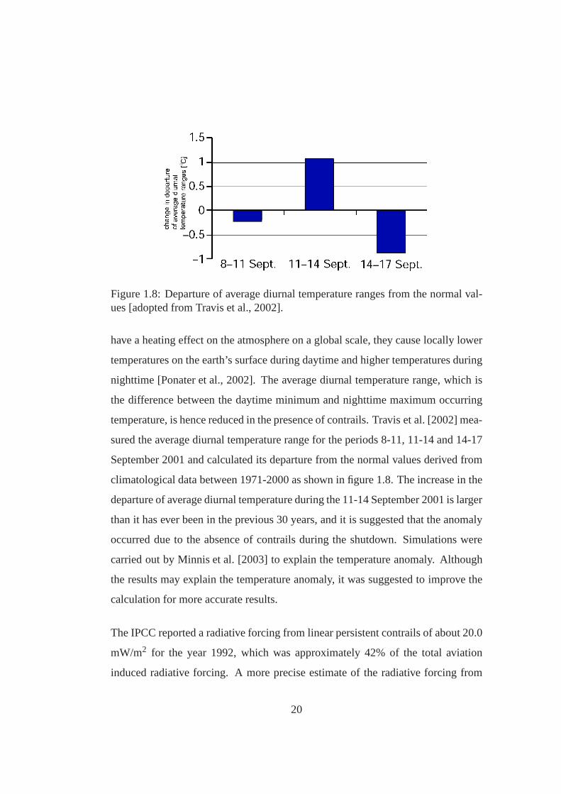
Figure 1.8: Departure of average diurnal temperature ranges from the normal val-ues [adopted from Travis et al., 2002].
have a heating effect on the atmosphere on a global scale, they cause locally lower
temperatures on the earth’s surface during daytime and higher temperatures during
nighttime [Ponater et al., 2002]. The average diurnal temperature range, which is
the difference between the daytime minimum and nighttime maximum occurring
temperature, is hence reduced in the presence of contrails.Travis et al. [2002] mea-
sured the average diurnal temperature range for the periods8-11, 11-14 and 14-17
September 2001 and calculated its departure from the normalvalues derived from
climatological data between 1971-2000 as shown in figure 1.8. The increase in the
departure of average diurnal temperature during the 11-14 September 2001 is larger
than it has ever been in the previous 30 years, and it is suggested that the anomaly
occurred due to the absence of contrails during the shutdown. Simulations were
carried out by Minnis et al. [2003] to explain the temperature anomaly. Although
the results may explain the temperature anomaly, it was suggested to improve the
calculation for more accurate results.
The IPCC reported a radiative forcing from linear persistent contrails of about 20.0
mW/m2 for the year 1992, which was approximately 42% of the total aviation
induced radiative forcing. A more precise estimate of the radiative forcing from
20

Figure 1.9: Photo of contrail cirrus cloud.
persistent linear contrails is given in Sausen et al. [2005]with 10.0 mW/m2, rep-
resenting approximately 20% of the total radiative forcingfrom air traffic. The
future development of contrail cover and the associated radiative forcing has been
investigated by Marquart et al. [2003]. Results suggest that annually and globally
averaged total contrail cover and the associated radiativeforcing approximately
quadruplicates during the next decades due to the increase in air-traffic.
1.2.6 Contrail cirrus
Persistent contrails form where the ambient humidity is nothigh enough to facili-
tate natural ice-cloud formation. Depending on the atmospheric condition, persis-
tent contrails can spread and form large area so called contrail cirrus clouds (see
figure 1.9). The radiative properties of contrail cirrus aresimilar to that of con-
trails, and the overall radiative forcing of contrail cirrus is believed to be several
times larger than that of contrails (see figure 1.10).
21

1.2.7 Secondary cirrus
Secondary cirrus can occur where soot and aerosol concentrations are elevated due
to air traffic [Jensen and Toon, 1997, Stordal et al., 2004, Zerefos et al., 2003b].
Additionally, an indirect impact from aircraft particulates is possible when ice crys-
tal size and number densities of natural cirrus clouds are modified [Kristensson et al.,
2000]. The increase in both cloudiness and cirrus cloud modification are believed
to cause a positive radiative forcing. Significant cirrus modification by black carbon
particles, very likely also yielding a positive radiative forcing, cannot be excluded
[Hendricks et al., 2005].
1.2.8 Summary
An estimate of all air-traffic emissions in terms of radiative forcing was first pub-
lished in Penner et al. [1999]. An update on the report by Sausen et al. [2005] pro-
vides more accurate estimates. In figure 1.10, the radiativeforcings from aviation
as they appear in both publications are shown.Although a precise estimate of the
radiative forcing from contrails, contrail cirrus, secondary cirrus and cirrus
modification is not possible at the current level of understanding, there is the
potential they cause a radiative forcing exceeding that of all other air-traffic
pollutants combined.
1.3 The role of aviation in a global context
Aviation is playing an important role in the modern society [Thomas and Raper,
2000]. Mobility and economic development is going hand in hand. Aviation is a
22

Figure 1.10: Radiative forcing from aviation for 1992 and 2000 [adopted fromSausen et al., 2005].
wealth creator, playing an integral role in business and commerce and supporting
the operation and competitiveness of global, regional and local economies by facil-
itating rapid transport of people and goods over large distances [ACI, 1998]. The
increase in services facilitates the development of societal, business and family net-
works, contributing to the mutual understanding of the different cultures [Nielsen,
2001]. Although it was believed that advances in information technology could
level off the demand in transport, the continued growth in the aerospace sector in
the recent years proves the opposite. The social and economic benefit from avia-
tion is significant, and will probably become more importantin future. In particular
emerging economies will benefit from an integrated network,linking them to the
major economic centres.
Since the advent of commercial air transport, the fuel efficiency of aircraft has been
improved steadily, yielding lower carbon dioxide emissions per revenue passenger
kilometer. In the past, however, the driving force for a better fuel economy was
not the environment. More fuel efficient aircraft give a competitive advantage over
23

less efficient aircraft as fuel drives direct operating cost, impacting profit margins
of airlines. Figure 1.11 shows the change of the average energy intensity in MJ
per revenue passenger kilometer of the commercial US aircraft fleet since the first
commercial jets. Advances in airframe and engine technology, as well as improve-
ments in air-traffic management, resulted in a decrease in average energy intensity
of about 60% between 1970 and 2000.
Figure 1.11: Historical trends of energy intensity of the commercial US aircraftfleet in terms of MJ per revenue-passenger kilometres [adopted from Lee et al.,2001].
Technological, physical and economical constraints, however, set limits to the na-
ture and scale of improvements, and technologies start maturing. Further im-
provements are becoming more and more difficult to achieve, and are accompa-
nied by higher capital cost. In terms of specific primary energy demand, a met-
ric considering most of the measurable losses that occur in transport in general,
24

Figure 1.12: Aviation growth in terms of seat kilometers offered (SKO) [adoptedfrom Roger et al., 2002; (with data from the DTI)].
Niedzballa and Schmitt [2001] have calculated that aircraft come second just after
container ships, outperforming rail and road transport. Air traffic has seen growth
rates exceeding that of global GDP despite the events on 11 September 2001. Fig-
ure 1.12 shows the increase in seat kilometres offered sine 1960, and a forecast
for the next decade. Comparing figures 1.12 and 1.11, it becomes apparent that he
improvement of aircraft technology is exceeded by the increase in passenger num-
bers, yielding in an overall increase in fuel consumption and hence carbon dioxide
emissions.
As global warming and its consequences cause a paradigm shift, governments and
interest groups are starting to demand action from stakeholders across all sec-
tors. Particularly the aviation sector has been challengedbecause of the forecasted
increase in emissions, and the aerospace industry, compared to just some years
ago, is now changing from “farther, further, higher” to “leaner, meaner, greener”
25

[McMasters and Cummings, 2003]. Although the most important contributer to
global warming in the aviation sector is regarded to be CO2, this might change
depending on the outcome of further studies on the environmental impact from
contrails and cirrus clouds.
1.4 Thesis objective
The current trend in passenger number growth rates and the associated effect on the
global atmosphere is believed to be unsustainable. Targetsregarding the reduction
of the environmental impact from air traffic, such as outlined in the ACARE goals
[Advisor Council for Aeronautics Research in Europe, 2002], are increasingly es-
tablished by policy makers and interest groups on national and international levels.
So far, the impact from contrails and cirrus clouds has not been addressed in agen-
das, despite the potential of having a radiative forcing several times higher than
that of all other air-traffic pollutants combined. Hence, itcan be expected that the
issue of contrail mitigation will be brought forward, and industry has an interest to
take measures that help to prevent a confrontation with the problem without being
unprepared.
In this thesis, the mitigation of the environmental impact from contrails and cir-
rus clouds is investigated. The principal aim is the identification and development
of strategies and technologies that have the potential to reduce contrail and cirrus
cloud forcings in future. First assessments of the strategies are conducted through-
out the thesis that can assist in the development of an agendafor further research
on this topic. Also, the long term impact of contrails and carbon dioxide emissions
is compared, which helps to understand underlying issues that come with contrail
avoidance.
26

1.5 Thesis structure
The remainder is divided into 5 chapters: the literature survey, contrail avoidance
strategies, contrails vs. CO2, discussion and conclusion. The literature survey
reviews the physical key processes involved in contrail formation and their envi-
ronmental impact. Based on the literature survey, contrailmitigation strategies and
technologies are derived and described in chapter 3. Chapter 4 investigates the rel-
ative environmental long-term impact of contrails compared to CO2. Conclusions
are given in chapter 5, along with recommendation on furtherwork. The appendix
contains information on data and tools used, mathematical expressions, and pro-
vides a list of publications.
27

Chapter 2
Literature survey
This chapter reviews the literature relevant for the development of contrail avoid-
ance strategies. Due to the multidisciplinary nature of thetopic, it was inevitable to
limit the content of this chapter to the fundamentals. References for a more com-
prehensive description are suggested throughout. For a better overview, already
existing contrail avoidance strategies are not described in the literature survey but
included in chapter 3.
2.1 Contrails
Generally, jet engines are thermodynamic machines utilising air as the working
medium, which provide thrust to enable sustained flight of aircraft at high alti-
tude and speed. Jet engines ingest air, which is then compressed, mixed with fuel,
burned and expanded in the turbine and the nozzle. The turbine is delivering shaft
power to the compressors, and some mechanical power is extracted to produce
28

electricity in a generator.
The gases leaving the nozzle are a mixture of the incoming airand combustion
products. For kerosene, the principal combustion productsare water and carbon
dioxide. For every mass unit of kerosene burned, approximately 1.25 mass units
of water are produced, in addition to the water already present in humid air. Be-
cause of the restrictions set by the laws of thermodynamics,only a fraction of the
chemical energy contained in the fuel can be converted into useful work. The un-
converted part of the energy is contained in the form of heat energy in the engine
exhaust. Hence, the jet efflux is hotter than the ambient air.
2.1.1 Thermodynamics
Depending on temperature and pressure, water can exist in three states: liquid,
solid or gaseous. This dependency can be measured and represented in form of a
phase diagram as shown in figure 2.1. If water in gaseous stateis rapidly cooled
or expanded, a phase change to either solid or liquid occurs.The phase transfor-
mation from gaseous to liquid involves the condensation of water in the form of
droplets once saturation pressure, denoting the pressure at a given temperature for
a particular phase change to happen under ideal conditions,is reached.
As droplets begin to form, the capillary attraction of the water molecules cause an
increase in pressure inside the droplet. Capillary attraction is a result of the co-
hesion force, the molecular force between molecules of a single substance. The
increase in pressure changes the state of the water back to gaseous, and the forma-
tion of droplets is prevented. This results in water being supersaturated, which is
the state where water exists in gaseous phase although the prevailing pressure and
temperature suggests liquid or solid phase. The amount of supersaturation can be
29

105
pressure [Pa]
temperature [K]273.15 373.15
condensation
ice
liquid
vapour
triple pointdeposition
sublimation
freezing
melting
boiling
Figure 2.1: Phase diagram of water.
expressed in terms of relative humidityPwater/Psaturation. It can be measured with
respect to liquid saturation pressure, or with respect to ice saturation pressure.
In the presence of small particles, so called condensation nuclei, condensation is
facilitated by the adsorption force between water and the condensation nuclei if
the adsorption force is larger than the cohesion force. In the atmosphere, where
water is contained in the air, supersaturation is required for droplet formation to
occur. The amount of supersaturation required to facilitate condensation typically
depends on the the size and material of condensation nuclei;it can be calculated
30

from
φdroplet = 1+σ
2 R Pw, s(2.1)
whereφdroplet is the relative humidity required to form a droplet of radiusR, σ is
the surface tension of the liquid1 andPw, s is the water saturation pressure. The
typical droplet size for a rain drop is 2000µm, for a cloud drop is 20µm and for a
cloud condensation nucleus is 0.2µm.
If atmospheric air is only slightly supersaturated with respect to water or ice, con-
densation or ice formation is not facilitated. This is firstly due to the increase in
pressure inside a droplet and hence the required level of supersaturation will be
above the ambient supersaturation level. Secondly, droplet formation would cause
a drop in the near-field supersaturation, resulting in a decrease of the ambient su-
persaturation level.
At the moment the moist and hot jet exhaust exits a jet engine,it mixes with ambient
air in the aircraft wake. As the mixing proceeds, the specifichumidity and temper-
ature in the plume diminishes. Depending on ambient and exhaust temperature and
water content, local humidity levels within the plume can elevate saturation levels
during the mixing process to an extent that condensation of water is facilitated. For
contrail forecast, it is desired to find the conditions at which supersaturation in the
plume occurs that facilitates condensation of water.
First attempts of contrail forecast have been undertaken byAppelman [1953], which
have later been reviewed by Schumann [1996]. The approach isbased on a geo-
metrical analysis of the mixing of the engine exhaust with ambient air on a phase
diagram of water. The temperature and water partial pressure of both the jet ex-
haust and the atmosphere can be found on a phase diagram of water. For the engine
exhaust, it is the stagnation temperature relative to the atmospheric frame of ref-
1σ = 0.073N/m for pure water in air
31

erence. In figure, 2.2, the state of the atmosphere is labelled with B. The state of
the exhaust gas, much hotter and containing more water than atmospheric air, is
indicated as A and lies outside the area of interest in figure 2.2.
The mixing of the engine exhaust with ambient air can be displayed as a straight
line, assuming the mixing taking place adiabatically and isobarically, and temper-
ature and humidity mixing at equal rates. The line connecting the points A and
B, representing the exhaust and the ambient air on the phase diagram, is generally
referred to as the mixing line. It represents the intermediate states that occur during
the mixing process. If the mixing line crosses the liquid saturation pressure line,
the condensation of water, and hence droplet formation, is facilitated. This case is
represented by the dashed line in figure 2.2. For exhaust gases that are hotter or
contain less water, the mixing line will not cross the saturation pressure line, and
the formation of contrails is not facilitated. This case is represented by the dotted
line in figure 2.2.
It has been found that the slope of the mixing lineσA,B can be calculated without the
knowledge of the plume stagnation temperature and water content. A dependency
on several other variables exist, which reads
σA,B =cp EIwater pa
qnet (1−η0) M(2.2)
wherecp is the specific heat capacity of air,EIwater is the water emission index,
pa is the ambient pressure,qnet is the fuel net calorific value,η0 is the overall
engine efficiency andM the molar mass ratio of water to air. See section A.1 in the
appendix for the derivation of equation 2.2.
For given ambient conditions, contrail formation is facilitated if the mixing line
slope exceeds the critical mixing line slope, known as the Appleman criterion.
32

−60 −55 −50 −45 −40 −35 −30 −25 −20 −15 −100
20
40
60
80
100
120
temperature [oC]
wat
er p
ress
ure
[Pa]
Water Saturation Pressure
Ice Saturation Pressure
Ambient Conditions
liquid
gaseous
ice
contrail
no contrail
criticalmixingline
A
A
B
Figure 2.2: Geometrical analysis of contrail formation.
Originating at the state of the atmosphere, it is the slope ofa tangent to the sat-
uration pressure curve originating in B, represented as blue solid line in figure 2.2.
The critical mixing line slope is dependent on ambient conditions and the quanti-
tative determination of the critical mixing line slope is aniterative process. The
temperature at which the critical mixing line slope is in contact with the saturation
pressure line can be obtained from solving
psat(Tcrit )− pambient
Tcrit −Tambient−
∂∂T
psat(Tcrit ) = 0 (2.3)
wherepsat(T) is the saturation pressure at a temperature T,pambient is the ambient
pressure,Tcrit is the temperature at which the critical mixing line is in contact with
33

the saturation pressure line andTambient is the ambient temperature. The saturation
pressure line as function of temperature can be found in literature. A common
approach to determine the saturation pressure is the Clausius-Clapeyron relation.
In this work, polynomials fits to the saturation pressures according to Flatau et al.
[1992] in the formpsat = a+b T +c T2+d T3+ ... are used throughout. Solving
equation 2.3 yieldsTcrit , from whichpcrit can be calculated and finally the mixing
line slope
σA,B =psat(Tcrit )− pambient
Tcrit −Tambient(2.4)
The geometric analysis for contrail forecast has been verified by numerous flight
tests carried out in Europe and the US. Schumann et al. [2000]conducted in-flight
experiments where ambient conditions and engine efficiencywere recorded to com-
pare theory against observation. Figure 2.3 summarizes contrail formation obser-
vations for a range of aircraft. It supports the assumption that contrails only form
if liquid supersaturation is reached in the plume.
Once water condensation has occurred in the plume, it is typically followed by
freezing as the temperature and humidity in the plume drops.If the atmosphere
is not sufficiently supersaturated, the ice crystals evaporate shortly after freezing,
and the contrail is very limited in its length. These kind of very short-lived con-
trails are called threshold contrails, which are considered not to contribute to global
warming. The photo in figure 2.4 shows a typical example.
If the atmosphere is sufficiently ice-supersaturated, the ice crystals will remain in
the air. The contrail then appears as elongated line shaped cloud following the
flight path of the aircraft. Figure 2.5 shows a photo of a persistent contrail. The life
time of the contrail is dependent on the ambient conditions,primarily the level of
ice-supersaturation.
34

Figure 2.3: Contrail formation observations [adopted fromKarcher et al., 1998].
2.1.2 Plume chemistry
Contrail particles are ice crystals which nucleated on exhaust particles through the
liquid state. The properties of contrails and the formationof cirrus clouds depends
on the concentration and properties of particles that occurin the exhaust. Although
particles are present in the atmosphere at typical cruise altitudes, contrail particles
predominantly germinate on engine particle emissions. Thevarious particles that
can be found in the plume are of different chemical composition and size. If not
35

Figure 2.4: Photo of threshold contrail.
Figure 2.5: Photo of a persistent contrail.
already in the atmosphere and ingested by the engine, they emerge during during
the combustion process of the fuel. Their properties can modify under atmospheric
conditions.
Apart from acting as freezing or condensation nuclei, engine emissions can also
alter the freezing capabilities of water or enhance the hydrophilicity of particles.
The particles on which water condensation occurs during thecontrail formation
process are referred to as contrail precursors. In general,contrail precursors can
be attributed to two groups: volatile precursors and non-volatiles precursors. The
36

various contrail precursors as they can be found in the literature are summarized in
the following.
Non-volatile precursors
Non-volatile precursors act as condensation nuclei for water in the plume. They
include soot and metallic particles.
Metallic particles occur through abrasions within the engine, but can also be con-
tained in the fuel. They occur in lower quantities than otherprecursors and play an
insignificant role in the ice formation processes.
Soot, also called black carbon, in the form of small particles is an important contrail
ice-particle precursor. Soot particles emerge during the combustion process and
are produced in high temperature, fuel-rich regions insidethe combustor. These
regions typically lie in the primary zone close to the fuel ejector. The main factors
in the formation of soot particles are pressure, fuel type and fuel atomisation.
Soot particles are of nearly spherical shape2, exceeding dimensions of volatile par-
ticles. Soot characteristics are such size, nucleating andchemical properties, and
freezing ability. In the plume, the distribution and concentration at the engine exit
is also important. Several spherules may aggregate and formcomplex chain struc-
tures. Pure soot is naturally hydrophobic and require much higher levels of su-
persaturation to become activated than hydrophilic materials [Karcher et al., 1996,
Wyslouzil et al., 1994]. The rough-textured surface of sootparticles or chemically
active sites can alter its affinity to chemical reactions andamplify heterogeneous
nucleation processes. A mechanism of reduction of the supersaturation required for
2therefore also referred to as spherules
37

heterogeneous water nucleation has been detected by Popovitcheva et al. [2001]. It
facilitates the condensation of water in the young plume through the specific mi-
croporous structure and surface heterogeneity of young soot particles.
The hydrophilicity of soot is also altered through its immersion into hydrophilic
substances or solutions [Petzold et al., 2005]. For almost pure carbon, only a frac-
tion of soot particles is acting as condensation nuclei. In the plume, the prevailing
activator of soot particles is sulphuric acid, H2SO4. Sulphuric acid emerges from
fuel bound sulfur, and is discussed in the section covering volatile aerosols and
particles on page 38. The soot immersion capability dependson its size. Soot hy-
dration properties may also change after treatment with hydroxyl radicals (OH) and
ozone.
The most important mechanisms for water condensation on soot particles are sum-
marized in figure 2.6. Water condensation can be enhanced in the presence of
sulphuric acid, but can also occur without a coating. Soot particles that get fully or
partially coated by sulfuric acid solution typically grow to sizes> 0.1µm through
water absorption. This is followed by freezing of the liquiddrops, forming contrail
ice-particles.
Volatile precursors
Volatile aerosols can exist in liquid or solid state. They serve as contrail ice particle
precursors in the form of condensation nuclei or enhance theability of water vapour
to condense on particles. The most important volatile precursors are water vapour,
sulfur species, chemiions, nitrogen species and hydrocarbons. Information on the
origin and effects of the different volatile precursors is provided in the following.
38

fully or partiallycoated sootparticles with H SO / H O2 24
dry exhaust soot
immersion freezing
low fu
el su
lfur c
onte
nt
sulfu
r fre
e pa
th
soot activation
water
dro
plets
activ
ation
into
sulfur enhanced
RH>100
%
contact freezing
Figure 2.6: Soot activation and heterogeneous freezing model [derived fromKarcher et al., 1998].
Hydrocarbons are usually the result of poor fuel atomisation or insufficient burn-
ing rates in the combustor. They exist in the form of methane and non-methane
hydrocarbons, such as alkenes, aldehydes, alkines or also aromates. Non-methane
hydrocarbons can form aerosols, which can act as condensation nuclei, or alter
hygroscopic properties and growth rates of other particlespresent in the engine
exhaust.
Nitrogen speciesare present in the exhaust most commonly in the form of nitric
oxide (NO) and nitrous oxide (NO2), both commonly referred to as NOx. NOx
is the result of the oxidation of NO in the presence of oxygen.There are four
processes that promote the formation of NO.
• Thermal NO occurs though oxidation of atmospheric nitrogenin high-temperature
39

regions within the combustor. Especially temperatures above 1850K facili-
tate NO formation. The main parameters in the formation of thermal NO are
flame temperature and fuel residence time inside the combustor.
• The oxidation of atmospheric nitrogen to NO can indirectly lead to the for-
mation of NO2, known as the nitrous oxide mechanism.
• Prompt NO occurs in lean premixed combustors operating at low power set-
tings.
• Fuel bound nitrogen can oxide to so-called fuel NO. Since nitrogen levels in
aviation fuels are usually low, this contribution is therefore small.
NOx can combine with hydroxy radicals (OH), forming nitrous acid (HNO2) or
nitric acid (HNO3). These acids can be taken up by water soluble exhaust particles,
enhancing their hydrophilicity.
Water vapour is the highest concentrated contrail precursor in the jet efflux and
plays a role in almost all observed aerosol formation and nucleation processes. It
enables the occurrence of supersaturation in the plume and participates in aerosol
processes.
Sulfur enhances absorption characteristics of soot particles, alters the chemical re-
activity of dry exhaust soot and provides volatile solid contrail precursors acting
as condensation nuclei [Schumann et al., 2002]. Jet fuel contains sulphur to in-
crease its lubricity, which is required to mitigate abrasion within the engine. High
lubricity is especially required where highly loaded rubbing surfaces are in con-
tact with each other and operate with mixed film lubrication.Particularly the fuel
pumps of an engine are components where this is the case. In the plume, sulphur
exists in the form of sulphuric acid, which is mainly resulting from the oxidation
40

SO2
fuel boundsulfur
SO3 SO3
SO2 SO3
liquid phase reaction
and metalswith H O , O , HNO322 3
depends on combustion conditions,turbine flow properties,blade cooling effects andmixing
only small fraction,H SO2 4
reaction with H Ogas phase
2
2H Ogas phase reactionwith
gas phasereaction with OH
liquid phasereaction withOH, O and H O2
H SO2 4
H SO2 4
oxidation
Figure 2.7: Model for the formation of sulfuric acid from fuel bound sulfur [derivedfrom Karcher et al., 1998].
of fuel bound sulphur. At the nozzle exit, most of the sulfur has already oxidised to
SO2 and SO3, and further oxidation can occur within the jet regime of theplume
[Starik et al., 2002]. The oxides, together with water, react to sulfuric acid, H2SO4.
This can occur inside the engine, but predominantly takes place in the plume. The
conversion fraction of fuel bound sulfur to sulfuric acid isbetween 1% and 20%,
which is increasing with decreasing fuel sulphur content. Figure 2.7 summarizes
the processes involved in the formation of sulfuric acid.
Water activation of soot may result from the formation of H2SO4 coatings. As the
exhaust gases leave the engine, liquid coatings form on sootparticles via binary het-
erogeneous nucleation3 of H2SO4 and water, thereby enhancing their hydrophilic-
ity. Once activated, the particle hydration behavior is consistent with hydration
of H2SO4. This hydration behavior reduces the supersaturation required for water
condensation and enhances the ability to act as condensation nuclei.
Once the critical H2SO4 concentration level for binary homogeneous nucleation4 of
sulfuric acid and water is reached in the plume, the formation of ultra fine volatile
particles consisting of sulfuric acid and water is facilitated. These particles can
freeze and act as condensation nuclei. The formation of these particles is depen-
dent on the early concentration level of sulfuric acid and water. As the mixing of
3condensation on a surface of two distinct types of molecules4formation of droplets by condensation of two distinct typesof molecules
41

the plume progresses, concentration levels fall below levels that facilitate conden-
sation.
Contrail particle number density increases downstream in the plume because ho-
mogeneous nucleation requires longer timescales than heterogeneous nucleation
[Gierens, 2003]. An increase in abundance of ultra fine particles has been observed
for an increasing fuel sulfur content. A lower sulfur content leads to predominantly
heterogeneous nucleation (activation) and prevents the formation of volatile parti-
cles. High fuel sulfur content leads to more volatile particles [Petzold et al., 1997]
whereas the number of volatile particles in the exhaust plume increases overpro-
portionally with increasing fuel sulfur content [Schumannet al., 1996]. In the case
of low sulfur fuel, non-H2SO4 volatile particles still constitute contrail precursors.
It has been observed that a high fuel sulfur content facilitates contrail formation at
slightly higher ambient temperatures (+0.4K) [Schumann etal., 1996].
Chemiions are in the exhaust due to high temperature chemical reactions. The
presence of charged particles enhances coagulation processes due to electrostatic
forces, promoting formation and growth of charged dropletscontaining sulfuric
acid and water. Additionally, chemiions contribute to the formation of soot. Ion
mode particles decrease in size if H2SO4 emissions decrease. Volatile droplets in
the ion mode can be activated more easily than neutral mode droplets.
Ambient aerosolsalso provide contrail precursors. Their particle number concen-
tration is far lower than that of engine produced aerosols. However, simulations
suggest that even without the presence of engine produced contrail precursors, the
formation of contrails would still be facilitated through the presence of ambient
aerosols [Karcher et al., 1998].
42

Particle growth
Activated soot and volatile particles grow through condensation and particle colli-
sion and attachment, know as coagulation [Schroder et al.,2000]. Particle growth
rates are larger in cooler and more humid ambient air. As frozen volatile droplets
differ in size and nucleation abilities, they become principal condensation nuclei,
which is the case for very low ambient temperatures. If condensation nuclei are
chemically identical, the larger particles tend to freeze first [Karcher and Koop,
2004].
Contrail ice-particles can increase in size through several mechanisms. They can
grow through deposition of ambient water vapour, known as the Bergeron process.
Supercooled droplets can freeze through contact freezing when they come into con-
tact with an ice nucleus. Once ice particles are formed, supercooled droplets can
freeze onto ice particles. Two or more ice particles sticking together to form a
larger particle is called aggregation.
Once ice crystals have consumed available water, supersaturation levels in the
plume decline and further nucleation ceases. Large ice crystals may precipitate
rapidly and cause a vertical spreading of the contrail. The ice crystal number con-
centration decreases as the plume dilutes.
Particle size
Contrail ice particles evaporate quickly if thermodynamicconditions are not suf-
ficient for persistent contrail formation. Particle size and particle number density
is not homogeneous over the plume cross section area. Variations can be found
especially near the plume edges, where the mixing of the exhaust with ambient air
43

Figure 2.8: Size distribution of particles in the aircraft exhaust [adopted fromKarcher et al., 1998].
is progressing at a higher pace.
Figure 2.8 shows the size distribution of the particles occurring in plume as it oc-
curs relatively close behind an aircraft [Karcher et al., 1998]. The volatile particles
predominate and have small dimensions, whereas non-volatile precursors (soot) are
larger but occur less often. Background aerosols, indicated by the dashed line, are
relatively large and have a lower number density than engineexhaust particles.
Summary
Chemical processes in the plume play an important part in theformation of con-
trails and determine their radiative properties. Water emerging during the combus-
tion process inside the engine and ambient water condenses on particles, followed
44
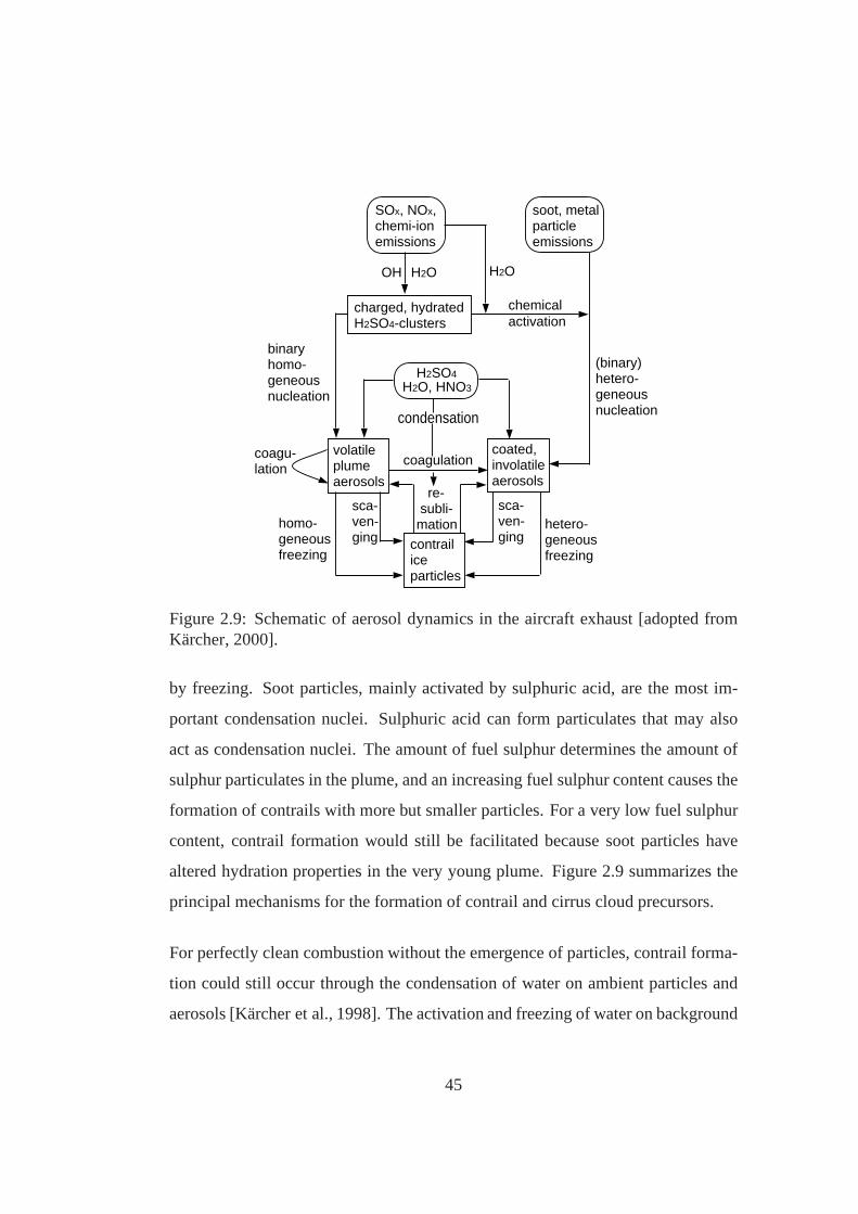
SOx, NOx,chemi-ionemissions
charged, hydratedH2SO4-clusters
H2SO4H2O, HNO3
soot, metalparticleemissions
volatileplumeaerosols
coated,involatileaerosols
contrailiceparticles
OH H2O
chemicalactivation
(binary)hetero-geneousnucleation
H2O
binaryhomo-geneousnucleation
coagu-lation
homo-geneousfreezing
hetero-geneousfreezing
sca-ven-ging
sca-ven-ging
coagulation
re- subli-mation
condensation
Figure 2.9: Schematic of aerosol dynamics in the aircraft exhaust [adopted fromKarcher, 2000].
by freezing. Soot particles, mainly activated by sulphuricacid, are the most im-
portant condensation nuclei. Sulphuric acid can form particulates that may also
act as condensation nuclei. The amount of fuel sulphur determines the amount of
sulphur particulates in the plume, and an increasing fuel sulphur content causes the
formation of contrails with more but smaller particles. Fora very low fuel sulphur
content, contrail formation would still be facilitated because soot particles have
altered hydration properties in the very young plume. Figure 2.9 summarizes the
principal mechanisms for the formation of contrail and cirrus cloud precursors.
For perfectly clean combustion without the emergence of particles, contrail forma-
tion could still occur through the condensation of water on ambient particles and
aerosols [Karcher et al., 1998]. The activation and freezing of water on background
45
particles would lead to contrails consisting of less but larger particles, and contrail
formation would require slightly lower ambient temperatures.
2.1.3 Radiative forcing of contrails
Aerosols and contrails have direct and indirect effects on the climate. The direct
effects include scattering and absorbing radiation, the indirect effects include mod-
ifying the formation of cloud particles and changing the properties of clouds.
In general, contrails are ice clouds with radiative properties similar to thin cirrus
clouds. The radiative forcing of contrails can be broken down into shortwave radia-
tive forcingRFSW and long wave radiative forcingRFLW. The short wave radiative
forcing denotes the solar energy flux prevented from entering earth’s upper tro-
posphere. Long wave radiative forcing is the energy flux of terrestrial radiation
prevented from leaving the earth. The net radiative forcingis the sum of both,
longwave and shortwave radiative forcing.
RFtotal = RFLW +RFSW (2.5)
In Meerkotter et al. [1999], a one dimensional radiative transfer model was used to
quantify the sensitivity of contrail parameters regardingits radiative forcing.
The short wave radiative forcing of ice clouds is determinedby the solar zenith
angle, the earth’s surface albedo and its optical depth. It has a higher magnitude
over dark surfaces than over deep blue oceans. Soot immersedin or attached to
contrail ice particles may increase the absorption of solarradiation, thus reducing
the albedo of contrails.
46

The longwave radiative forcing of ice clouds depends on the emissivity of its par-
ticles. It increases with the ice path, which is the product of contrail depth and ice
water content. The longwave radiative forcing of ice cloudsis maximum for clear
sky conditions, a warm earth’s surface and low humidity of the air below the con-
trail. Strong longwave radiative forcing can be found over tropic regions or oceans.
Contrails with smaller particles tend to cause a stronger positive net radiative forc-
ing, because small ice crystals enhance the cloud’s albedo to a lesser extent than its
emissivity. However, for contrails with very small particles, the effect is reversed.
Meerkotter et al. [1999] concluded that contrails cause a heating at the top of atmo-
sphere for the majority of scenarios. An overall negative radiative forcing is pos-
sible for contrails over very cold surfaces with low ground albedo, or over a very
humid but cloud free troposphere. The positive net forcing of ice clouds grows with
increasing optical depth, but becomes negative with very large optical depth, larger
than that of typical contrails. Contrails have the largest radiative forcing during
night, when the short wave radiative forcing is not existentand only the long wave
forcing remains [Stuber et al., 2006]. Over mid-latitudes,the radiative forcing of a
contrail is larger during the summer than during the winter because of variations in
the diurnal solar flux and the solar zenith angle.
The main parameter determining the global radiative forcing of contrails is the
contrail cover, determining the amount of area covered by contrails. It is estimated
that the global cover by line-shaped contrails is 0.1% [Schumann, 2002].
2.1.4 Wake dynamics
During cruise conditions, the aircraft wake is composed of vortices, and the two
counter-rotating wing tip vortices are predominant. Theseinteract with the engine
47

exhaust jets, having an effect on the formation, dispersionand persistence of con-
trails.
The evolution of the interaction of the engine exhaust with the aircraft wake is
categorized into three sequential regimes [Brunet et al., 1999, Jacquin and Garnier,
1996]: a) the jet regime, dealing with the near field of the engine jet, is equivalent
to that of usual co-flowing jets (for two engine aircraft it istwo jets); b) the deflec-
tion regime corresponds to the entrainment and capture of the jet by the wing tip
vortices; c) the shearing regime, during which the plume is affected by shearing
and convection as a result of the rotational velocity component inside the vortex
cores.
Paoli and Garnier [2005], Paoli et al. [2004] combined a two phase flow and mi-
crophysics model to simulate the near field interaction of a trailing vortex with
an exhaust jet during the deflection regime. Results suggestthat cooling and va-
por condensation are enhanced by the entrainment of the exhausts by the wing tip
vortices.
Computational large eddy simulations were carried out in numerous studies to in-
vestigate the jet interactions during the shearing regime.In general, a pair of
counter rotating vortices creates a flow field that results inthe movement of the
vortex pair. For wing tip vortices, the circulation field induces a downwards mo-
tion, resulting in quasi-adiabatic compression of the vortices as they descend to
lower altitudes where higher pressures prevail. Aircraft vortices interacting with
any ambient shear can also touch, reconnect and form descending vortex rings, a
phenomenon known as Crow instability [Crow, 1969]. The compression causes an
increase in temperature of the vortices, resulting in buoyancy forces that diminish
the descent velocity of the vortex pair [Lewellen and Lewellen, 2001, Proctor et al.,
1997]. Gierens and Jensen [1998] concluded that heating dueto adiabatic compres-
48

sion of a falling vortex system can lead to significant ice crystal number depletion
depending on the ambient ice-supersaturation, ice crystalnumber density and wake
characteristics.
Huebsch and Lewellen [2006] calculated that in the presenceof atmospheric turbu-
lence, a marginally more effective mixing of ambient air with the aircraft exhaust
takes place, whereas high turbulence levels in the atmosphere cause an increase
in contrail ice crystal number and overall ice mass. Higher ambient temperature
lapse rates, or stratification, prevent the descent of contrails, and hence dimin-
ish adiabatic heating, which results in more ice particles remaining in the con-
trail compared to the case where no stratification prevails [Huebsch and Lewellen,
2006, Lewellen and Lewellen, 2001]. Work by Huebsch and Lewellen [2006] and
Chlond [1998] suggests that ice particle evaporation is only marginally affected
by ambient wind shear. Lower levels of initial ice particle number density have
the effect of the formation of larger particles, whereas higher levels of ice particle
number density yield smaller ice particles [Huebsch and Lewellen, 2006]. If more
but smaller ice particles exist in the plume, it is more likely that they will evaporate
during the adiabatic heating associated with vortex descent.
The strength of the wing tip vortices determines the evolution of the contrail. An
analysis of wake vortex decay mechanisms is given in Holzapfel et al. [2003],
where it was concluded that a decrease of the normalized spacing of two vortices
may accelerate their decay, whereas increasing the vortex radii at constant spacing
reduces their lifetime.
An effective entrainment of the engine exhaust jets enhances the vertical extension
of a contrail, potentially increasing the probability for acontrail to cirrus transition.
Unfortunately, contrail dispersion and ice particle evaporation are in conflict with
each other. Huebsch and Lewellen [2006] found that engines placed placed further
49
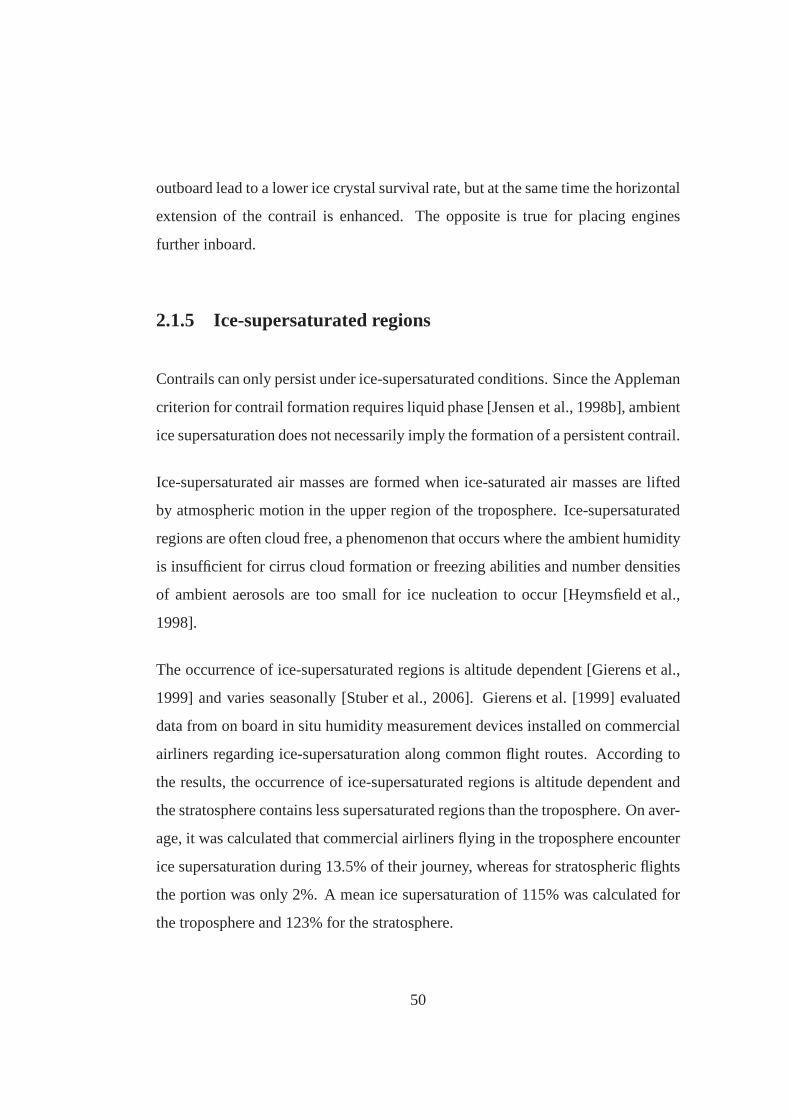
outboard lead to a lower ice crystal survival rate, but at thesame time the horizontal
extension of the contrail is enhanced. The opposite is true for placing engines
further inboard.
2.1.5 Ice-supersaturated regions
Contrails can only persist under ice-supersaturated conditions. Since the Appleman
criterion for contrail formation requires liquid phase [Jensen et al., 1998b], ambient
ice supersaturation does not necessarily imply the formation of a persistent contrail.
Ice-supersaturated air masses are formed when ice-saturated air masses are lifted
by atmospheric motion in the upper region of the troposphere. Ice-supersaturated
regions are often cloud free, a phenomenon that occurs wherethe ambient humidity
is insufficient for cirrus cloud formation or freezing abilities and number densities
of ambient aerosols are too small for ice nucleation to occur[Heymsfield et al.,
1998].
The occurrence of ice-supersaturated regions is altitude dependent [Gierens et al.,
1999] and varies seasonally [Stuber et al., 2006]. Gierens et al. [1999] evaluated
data from on board in situ humidity measurement devices installed on commercial
airliners regarding ice-supersaturation along common flight routes. According to
the results, the occurrence of ice-supersaturated regionsis altitude dependent and
the stratosphere contains less supersaturated regions than the troposphere. On aver-
age, it was calculated that commercial airliners flying in the troposphere encounter
ice supersaturation during 13.5% of their journey, whereasfor stratospheric flights
the portion was only 2%. A mean ice supersaturation of 115% was calculated for
the troposphere and 123% for the stratosphere.
50

li
Figure 2.10: Relative ice supersaturation frequency [adopted from Mannstein et al.,2005].
The vertical extent of ice-supersaturated regions is relatively small compared to
their horizontal extent. Radiosonde data was used in Mannstein et al. [2005] to
calculate the relative ice-supersaturation frequency depending on a relative change
in flight altitude. It was concluded that if aircraft encountering ice-supersaturation
changed cruise altitude by less than 1000 metres toward the nearest ice-subsaturated
altitude, 99% of ice supersaturation could be avoided. Figure 2.10 shows the ice-
supersaturation frequency depending on a change in cruise altitude.
2.2 Contrail cirrus clouds
Contrails formed in a low ice-supersaturated atmosphere would persist but remain
limited in size and lifetime [Schroder et al., 2000]. Contrails formed in regions
51

with high prevailing ice-supersaturation may spread and transform into large area
cirrus clouds, so called contrail cirrus [Jensen et al., 1998b, Minnis et al., 1998].
A line shaped contrail in an environment where the wind speedvaries over altitude
will spread as ice particles in the upper part of the contrailare carried away at a
different speed than the ice particles of the bottom part of the contrail. The altitude
dependent variation in wind speed, commonly referred to as wind shear, is the
dominating effect in the horizontal spreading of contrails. The vertical extent of
contrails also plays a role in the transition from line shaped contrails to contrail
cirrus. For increasing vertical extent of the contrail, thedifference in wind speed
between the top and bottom part of the contrail becomes larger, resulting in faster
transition rates.
The vertical spreading of the contrail results from the precipitation of larger ice par-
ticle to lower altitudes, updrafts caused by radiative heating inside the contrail, and
aircraft wake dynamics. Ice-supersaturated regions are primarily linked to synoptic
conditions that support vertical motions of air, also having an effect of the vertical
extent of the contrail.
Large eddy simulations have been carried out by Jensen et al.[1998a] to simulate
the evolution of a contrail. Results suggest that ambient supersaturation leads to
increased contrail ice particle growth rates near the contrail’s edges. Supported by
vertical air motions, larger ice particles fall most rapidly resulting in a size sorting
with height. Contrail spreading is less severe for low ambient supersaturation be-
cause it reduces ice particle growth rates and thus precipitation. The simulation of
the vortex phase and dispersion phase of a contrail from a B747 aircraft is described
in Gierens and Jensen [1998]. The study involves complex aircraft wake dynamics
microphysics modeling to account for ice nucleation. The simulations suggest that
the initial wing vortex pattern breaks up into two structures in which one structure is
52

evaporating due to adiabatic heating during descent. The second structure extends
downwards, and the surviving ice particles grow, forming a persistent contrail. The
cold layer above the cloud causes buoyancy causing an ascentof the cloud in a
warmer and stably stratified region. Thereafter, the cloud spreads out horizontally
and breaks into several fragments, mixing into the dry air and finally evaporates.
The cloud coverage by cirrus clouds resulting from contrails has a considerable
time lag behind the air traffic. In regions where air traffic ispredominantly taking
place during day time, contrail cirrus occurrences are shifted to night hours where
only the long wave radiative forcing remains [Mannstein andSchumann, 2005].
It is suggested that the radiative forcing caused by aviation induced cirrus clouds
has the potential to be several times stronger than that of line shaped contrails.
2.3 Secondary cirrus clouds
Karcher and Lohmann [2003] concluded that aviation can cause an increase of soot
particle number concentration by more than 30% in regions highly frequented by
aircraft. Soot and also aerosol emissions from aircraft have the potential to cause
the formation of cirrus clouds where no cirrus clouds would form naturally. An
evaporated contrail ice particle can leave traces of ice attached to the condensa-
tion nucleus unless exposed to a dry environment for a long time. These particles
are more likely to re-nucleate under supersaturated conditions, an effect known as
preactivation [Karcher and Lohmann, 2003, Pruppacher andKlett, 2000]. Preacti-
vation enhances the freezing ability of aircraft soot particles that acted as threshold
contrail condensation nuclei.
Satellite and surface observations show a statistically significant dependency be-
53

tween cirrus cover and air-traffic density [Minnis et al., 2001, Stordal et al., 2004,
Zerefos et al., 2003a]. Cirrus clouds nucleating on aircraft particle and aerosol
emissions occur independently from contrails and contrailcirrus and would not
form in the absence of air traffic. They are commonly referredto as secondary
cirrus clouds and contribute to the overall cloud cover, yielding a positive radiative
forcing.
2.4 Natural cirrus modification
Aircraft emissions may also cause an indirect climate forcing by changing particle
size and ice particle number density of natural cirrus clouds. It has been observed
that the effective ice crystal diameter decreases and the ice crystal number density
is enhanced in cirrus clouds perturbed by aircraft soot [Kristensson et al., 2000].
These modification impact the micro-physical properties ofcirrus clouds, the ice
particle size, geometry and cloud life-time. According to Meerkotter et al. [1999],
perturbed natural cirrus clouds can have a stronger radiative forcing. Natural cirrus
modification by aircraft emissions depend on the nucleationability of the exhaust
particles. The effect is less severe in regions where the formation of natural cirrus
clouds occurs on more efficient ice nuclei than that of the aircraft exhaust particles.
2.5 Aerodynamic contrails
Pressure disturbances around the lifting surfaces and turbulence in the aircraft wake
can initiate condensation of water on particles. In the caseof ambient ice supersat-
uration, this will cause a persistent linear contrail with similar radiative properties
54

to that of engine induced contrails.
Gierens and Strom [1998] calculated that adiabatic cooling as it occurs within the
complex flow field of an aircraft wake can triggering homogeneous freezing nu-
cleation. The results suggested that the formation of aerodynamic contrails occurs
more likely for aircraft with increased wing span. Especially heavy, slow, wide-
body aircraft would favour the formation of aerodynamically induced contrails.
55

Chapter 3
Contrail avoidance strategies
In this section, contrail avoidance strategies are presented. In the majority of cases,
the strategies were derived from the literature survey and developed during the
work programme in several studies, whereas some strategiescould be found in the
public domain in the form of journal publications or patents, in which case sources
are referred to appropriately.
In order to develop strategies that have the potential to mitigate the radiative forc-
ing of contrails, an integrated framework for the identification of strategies was
deduced from the literature survey. It is subdivided into four levels of coherency:
radiative forcing→ contrail occurrences and radiative properties→ physical prin-
ciples→ technological and operational enablers. The radiative forcing of contrails
on a global scale can be directly linked to both contrail occurrences and their radia-
tive properties, whereas the principles determining contrail occurrences or radiative
properties can be attributed to one of the following identified categories:
Particles & aerosols: particles and aerosols provide condensation nuclei for con-
56

trails and secondary cirrus clouds, and activate hydrophobic particles. They
affect the formation and the radiative properties of contrails.
Wake dynamics: near field and far field interaction of the engine exhaust with
the aircraft wake facilitates the mixing of the exhaust withambient air. The
evolution and interaction of the wake with the atmosphere has an effect on
the development of the contrail and its transition into a contrail cirrus. Wake
dynamics influence the formation of aerodynamic contrails.
Contrail potential: the condensation of water occurs only in the case of liquid
supersaturation occurring within the plume, facilitated through the mixing
of the exhaust gases with ambient air or triggered by humidity, pressure and
temperature variations in the aircraft wake.
Air-traffic distribution: the radiative forcing of contrails, contrail occurrences,
and contrail persistence depend on the temporal and spatialdistribution of
aircraft routes.
Operational and technological enablers are engineering tools that enable the reduc-
tion of the environmental impact from contrails. They function according to at least
one of the afore-mentioned principles and can be attributedto at least one of the
following groups:
Engine architecture: includes all possible modifications to the propulsion de-
vice, or novel and revolutionary concepts.
Flight path: modifications to the spatial and temporal characteristics of the flight
path trajectory of a single aircraft, the air traffic for a region or the air traffic
on a global scale.
57

Fuel and combustion: addresses emission control, the type of energy source used
to power the propulsion device, and the conversion method ofstored energy
into any other form of energy required to obtain a propulsiveforce.
Airframe and engine integration: all modifications to current technology or novel
concepts regarding the airframe and the engine integrationmethod.
Supplementary devices: devices which prevent by any means the formation of
contrails, contrail cirrus or aviation induced cirrus clouds.
A graphical representation of the framework for the identification of contrail avoid-
ance strategies is given in figure 3.1. A change in the radiative forcing from con-
trails (green) can be achieved via the technological enablers (blue), which accord-
ing to the different physical principles (yellow) have an impact on the radiative
properties or occurrences of contrails (red). Connectionswhere an interdepen-
dency can be assumed but has not been proven yet are indicatedby a dashed line.
3.1 Adjustment of air traffic
The underlying idea is to adjust air traffic to avoid regions which support the forma-
tion of persistent contrails or which because of their geographical location cause a
positive radiative forcing of contrails. In a preliminary study, the geographical dis-
tribution of regions facilitating contrail formation was investigated. Therefore, the
probability for contrail formation was calculated on a global scale using MetOffice
weather data. The data, containing records for the year 2005, comprises informa-
tion regarding temperature and humidity in a 6 hour intervalon a global grid. A
description of the data can be found in the appendix on page 157. For each grid
58

Figure 3.1: Integrated framework of interdependencies in the contrail formationprocess to identify contrail avoidance strategies.
cell and time interval, it was computed whether the formation of a persistent con-
trail was facilitated by testing for ice supersaturation and whether the Appleman
criterion, as described in section 2.1.1, is satisfied. Events where the formation of
persistent contrails was facilitated were counted and divided by the number of time
intervals, yielding the probability for contrail formation for each grid cell. Results
presented hereafter are based on calculations where an aircraft overall efficiency of
0.4 was assumed.
Figure 3.2 shows the probability for contrail formation at different pressure levels.
It can be seen that at low altitudes, contrail formation is more likely to occur to-
wards the poles, whereas at higher altitudes, the probability for contrail formation is
increasing towards the equator. According to the results, contrail formation is most
59
me080819
Rectangle
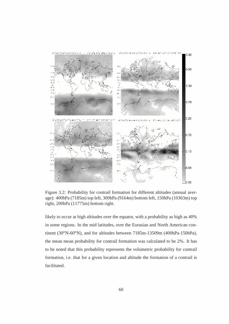
Figure 3.2: Probability for contrail formation for different altitudes (annual aver-age): 400hPa (7185m) top left, 300hPa (9164m) bottom left, 150hPa (10363m) topright, 200hPa (11775m) bottom right.
likely to occur at high altitudes over the equator, with a probability as high as 40%
in some regions. In the mid latitudes, over the Eurasian and North American con-
tinent (30oN-60oN), and for altitudes between 7185m-13509m (400hPa-150hPa),
the mean mean probability for contrail formation was calculated to be 2%. It has
to be noted that this probability represents the volumetricprobability for contrail
formation, i.e. that for a given location and altitude the formation of a contrail is
facilitated.
60

Figure 3.3: Areal probability for contrail formation for anoverall engine efficiencyof 0.4.
engine efficiency 0.3 0.4 0.5probability 11.8% 12.9% 14.5%
Table 3.1: Global average area probability for contrail formation.
The area potentially being covered by contrails, also referred to as the potential
contrail cover, is regardless of the altitude at which the contrail occurs, and the
global average area probability that contrail formation isfacilitated was calculated
in a separate set of computations. As it varies depending on the assumed overall
engine efficiency, it was carried out for different values ofoverall engine efficiency.
Results are given in table 3.1, and the potential contrail cover was calculated to
be 11.8-14.5%, depending on the overall engine efficiency. Figure 3.3 shows the
potential contrail cover assuming the overall engine efficiency to be 0.40. For the
northern hemisphere over regions with high air traffic density, the potential contrail
cover was calculated to be in the range of 17%.
Considering that the occurrence of regions facilitating the formation of contrails
61

varies geographically, temporarily and with altitude, thespatial or temporal adjust-
ment of air traffic could lead to the reduction of contrail occurrences. Furthermore,
as described in section 2.1.3, the radiative forcing of contrails is dependent on the
ground albedo and daytime. Hence, the spatial or temporal adjustment of air-traffic
could not only yield a reduction of contrail occurrences, but also a reduction in the
radiative forcing of contrails independently from their occurrences. In the light of
this fact, the adjustment of air traffic in its various ways was investigated.
3.1.1 Temporal adjustment of air traffic
Temporal adjustment of air traffic to reduce the environmental impact from con-
trails can be applied to either avoid aircraft flying throughregions in the atmosphere
that facilitate the formation of persistent contrails or tocause contrail occurrences
when their radiative forcing is minimum.
The radiative forcing of contrails varies over the day because of diurnal varia-
tions in solar radiation at a particular location on the globe. During night times,
in the absence of solar radiation, only outgoing long wave radiation is affected
by contrails. Since the overall radiative forcing of contrails is the sum of both
longwave and shortwave radiation, and the solar forcing is negative, the overall ra-
diative forcing is increased during night. Stuber et al. [2006] concluded that night-
time flights during winter are responsible for most of the contrail radiative forc-
ing and according to Myhre and Stordal [2001], an increase inair-traffic density
around sunrise and sunset would reduce the radiative forcing of contrails. How-
ever, this might be in conflict with the fact that secondary cirrus from contrails
formed during evening hours persist during night when they cause a stronger radia-
tive forcing [Mannstein and Schumann, 2005], an effect thatwas not considered by
Myhre and Stordal [2001]. Although the approach exhibits environmental benefits
62

in terms of contrail radiative forcing, it implies the limitation of air traffic to morn-
ing and evening hours, which from an economical point of viewis regarded to be
impractical. Air traffic is currently taking place during the entire day, and limit-
ing air traffic to certain periods would not be in the interestof airline customers
and very likely yield airport and air corridor congestion during the times when air
traffic is taking place. Hence, this approach was not pursuedfurther.
3.1.2 Spatial adjustment of air traffic
Similar to the temporal adjustment of air traffic, spatial adjustment of air traffic or
individual flights could be applied to either avoid aircraftflying through regions in
the atmosphere where the formation of contrails is facilitated, or to cause contrail
occurrences where their radiative forcing is minimal.
As the surface albedo determines the radiative forcing of contrails, contrails over re-
gions with low ground albedo would reduce their radiative forcing [Meerkotter et al.,
1999]. Hence, avoiding flights over regions with high groundalbedo would reduce
the radiative forcing of contrails. As regions with an albedo required to reduce the
environmental impact of contrails cannot be found near all airports, the approach is
impractical as it can only be applied to limited amount of flight routes. It has also
to be taken into account that contrails, once formed, can travel over large distances,
depending on the high wind speed at high altitudes. Hence, although a contrail
might have formed over a region with low albedo, it could be found over a region
with high albedo after some time has passed. Furthermore, inorder to divert flights
over regions with low albedo, the flight path would be artificially prolonged, lead-
ing to fuel burn penalties and and increase in journey time. In the light of these
disadvantages, the approach was seen as impractical and hasnot been investigated
in more detail.
63

Apart from adjusting air traffic to reduce the radiative forcing from contrails, con-
trail occurrences could be reduced by preventing aircraft from flying through re-
gions in the atmosphere that facilitate the formation of persistent contrails. Regions
susceptible to the formation of contrail cirrus have distinguishable characteristics
and could be avoided independently.
An aircraft approaching a region that facilitates contrailformation could avoid it by
either changing altitude or diverting from the flight path horizontally. The horizon-
tal deviation from the flight path would imply an increase in flight length, leading
to higher block fuel consumption, and as the aircraft performance is dependent on
flight altitude, a change in cruise altitude would also implyan increase in fuel burn.
The most fuel efficient altitude of a conventional commercial aircraft increases as
the journey progresses. Calculations were performed to calculate the effect of a
change in cruise altitude on fuel consumption and contrail formation. Therefore,
TURBOMATCH and the ESDU aircraft performance were embeddedin a MAT-
LAB script. A description of the codes can be found in the appendix on page 156.
The aircraft type considered in the study is a modern long-haul medium-size com-
mercial transport aircraft, as described in the appendix onpage 157. The baseline is
used in all calculations throughout this thesis. Figure 3.4shows the relative change
in specific block fuel consumption in fuel per passenger-kilometre, also known as
inverse specific air rnage (ISAR), depending on altitude andcruise speed for dif-
ferent aircraft weight and ISA temperature deviation scenarios. Displayed true air
speeds correspond to a Mach number range of 0.75 to 0.85. The ISAR is minimum
for a certain altitude-speed combination. For higher/lower speeds and altitudes, the
aircraft operates outside the most fuel efficient conditions, and the most fuel effi-
cient cruise altitude is increasing as the fuel weight decreases (from left to right in
figure 3.4).
The horizontal lines in figure 3.4 denote altitudes for persistent contrail formation
64

according to the Appleman criterion. At low altitudes belowthe dash-dotted line,
contrail formation is not facilitated. For altitudes between the upper dashed and
lower dash-dotted lines, contrail formation depends on theambient humidity, de-
noted by the dashed lines in between: 140% (bottom), 120% (middle) and 100%
(top). Contrail formation is always facilitated for altitudes above the top dashed
line.
Changing to lower speeds has an impact on the overall engine efficiency. Figure
3.5 shows the absolute change in engine efficiency. Althoughthe associated loss
in overall engine efficiency could be seen as a method to avoidthe formation of
contrails, the decrease in engine efficiency is marginal, atmost 3% for the range
shown in figure 3.5, with almost no effect on contrail formation.
Hence, changing cruise altitude would be more effective foravoiding contrail for-
mation. However, the specific block fuel consumption of the considered aircraft
type is minimum for altitudes where contrail formation is facilitated. This is es-
pecially the case for a negative ISA temperature deviation and low aircraft weight.
In order to avoid contrail formation thermodynamically, anaircraft would have
to change to lower cruise altitudes where the ambient temperature and the spe-
cific block fuel consumption is higher. In the case of zero ISAtemperature de-
viation and 66% fuel in the tanks, an aircraft operating at its most fuel efficient
altitude/cruise speed combination (250m/s at 10750m) would have to descend by
1500 metres to avoid contrail formation. This would be accompanied with an in-
crease in specific block fuel consumption of about 5%. However, formation of
persistent contrails is only facilitated if the ambient atmosphere is ice supersatu-
rated, and ice-supersaturated regions can have a vertical extent that would be lower
than the required altitude change to avoid contrail formation thermodynamically,
resulting in a less severe increase in block fuel consumption.
65

Tisa
= -2.5K, 100% fuel
220 230 240 250 2608000
8500
9000
9500
10000
10500
11000
Tisa
= -2.5K, 66% fuel
220 230 240 250 2608000
8500
9000
9500
10000
10500
11000
Tisa
= -2.5K, 33% fuel
220 230 240 250 2608000
8500
9000
9500
10000
10500
11000
altitude [
m]
Tisa
= 0K, 100% fuel
220 230 240 250 2608000
8500
9000
9500
10000
10500
11000
Tisa
= 0K, 66% fuel
220 230 240 250 2608000
8500
9000
9500
10000
10500
11000
Tisa
= 0K, 33% fuel
220 230 240 250 2608000
8500
9000
9500
10000
10500
11000
Tisa
= +2.5K, 100% fuel
220 230 240 250 2608000
8500
9000
9500
10000
10500
11000
true air speed [m/s]
Tisa
= +2.5K, 66% fuel
220 230 240 250 2608000
9000
10000
11000
Tisa
= +2.5K, 33% fuel
220 230 240 250 2608000
9000
10000
11000
2
4
6
8
10
12
14
140%120%100%
always
nevercontrails
contrails
Figure 3.4: Relative change in inverse specific air range relative to most fuel eco-nomic value [%].
Three distinct approaches were identified that can be used tomitigate the formation
of contrails by spatially adjusting air traffic: (a) change cruise altitude on a global
scale [Fichter et al., 2005]; (b) restrict cruise altitudesbased upon atmospheric con-
ditions for certain regions over a certain time period [Williams and Noland, 2005];
(c) change aircraft cruise altitude during flight dependingon ambient conditions
[Mannstein et al., 2005]. These approaches are discussed inthe following.
(a) change cruise altitude on a global scale
Ambient temperature, pressure and humidity depend on altitude and differ geo-
graphically. If air traffic was shifted upwards or downwardsrelative to current
66

Figure 3.5: Absolute change in overall engine efficiency.
typical cruise altitudes, a change in contrail occurrences, and hence radiative forc-
ing, should be observable. The stratosphere e.g. is much drier than the troposphere
[Gierens et al., 1999], and stratospheric air traffic would reduce contrail cover con-
siderably. However, other considerations would have to be taken into account.
There are concerns about ozone depletion by nitrogen oxidesdue to stratospheric
air traffic.
In Fichter et al. [2005], a parametric analysis of the radiative forcing from contrails
depending on a shift of air traffic to different altitudes is presented. In that study,
the global radiative forcing of contrails was calculated bymeans of a global circu-
lation model for different air-traffic scenarios. It was calculated that a downwards
displacement of the flight corridors on a global scale would result in a decrease in
global contrail coverage and radiative forcing, especially during the winter months.
67

(a) Contrail cover. (b) Radiative forcing.
Figure 3.6: Change in contrail cover and radiative forcing from contrails by chang-ing flight altitude [adopted from Fichter et al., 2005].
An increase in contrail cover would occur in regions with prevailing high altitude
air traffic in the mid-latitudes. The opposite would be true for an upwards shift of
the flight corridors. Figure 3.6 shows the change in contrailcover and the associ-
ated radiative forcing for different altitude scenarios. An increase in fuel burn of
6.3% was calculated for the case of shifting air traffic 6,000feet downwards.
In general, aircraft are designed for a particular mission in terms of cruise speed,
payload and journey length. Depending on the technology, the most economic
cruise altitude results from the initial specification. If an aircraft designed for a
particular altitude is flying above or below that altitude, more fuel is required to
complete the journey and hence more carbon dioxide is emitted. In addition, some
journeys would not be feasible due to the limited fuel capacity and minimum climb
requirements during take off. However, aircraft especially designed for different
altitudes might offset the fuel burn penalty, an issue investigated in section 3.3.1.
68

(b) restrict cruise altitudes based upon atmospheric conditions for certain re-
gions over a certain time period
In this approach, air traffic is shifted to different flight corridors for defined regions
and over a certain time period. Williams and Noland [2005] carried out simula-
tions for air traffic over Europe. In the simulations, air-traffic corridors were relo-
cated in 6 hour intervals depending on atmospheric conditions, and the formation
of contrails was assessed using atmospheric data. Results suggest that (b) leads
to a decrease in contrail cover of 65-95%, associated with a fuelburn penalty of
2.6-7.0%.
However, air-traffic management and safety issues associated with this contrail
avoidance method may impede its application. Currently, aircraft are allocated cer-
tain flight altitudes to avoid collision with other aircraft, and the allocated flight al-
titudes can be found within certain flight levels. Aircraft changing altitude in flight
would cause a rise in traffic on other flight levels, increasing the risk of collision.
Especially regions with heavy air traffic would be affected.Williams and Noland
[2002] studied the increase in air traffic associated with this contrail avoidance
method and found that the required minimum separation between aircraft could
not then be maintained due to the reduced number of availableflight levels. In a
following study, [Noland and Williams, 2003] concluded that this could be allevi-
ated by redesigning air-traffic sectors.
(c) change aircraft cruise altitude during flight depending on ambient condi-
tions
Regions that facilitate the formation of persistent contrails could be avoided by
changing cruise altitude in flight. This technique is already applied by military
69

planes to suppress their visibility. Since the deviation from the most fuel efficient
cruise altitude would be for a relatively short time period,the fuel burn penalty is
expected to be lower than for (a) and (b).
The flight path could be planned already prior to take off. Weather forecast data or
in-flight measurements of preceding aircraft could be used to determine the flight
path that facilitates a reduction in contrail formation. Ifforecast data or in flight
measurements lack the required accuracy, an alternative approach would be on-
board sensors, which can detect the formation of contrails behind the aircraft. Hu-
midity, pressure and temperature measurements could complement measurements
to enable effective decision-making by the pilot whether tochange altitude or not.
As for (b), this contrail avoidance method could lead to an increasing risk for air-
craft collision. More sophisticated flight tracking and collision avoidance systems
would be required for an introduction of this contrail avoidance strategy.
The fuel burn penalty that comes with changing altitude during flight was assessed
in a study as part of the PhD project. Therefore, a MATLAB script was developed
that allows the optimization of a flight path between a specified departure and des-
tination point for minimum contrail formation. Starting with the great circle route,
the flight path was parameterized subdividing it into equally long portions. A hori-
zontal and vertical offset of waypoints from the great circle route could be defined,
yielding in a flight path differing from the great circle route. Fuel consumption
along the flight route was calculated considering change in aircraft weight as fuel
is consumed and the change in performance of the aircraft depending on altitude
was taken into account. Therefore, engine performance response surfaces were
created with TURBOMATCH. The response surfaces were used inthe ESDU air-
craft point performance code, which was embedded in the MATLAB script. For
each waypoint, the ESDU aircraft point performance code wascalled to get the
fuel flow rates. Time integration of the fuel flow rates yieldsoverall block fuel con-
70

sumption. In between the major waypoints, additional waypoints could be defined
to increase the accuracy of fuel burn figures. In order to account for contrail forma-
tion, the probability for persistent contrail formation was calculated for each month
using the 2005 operational weather analysis data of the MetOffice unified model.
Defining departure and destination coordinates, the geographic location and alti-
tude was known for each waypoint. The MATLAB script reads theprobability for
contrail formation at each waypoint, which allowed the calculation of the fraction
of the flight path where contrail formation is facilitated. Linear interpolation was
applied in between the available grid points.
Varying the offsets of the waypoints from the great circle route would result in both
a change in fuel burn and the fraction of the flight path where contrail formation
is facilitated. The MATLAB script was connected to a commercially available
simplex optimisation algorithm. The objective of the optimisation was to minimize
fuel burn and reducing the fraction of the flight path where contrail formation is
facilitated. Therefore, an objective function was selected which combines both
fuel consumption and contrail formation in the form
OBJ= mf uel [cw pi +1] (3.1)
wheremf uel is the mass of the fuel burned during the journey,cw is a weighting
factor andpi the fraction of the flight path where contrail formation is facilitated.
In this study, the flight path was defined by 8 major waypoints,and the considered
departure and destination points were London and New York, stretching over a dis-
tance of approximately 5600km. In the first instance, the fuel burn and amount
of contrail km formed was calculated for the great circle route without taking into
account contrails formation, i.e. cw = 0. Fixing the weighting factor to 6, optimi-
sations were then carried out for each month. Figure 3.7 contains results regarding
the fraction of the flight path where contrail formation is facilitated for the contrail
71

J F M A M J J A S O N D0
1
2
3
4
5
6
7[%
]contrails with avoidance
contrails w/o avoidance
rel. increase fuel burn
Figure 3.7: Annual variation in contrail formation along the flight path with andwithout avoidance and the relative increase in fuel burn.
avoidance and non-avoidance scenario, and the associated increase in fuel burn.
According to the results, the annual mean of the fraction of the flight path where
contrail formation is facilitated is 3.7%. Numbers peaked during the winter months
and were lower during the summer months. Applying flight pathoptimisation, a
reduction in contrail formation was possible but associated with a fuel burn penalty.
The new mean fraction of the flight path where contrail formation is facilitated was
calculated to be 0.8%, which is a 78% decrease in contrail occurences in absolute
terms. The relative increase in fuel burn was calculated to be 0.8%.
Allowing the change of cruise altitude in flight, also calledfree flight, does not only
have advantages because the formation of contrails could beavoided. It would also
allow continuous climb, an approach often suggested to reduce fuel burn, and hence
CO2 emissions. Free flight has been established as one of the mostcommonly
mentioned approaches for contrail avoidance [Dings and Peeters, 2000]. But it is,
72

EI cp M qnet
1.25 1004J/(kgK) 0.622 43MJ/kg
Table 3.2: Parameters for minimum engine efficiency calculations.
however, associated with severe implications regarding air-traffic management and
safety. Otherwise its introduction would have probably already happened as it ex-
hibits the potential to reduce fuel burn, which would not only reduce CO2 emissions
but also reduce airline direct operating costs.
3.2 Engine technology
For a given ambient temperature, pressure and humidity, theminimum engine ef-
ficiency required for contrail formation can be calculated solving equation 2.3.
Ambient temperature and pressure is a function of altitude,described by the In-
ternational Standard Atmosphere (ISA) atmospheric model.Hence, the minimum
engine efficiency required for contrail formation can be calculated specifying alti-
tude and ambient ice-supersaturation and, if desired, a temperature deviation from
the ISA atmosphere. Calculations were conducted combiningequation 2.2 with the
standard atmosphere model. The parameters used for the calculation are given in
table 3.2, and results for different overall aircraft efficiencies are shown in figure
3.8. They can be used to determine the minimum overall engineefficiency required
to facilitate the formation of contrails. For example, at analtitude of 8500 metres
and a local ice-supersaturation of 140%, aircraft with an overall efficiency of 0.4
or more would cause the formation of contrails. With a negative ISA temperature
deviation, the minimum overall engine efficiency required for contrail deviation
decreases and the opposite is the case for a positive ISA temperature deviation.
In general, the minimum engine efficiency required to facilitate contrail formation
73

Figure 3.8: Minimum engine efficiency required for contrailformation for standardtemperature deviations±2.5K.
increases for altitudes and levels of ice-supersaturation. Current aircraft, typically
operating with overall efficiencies of 0.30-0.35, do not facilitate contrail formation
for altitudes below 9500 metres assuming an ice-supersaturation below 130%. Air-
craft designed with higher overall efficiencies, say 0.5, would cause no contrails if
they flew below 8300 metres (7750m if the ISA temperature deviation was -2.5K).
However, it is important to note that the occurrences for ice-supersaturated regions
is altitude dependent, and lower altitudes does not necessarily mean less contrails
on a global scale.
Referring to equation 2.2, lower values of the mixing line slopeσ, reducing the
74

potential for contrail formation, can be obtained by eitherdecreasing its numerator
or increasing its denominator. The variables in the numerator arecp, EIwater and
pa, and the numerator decreases if one of the variables decreases. The specific
heat capacity of air,cp, is a natural constant and cannot be modified to suppress
contrail formation. Ambient pressure,pa, is altitude dependent, decreasing for
higher altitudes. The water emissions indexEIwater is fuel dependent. The impact
of fuels on contrail formation is discussed in sections 3.4.
The denominator in equation 2.3 hasqnet, (1−η0) andM. Increasing the individ-
ual terms would cause the desired decrease in the mixing lineslopeσ. The molar
mass ratioM is a natural constant and cannot be modified, whereasqnet is fuel
dependent and discussed in section 3.4, andη0 depends on the engine technology.
Further improvements in overall engine efficiency considering current technology
are constrained by restrictions set by the stoichiometric combustion temperature
and theoretically achievable propulsive efficiency of openrotor devices [Green,
2003]. According to Green [2003], the theoretical limit of overall efficiency for
conventional engine architecture is 0.56, assuming open rotor technology, ultimate
component efficiencies, a stoichiometric turbine inlet temperature and an overall
pressure ratio in excess of 80. In effect, contrail formation would be facilitated
at lower cruise altitudes, and potentially more contrails could occur. The change
in regions where the formation of contrails is facilitated switching from an overall
engine efficiency of 0.35 to 0.56 was calculated using the 2005 MetOffice weather
analysis data. The world map in figure 3.9 is a snapshot of 1st of January 2005
at 6 am, showing regions where contrails would form if the engine efficiency was
either 0.35 or below (grey) and between 0.35 and 0.56 (dark) using the MetOffice
data set, i.e. for an engine efficiency of 0.56 contrail formation would be facilitated
in both the grey and dark shaded regions. As it can be seen, more regions exist
where contrail formation is facilitated for an increasing engine efficiency. A quan-
75

titative analysis was carried out, and a MATLAB script was therefore developed
that counted occurrences in the MetOffice data set if the ice supersaturation was in
excess of 100% and the Appleman criterion was met. The scriptwas run for an en-
gine efficiency of both 0.35 and 0.56. In general, more occasions were counted in
case of a higher engine efficiency. The ratio of the occasionswhere contrail forma-
tion was facilitated for an engine efficiency of 0.35 over thecase where the engine
efficiency is 0.56 is given in figure 3.10 for different altitudes. At low altitudes, the
ratio is 0.48, implying that the switch to more efficient engines would also cause an
increase in regions facilitating persistent contrail formation. At high altitudes, the
effect is less severe, and over 13000 metres there would not be any difference. This
effect should be considered if next generation aircraft operate with higher engine
efficiencies and are designed for lower altitudes.
The particle size, their microphysical properties, particle number density and the
presence of aerosols in the exhaust plume have an effect on the radiative properties
of contrails. Changing the radiative properties of contrails could reduce the over-
all radiative forcing from contrails. Hence, it might be desirable to either control
particle and aerosol properties or increase/decrease particle concentrations in the
exhaust. Even for a perfectly clean exhaust without aerosols, contrail formation
would still be facilitated in the presence of ambient aerosols. Without additional
particles in the exhaust, contrail ice particles would be larger in size, possibly lead-
ing to a lower radiative forcing [Strom and Gierens, 2002].Hence it might be desir-
able to reduce particle emissions. Engine emissions emergeduring the combustion
process and may be tackled either during the combustion process itself or post
combustion via exhaust clean-up by means of filter systems. Atrend for less par-
ticle emissions can already be seen as it is part of the commonbusiness for engine
manufacturer to continuously increase the combustion efficiency of combustors.
However, a significant reduction of particle emissions would be necessary, and it
76

Figure 3.9: Snapshot for 1 January 2005 showing areas where the formation ofcontrails is facilitated at different altitudes. Top left:400hPa (7185m), bottom left:300hPa (9164m), top right: 250hPa (10363m), bottom right: 200hPa (11775m).Dark: η0 ≤0.35; grey: 0.35≤ η0 ≤0.56.
77
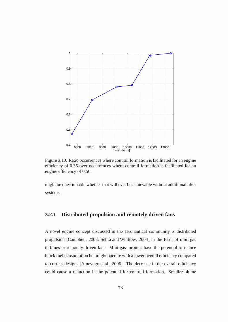
6000 7000 8000 9000 10000 11000 12000 130000.4
0.5
0.6
0.7
0.8
0.9
1
altitude [m]
Figure 3.10: Ratio occurrences where contrail formation isfacilitated for an engineefficiency of 0.35 over occurrences where contrail formation is facilitated for anengine efficiency of 0.56
might be questionable whether that will ever be achievable without additional filter
systems.
3.2.1 Distributed propulsion and remotely driven fans
A novel engine concept discussed in the aeronautical community is distributed
propulsion [Campbell, 2003, Sehra and Whitlow, 2004] in theform of mini-gas
turbines or remotely driven fans. Mini-gas turbines have the potential to reduce
block fuel consumption but might operate with a lower overall efficiency compared
to current designs [Ameyugo et al., 2006]. The decrease in the overall efficiency
could cause a reduction in the potential for contrail formation. Smaller plume
78

diameters might lead to a smaller vertical band of the contrail thus reducing the
chance for contrail cirrus formation. A distributed exhaust along the lifting body
could possibly also have an effect on the jet entrainment. The effects of distributed
propulsion on contrail formation would have to be studied ifthis propulsion method
became a serious alternative to common engine practice.
Distributed propulsion in the form of remotely driven fans could be a disadvan-
tage in terms of contrail formation. If the core of the propulsion device is a gas
turbine producing power to drive the fans, the jet of the fansand the exhaust of
the core would be physically separated. This would have an impact on the humid-
ity/temperature ratio distribution in the plume. For common turbofans, the engine
exit conditions in terms of temperature and humidity as considered in the Apple-
man theory for contrail formation are a weighted average of both engine core and
bypass. If both are separated from each other, it could be assumed that both jets
mix independently from each other with ambient air. In figure, 3.11, the mixing
lines for core and fan are separately shown, together with the mixing line assuming
both streams mixing prior to mixing with ambient air. The core exhaust, contain-
ing the entire combustion water and hence being extremely humid, would facilitate
contrail formation even at very warm temperatures. The bypass air, containing no
additional water, would not contribute to contrail formation.
3.2.2 A clean exhaust engine concept
Since the introduction of jet engines for commercial air traffic, there has been
steady improvement in their fuel economy. Whilst the reasonfor better fuel econ-
omy of early aircraft was to extend the accessibility to air travel for a larger fraction
of population, environmental aspects have become the main reason for cleaner tech-
nologies. First jet engines suffered from poor component efficiencies, restricted
79

Figure 3.11: The effect of remotely driven fans on contrail formation.
turbine inlet temperatures, low achievable pressure ratios and low thrust to weight
ratios. The advent of advanced combustor technology, higher component efficien-
cies, new materials, blade cooling techniques, higher pressure ratios thanks to multi
spool arrangements and large bypass ratios improved the engine performance. Fu-
ture developments considering current engine architecture have the potential for
further improvements. However, they are incremental, takeplace on a subsystem
level and are associated with increasing technological andfinancial investments.
Maclin and Haubert [2003], Sehra and Whitlow [2004] and Seidel et al. [2001] state
that only revolutionary changes in engine design can lead tothe significant ad-
vances in engine fuel economy and environmental compability required in the light
of the annual growth rates in air traffic. Although approaches utilising fuel cells and
similar mechanisms may be feasible [Alexander et al., 2002], they require signifi-
cant deviation from current gas turbine practice. Hence it would be more desirable
80

to provide a revolutionary solution with respect to existing gas turbine technology
that can also operate with any available hydro or hydrocarbon based fuel. In this
section, an engine concept is presented that, apart from suppressing contrails, has
also the potential for lower emissions. The following requirements were set on
a novel engine architecture: higher thermal efficiency, anda reduction in water
vapour, soot and aerosol emissions to avoid the formation ofcontrails and cirrus
clouds, and lower NOx emissions. Generally, the formation of contrails could be
avoided by reducing the water content in the exhaust gases ofa jet engine. A tem-
perature drop of the exhaust gases would be necessary to facilitate water conden-
sation inside the engine, which could be achieved with heat exchangers. The water
condensate could be stored either on board the aircraft or released into the atmo-
sphere in the solid or liquid state for precipitation. The clean exhaust engine con-
cept, patented in Noppel et al. [2007], is a derivative of thestandard intercooled and
recuperated engine cycle with a condensation stage. The intercooled-recuperated
engine cycle, which is shown in figure 3.12(b), enables a substantial improvement
in thermodynamic work potential, ultimately leading to lower fuel consumption
[Boggia and Rud, 2005]. A reduction in NOx is possible through the reduction in
fuel flow and lower pressures inside the engine, yielding lower levels of NOx for-
mation during combustion. The intercooler is a heat exchanger, typically placed
between the low pressure compressor LPC and high pressure compressor HPC.
The flow on the cold side of the heat exchanger is usually bypass air. Intercool-
ing reduces the work required for the compression of the air in the HPC. The hot
gases leaving the LPT are used to heat the pre-combustor air in the recuperator, so
more heat is used to generate useful work. In this arrangement, the thermal effi-
ciency does not increase for higher pressure ratios, but is maximum for a specific
pressure ratio. The overall effect can be a significant improvement compared to
conventional gas turbine cycles at lower OPR and TET.
81

LPC HPC CC HPT LPT
REC
DHU
IC
I
I
O
O
(a) Novel concept based on a intercooled recuperated enginecycle.
LPC HPC CC HPT LPT
RECIC
I
O OI
(b) Intercooled recuperated engine cycle.
Figure 3.12: Novel engine concept vs. intercooled recuperated engine cycle.
Contrails form in the exhaust plume of an aircraft if the ratio of water partial pres-
sure to temperature in the exhaust, denoted by the slope of the mixing lineσ, is
below a certain value. Equation 2.3 assumes that all water emerging during com-
bustion is contained in the engine exhaust. The ratio could be artificially lowered
by removing the water from the exhaust inside the engine. This could be achieved
if the temperature after the LPT is reduced so water condenses within the engine.
A temperature reduction down to some 10 K above ambient temperature would be
required to facilitate water condensation inside the engine. However, reducing the
flow of the exhaust by simply transferring heat energy outside the engine without
utilising it would cause a reduction is engine efficiency.
An intercooled and recuperated cycle in a novel arrangementexhibits the poten-
82

tial for water condensation within the engine without compromising engine effi-
ciency. The recuperator redirect heat energy into the engine core flow, where it is
not wasted. The temperature of the flow exiting the recuperator, already cooled to
a certain degree, is further reduced by applying an additional heat exchanger. In
the following, the additional heat exchanger is referred toas condensation stage. It
operates with bypass or ambient air on the cold side. For sufficiently low tempera-
tures, this will cause condensation of the water contained in the exhaust within the
engine. The dry and cold air leaving the condensation stage contain less water, but
what is required for contrail avoidance is a dry and relatively hot exhaust. Thus,
the flow exiting the condensation stage is used in the intercooler to chill the flow
between the compression stages. This has the effect of increasing the exhaust tem-
perature, further reducing the potential for contrail formation and increasing the
engine efficiency simultaneously. A gas path diagram of the clean exhaust engine
concept is given in figure 3.12(a). The major differences between the clean exhaust
engine concept and the conventional intercooled recuperated cycle is that the clean
exhaust engine concept has an additional heat exchanger, the dehumidifier, and that
the intercooler operates with core air only.
Figure 3.13 shows the water partial pressure on a phase diagram of water for differ-
ent stations within the engine and in the exhaust plume. Static flow temperatures
and pressures are considered for the stations within the engine, whereas stagna-
tion properties relative to the atmosphere frame of reference are considered in the
plume. Mixing is assumed to take place adiabatically and isobarically. The water
saturation pressure is calculated considering clean watercondensing on a flat sur-
face [Flatau et al., 1992]. The flow exiting the LPT, being relatively hot and humid,
is cooled by about 400K. The decrease in water partial pressure in the recuperator
occurs due to the pressure loss within the heat exchanger as adecrease in absolute
pressure does also imply a decrease in the partial pressuresof the flow constituents.
83

Figure 3.13: Engine stations on a phase diagram of water.
At the condensation stage exit, the flow has a temperature lowenough for water to
exist in the liquid state. Assuming condensation of water, the partial pressure at
the condensation stage exit is then determined by the liquidsaturation pressure at
the prevailing temperature. The exhaust gas temperature increases again in the in-
tercooler. Again, the drop in partial pressure is caused by the overall pressure loss
in the heat exchanger. The temperature of the exhaust gases exiting the cold side
of the condensation stage and the cold side of the intercooler was calculated to be
the flow stagnation temperature relative to the atmosphere frame of reference. The
exhaust flow from the cold side of the intercooler contains noadditional water. The
84

mixing of the two flows can take place inside the engine or in the plume. In this
study, it was assumed that the mixing takes place outside theengine and it was
assumed that they mix prior to the mixing with ambient air. The actual mixing
line in figure 3.13 represents the mixing of the mixed exhausts with ambient air.
Furthermore, the critical mixing line is shown, which is indicating whether contrail
formation is facilitated or not. It is a tangent to the water saturation pressure line
originating from the ambient state of the atmosphere. If theactual mixing line is
below the critical mixing line, the formation of contrails is not facilitated, because
contrails form only if the actual mixing line surpasses the region for which water
is present in the liquid phase in a phase diagram as mentionedin previous sections.
Additionally, the theoretical mixing line is shown. It represents the mixing line of
the mixed exhausts with ambient air if no dehumidification took place. The actual
mixing line and the theoretical mixing line would coincide if no dehumidification
occurred within the engine.
The condensation of water can be expected to occur on the walls of the heat ex-
changer, but also on the particles that are contained in the exhaust. This would
result in the scavenging of particles and aerosols from the exhaust, leaving the en-
gine exhaust free from particles and aerosols. The condensed water, present in the
liquid state, could be partially redirected into the combustion chamber. An 80% re-
duction in NOx emissions is possible injecting water into the combustor asshown in
figure 3.14 [Lefebvre, 1983]. Water injection during takeoff and climb conditions
has been successfully demonstrated in the lab by Daggett et al. [2004]. With this
engine concept, NOx reduction would become feasible during the entire journey.
85

Figure 3.14: NOx reduction through water injection [adopted from Lefebvre,1983].
Cycle optimisation
A set of optimisations was performed to calculate the cycle performance. There-
fore, a mathematical representation of the cycle was developed as part of an MSc
project by Lucisano [2007]. The performance model was linked to a contrail fore-
cast model. Phoenix Model Center, a commercially availablegenetic optimisation
algorithm computer programme, was used to calculate the combination of design
parameters that yield in maximum engine efficiency. The design variables were
overall pressure ratio, fan pressure ratio, bypass ratio and the ratio of the high pres-
sure compressor ratio to the low pressure compressor ratio.
Three sets of optimisations were carried out considering a range of turbine en-
try temperatures between 1600K and 2200K. In the first set, the objective of the
optimisation was to calculate the most efficient cycle regardless of its ability to
86

suppress contrails. In subsequent runs, the objective was to calculate the most effi-
cient cycle that would allow the suppression of contrails. As it was discovered that
the optimum cycle performance also depends on the ambient ice-supersaturation, 2
different levels of ambient ice-supersaturation were taken into account: 115% and
130%. Ambient conditions where held at 33,000 feet (10,058 metres) and Mach
0.8 during all optimisations. Component efficiencies represented latest technology
levels. The heat exchanger effectiveness’ of the intercooler and recuperator were
assumed to be 0.90, and 0.95 for the condensation stage, as relatively low tem-
peratures close to ambient are required to facilitate watercondensation inside the
engine.
Optimisation results are given in figures 3.15 to 3.19. In general, cycles with higher
TET result in better specific fuel consumption. For a given TET, it was calculated
that the specific fuel consumption is higher for cycles wherecontrail suppression is
considered than for the baseline cycle where contrail suppression was not taken into
account during the optimisation process, whereas the higher the levels of ambient
ice-supersaturation cause larger drawbacks in terms of specific fuel consumption.
In terms of overall engine efficiency, as shown in figure 3.16,the cycles were all
between 0.44 and 0.52, which is well above what is achieved with current engines
and close to what is theoretically available with conventional technology (see sec-
tion 3.2 on page 75). Higher component efficiencies, lower pressure losses in the
heat exchangers or higher TET yield overall engine efficiencies above what is pos-
sible with conventional engine architecture. According tothe results, the optimum
overall pressure ratio is increasing with TET as shown in figure 3.17. It is lowest
where contrail avoidance is not considered during optimisation and is increasing for
higher levels of ambient ice-supersaturation. The optimumbypass ratio shown in
figure 3.18, is increasing with TET. No significant influence of ice-supersaturation
on optimum bypass ratio was found. However, the results suggest that this engine
87

10.4
10.6
10.8
11.0
11.2
11.4
11.6
11.8
12.0
12.2
12.4
69 70 71 72 73 74 75 76 77 78 79
Specific Thrust [N/kg/s]
SF
C [
(g/s
)/kN
]
contr. not cons.
ISS=115%
ISS=130%1700K
1600K
1800K
1900K
2000K
2100K
2200K
1700K
1600K
1800K
1900K
2000K
2100K
2200K
1700K
1600K
1800K
1900K
2000K
2100K
2200K
Figure 3.15: SFC vs. specific thrust.
concept requires very high bypass ratios to be efficient, exceeding what is common
with conventional turbofan configurations, which is about 10 for modern engines.
Hence, this engine concept would be more suited for propulsors where the bypass
ratio can be designed to be very large, such as unducted fans or remotely driven
fans. The optimum fan pressure ratios are shown in figure 3.19, indicating fan
pressure ratios around 1.30, which is below that of current conventional engines
and what can be achieved with unducted fans. For the case thatcontrail avoidance
is not considered during optimisation, the optimum fan pressure ratio is not affected
by the TET. In the other cases, the optimum fan pressure ratiois increasing with
TET and is lower for higher levels of ice-supersaturation.
In general, heat exchanger size is predominantly dependenton the mass flow, heat
exchanger effectiveness and the desired temperature change. The cycles respond
88

overall engine efficiency vs TET
44%
45%
46%
47%
48%
49%
50%
51%
52%
1600 1700 1800 1900 2000 2100 2200
TET [K]
ov
era
ll e
ng
ine
eff
icie
nc
y
contrails
ISS=115%
ISS=130%
Figure 3.16:η vs. TET.
OPR vs TET
10
15
20
25
30
35
40
1600 1700 1800 1900 2000 2100 2200
TET [K]
OP
R
contrails
ISS=115%
ISS=130%
Figure 3.17: OPR vs. TET.
89

BPR vs TET
20
22
24
26
28
30
32
34
36
38
40
1600 1700 1800 1900 2000 2100 2200
TET [K]
BP
R
contrails
ISS=115%
ISS=130%
Figure 3.18: BPR vs. TET.
FPR vs TET
1.27
1.28
1.29
1.30
1.31
1.32
1.33
1600 1700 1800 1900 2000 2100 2200
TET [K]
FP
R
contrails
ISS=115%
ISS=130%
Figure 3.19: FPR vs. TET.
90

with an increase in the overall temperature change to a decrease in heat exchanger
effectiveness’, potentially causing the heat exchanger tobe even larger. A relatively
high effectiveness in the condensation stage is crucial in order to achieve a low
temperature within the engine that facilitates water condensation. This temperature
is within the ambient temperature range, so the temperaturedifference between the
flows that exit the condensation stage at the core side and enter at the bypass side
is relatively small, requiring a relatively high heat exchanger effectiveness.
Hence, it can be concluded that advanced heat exchanger technology in terms of ef-
fectiveness, weight, and pressure loss is essential for thefeasibility of this concept.
Super conducting heat transfer material is being investigated and similar materials
could be available in the future [Qu, 2000]. Because the required temperature in
the condensation stage is determined by the temperature at which water conden-
sation occurs, a reduction in water saturation pressure would cause a reduction in
the required temperature difference. A reduction in the water saturation pressure
required for condensation could be achieved by applying curved surfaces within
the heat exchanger (Kelvin effect) or advanced materials with very good hydration
behaviour.
3.3 Aircraft technology
This section deals with methods for contrail avoidance through modifications in the
airframe.
91

3.3.1 Aircraft optimisation
In general, aircraft are designed to serve a particular market and to maximise the
earning capacity for the manufacturer. Factors driving theaircraft design are such
as payload, range, the prevailing air-traffic infrastructure, and the aircraft’s compet-
itive advantage in terms of economical performance. The design process typically
yields a configuration that meets the design requirements within the constraints
imposed by regulations regarding safety, performance, andenvironmental impact.
As in particular the environmental impact of contrails is increasingly emphasized,
regulations might be introduced with the objective of contrail mitigation. These
regulations will either affect the current aircraft fleet, e.g. how aircraft are oper-
ated, or influence the design of next generation aircraft. Airlines would have to
deal with the former approach, whereas the manufacturer would have to respond to
the latter as it might cause a shift of the design requirements.
Fichter et al. [2003] concluded that contrail formation could be mitigated if air-
traffic took place at lower altitudes on a global scale. As discussed in previous
section, both fuel consumption and contrail formation of a particular aircraft are de-
pendent on cruise altitude, and the shift of the air-traffic corridors would come with
a fuel burn penalty. The fuel burn penalty could be reduced optimising the aircraft
for altitudes where contrail formation could be mitigated,and once decided how
to position an aircraft in the market in terms of payload, range and cruise speed,
its optimisation in terms of cruise altitude could yield an acceptable compromise
between fuel burn and contrail formation. An approach dealing with the aircraft op-
timisation for minimal environmental impact is given in Antoine and Kroo [2004].
However, contrails were not taken into account in that study, and aircraft optimisa-
tion in a more global context is given in the following, describing how the design
processes could be adapted to meet new design requirements regarding contrail
92

formation. Therefore, a methodology was developed that considers contrail for-
mation during the aircraft design process, which was applied for the optimisation
of the baseline aircraft configuration. The methodology canbe broken down into
two parts. One part predicts the performance of the aircraftconfiguration, which
depends on design variables, technology parameters, and mission requirements.
The aircraft performance can be optimised varying the design variables. Combin-
ing the calculated performance with air-traffic data, the fuel consumption can be
calculated on a global scale. The second part includes the calculation of the envi-
ronmental impact from contrails. As the calculation of the radiative forcing from
contrails is not straightforward, this study considers theamount of contrails formed
only. It is measured in contrail-km, which is the cumulativesum of the fractions
of flight paths where the formation of contrails is facilitated on a global scale. This
is facilitated by combining air-traffic data with historical meteorological data. A
representation of the overall procedure is given in figure 3.20.
NASA’s Flight Optimisation System (FLOPS) was used for performance calcula-
tion and multidisciplinary optimisation of a particular engine and aircraft configu-
ration. The code computes airframe weight, airframe aerodynamics, engine weight
and engine performance according to the airframe and enginerelated parameters
and design variables, from which the block fuel is calculated. The part covered by
FLOPS is framed with a dashed line in figure 3.20.
Ideally, optimisation of the aircraft configuration is carried out considering contrail
formation already during the optimisation process. The figures of merit, block fuel
and contrails, would then be combined in the objective function, represented by the
dashed arrow in figure 3.20. In this study, the aircraft was optimised for minimum
block fuel, and the resulting configuration was then subsequently assessed in terms
of contrail formation. This would allow a comparison between different config-
urations regarding fuel consumption and contrail formation. The aircraft design
93

Constraints Design variablesParametersMission
Performance and weight calculation
Block fuel
Optimised configuration
Optimiser
routine
Off-design performance
routine
Air-traffic density
routine
Contrail coverCarbon emissions
routine
Air traffic raw dataroutine
Flight mission distribution
Meteorological dataroutine
Minimum required efficiency
Optimiser
FLOPS
Figure 3.20: Layout of aircraft design process where contrail formation is takeninto account.
variables were wing area, thickness to chord ratio and sweepangle; engine design
variables were bypass ratio and take-off thrust.
The design point mission was defined by range, cruise speed interms of true air
speed, and initial cruise altitude. Block fuel is calculated considering continuous
climb during cruise. Defining a minimum and maximum cruise altitude, the aircraft
is enforced to not fly within a certain altitude band for both design point and off-
design point missions. Mission requirements in terms of landing and take off field
length, minimum rate of climb during initial climb (one engine off) and approach
speed were taken into account according to the FAA regulations. During cruise, the
engine is allowed to operate with at most 90% throttle setting. These requirements
were considered as constraints and accommodated in the objective function, im-
94

taxi takeoffout
initialclimb
acceleration
climb
cruise
continuousclimb
cruise
descent
landing taxi
field length field length
rate of climbpotential rate of climb
in
Figure 3.21: Mission definition and constraints.
pacting the airframe and engine design optimisation. Figure 3.21 shows a typical
flight mission as applied in FLOPS. Constraints are indicated in italic letters.
Air-traffic density, defined as the sum of distances flown by aircraft within a certain
volume over a given time period, was calculated from a database provided by Cran-
field University’s Department of Air Transport. The database holds information of
national and international scheduled commercial flights. Knowing departure, des-
tination, departure time and flight duration of each scheduled flight, the air-traffic
density could be calculated assuming the flights to follow great circles. Calculat-
ing the intersections of the flight path with the map grid, it could be dissected into
several fractions∆S, as shown in figure 3.22. The areasA, known as spherical
quadrangles, are defined by the intersecting grid lines. Theratio of the fractions of
the flight path∆Sand the areasA yield the air-traffic density∆S/A. The air-traffic
density resulting from several flights can be calculated by taking the sum of the
air-traffic densities resulting from the individual flights.
Only the flights that would be undertaken by the considered aircraft class are of
interest when calculating air-traffic density and fuel burnon a global scale. An
extensive market research would be necessary to make an accurate assumption re-
garding the routes on which the aircraft is going to operate.In this study, it was
95

A����������
S∆
destination
latit
ude
longitude
departure
Figure 3.22: Schematic of calculation of air-traffic density.
assumed that the aircraft would operate on routes that are contained in the database
with between 200 and 250 passengers and a maximum range of 8000nm. The re-
sulting distribution of journey length of flights with aircraft between 200-250 seats
is given in figure 3.25.
As the optimisation of the aircraft was carried out considering the journey to take
place within a certain altitude band, it was necessary to calculate the air-traffic
density in three dimensions. Therefore, the initial cruisealtitude, the final cruise
altitude, and the fractions of the journey for climb and descent were calculated us-
ing the off design capabilities of FLOPS and stored in the form of response surfaces
for each altitude scenario. Also, the diurnal variability in air traffic was taken into
account when the air-traffic density was calculated. Knowing departure time and
destination time for each flight, sections of the flight pathscould be attributed to
different times. Four air-traffic density maps were computed for each altitude sce-
nario, covering the time periods 0-6h, 6-12h, 12-18h, and 18-24h (Universal Time).
The resulting maps, as shown in figure 3.23, are the sum of the air-traffic density
96

Figure 3.23: The cumulative air traffic density over all altitudes in km/(km2 hour)considering 200-250 seater only. 00-06h (top left), 06-12h(bottom left), 12-18h(top right), 18-24h (bottom right)
of all altitude levels.
Regions that facilitate the formation of contrails are determined by local ice-super-
saturation, altitude, ambient temperature and engine efficiency. The operational
weather analysis data from the MetOffice unified model of the year 2005 as de-
scribed in the appendix on page 157 was evaluated regarding contrail formation
applying the Appleman criterion. As the engine efficiency isan aircraft related
parameter in the Appleman criterion, the minimum engine efficiency required for
97

Figure 3.24: Critical mixing line slope as function of ice-supersaturation and tem-perature.
contrail formation was calculated in the first instance for each time interval of the
MetOffice data. In order to speed up the calculation, a look-up table was com-
puted of the critical mixing line slopeσ depending on ambient temperature and
ice-supersaturation. This would make the time consuming iteration of equation 2.3
redundant. Figure 3.24 is based on the look-up table and shows the isolines for the
critical mixing line slope on a temperature-ice-supersaturation chart.
In the second instance, the amount of contrails formed was calculated in terms of
contrail-km for each time interval for each altitude scenario combining air-traffic
density data and the data containing minimum required engine efficiency for con-
trail formation. As aircraft optimised for different altitudes cruise with different
98

overall efficiencies, the calculation of contrail occurrences was carried out with
different overall engine efficiency for each altitude scenario.
The aircraft type considered in this study was based on the baseline aircraft as de-
scribed in the appendix on page 157. Altitude scenarios werechosen to be in 1,000
feet (305m) steps with 34000 feet (10.36km) as baseline. Best estimates for future
engine and aircraft related parameters were made accessible by industry and could
be derived from information available in the public domain.Airframe technology
related parameters, determining primarily material weight and aerodynamic wing
performance, and engine related technology parameters such as maximum turbine
entry temperature, overall pressure ratio, fan pressure ratio or parameters related to
the mechanical integrity of the turbomachinery, were held constant for all altitude
scenarios.
The differences in block fuel consumption compared to the baseline configuration
was calculated for both the design mission and on a global scale. The resulting dis-
tribution of journey length of flights with aircraft between200-250 seats is given in
figure 3.25. Most of the flights occur for legs less than 3000nm. The database holds
virtually no entries for flights above 6250nm. This is because there is currently no
aircraft with 200-250 seats that can serve this range. Aircraft with 200-250 seats
and a maximum a range of 8000nm would serve an emerging marketof long haul
services away from hub-to-hub towards point-to-point.
Figure 3.26 shows the change in fuel consumption relative tothe baseline configu-
ration. The block fuel consumption ultimately increases asthe aircraft is designed
to fly at both lower or higher altitudes. According to the results, an aircraft of the
considered class optimised for 31,000 feet would consume 2.4% more fuel at its
design point than an aircraft optimised for 34,000feet. On aglobal scale, the fuel
burn penalty would be 1.0%. The difference in fuel burn for aircraft designed for
99

500 1000 1500 2000 2500 3000 3500 4000 4500 5000 5500 6000 6500 7000 7500 80000
1
2
3
4
5
6
7
8
9
10
journey length [nm]
dist
ribut
ion
[%]
Figure 3.25: Journey length distribution for aircraft with200-250 seats.
37,000feet is calculated to be 4.8% at the design point, and 5% on a global scale.
Figure 3.27 shows the relative change in the design variables for the different al-
titude scenarios. Thrust and bypass ratios are calculated at sea level static. The
results suggest that aircraft optimised for higher altitudes have higher thrust re-
quirements, larger wing areas, but smaller bypass ratios. The effect is not inversed
for aircraft optimised for lower altitudes. The results suggest that the optimum by-
pass ratio is increasing for aircraft designed for lower altitudes, thrust requirements
would be lower and the wing area would also be larger.
The aircraft configuration resulting from an optimisation is dependent on various
factors. It is, however, mainly affected by the change in airdensity at higher al-
100

-2%-1%0%1%2%3%4%5%6%7%8%9%
-5k -4k -3k -2k -1k base +1k +2k +3k
altitude [feet]
ch
an
ge in
fu
el b
urn
Figure 3.26: Fuel burn penalty relative to baseline configuration (34,000feet).
titudes, impacting lift, drag and engine performance. Additionally, design con-
straints impact the final design of aircraft. The fuel consumption and hence aircraft
weight depends primarily on the thrust requirement during cruise and the engine ef-
ficiency. At high altitudes, where the air density is lower, larger wings are needed to
obtain enough lift, impacting aircraft weight and drag. At the same time, the mass
flow through the engine needs to be increased in order to obtain enough thrust.
An ever increasing engine diameter can, however, not be accommodated due to
limited space below the pylon, engine weight and increasingnacelle drag. Hence,
the engine exit velocity is increased to provide enough thrust, which is achieved
through a lower bypass ratio. This, in effect, negatively affects the overall aircraft
efficiency. As a result of increasing wing area and decreasing engine efficiency at
higher altitudes, the block fuel consumption is increasing.
Aircraft optimised for lower altitudes can be designed withlarger bypass ratios,
allowing better overall engine efficiencies. This is because the higher air density at
101

Figure 3.27: Relative change in design variables relative to baseline (34,000feet).
lower altitudes allows sufficiently large air mass flows through the engine without
increasing its diameter. At low altitudes, however, the higher air density causes
an increase of the parasitic drag, impacting fuel consumption. Minimum climb
requirements for one engine off conditions at 1500 feet altitude also result in larger
wing areas, having an increasing effect on block fuel consumption.
The overall relative change in contrail formation for each altitude scenario on a
global scale, measured in terms of contrail-km, is given in figure 3.28. Aircraft
of the considered class optimised for lower altitudes tend to cause more contrails,
whereas higher cruise altitudes indicate a decrease in contrail formation. According
to the results, almost 58.0% more contrails would form if theaircraft was designed
for 31,000 feet instead of 34,000 deet, but 10.1% fewer contrails would form if the
aircraft was designed for 37,000feet.
The persistence of contrails, and ability to spread to contrail cirrus, is primarily
102

-20%
-10%
0%
10%
20%
30%
40%
50%
60%
-3k -2k -1k base +1k +2k +3k
altitude [feet]
ch
an
ge in
co
ntr
ail-k
m
Figure 3.28: Change in contrail formation relative to baseline configuration (34,000feet).
dependent on ambient ice supersaturation. Therefore, the increase in contrail for-
mation for different levels of ice-supersaturation was calculated: results are shown
in figure 3.29. Configurations optimised for lower altitudeswould particularly in-
crease contrail formation under relatively high ice-supersaturated conditions.
The results suggest that aircraft of the considered aircraft class designed for lower
altitudes would produce more contrails and would ultimately consume more fuel.
If designed for higher altitudes, the fuel burn would also behigher but fewer con-
trails would be produced. This is in contradiction with Fichter et al. [2005], where
results suggest that cruising at lower altitudes would reduce contrail occurrences
(see section 3.6 on page 68). The difference is that in this study only one particular
aircraft class and its associated contrail occurrences areconsidered. There is an
altitude at which contrails are most likely to form, and aircraft can either cruise
above or below it. As the optimum cruise altitude in terms of fuel consumption
103

-50%
0%
50%
100%
150%
200%
250%
300%
100 110 120 130 140 150
ice-supersaturation [%]
ch
an
ge
re
lati
ve
to
ba
se
-3k
-2k
-1k
+1k
+3k
Figure 3.29: Change in contrail formation relative to baseline configuration (34,000feet) for different levels of ice- supersaturation (altitude variation in feet).
is dependent on various parameters such as payload, cruise speed and technology,
individual optimisation of aircraft for minimum contrail avoidance would shift the
air-traffic towards altitudes where contrail formation is mitigated. This would not
necessarily imply that all aircraft would be designed for lower altitudes. If contrail
formation is most likely to occur for a particular altitude,then contrails could be
avoided by designing aircraft for both higher or lower cruise altitudes, depending
on the design requirements and the technology. It has to be taken into account,
however, that contrails and carbon dioxide are not the only pollutants from air traf-
fic. The environmental impact of other emissions, such as NOx, varies with altitude
and would have to be taken into account for a more integrated analysis.
Further reducing cruise altitude of this aircraft class would probably make sense in
terms of contrail formation, because for much lower altitudes, contrail occurrences
would diminish again. However, the fuel burn penalty would be over proportionally
104

larger. New technologies, such as propfans or compromises in terms of aircraft
speed, could alleviate the fuel burn penalty. A study in the form of an MSc project
as part of this work programme was carried out by Faupin [2006], comparing the
performance of unducted fans and turbofans on medium haul routes. Fuel savings
utilizing unducted fans relative to the turbofan configuration are given in figure
3.30. If aircraft were designed to operate at lower cruise altitudes, the switch to
unducted fans seems to be promising. According to the results, the unducted fan
configuration consumes between 10% and up to 22% less fuel at lower altitudes
relative to the turbofan configuraiton, depending on the design cruise Mach number.
Hence, unducted fans could be a way to reduce both fuel consumption and contrail
occurrences at the same time.
3.3.2 Airframe and engine integration
Aircraft geometry has an effect on the vortex structure and intensity. The relative
position of the jet exhaust to the vortices determines its entrainment. The for-
mation, evolution and radiative properties of a contrail are affected in two ways
[Lewellen and Lewellen, 2001]: a) a more effective jet entrainment causes ice par-
ticle evaporation due to vortex descent and the associated adiabatic heating and b)
less effective jet entrainment prevents vertical spreading of the contrail, reducing
the chance for contrail cirrus formation and leading to lesseffective mixing of the
exhaust gas with the ambient air.
Configurations with a larger gap between exhaust and wing tipvortices (e.g. fuse-
lage mounted engines) might reduce the probability of contrail dispersion and thus
contrail cirrus. A more effective jet entrainment could be achieved by placing the
jet closer to the vortices.
105

Figure 3.30: Fuel savings of unducted fan relative to turbofan configuration[adopted from Faupin, 2006].
Some novel airframe concepts often discussed in the aeronautical community are
the blended wing body and the joined wing aircraft. Both concepts potentially
affect the vortex pattern and strength, which might have an effect on contrail for-
mation and persistence. In Gierens and Strom [1998], it is concluded that the for-
mation of aerodynamic contrails is possibly more likely to occur for heavy, slow,
wide-body aircraft.
106

Kerosene LH2 Methane0.029 kg/MJ 0.075 kg/MJ 0.045 kg/MJ
Table 3.3: Energy specific emission index for different fuels [adopted fromPenner et al., 1999; table 7-11].
3.4 Fuels
Potentially alternative fuels for aviation are other carbon based fuels such as ethanol
or methanol. Hydrogen is also often discussed in the aeronautical community as
fuel for next generation aircraft. In the following, these fuels are discussed in the
context of contrail avoidance.
According to equation 2.2, fuels with higher water emissions indices would in-
crease the potential for contrail formation. However, the fuel calorific valueqnet,
appearing in the denominator in equation 2.2, is also fuel specific and contrail
avoidance is affected by both parameters. The ratioEI/qnet, called the energy-
specific emission index, combines both fuel specific parameters in equation 2.2.
Lower values ofEI/qnet imply lower values of the mixing line slopeσ, and would
hence reduce the potential for contrail formation. The values for hydrogen and
methane are compared to kerosene in table 3.3. Both hydrogenand methane have
higher values ofEI/qnet and would hence increase the potential for contrail forma-
tion.
Hydrogen, which is generally seen as the most likely alternative to kerosene as
aviation fuel, does not cause the formation of soot or aerosol particles during com-
bustion, having an impact on the radiative properties of contrails. This additional
effect has been investigated in several studies and is discussed in more detail in
section 3.4.3 on page 109.
107
3.4.1 Fuel sulphur content
Sulphur plays an integral role in the contrail formation process, facilitating water
nucleation on soot particles and providing volatile particles serving as condensation
nuclei. A reduction of the fuel sulphur content would reducethe emission of SO3
and H2SO4, and have an impact on the aerosol density in the plume and contrail
precursor activation. It would be technically possible to reduce the fuel sulphur
content. However, reducing the fuel content might have no oronly a very little
impact on contrail formation as mentioned in section 2.1.2.Water nucleation on
soot particles is believed to be independent of the presenceof sulphur species in
the plume [Popovitcheva et al., 2001]. And even if sulphur free fuel led to the
absence of volatile particles and avoided water nucleationon soot particles, ambient
background particles would still provide sufficient condensation nuclei. Contrails
formed on background particles, however, would very likelybe composed of fewer
but larger ice particles, which because of their radiative properties could result in
a lower positive radiative forcing. The impact of contrailswith fewer but larger
particles on contrail cirrus formation has not been investigated up to now.
3.4.2 Fuel additives
Gierens [2007] explored the possibility of using fuel additives for contrail avoid-
ance. It was concluded, however, that they would not be a viable contrail miti-
gation option. Fuel additives, if used to change hygroscopic properties of black
carbon particles and hence suppress water condensation, would very likely cause
the formation of contrails with fewer but larger particles,possibly having an impact
on the radiative properties of contrails. Fewer but larger particles could potentially
decrease the radiative forcing of contrails. The presence of volatile particles, how-
108

ever, would still facilitate water condensation, possiblyoffsetting the advantages of
using fuel additives.
3.4.3 Hydrogen
The switch to hydrogen-fueled aircraft is being widely discussed in the aeronauti-
cal community as their emissions are restricted to water andoxides of nitrogen only
[Ponater et al., 2006]. However, as discussed on page 107, the higher energy spe-
cific emission index of hydrogen powered aircraft would increase the potential for
contrail formation as a higher water emission index has an increasing effect on the
mixing line slope. The significance can be seen in figure 3.31,where the minimum
engine efficiency required for contrail formation for a kerosene and a hydrogen
powered aircraft is shown on ice-supersaturation-altitude diagrams. The diagrams
are based on the ISA standard atmosphere and do not consider temperature devia-
tions from standard values. Considering current engines, typically operating with
an efficiency of about 0.35, contrail formation would thermodynamically always be
facilitated at altitudes above 7250 metres if hydrogen was used as fuel. Kerosene
powered aircraft of the same efficiency would facilitate contrail formation only at
altitudes above about 9250 metres. At lower altitudes, the air might be too warm to
facilitate the formation of contrails from kerosene-fueled aircraft but not the forma-
tion of contrails from hydrogen-fueled aircraft. At higheraltitudes, the switch to
hydrogen-fueled aircraft would not have a significant effect on contrail formation
[Marquart et al., 2001].
Studies suggest that the global annual mean contrail cover from hydrogen fueled
aircraft would increase by a factor of 1.56 compared to kerosene-fueled aircraft.
However, young contrails from hydrogen-fueled aircraft would probably consist of
fewer but larger particles with a very high sensitivity to variations in background
109

(a) hydrogen powered aircraft.
(b) kerosene powered aircraft.
Figure 3.31: Minimum engine efficiency required for contrail formation: keroseneand hydrogen.
110

aerosols [Strom and Gierens, 2002]. This would have an effect on the optical thick-
ness and particle precipitation rate, and hence on the associated radiative forcing of
contrails from hydrogen fueled aircraft. The radiative forcing of contrails caused
by a fleet of hydrogen fueled aircraft could potentially be lower than the radiative
forcing from contrails caused by a kerosene fueled fleet. This is because the micro-
physical properties of contrail particles from hydrogen fueled aircraft differ from
the kerosene equivalents [Marquart et al., 2005].
Alexander et al. [2002] investigate the possibility of using hydrogen in fuel cells
powering electric motors for aircraft propulsion. Although the concept is promis-
ing as it results in the total avoidance of contrails and other combustion products
that would occur with kerosene as fuel, the use of break through technologies such
as proton exchange fuel cells and super-conductive electric motors makes its appli-
cation in civil aviation unlikely in the near future.
3.5 Contrail avoidance devices
Contrail avoidance strategies discussed in the previous sections have dealt with
technologies directly linked to the airframe or engine. However, technology de-
veloped independently could also yield the desired effect.In the following, two
distinct approaches are presented: remotely induced heat in the plume could cause
contrail ice particle evaporation or prevent ice particlesfrom nucleating, and soni-
cation could be used to modify particles size or prevent water condensation of water
on particles. Depending on the energy required for these approaches, they might
be very attractive for contrail avoidance since existing aircraft could be retro-fitted
with such a technology.
111

Figure 3.32: Remotely induced contrail avoidance.
Figure 3.32 shows the idea of remotely induced heat on a waterphase diagram.
A mixing line facilitating contrail formation is represented by the solid line. If
the area in the phase diagram for which water is present in theliquid state could
be avoided, condensation of water would be prevented. This is represented by the
curved dotted line. Alternatively, evaporation of water droplets or ice crystals could
be achieved if heat was induced post condensation, represented by the dashed line.
Both possibilities were patented during the PhD project. They are discussed in the
following in sections 3.5.1 and 3.5.2.
112

3.5.1 Remotely induced evaporation
If the evaporation of water droplets or ice particle in the plume could be achieved,
the formation of contrails could be suppressed. Heat could be remotely induced
by applying electromagnetic radiation. If the frequency ofthe electromagnetic
radiation matches the excitation frequency of water or other constituents of the
exhaust, radiation would be absorbed and converted into heat energy, elevating the
temperature of the contrail ice-particles and eventually causing melting followed
by evaporation or sublimation of the ice particles. Subsequent condensation can be
expected to not reoccur as the liquid phase is required for particle formation. Based
on this hypothesis, remotely induced evaporation is investigated in the following.
Under cruise conditions, temperatures prevail where the heating of water in the
solid state would result in sublimation. Assuming the heating is taking place adi-
abatically and isobarically, the energy required for particle sublimation is deter-
mined by the temperature difference between the saturationpressure temperature
and the particle temperature, and the latent heat of ice. Figure 3.33 shows a phase
diagram of water with the ice-saturation pressure line, anddifferent levels of ice
supersaturation. For given ambient conditions, heating anice particle would re-
sult in an increase of its temperature as indicated in figure 3.33. Further absorbed
heat would cause sublimation from the ice-phase into the gas-phase. Under su-
persaturated conditions, the temperature to achieve saturation is dependent on the
level of ice-supersaturation and ambient temperature. Figure 3.34 shows the tem-
perature difference to achieve saturation temperatures for different levels of ice-
supersaturation. Relatively modest temperature differences, below 5K, would have
to be overcome to achieve saturated levels.
The energy required for ice-particle sublimation is assessed in the following. There-
fore, instant and adiabatic heating is assumed. Rather thancalculating absolute fig-
113

−60 −55 −50 −45 −40 −35 −300
5
10
15
20
25
30
35
40
45
50
T [degC]
Pw
ater
[Pa]
Ice Saturation Pressure120% ISS140% ISS
heat inductionambientcondition
Figure 3.33: Principle for remotely induced ice particle sublimation.
ures, the power consumption for ice-particle sublimation is compared to the engine
power. The net output power of a jet enginePengine is the fraction of the energy
contained in the fuel that is converted into useful work, given by
Pengine= mf uel qnet η0 (3.2)
wheremf uel is the fuel mass flow,qnet is the fuel net calorific value andη0 is the
engine overall efficiency. Assuming the ice crystals would contain water from the
engine only, the power needed to evaporate these ice crystals in the engine plume
114

−60 −55 −50 −45 −40 −35 −301
1.5
2
2.5
3
3.5
4
4.5
5
T [degC]
∆ T
req
uire
d [d
egC
]ISS = 120%ISS = 140%ISS = 160%
Figure 3.34: Temperature difference to saturated conditions.
is the sum of the energy required to achieve saturation plus the latent heat.
Pice = (hlatent+cp, ice ∆T)mwater (3.3)
wherehlatent is the latent heat of ice,cp, ice is the specific heat capacity of ice,
∆T is the required temperature difference and ˙mwater is the water in the plume
considering exhaust water only. With the specific emission index of waterEIwater=
mwater/mf uel, equations 3.2 and 3.3 can be rearranged to
Pice/Pengine=(hlatent+cp, ice ∆T)EIwater
η0 qnet(3.4)
The termPice/Penginedenotes the ratio of the power required for ice particle subli-
mation to engine power.
115

The water emission index and the fuel calorific value of kerosene is about 1.25
and 43MJ/kg, respectively. The specific heat capacity of iceis about 1900J/kg/K
and the latent heat of ice is 334000J/kg. Assuming a temperature difference of 5K
and an engine efficiency of 35%, the theoretical fraction of engine power needed
in order to evaporate contrail ice crystals becomes 2.5%. Considering a device
efficiency of 80%, the power required increases to 3.1%. Since only a fraction of
a journey occurs under conditions where the formation of persistent contrails is
facilitated, the device would be operating only temporarily. For a modern mid-size
commercial passenger aircraft, the block fuel burn penaltyhas been calculated to
be 0.7% assuming the device operating during 10% of the flighttime. The increase
in block fuel is primarily dependent on how long the device isoperating. For
continuous operation of the device, the increase in overallfuel consumption has
been calculated to be as high as 3.6%.
3.5.2 Remotely induced heat to suppress condensation
Alternative to remotely induced heat for ice particle sublimation, the condensation
of water could be suppressed by artificially alevating the temperature of the con-
densation nuclei. Electromagnetic radiation would then beabsorbed by volatile
and non-volatile condensation nuclei. With carbon and sulphur both having a very
high ability to absorb electromagnetic wave radiation, microwaves could be applied
more effectively than in the case of remotely induced evaporation.
As the emissions index of carbon and sulphur species is much lower than for water,
the energy required to prevent water condensation in terms of engine power would
potentially be lower that that required for ice sublimation. With a specific heat
capacity of black carbon of 8.517J/(mol kg) [Lide, 2003] anda molar mass of
12.01g/mol, the mass specific heat capacity is 710J/(kg K), which is below that
116

of ice. The soot emission index is estimated at 0.04E−3kgsoot/kgf uel [Dopelheuer,
1997], well below that of water. The power required in terms of engine power to
heat soot condensation nuclei by 5K can be calculated with formula A.2 setting
the latent heat to zero. Substituting the variables accordingly yields 9.4E−9. This
power requirement would be negligible, equivalent to just several Watts depending
on the engine size. Losses would occur at the microwave device itself and the heat
transfer from the soot particles to the surrounding air. In terms of additional fuel
burn, both the impact from the additional weight and the power consumption could
potentially be as low as fractions of a percent.
3.5.3 Sonication
Sonication, also known as acoustic cavitation, is a processduring which micro size
gas bubbles are created as a consequence of pressure reduction induced through
the application of ultrasound. Applying ultrasound on micrometer sized droplets
can result in their vapourisation. As this technique could be used to prevent the
formation of contrail ice-particles exposing liquid contrail precursors to ultrasound,
it was patented during the PhD project. The energy consumption of ultrasound
devices potentially being relatively low, sonication could be an attractive contrail
avoidance method.
3.5.4 Chemical devices
Although the extent of the environmental implications of contrails is only known
relatively recently, their avoidance has always been of military interest. The visibil-
ity of military aircraft is strongly enhanced in the presence of contrails, and military
117

forces developed interest in their avoidance already in thevery early years of avia-
tion. In the US, a contrail forecast model called JETRAX is operated to allow the
prediction of areas and altitudes that facilitate contrailformation. This enables mil-
itary pilots to avoid regions in the atmosphere that would enhance their visibility
through the formation of contrails. Earlier methods for contrail avoidance included
a simple rear mirror installed in the cockpit to allow pilotsto observe whether a
contrails forms behind the aircraft or not. If so, he would simply climb/descend to
an altitude where no more contrail would form in the aircraftwake.
More sophisticated military contrail avoidance strategies involve the release of
chemicals into the jet exhaust to either suppress contrail formation or cause the
formation of small and invisible contrail particles [Andreson et al., 1970]. With a
possibly negative radiative forcing of contrails consisting of very small particles,
initiating the formation of very small contrail particles could be a solution. The
chemical as described in Andreson et al. [1970] is chlorosulfonic acid (HSO3Cl),
which would break down into hydrogen chloride (HCl) and sulfur trioxide (SO3)
under conditions that can be found in the engine exit and in the plume. Sulfur
trioxide, a deliquescent substance, would take up the waterin the plume, causing
the formation of many small ice particles. According to Andreson et al. [1970],
the mass flow of sulfur trioxide to be injected into the plume is about 1-3% of the
fuel flow. This equates to about 15-43g chloro sulfonic acid required per kg fuel
burned. The device would require a tank with chloro sulfonicacid to be carried
on board the aircraft, implying a fuel burn penalty. Assuming enough substance
carried along to allow operation during 75% of the journey, the additional weight
on a 8000nm flight with a modern mid-size (250 passengers) civil transport aircraft
would be 880-2600kg. The fuel burn penalty for carrying the additional weight
was calculated to be 2.0-6.2% using the NASA flight optimisation system FLOPS.
The substances released with this technology could potentially have a harming ef-
118

fect on the atmosphere. Hydrogen chloride dissolved in water forms hydrochloric
acid, which can be an irritant or even corrosive. With an annual global fuel con-
sumption of 155Mt kerosene in 2002 [Horton, 2006], about 0.5-1.6Mt hydrogen
chloride would have been released into the atmosphere. Comparing this to the an-
nual worldwide industrial production of 20Mt hydrogen chloride per year demon-
strates the dimension, possibly being a strong argument against the application of
chlorosulfonic acid for contrail avoidance in civil aviation.
Alternatively, additions to the plume could be used to alleviate the saturation pres-
sure required for condensation of water [Singh, 1991]. Thiscould be achieved
by injecting detergents or surfactants, such as alcohols, into the plume. The sub-
stances would require to be resistant to oxidation in a relatively hot environment,
and preferably biodegradable. According to Singh [1991], actual tests were per-
formed where the detergent mass flow used to suppress contrail formation was
about 12% of the engine fuel mass flow. Using FLOPS, it was calculated that the
associated fuel burn penalty on a long-haul trip would be in the 17% range, assum-
ing a modern mid-size civil transport aircraft. Laboratorytest results ranging from
1% to 25% quoted in Singh [1991], resulting in a block fuel burn penalty of 1.4%,
are more promising, but the range indicates that further investigation is required.
119

Chapter 4
Contrails vs. carbon dioxide
As it became apparent in previous chapters, contrail mitigation strategies with re-
spect to current aircraft and engine technology imply a fuelburn penalty, inevitably
causing an increase in greenhouse gas emissions. A qualitative representation of
this trend is given by the bottom right arrow in figure 4.1. Current technology trends
indicate that next generation aircraft will be derivativesof present technology. Im-
provements in fuel economy will be mainly achieved through design advances on
a system level to achieve reductions in weight and improvements in aerodynamics
and engine efficiency. However, engines operating at higherefficiency are more
likely to cause the formation of contrails. This trend is represented by the upper
left arrow in figure 4.1. Ultimately, the long term goal is to reduce the radiative
forcing from all aircraft pollutants simultaneously as indicated by the bottom left
arrow in figure 4.1.
Depending on the length of the transition period from contrails to no contrails, con-
trail avoidance, once introduced, could almost immediately result in the reduction
of the radiative forcing from aviation. If contrail avoidance is accompanied with
120

contrail avoidancewith respect tocurrent technology
current technology
cont
rails
greenhouse gas emissions
increasing overall efficiency
revolutionary concepts(desired)
Figure 4.1: Emissions trends with respect to current aircraft and engine technology.
an increase in CO2 which remains in the atmosphere for longer than a century, it
might not be justified to enforce contrail avoidance in the near future even though
contrails might exceed the radiative forcing from all otheraircraft pollutants. As
pollutant’s life times and feedback mechanisms differ fromeach other, so too do
their climatic long term impacts. Radiative forcing is onlya metric reflecting the
strength of a pollutant’s perturbation in the global radiation budget of accumulated
emissions that occured in the past. Radiative forcing is a metric that does not re-
flect the environmental impact of emissions that will take place in the future. In the
light of this, there are indications that contrail mitigation should be abandoned in
the short term, but favoured it in the long term:
• it has been shown that the efficacy of contrails is smaller than 1 [Ponater et al.,
2005].
121

• simulations suggest that the transient climate response ofradiative forcing is
delayed compared to carbon dioxide [Ponater et al., 2005].
• carbon dioxide remains in the atmosphere over a time period in the range of
100 years which is much larger than that of radiative forcing, in the range of
minutes up to some hours.
Unlike CO2 emissions, the radiative forcing from contrails would virtually become
zero the moment they are banned. The accumulated impact fromcontrails by the
time they are avoided is potentially marginal compared to the overall impact of the
long-lived carbon dioxide emissions. As a result, it might be desirable to introduce
contrails avoidance only if they do not cause additional carbon dioxide emissions.
As long as this is not the case, the overall long term impacts from aviation beyond
radiative forcing could be far less severe if contrails avoidance was introduced in
the more distant future when the associated fuel burn penalty is less significant.
Hence, it might currently be more desirable to concentrate on more fuel efficient
technologies, along with further reductions in NOx and noise. The long term goal
should be the development of technologies which exhibit thepotential to reduce
carbon dioxide emissions along with contrail mitigation.
This issue is investigated in this section by assessing the long-term increase in tem-
perature due to aviation emissions by means of a linear climate response model.
The resulting temperature change due to CO2 concentrations and contrail cover
was calculated for a set of scenarios. Anthropogenic background emissions were
adopted from the emission scenario database of the intergovernmental panel on
climate change [IPCC, 2000]: the A1B and the B1 scenario. TheA1B scenario
assumes an integrated world that facilitates rapid economic growth, the population
reaching 9 billion in 2050 followed by a gradual decline, quick spread of novel
and efficient technologies, converging income between regions, extensive social
122

and cultural interactions, and a balanced emphasis on all energy sources. The B1
scenario represents a more integrated world and is more ecologically friendly. It
is characterized by rapid economic growth as in A1B, but withrapid changes to-
wards a service and information economy, reductions in material intensity, the in-
troduction of clean and resource efficient technologies, and an emphasis on global
solutions to economic, social and environmental stability. Figure 4.2 shows the
differences in the global average CO2 concentration for both scenarios.
Figure 4.2: Global CO2 concentration for the IPCC scenarios A1B and B1.
Aviation emissions were calculated online from the background scenarios. As the
world grows richer, air transport becomes affordable to a larger proportion of the
population, and passenger numbers rise until reaching saturation. In this study, it
was assumed that the annual growth in passenger numbers can be related to the
123
difference in the global average real GDP per capita and the air fare in the form
∂∂t
AP(t) = α(GDPPC(t)−βAF(t)) (4.1)
where AP is air-traffic passengers per year, GDPPC is the average worldwide real
gross domestic product per capita, and AF is the adjusted airfare. The adjusted
air fare is an artificial metric representing global spendings on air-transport. The
parametersα and β in equation 4.1 were calibrated in order to match historical
passenger numbers.
In this study, it is assumed that the market is not saturated by 2200, and model re-
sults show that passenger numbers will continuously grow until 2200. This is partly
because air travel is becoming less expensive in absolute terms due to more efficient
aircraft technology, but also because at the same time the world is growing richer
as emerging economies reach similar standards of living as today’s western world.
This trend is already indicated by the rapid growth rates of emerging economies.
However, uncertainty factors such as a negative perceptionof aviation, policies and
regulations, the depletion of resources, wars, natural events with devastating con-
sequences, or disruptive technologies could potentially offset the demand for air
transport and cause negative passenger growth rates. Flights per person per annum
are calculated to reach about 20 by the year 2200 in the A1B scenario simulations,
and 10 in the B1 scenario simulations. In comparison, an individual is taking about
0.3 flights in 2007. However, this number is heavily determined by the developed
economies with annual flights per person already exceeding 20 in some places. If
emerging economies were picking up and wealth was becoming more evenly dis-
tributed, it can be imagined that emerging economies reach standards similar to
that of developed economies. The advent of very light jets and air taxi services is
already indicative of aviation becoming the principal transport mode in future.
124

In this model, the air fare is calculated from the average fuel consumption per pas-
senger per journey, and the cost of kerosene. The oil price was based on historical
data; estimates regarding the future oil price were made assuming an oil price in-
creasing by 6% per annum between 2005 and 2200. Block fuel, and hence CO2
emissions, are calculated from the Breguet range equation considering advances
in structures, the propulsion system, and aerodynamics, and the average journey
length,
BF = RS
(
eS g
L/D η FCV −1
)
(4.2)
where BF is the block fuel, L/D is the lift to drag ratio, RS is the ratio passenger
weight to empty aircraft weight,η is the overall efficiency of the propulsion sys-
tem, and S is the journey length. FCV denotes the fuel calorific value, and g is
the gravitational acceleration. In the model, the technology parameters (L/D, RS,
η) evolve over time. Initial values are based on historical data, and the progress is
assumed to take place asymptotically, chosen respectivelyto match historical im-
provements and create reasonable forecasts. Table 4.1 shows the initial, current,
and saturation values of the technology parameters as assumed in the model.
initial 2007 saturationη .2 .23 .6
L/D 12 18 30R .1 .2 .3
S [nm] 200 1000 2000
Table 4.1: Aircraft technology parameters.
In all scenarios, aviation fuel was assumed to be kerosene. As the upper limit in
overall engine efficiency considering current designs is about 0.56 [Green, 2005],
further improvements are assumed to be achieved with the application of novel
thermodynamic cycles such as intercooling or exhaust recuperation. An increase
in L/D up to 30 by 2200 can be attributed to reductions in induced, parasitic and
125

wave drag, facilitated by the introduction of laminar flow control and novel designs
of the lifting bodies. Structural improvements are due to advances in stronger and
lighter materials, such as carbon nano tubes, and more integrated designs such as
the blended wing body. Including operational measures thatenhance the fuel effi-
ciency would be beyond the scope of this study. The possibility of alternative fuels
such as hydrogen or bio-fuel is also not addressed. The radiative forcing of atmo-
spheric CO2 is calculated from the normalised radiative forcing [Houghton et al.,
1990], which reads
RF′(t) =ln(CO2(t)/CO′
2)
ln(2)(4.3)
where RF’ is the normalised radiative forcing, CO2 is the atmospheric CO2 con-
centration, whereas CO2’ denotes the pre-industrial CO2 concentration. The actual
radiative forcing can be obtained from
RF(t) =RF′(t)RF′(t0)
RF(t0) (4.4)
where RF is the actual radiative forcing andt0 denotes an arbitrary time at which
the radiative forcing relative to pre-industrual times is known. The CO2 induced
radiative forcing was then combined with the background radiative forcing, taken
from the IPCC scenarios. The background forcing was adjusted to CO2 equivalents
considering the efficacy of the various pollutants. The temperature response was
calculated from solving
RF(t) = α∆T(t)+β∂∂t
∆T(t) (4.5)
where∆T denotes the temperature change relative to pre-industrialization times
[Hartman, 1996]. The parametersα andβ denote the climate feedback parameter
of a certain pollutant, and the global heat capacity, respectively.
The radiative forcing due to contrails can be linearly related to global fuel burn
126

[Marquart et al., 2003]. In this study, the radiative forcing due to contrails was
assumed to be linearly related to annual passenger numbers.It was calibrated
against the estimated radiative forcing of 10mW/m2 in 2002 for line-shaped con-
trails [Sausen et al., 2005]. By 2200, depending on the scenario, the contrail radia-
tive forcing was calculated to reach values several 10 timeshigher than the value
for 2002. The climate feedback parameter of contrails was assumed to be 0.47
[Ponater et al., 2005], and the lifetime of aviation CO2 was assumed to be 140
years. No other air-traffic pollutants were addressed in this study.
The model was used to investigate the relative increase in global average tempera-
ture between 1950, the time when aviation became the medium for mass transport,
and 2200. The fuel burn penalty associated with contrail avoidance was assumed to
be 10% relative to the prevailing technology. The scenario simulations assume two
different times for the introduction of contrail avoidance: the year 2010, and 2100.
The introduction of contrail avoiding measures was assumedto take place imme-
diately. As the fuel burn penalty also imposes an additionalcost to the passenger,
contrail avoidance may reduce the volume of air traffic, caused by increased air
fares. An extra set of simulations was performed to take thiseffect into account.
Results of the model runs in terms of global temperature change are shown in fig-
ures 4.3(a) and 4.3(b). The global temperature change from aviation alone is given
in figures 4.4(a) and 4.4(b). Results suggest that the temperature change in the case
contrails were avoided would be lower than in the presence ofcontrails. The tem-
perature change just from contrails ranges from about 1 degCby the year 2200 for
the A1B scenario simulations to about 0.5 degC for the B1 scenario simulations.
Contrail avoidance would decelerate the increase in earth’s temperature. According
to the results, the transient temperature response patternexhibits temperature peaks
in the B1 scenarios that could be avoided if contrails were avoided in 2010 instead
of 2100. As positive feedback loops are not considered in this study, temporarily
127

higher temperatures could potentially trigger other climatic feedback mechanisms.
These have the potential to accelerate, and ultimately leadto a larger overall tem-
perature rise in the B1 scenario simulations where contrailavoidance is introduced
in 2100.
The simulations carried out in this study indicate that the temperature rise due to the
additional CO2 emissions associated with contrail avoidance would not exceed the
temperature rise that would occur if contrails were not avoided. The temperature
drop caused by the absence of contrails would set in immediately (given that con-
trail avoidance would be introduced abruptly), and the timespan until temperatures
adjust according to prevailing greenhouse gas concentrations would be relatively
short. Contrail avoidance therefore seems to be inevitableto achieve environmen-
tal compatibility of aviation, but it is less important whenit will be introduced.
Although the fuel burn penalty associated with contrail avoidance of 10% was cho-
sen to be relatively high in this study, the difference in global temperature rise from
aviation CO2 between the scenarios with and without contrail avoidance were not
significant. The overall fuel burn penalty would be less severe if it was assumed
that it would affect the air fare and slow down passenger growth rates. Since the
fuel burn penalty is relative to a prevailing technology, and the fuel economy of air-
craft can be expected to increase considerably in future, the impact on the air fare
in absolute terms would be less severe if contrail avoidancewas only introduced in
the long term. As technological evolution is primarily demand driven, it could be
expected that postponing the introduction of contrail avoidance would allow higher
growth rate, and aircraft technology reaching higher efficiencies faster.
128

(a) A1B scenario
(b) B1 scenario
Figure 4.3: Global temperature change.129

(a) A1B scenario
(b) B1 scenario
Figure 4.4: Global temperature change from aviation only.
130

Chapter 5
Conclusions
Global warming and its consequences, as discussed in chapter 1, is regarded to be
a serious threat to mankind and creates the demand for new, cleaner technologies.
Air traffic, having experienced continuous growth since theadvent of commercial
aviation, is projected to contribute increasingly to the annual CO2 emissions. Apart
from CO2, aircraft place emissions in the atmosphere where their environmental
impact is altered compared to ground level. Water containedin the exhaust gases
of a jet engine enables the formation of contrails, and the resulting increase in
cloud cover potentially contributes more to the overall aviation radiative forcing
than all other air-traffic emissions combined. As a result, contrail avoidance is an
emerging discipline of increasing interest. This thesis isthe first comprehensive
study on contrail avoidance, making a general contributionto the understanding of
the problem.
Contrail avoidance strategies were developed as part of thePhD project, and ex-
isting approaches could be found in literature available inthe public domain. The
various identified contrail avoidance strategies exhibit fundamental differences in
131

their physical and technical nature. Short, mid and long term solutions are distin-
guished. Short term solutions offer the option of current aircraft to be retrofitted
with contrail avoidance technology. Of the identified technologies, that applies to
flight path adjustment as discussed in section 3.1 or contrail avoidance devices
such as remotely induced heat induction to suppress contrail formation, as de-
scribed in section 3.5. In the mid term, contrail avoidance could become part of
the aircraft design process. That could either happen through the optimisation of
an aircraft incorporating a short term solution, or the optimisation of the aircraft
for flight altitudes where contrail occurrences are reduced, as described in section
3.3.1. These approaches would allow the design of more environmentally compat-
ible next generation aircraft being based on existing technology without having to
apply changes of disruptive character. In the long term, theintroduction of contrail
avoidance would allow a more integrated approach. A novel engine concept was
developed during the PhD project, as described in section 3.2.2, which exhibits the
possibility of avoiding contrails and reducing all aircraft emissions simultaneously.
The engine concept combines the advantages of already existing technologies in a
synergistic way, resulting in superior performance compared to conventional tech-
nology with lower emissions. Its feasibility is primarily dependent on advances in
heat exchanger technology regarding weight, pressure lossand size.
A common feature of the identified short and long term contrail avoidance strate-
gies is the associated fuel burn penalty, and hence increasein CO2 emissions. Fig-
ure 5.1 shows best estimates of fuel burn penalty estimates for several avoidance
strategies as calculated during the PhD project and available in literature in the
public domain. It has to be taken into account, however, thatthe numbers are
first estimates and not the results of accurate assessments,having the purpose to
support the identification of priorities for further research activities. According to
the estimates, changing aircraft cruise altitude during flight (free flight) exhibits
132

an effective and viable method for contrail avoidance. It isaccompanied by a fuel
burn penalty of below 1% and can be applied to current aircraft technology. The
fuel burn penalty could be further reduced applying new technologies such as vari-
able geometry airfoils, which allow the adaptation of the wing depending on the
altitude to maximise the lift to drag ratio. This could have the overall effect of re-
ducing thrust requirements during flight, and hence reducing the fuel burn penalty
associated with this contrail avoidance technique. However, free flight is currently
impeded by air-traffic management restrictions and safety issues, a problem that
could be overcome by introducing more sophisticated trafficcollision avoidance
systems. Another short term solution developed during thisPhD project is the
application of devices which remotely induce heat to suppress condensation, as
discussed in section 3.5. Although the technical feasibility of this technology is
subject to further research, it would theoretically resultin the total avoidance of
contrails with a negligible fuel burn penalty. In the mid term, aircraft optimised
for different cruise altitudes have the potential to reducecontrail occurrences. The
calculated fuel burn penalty is 5%, which is relatively large compared to other con-
trail avoidance technologies. However, the study was carried out for one particular
aircraft configuration only and did not allow compromises interms of cruise ve-
locity. Unducted fan configurations cruising at lower altitude and speed could have
the potential to cut back in both CO2 and contrail occurrences.
As contrail avoidance provokes the emission of additional CO2, which remains in
the atmosphere for longer than a century, it might not be justified to introduce their
avoidance in the near future even though contrails might exceed the radiative forc-
ing from all other aircraft pollutants combined. Since pollutant’s life times and
feedback mechanisms differ from each other, so too do their climatic long term
impacts. Radiative forcing is a metric reflecting past emissions, but the develop-
ment for a case supporting contrail avoidance requires a relevant comparison of
133

Figure 5.1: Fuel burn penalty associated with contrail avoidance.
aviation pollutants in terms of their future environmentalimpact. Therefore, the
introduction of a metric other than radiative forcing enabling the comparison be-
tween the future impact of contrails and other aviation pollutants is a prerequisite.
This issue was addressed during the PhD project and is discussed in section 4. A
one-dimensional climate response model was used to calculate the long term global
temperature change from both aviation CO2 and contrails. Results suggest that al-
though the short term contribution to the global temperature change from contrails
might be insignificant, it would exceed that of CO2 in the long term. Since the
radiative forcing from contrails becomes zero at the time they are banned, their
avoidance in the long term would be sufficient, allowing moretime to develop a
contrail avoidance technology that does not come with a fuelburn penalty.
Although contrails are believed to have a larger radiative forcing than other avia-
tion pollutants, the scientific evidence for the impact of contrail cirrus clouds is not
134

strong enough yet to support arguments in favour for the introduction of contrail
avoidance. As long as more accurate forecasts of the environmental impact from
contrail cirrus will become available and do not undercut already existing figures,
they would strengthen the argument for contrail avoidance.Furthermore, contrail
avoidance technologies are not readily available, and contrail avoidance could only
be introduced once a technology is sufficiently developed. Although several avoid-
ance strategies were identified in this thesis, their feasibility and techno-economical
consequences are far from being fully understood.
If contrail avoidance turns out to be inevitable for sustainable aviation, its introduc-
tion would probably only be possible through regulations ortax incentives because
it would impose a cost on aircraft operators. Alternatively, a paradigm shift towards
cleaner products might result in the environmentally awarepassengers being will-
ing to pay a supplement for reducing their individual footprint. A similar approach
exists already by allowing passengers to offset their carbon footprint by paying an
extra fee on top of their airfare. If contrail avoidance was available at a reasonable
price, people might want to fly with an airline that operates with cleaner technol-
ogy. Most of the journeys by aircraft are undertaken by middle and upper class,
who have more disposable income to spend, and the new environmental awareness
might lead to more spendings on greener products. Companiesalready make use
of the new green way of thinking and claim cleaner technologies than competi-
tors [The Times article by Webster, 2007; 15 June]. As opposed to greenhouse
gases, contrails are a visible pollutant, observable in thesky during daylight, and
apart from being seen as an environmental problem, people could start to regard
contrails as harming the aesthetics of their environment. Depending on how the
issue of contrail avoidance will be perceived by the public,airlines that adopted a
contrail avoidance technology might eventually have a competitive advantage over
other airlines. New market opportunities could be created within a competitive
135

environment where the results are profit driven.
Often, the opinion of governments is a precursor to the public opinion, and the
speed of diffusion of the topic amongst the public is then a matter of how severely
the topic is debated and how quickly it is distributed by the media. An extract from
the aviation White Paper by the UK Department for Transport [2003] sends first
signals on how aviation pollutants other than CO2 are already perceived:
“The impact of aviation on climate change is increased over that
of direct CO2 emissions alone by some of the other emissions released
and their specific effects at altitude. These effects include increased
tropospheric ozone, contrail formation and a small amount of methane
destruction. The environmental impacts of aircraft have been assessed
by the Intergovernmental Panel on Climate Change (1999) andmore
recently by the Royal Commission on Environmental Pollution (2002),
and they are thought to be 2-4 times greater than that from CO2 alone.
While further research is needed on these issues, the broad conclusion
that emissions are significantly more damaging at altitude is clear.”
Depending on the outcome of future research, contrail avoidance is likely to either
appear on top of agendas or give airlines a competitive advantage if it is demanded
by their customers. The market for contrail avoidance technology is potentially
large. With an estimated 22,700 new passenger and freight aircraft going into ser-
vice between 2006 and 2025 [Airbus, 2006], the number of aircraft worldwide
would be more than doubled. If each aircraft had to be equipped with a contrail
avoidance device, companies that could offer a viable solution and possess intel-
lectual property rights might be able to find the contrail problem lucrative.
136

5.1 Recommendations
5.1.1 Assessing the environmental impact of contrails
A more accurate assessment of the environmental impact fromaviation-induced
ice clouds other than that of line shaped contrails should bea priority. Scientific
evidence is required to make adequate decisions regarding the contrail problem.
Aerodynamic contrails could potentially occur independently from engine-provoked
contrails. If that was the case, than there would be situations where only engine
provoked contrails emerge, where both emerge at the same time, and where only
aerodynamically induced contrails emerge. In the case thatboth aerodynamic con-
trails and engine-provoked contrails form simultaneously, the avoidance of engine-
provoked contrails would not necessarily imply the avoidance of aerodynamic con-
trails. Additionally, the actual contrail cover, and henceenvironmentally related
implications, would be larger than calculated in studies upto now. Further work
should address the development of a model for forecasting aerodynamic contrails
and their impact on the environment.
A more relevant metric than radiative forcing representingan impact further down
the impact chain, as described on page 6, is required to compare air-traffic pollu-
tants regarding their future impact. An alternative approach is given in chapter 4,
where scenarios with and without contrail avoidance are compared to each other
regarding their long term global temperature change.
A design tool allowing the calculation of the environmentalimpact from contrails is
desirable for the development of contrail avoidance strategies and during the design
process of next generation aircraft. A prototype allowing the calculation of contrail
137

occurrences was used in the study addressed in section 3.3.1. However, further
work is recommended to increase its fidelity and also consider other pollutants
than CO2 and contrails.
5.1.2 Recommendations on avoidance technologies
As most of the contrail avoidance strategies presented in this thesis are currently
not explored in great detail, the recommendations on further work on the individual
strategies would be vast. Therefore, recommendations regarding further research
on technologies are given in a broader sense in the following.
An engine concept repeatedly discussed in the aeronauticalcommunity is unducted
fans. In particular, cruise altitude and aircraft wake dynamics of unducted fans de-
signs offer the potential for reducing contrail occurrences and modify their radiative
properties. Hence, considering contrail formation already in the design process of
unducted fan aircraft, they could be the first generation of aircraft designed with an
aim to reduce the impact of contrails. Therefore, further work would be necessary
to understand environmental implications of unducted fansapart from CO2.
The same is true for blended wing body aircraft. Their effecton contrail formation
and radiative properties due to different aircraft wake patterns and engine integra-
tion methods has not been addressed in any studies.
The practical feasibility of contrail avoidance devices asintroduced in section 3.5 is
subject to further investigation. As contrail avoidance devices exhibit an opportu-
nity for contrail avoidance without a significant fuel burn penalty and the possibility
of being able to retrofit existing aircraft, further work is strongly recommended.
138

References
Creating employment and prosperity in Europe, a study by ACIEurope of
the social and economic impacts of airports. PPS Publications, 1998.
Advisor Council for Aeronautics Research in Europe. Strategic research
agenda vol 1. ACARE, October 2002.
Airbus. Global Market Forecast 2004-2023. Airbus, 2003.
Airbus. Global Market Forecast 2006-2025. Airbus, 2006.
D. Alexander, Y.-M. Lee, M. Guynn, and D. Bushnell. Emissionless aircraft
study. AIAA 2002-4056, July 2002.
G. Ameyugo, M. Taylor, and R. Singh. Distributed propulsionfeasibil-
ity studies. In I. Grant, editor,CD Proceedings of the 25th International
Congress of the Aeronautical Sciences, Hamburg, September 2006. Optim-
age Ltd on behalf of the International Council of the Aeronautical Sciences
(ICAS).
C. E. Andreson, S. J. Birstein, and B. A. Silverman. Method and apparatus
for supressing contrails. USP 3,517,505, June 1970.
N. E. Antoine and I. M. Kroo. Aircraft optimization for minimal environ-
mental impact.Journal of Aircraft, 41(4):790 – 797, 2004.
139

H. Appelman. The formation of exhaust condensation trails by jet aircraft.
Bulletin American Meteorological Society, 34(1):14–20, January 1953.
H. S. Appleman. Effect of supersonic aircraft on cirrus formation and cli-
mate. InConference on aerospace meteorology, Los Angeles, March 1966.
American Meteorological Society and American Institute ofAeronautics
and Astronautics.
S. Arrhenius. On the influence of carbonic acid in the air uponthe tempera-
ture of the ground.Philosophical Magazine, 41:237–275, 1896.
S. Boggia and K. Rud. Intercooled recuperated gas turbine engine concept.
In 41st AIAA/ASME/SAE/ASEE Joint Propulsion Conference and Exhibit,
AIAA 2005-4192, Tucson, Arizona, July 2005.
S. Brunet, F. Garnier, and L. Jacquin. Numerical/experimental simulation of
exhaust jet mixing in wake vortex. AIAA-99-3418, 1999.
D. J. Campbell. Revolutionary propulsion and power for 21stcentury avia-
tion. AIAA 2003-2561, July 2003.
S. A. Changnon. Midwestern cloud, sunshine and temperaturetrends since
1901: Possible evidence of jet contrail effects.Journal of Applied Meteorol-
ogy, 20:496–508, January 1980.
A. Chlond. Large-eddy simulation of contrails.Journal of Atmospheric
Sciences, 55:796–819, March 1998.
S. C. Crow. Stability theory for a pair of trailing vortices.D1-82-0918,
September 1969.
D. Daggett, L. Fucke, R. C. Hendricks, and D. J.H. Eames. Water injection
on commercial aircraft to reduce airport nox. AIAA-2004-4198, 2004.
140

M. Y. Danilin, D. W. Fahey, U. Schumann, M. J. Prather, J. E. Penner,
W. K. W. Ko, D. K. Weisenstein, C. H. Jackmann, G. Pitari, I. Kohler,
R. Sausen, C. J. Weaver, A. R. Douglass, P. S. Connell, D. E. Kinnison, F. J.
Dentener, E. L. Fleming, T. K. Bernsten, I. S. A. Isaksen, J. M. Haywood,
and B. Karcher. Aviation fuel tracer simulation: Model intercomparison and
implications.Geophysical Research Letters, pages 3947–3950, 1998. only
in database.
J. M. W. Dings and P. M. Peeters. Economic screening of aircraft preventing
emissions. Main Report, Dutch Transport Research Centre, 2000.
A. Dopelheuer.Berechnung der Produkte unvollstandiger Verbrennung aus
Luftfahrttriebwerken, volume IB-325-09-97. DLR, Oberpfaffenhofen, 1997.
D. M. Etheridge, L. P. Steele, R. L. Langenfelds, R. J. Francey, J.-M.
Barnola, and V. I. Morgan. Natural and anthrogogenic changes in atmo-
spheric co2 over the last 1000 years from air in antarctic ice and firn.Journal
of Geophysical Research, 101(D2):4115–4128, February 1996.
C. J. Eyers, P. Norman, J. Middel, M. Plohr, S. Michot, K. Atkinson, and
R. A. Christou. Aero2k global aviation emission inventories for 2002 and
2025. EC, G4RD-CT-2000-00382, April 2004.
F. Faupin. Performance assessment of an open rotor propfan.Master’s thesis,
School of Mechanical Engineering, Cranfield University, August 2006.
Richard C. Feagin and William D. Morrison. Delta method, an empirical
drag buildup technique.NASA CR-151971, December 1978.
C. Fichter, S. Marquart, and R. Sausen. Impact of cruise altitude on contrails.
In Proceedings of the AAC-Conference, pages 322–327, Friedrichshafen,
June 2003.
141

C. Fichter, S. Marquart, R. Sausen, and D. S. Lee. The impact of cruise alti-
tude on contrails and related radiative forcing.Meteorologische Zeitschrift,
14(4):563–572, August 2005.
P. J. Flatau, R. L. Walko, and W. R. Cotton. Polynomial fits to saturation
pressure. Journal of Applied Meteorology, 31(12):1507–1513, December
1992.
K. A. Geiselhart. A technique for integrating engine cycle and aircraft con-
figuration optimization. NASA Contractor Report 191602, February 1994.
K. Gierens. On the transition between heterogeneous and homogeneous
freezing.Atmospheric Chemistry Physics, 3(2):437–446, April 2003.
K. Gierens. Are fuel additives a viable contrail mitigationoption? Atmo-
spheric Environment, 41(doi:10.1016/j.atmosenv.2007.03.014):4548–4552,
2007.
K. Gierens and E. Jensen. A numerical study of the contrail-to-cirrus transi-
tion. Geophysical Research Letters, 25(23):4341–4344, December 1998.
K. Gierens, U. Schumann, M. Helten, H. Schmit, and A. Marenco. A distri-
bution law for relative humidity in the upper troposphere and lower strato-
sphere derived from three years of mozaic measurements.Ann. Geophysi-
cae, 17(9):1218–1226, 1999.
K. M. Gierens and J. Strom. A numerical study of aircraft wake induced
ice cloud formation.Journal of Atmospheric Sciences, 55(21):3253–3263,
November 1998.
J. E. Green. The technology challenge. Presentation to the Royal Aeronau-
tical Society, April 2003.
142

J. E. Green. Future aircraft - greener by design?Meteorologische Zeitschrift,
14(4):583–590, August 2005.
J. Hansen, M. Sato, R. Ruedy, L. Nazarenko, A. Lacis, G. A. Schmidt,
G. Russell, I. Aleinov, M. Bauer, S. Bauer, N. Bell, B. Cairns, V. Canuto,
M. Chandler, Y. Cheng, A. Del Genio, G. Faluvegi, E. Fleming,A. Friend,
T. Hall, C. Jackman, M. Kelley, N. Kiang, D. Koch, J. Lean, J. Lerner,
K. Lo, S. Menon, R. Miller, P. Minnis, T. Novakov, V. Oinas, Ja. Perlwitz,
Ju. Perlwitz, D. Rind, A. Romanou, D. Shindell, P. Stone, S. Sun, N. Taus-
nev, D. Thresher, B. Wielicki, T. Wong, M. Yao, and S. Zhang, S.Zhang.
Efficacy of climate forcings.Journal of Geophysical Research, 110(D18):
D18104, September 2005.
D. L. Hartman.Global Physical Climatology. Academic Press, New York,
1996.
J. Hendricks, B. Karcher, U. Lohmann, and M. Ponater. Do aircraft black
carbon emissions affect cirrus clouds on the global scale?Geophysical
Research Letters, 32, June 2005.
A. J. Heymsfield, L. M. Miloshevich, and C. Twohy. Upper-tropospheric rel-
ative humidity observations and implications for cirrus ice nucleation.Geo-
physical Research Letters, 25(9):1343–1346, May 1998.
O. Hoffe.Gerechtigkeit - Eine Philosophische Einfuhrung, volume 2. Verlag
C.H. Beck, Munchen, 2004.
F. Holzapfel, T. Hofbauer, D. Darracq, H. Moet, F. Garnier,and C. F. Gago.
Analysis of wake vortex decay mechanisms in the atmosphere.Aerospace
Science and Technology, 7:263–275, 2003.
143
G. Horton. Forecasts of co2 emissions from civil aircraft for ipcc. QINE-
TIQ/06/02392, November 2006.
J. T. Houghton.Global Warming - The Complete Briefing. Cambridge Uni-
versity Press, 3 edition, 2004.
J.T. Houghton, G.J. Jenkins, and J.J. Ephraums.The IPCC Scientific Assess-
ment. Cambridge University Press, 1990.
W. W. Huebsch and D. C. Lewellen. Sensitivity study on contrail evolution.
In 36th AIAA Fluid Dynamics Conference and Exhibit, San Francisco, June
2006.
IPCC. Climate change 2007: The physical science basis. Summary for
Policymakers, Geneva, Switzerland, February 2007.
IPCC. IPCC special report emission scenarios, 2000.
IPCC Working Group 1.Summary for Policy Makers. IPCC, 2001.
L. Jacquin and F. Garnier. On the dynamics of engine jets behind a transport
aircraft. AGARD FDP Symposium, CP-584, May 1996.
E. Jensen and O. B. Toon. The potential impact of soot particles from aircraft
exhaust on cirrus clouds.Geophysical Reserach Letters, 24(3):249–252,
1997.
E. J. Jensen, A. S. Ackerman, D. E. Stevens, O. B. Toon, and P. Minnis.
Spreading and growth of contrails in a sheared environment.Journal of
Geophysical Research, 103(D24):31557–31567, December 1998a.
E. J. Jensen, O. B. Toon, S. K. Kinne, G. W. Sachse, B. E. Anderson, K. R.
Chan, C. H. Twohy, B. Gandrud, A. Heymsfield, and C. Miake-Lye. Envi-
144

ronmental conditions required for contrail formation and persistence.Jour-
nal of geophysical research, 103(D4):3929–3936, February 1998b.
B. Karcher and T. Koop. The role of organic aerosols in homogeneous ice
formation.Atmos. Chem. Phys. Discuss., 4:6719–6745, 2004.
B. Karcher and U. Lohmann. A parameterization of cirrus cloud formation:
Heterogeneous freezing.Journal of Geophysical Research, 108(D14):2–1,
July 2003.
B. Karcher, Th. Peter, U. N. Biermann, and U. Schumann. The initial com-
position of jet condensation trails.Journal of the atmosphere sciences, 53
(21):3066–3083, 1996.
B. Karcher, R. Busen, A. Petzold, F. P. Schroder, U. Schumann, and E. J.
Jensen. Physicochemistry of aircraft-generated liquid aerosols, soot, and ice
particles 2. comparison with observations and sensitivitystudies.Journal of
geophysical research, 103(D14):17129–17147, July 1998.
Bernd Karcher. Contrails: Observations, formation mechanism, atmospho-
ric impacts, uncertainties. DLR Mitteilung 2001-01, Institut fur Physik der
Atmosphare, Oberpfaffenhofen, 2000.
Bernd Karcher. Aviation-produced aerosols and contrails. Surveys in Geo-
physics, 20(2):113–167, 1999.
A. Kristensson, J.-F. Gayet, J. Strom, and F. Auriol. In situ observations of
reduction in effective crystal diameter in cirrus clouds near flight corridors.
Geophysical Reserach Letters, 27(5):681–684, March 2000.
D. S. Lee. The impacts of aviation on climate.Issues in Environmental
Science and Technology, (20), 2004.
145

J. J. Lee, S. P. Lukachko, I. A. Waitz, and A. Schafer. Historical and fu-
ture trends in aircraft performance, cost and emissions.Annu. Rev. Energy
Environ., 26:167200, 2001.
A. H. Lefebvre.Gas turbine combustion. Hemisphere Publishing, 1983.
D. C. Lewellen and W. S. Lewellen. The effects of aircraft wake dynamics
on contrail development.Journal of the atmospheric sciences, 58:390–406,
February 2001.
D. R. Lide. CRC Handbook of Chemistry and Physics. CRC Press. Boca
Raton, Florida, 84 edition, 2003.
R. Lindzen, M.-D. Chou, and A. Y. Hou. Does the earth have and adaptive
infrared iris? Bulletin of the American Meteorological Society, 82(3):417–
432, March 2001.
D. Lucisano. Analysis and optimisation of a novel aero engine concept.
Master’s thesis, School of Engineering, Cranfield University, 2007.
H. Maclin and C. Haubert. Fifty years down - fifty years to go. AIAA 2003-
2788, AIAA/ICAS International Air and Space Symposium and Exposition,
2003.
H. Mannstein and U. Schumann. Aircraft induced cirrus clouds over europe.
Meteorologische Zeitschrift, 14(4):549–554, August 2005.
H. Mannstein, P. Spichtinger, and K. Gierens. A note on how toavoid con-
trail cirrus. Transportation Research Part D: Transport and Environment, 5
(10):421–426, September 2005.
S. Marquart, R. Sausen, M. Ponater, and V. Grewe. Estimate ofthe climate
impact of cryoplanes.Aerosp. Sci. Technol., 5(1):73–84, 2001.
146

S. Marquart, M. Ponater, F. Mager, and R. Sausen. Future development of
contrail cover, optical depth, and radiative forcing: Impacts of increasing air
traffic and climate change.Journal of Climate, 16:2890–2904, September
2003.
S. Marquart, M. Ponater, L. Strom, and K. Gierens. An upgrade estimate of
the radiative forcing of cryoplane contrails.Meteorologische Zeitschrift, 14
(4):573–582, August 2005.
John H. McMasters and Russell M. Cummings. From farther, faster, higher
to leaner, meaner, greener - future directions in airplane design in the new
century. AIAA 2003-553, January 2003.
R. Meerkotter, U. Schumann, R. D. Doelling, O. Minnis, T. Takajima, and
Y. Tsushima. Radiative forcing by contrails.Annales Geophysicae, 17(8):
1080–1094, August 1999.
P. Minnis, D. F. Young, D. P. Garber, L. Nguyen, W. L. Smith, and R. Pa-
likonda. Transformation of contrails into cirrus during success.Geophysical
Research Letters, 25(8):1157–1160, 1998.
P. Minnis, J. K. Ayers, R. Palikonda, D. R. Doelling, U. Schumann, and
K. Gierens. Changes in cloudiness and their relationship tocontrails. In
Proceedings of the 12th Symposium on Global Change Studies and Climate
Variations, pages 239–242, 2001.
P. Minnis, L. Nguyen, D. P. Gaerber, D. P. Duda, R. Palikonda,and D. R.
Doelling. Simulation of contrail coverage over the usa missed during the
aircraft shutdown. InConference Proceedings: Aviation, Atmosphere and
Climate, pages 224–231. European Comission, 2003.
147

G. Myhre and F. Stordal. On the tradeoff of the solar and thermal infrared
radiative impact of contrails.Geophysical Research Letters, 28(16):3119–
3122, August 2001.
H. A. Niedzballa and D. Schmitt. Comparison of the specific energy demand
of aeroplanes and other vehicle systems.Pergamon Aircraft Design, pages
163 – 178, 2001.
Stefan K. Nielsen.Air travel, life style, energy use and environmental im-
pact. Byg dtu r-021, Denmark Tekniske Universitet, 2001.
R. B. Noland and V. Williams. Policies for mitigating contrail forma-
tion from aircraft. InProceedings of the AAC-Conference, pages 328–333,
Friedrichshafen, June 2003.
F. Noppel, R. Singh, and M. Taylor. A gas turbine engine. EP1852590,
November 2007.
R. Paoli and F. Garnier. Interaction of exhaust jets and aircraft wake vor-
tices: small-scale dynamics and potential microphysical-chemical transfor-
mations.C. R. Physique, 6(4-5):525–547, 2005.
R. Paoli, J. Helie, and T. Poinsot. Contrail formation in aircraft wakes.Jour-
nal of Fluid Mechanics, 502:361–373, March 2004.
J. E. Penner, D. H. Lister, D. J. Griggs, D. J. Dokken, and M. McFarland,
editors. Aviation and the Global Atmosphere, 1999. A Special Report of
IPCC Working Groups I and III, Cambridge University Press.
A. Petzold, R. Busen, F. P. Schroder, R. Baumann, M. Kuhn, J.Strom, D. E.
Hagen, P. D. Whitefield, D. Baumgardner, F. Arnold, S. Borrmann, and
U. Schumann. Near-field measurements on contrail properties from fuels
148

with different sulfur content.Journal of Geophysical Research, 102(D25):
29867–29880, December 1997.
A. Petzold, M. Gysel, X. Vancassel, R. Hitzenberger, H. Puxbaum,
S. Vrochticky, E. Weingartner, U. Baltensperger, and P. Mirabel. On the
effects of hydrocarbon and sulphur-containing compounds on the ccn acti-
vation of combustion particles.Atmos. Chem. Phys. Discuss., 5:2599–2642,
2005.
M. Ponater, S. Marquart, and R. Sausen. Contrails in a comprehensive global
climate model: Parameterization and radiative forcing results. Journal of
Geophysical Research, 107(D13), 2002.
M. Ponater, S. Marquart, R. Sausen, and U. Schumann. On contrail climate
sensitivity.Geophysical Research Letters, 32:10706, May 2005.
M. Ponater, S. Pechtl, R. Sausen, U. Schumann, and G. Huttig. Potential of
the cryoplane technology to reduce aircraft climate impact: A state-of-the-
art assessment.Atmospheric Environment, in press, 2006.
O. B. Popovitcheva, M. E. Trukhin, N. M. Persiantseva, and N.K. Shonija.
Water adsorption on aircraft-combustor soot under young plume conditions.
Atmospheric Environment, 35(9):1673–1676, 2001.
F. H. Proctor, D. A. Hinton, J. Han, D. G. Schowalter, and Y.-L. Lin. Two
dimensional wake vortex simulations in the atmosphere: Preliminary sensi-
tivity studies. Technical Report NASA-AIAA-97-0056, 1997.
H. R. Pruppacher and J. D. Klett.Microphysics of Clouds and Precipitation.
Kluwer Academic Publishers, 2000.
Y. Qu. Superconducting heat transfer medium. U.S.P. 6,132,823, October
2000.
149

R. Revelle and H. Suess. Carbon dioxide exchange between atmosphere and
ocean and the question of an increase of atmospheric CO2 during the past
decades.Tellus, 9:18–27, 1957.
H. L. Roger, D. S. Lee, D. W. Raper, P. M. de F. Foster, C. W. Wilson, and
P. J. Newton. The impacts of aviation on the atmosphere.The Aeronautical
Journal, 106(1064):522–546, October 2002.
H. L. Rogers and K. P. Shine. Critique of the use of relative greenhouse
effect / global warming potential methodologies in aviation. personal com-
munication, February 2005.
R. Sausen, K. Gierens, M. Ponater, and U. Schumann. A diagnostic study of
the global distribution of contrails part i: Present day climate. Theor. Appl.
Climatol., 61:127–141, 1998.
R. Sausen, I. Isaksen, V. Grewe, D. Hauglustaine, D. Lee, M. Gunnar, M. O.
Kohler, G. Pitari, U. Schumann, F. Stordal, and C. Zerefos.Aviation radia-
tive forcing in 2000: An update on ipcc (1999).Meteorologische Zeitschrift,
14(4):555–561, August 2005.
F. Schroder, B. Karcher, C. Duroure, J. Strom, A. Petzold, J.-F. Gayet,
B. Strauss, P. Wendling, and S. Borrmann. On the transition of contrails into
cirrus clouds.Journal of the atmospheric sciences, 57(4):464–480, 2000.
U. Schumann. Aircraft emissions.Encyclopedia of Global Environmental
Change, 3:178–186, 2002.
U. Schumann. On conditions for contrail formation from aircraft exhausts.
Meteorol. Zeitschrift, 5:4–23, February 1996.
U. Schumann and P. Wendling. Determination of contrails from satellite
data and observational results. In U. Schumann, editor,Air traffic and the
150

environment-background, tendencies, and potential global atmospheric ef-
fects, pages 138–153, Heidelberg, 1990. Springer Verlag. only indatabase.
U. Schumann, J. Strom, R. Busen, R. Baumann, K. Gierens, M. Krautstrunk,
and J. Schroder, F. P. Stingl. In situ observations of particles in jet aircraft
exhausts and contrail for different sulfur-containing fuels. Journal of Geo-
physical Research, 101(D3):6853–6869, March 1996.
U. Schumann, R. Busen, and M. Plohr. Experimental test of theinfluence
of propulsion efficiency on contrail formation.Journal of Aircraft, 37(6):
1083–1087, 2000.
U. Schumann, J. Srom, F. Arnold, T. K. Bernstein, P. M. Forster, J.-F. Gayet,
and D. Hauglustaine. Aviation impact on atmospheric composition and cli-
mate. Second European Assessment of Stratospehric Research, 2001. only
in database.
U. Schumann, F. Arnold, R. Busen, J. Curtius, B. Karcher, A.Kiendler,
A. Petzold, H. Schlager, F. Schroder, and K.-H. Wohlfrom. Influence of fuel
sulfur on the composition of aircraft exhaust plumes: The experiments sulfur
1-7. Journal of Geophysical Research, 107(D15), 2002.
K. A. Sehra and W. Whitlow. Propulsion and power for 21st century aviation.
Progress in Aerospace Sciences, 40:199–235, 2004.
J. A. Seidel, A. K. Sehra, and R. O. Colantonio. Nasa propulsion research:
Looking forward. NASA/TM-2001-211087, September 2001.
K. P. Shine and P. M. de Forsters. The effect of human activityon radiative
forcing of climate change: a review of recent developments.Global and
Planetary Change, 20:205–225, 1999.
151
K. P. Shine, J. S. Fuglestvedt, K. Hailemariam, and N. Stuber. Alternatives
to the global warming potential for comparing climate impacts of emissions
of greenhouse gases.Climatic Change, 68(3):281–302, 2005.
S. Singh. Method of suppressing formation of contrails and solution therefor.
USP 5,005,355, April 1991.
A. M. Starik, A. M. Savelev, N. S. Titova, and U. Schumann. Modeling
of sulfur gases and chemiions in aircraft engines.Aerospace, Science and
Technology, 6(1):63–81, 2002.
F. Stordal, G. Myhre, W. Arlander, T. Svendby, E. J. G. Stordal, W. B.
Rossow, and D. S. Lee. Is there a trend in cirrus cloud cover due to air-
craft traffic?Atmospheric Chemistry and Physics Discussion, 4:6473–6501,
October 2004.
L. Strom and K. Gierens. First simulations of cryoplane contrails. Journal
of geophysical research, 107(D18):2–1, 2002.
N. Stuber, O. Forster, G. Radel, and K. Shine. The importance of the diurnal
and annual cycle of air traffic for contrail radiative forcing. nature, 441(15):
864–867, 2006.
The Economist print edition. Cleaning up. Special Report, May 2007.
C. Thomas and D. Raper. The role of aero engineering in the sustainable
development of the aviation industry.The Aeronautical Journal, 104(1037):
331–333, 2000.
D. Travis, A. Carleton, and R. Lauritsen. Contrails reduce daily temperature
range.Nature, 418:601, 2002.
152

UK Department for Transport. The future of air transport. White Paper,
London, December 2003.
B. Webster. New aircraft takes off for a greener but noisier future. The
Times, 15 June 2007.
V. Williams and R. B. Noland. Reducing the climate change impacts of
aviation by restricting cruise altitudes.Transportation Research D, 7(6):
451–464, 2002.
V. Williams and R. B. Noland. Variability of contrail formation conditions
and the implications for policies to reduce the climate impacts of aviation.
Transportation Research D, 10(4):169–280, 2005.
B. E. Wyslouzil, K. L. Carleton, D. M. Sonnenfroh, W. T. Rawlins, and
S. Arnold. Observation of hydration of single, modified carbon aerosols.
Geophysical Research Letters, 21(19):2107–2110, September 1994.
C. S. Zerefos, K. Eleftheratos, D. S. Balis, P. Zanis, G. Tselioudis, and
C. Meleti. Evidence of impact of aviation on cirrus cloud formation. At-
mospheric Chemistry and Physics, 3:1633–1644, October 2003a.
C. S. Zerefos, K. Eleftheratos, D. S. Balis, P. Zanis, G. Tselioudis, and
C. Meleti. Evidence of impact of aviation on cirrus cloud formation. At-
mospheric Chemistry and Physics Discussions, 3:3335–3359, June 2003b.
153
Appendix A
Appendix
A.1 Derivation of the mixing line slope
The slope of the mixing line connecting the states of the engine exhaust and am-
bient air on a phase diagram for water as shown in figure 2.1 on page 30 is the
quotient of the differences in temperature and water partial pressure between the
jet efflux and ambient air. WithA denoting conditions for the exhaust andB for
ambient air, it is
σA,B =pA− pB
TA−TB(A.1)
Assuming the heat capacity of the air being constant and neglecting the combustion
products, the temperature difference between the air entering the engineTB and the
engine exhaustTA can be calculated from
qnet mf uel (1−η0) = cp mair (TA−TB) (A.2)
154

Combining equation A.2 and A.1 yields
σA,B =cp mair (pA− pB)
qnet mf uel (1−η0)(A.3)
The partial pressure of water as part of a gas mixture such as air is defined as
pwater = (mwater ptotal)/(mair M) (A.4)
Combining equation A.3 and A.4 yields
σA,B =cp (mwater A−mwater B) pambient
qnet mf uel (1−η0) M(A.5)
The emissions index for water is defined as the amount of wateradded to the ex-
haust gases due to combustion of fossil fuelEIwater = (mwater,A−mwater,B)/mf uel,
resulting in the final form of the mixing line slope
σA,B =cp EIwater pambient
qnet (1−η0) M(A.6)
A.2 Tools
A description of the tools used during the work programme is provided in the fol-
lowing.
155

A.2.1 FLOPS
The Flight Optimization System (FLOPS) is a multidisciplinary system consisting
of computer programs. It can be used for the conceptual and preliminary design
and evaluation of advanced aircraft concepts. The program suite consists of nine
primary modules: 1) weights, 2) aerodynamics, 3) engine cycle analysis, 4) propul-
sion data scaling and interpolation, 5) mission performance, 6) takeoff and landing,
7) noise footprint, 8) cost analysis, and 9) program control.
The weights module uses statistical/empirical equations to predict the weight of
each item in a group weight statement. An empirical drag estimation technique
[Feagin and Morrison, 1978] is applied to calculate drag polars. The engine cycle
analysis module has the capability to internally generate an engine deck consisting
of thrust and fuel flow data at a variety of Mach-altitude conditions [Geiselhart,
1994]. The mission performance module uses internally generated weight, aerody-
namic, and propulsion system data to calculate block fuel consumption.
A.2.2 ESDU flight performance program
The ESDU Aircraft Performance Program is a suite of programsto predict the
performance of an aircraft design for which appropriate aerodynamic and engine
data are available. This suite consists of three programs: the Performance program
pre-processor, the flight performance program and the interpolation program. Thee
suite can be used to predict point and path performance, take-off and landing per-
formance and mission performance. The suite does not include any capability to
estimate installed engine data or aerodynamic coefficients. The user can specify
input data either as a constant value, a range or list of values, or as tabular data
varying with a range of possible variables.
156

A.2.3 TURBOMATCH
TURBOMATCH, developed by Cranfield University, is a non-linear steady state
gas turbine performance simulation software. It has the capability to perform
design-point and off-design performance calculations.
A.3 Operational weather analysis data
Global temperature (stash code 16203) and relative humidity with respect to liquid
water (stash code 15256) analysis data from the MetOffice unified model of the year
2005 was used throughout the workprogramme. The data was converted from IEEE
binary files in MetOffice PP format to MATLAB format, whereas an intermediate
step, the conversion from binary PP to NetCDF, was necessary. The data files
cover 6 hour intervals and have a horizontal resolution of 432x325 and a vertical
resolution of 19 pressure levels.
A.4 Baseline aircraft
Calculations performed during the work programme were all based on a common
aircraft specification as given in table A.1. The selected aircraft class represents a
modern long haul, mid-size commercial transport aircraft.
true air speed maximum range maximum payload255m/s (= Mach 0.86 at 34,000feet) 8,000nm 250 passengers
Table A.1: Aircraft parameters.
157

Publications
Journal articles
• F. Noppel and R. Singh. Overview on Contrail and Cirrus CloudAvoidance
Technology. Journal of Aircraft, 44(5):1721-1726, October 2007.
Conference papers
• F. Noppel and R. Singh. Contrail Avoidance Project Summary.SAE Tech-
nical Papers 2007-01-3808. AeroTech Congress & Exhibition, Los Angeles,
September 2007
• F. Noppel and R. Singh. The avoidance of contrails by advanced technical
means. CD proceedings 18th International Symposium on Airbreathing En-
gines (ISABE), Beijing, September 2007.
• F. Noppel and R. Singh. On the tradeoff between CO2 and contrails. CD pro-
ceedings 18th International Symposium on Airbreathing Engines (ISABE),
Beijing, September 2007.
• F. Noppel, R. Singh, and M. Taylor. Contrail and cirrus cloudavoidance. CD
Proceedings of the 25th International Congress of the Aeronautical Sciences
(ICAS), Hamburg, September 2006.
• F. Noppel, R. Singh, and M. Taylor. Novel engine concept to suppress con-
trail and cirrus cloud formation. In Proceedings of the International Confer-
ence on Transport, Climate and Atmosphere, Oxford, June 2006.
158

Patents
• F. Noppel, R. Singh, and M. Taylor. Method and apparatus to suppres contrail
formation (I). GBP, in press, 2007.
• F. Noppel, R. Singh, and M. Taylor. Method and apparatus to suppres contrail
formation (II). GBP, in press, 2007.
• F. Noppel, R. Singh, and M. Taylor. A gas turbine engine. EP1852590,
September 2007.
Other related publications
• Invited paper to Whittle 2007 commemorative event
Awards
• Runner-up prize, IMechE Whittle reactionaries prize 2007,Bristol, Novem-
ber 2007.
• Young scientist presentation award, International Conference on Transport,
Climate and Atmosphere, Oxford, June 2006.
159