(Contract Number: FI6W-CT-2004-508851)
69
(Contract Number: FI6W-CT-2004-508851) Module 2 (Waste canister transfer and emplacement technology) Final Report Author(s): Wilhelm Bollingerfehr / Wolfgang Filbert / Jean-Michel Bosgiraud / Benno Haverkate Revision & Approval: Wilhelm Bollingerfehr Validation: W.K. Seidler Date of issue of this report: 12 February 2009 Start date of project: 01 February 2004 Duration: 60 Months Project co-funded by the European Commission under the Euratom Research and Training Programme on Nuclear Energy within the Sixth Framework Programme (2002-2006) Dissemination Level PU Public Yes RE Restricted to a group specified by the partners of the [ESDRED] project No CO Confidential, only for partners of the [ESDRED] project No ESDRED Mod2-WP7-D8 – Evaluation and Final Report (Module 2) Page 1/69 Dissemination level: PU Date of issue of this report: 12February 2009
Transcript of (Contract Number: FI6W-CT-2004-508851)

(Contract Number: FI6W-CT-2004-508851)
Module 2 (Waste canister transfer and emplacement technology)
Final Report
Author(s): Wilhelm Bollingerfehr / Wolfgang Filbert / Jean-Michel Bosgiraud / Benno Haverkate
Revision & Approval: Wilhelm Bollingerfehr
Validation: W.K. Seidler
Date of issue of this report: 12 February 2009
Start date of project: 01 February 2004 Duration: 60 Months
Project co-funded by the European Commission under the Euratom Research and Training Programme on Nuclear Energy within the Sixth Framework Programme (2002-2006)
Dissemination Level
PU Public Yes
RE Restricted to a group specified by the partners of the [ESDRED] project No
CO Confidential, only for partners of the [ESDRED] project No
ESDRED Mod2-WP7-D8 – Evaluation and Final Report (Module 2) Page 1/69 Dissemination level: PU Date of issue of this report: 12February 2009

ESDRED Mod2-WP7-D8 – Evaluation and Final Report (Module 2) Page 2/69 Dissemination level: PU Date of issue of this report: 12February 2009

ESDRED Mod2-WP7-D8 – Evaluation and Final Report (Module 2) Page 3/69 Dissemination level: PU Date of issue of this report: 12February 2009
PUBLISHABLE EXECUTIVE SUMMARY OF ESDRED MODULE 2
The feasibility of reliable and safe transportation and emplacement of remote handled waste canisters underground has to be demonstrated prior to repository industrial implementation in most of the national waste management programmes. The amount and type of waste packages to be disposed, and the selected host rock, are the key factors which determine the layout of both the transport and the emplacement systems. However there are a lot of commonalities regarding the approach to designing and testing an entire transport and emplacement system. In this context Module 2 considered the emplacement of small canisters for heat-generating radioactive waste into deep vertical boreholes (DBE TECHNOLOGY was in charge of the German concept) and small canisters for vitrified waste into specially prepared horizontal disposal cells (ANDRA was in charge of the French concept).
Within Module 2 the following two specific transfer and emplacement systems were designed, developed and demonstrated:
For DBE TECHNOLOGY, a common transfer and emplacement system for both categories of heat-generating radioactive waste (Spent Fuel and vitrified reprocessing waste) in deep (up to 300m) vertical boreholes in a repository in salt. A new fuel rod canister for consolidated spent fuel with a length of 4.98m and an outer diameter of 0.43m and a weight of 5.2 tonnes was designed and provided by the German nuclear industry. The canister which can be filled with the fuel rods of 3 PWR or 9 BWR fuel assemblies is called BSK 3 accordingly.
For ANDRA, the emplacement and storage system for waste packages (C type vitrified waste canisters: weight 2 tonnes; length 1.6 m and outer diameter 60 cm) by means of a so called “Pushing Robot” system into horizontal disposal cells excavated in clay rock formations. The Pushing Robot is a mobile device installed in the transport shielding cask together with the waste canister and it is capable of pushing the canister in a stepwise sequence into the disposal cell. The C type package consists of a primary package (Cogema CSD-V), contained in an overpack of 55-mm-thick carbon steel equipped on its outside wall with 12 ceramic (alumina) sliding runners. The 40m long horizontal disposal cell is lined with a carbon steel casing to support the clay formation wall and to facilitate any future retrieval operation.
Both emplacement systems were demonstrated in surface facilities using inert waste canisters that were otherwise accurate geometrically and with regard to mass.
For DBE TECHNOLOGY, the full scale demonstration was carried out successfully in a surface facility, a former turbine hall of a power station in the village of Landesbergen close to the city of Hanover, Federal State of Lower-Saxony. In the spring 2008 the platform for the demonstration tests was erected 10m above ground floor, followed by the delivery and assembly of the components of the emplacement system in the summer of that same year. At the end of a successful SAT (Site Acceptance Test), the testing campaign and demonstration campaign took place from September 2008 to the end of the ESDRED Project in January 2009. As planned, the emplacement process was repeated several hundred times, thus confirming the reliability of the individual components and that of the entire emplacement system.

The test facility with all the installed components is shown in the sketch and photo below.
The photo shows the emplacement device on the left (blue), the transport cart (white), the transfer cask (orange) in the middle and the mining locomotive (yellow) on the right side.
Vertical emplacement industrial demonstrator (sketch of the test facility)
The vertical emplacement equipment can, for the short term at least (end of June 2009), still be seen at the Kraftwerk Robert Frank facility at Landesbergen, Germany.
The successful demonstration programme led to the decision not to dismantle the entire transport and emplacement system immediately after the end of the ESDRED project but to use the system with a second type of waste canister a so-called “triple-pack” of HLW canisters instead of a BSK 3 canister. Accordingly additional demonstration tests will be performed in the spring of 2009, outside the scope of the ESDRED Project.
ESDRED Mod2-WP7-D8 – Evaluation and Final Report (Module 2) Page 4/69 Dissemination level: PU Date of issue of this report: 12February 2009

Shielding cover withcanister grab inside
Transfer caskwith BSK 3 inside
Mining locomotive
Transport cart
Canister lifting gear with 330 m hoisting cable and specific service and safety brakes
Shielding cover withcanister grab inside
Transfer caskwith BSK 3 inside
Mining locomotive
Transport cart
Canister lifting gear with 330 m hoisting cable and specific service and safety brakes
Vertical emplacement industrial demonstrator (photo of the test site in Landesbergen, Germany)
For ANDRA, the full scale demonstration, as shown in the figures on the next page, was also carried out successfully in a surface facility, a former industrial hall, located in the city of Saint-Chamond (near Saint-Etienne), France.
All the system components were completely fabricated as planned, then delivered to the test site between June and mid August 2008. The complete test bench was assembled and progressively erected between July and September 2008. These tasks were followed by the Site Acceptance tests (SAT), which lasted from October to November 2008. The demonstration programme was prolonged by an endurance test campaign which lasted until the end of 2008. The whole system turned out to be very rugged and reliable. No mechanical failures or design flaws could be identified. All the performance requirements were met, including the pushing of 3 canisters at a time, instead of one as initially programmed, over a disposal cell mock up length of 100m (instead of 40 m).
In addition to the commitment implemented within the framework of the ESDRED project, ANDRA investigated (in January 2009) a configuration called the “S type curve” test, in which an exaggerated theoretical shape of a TBM (Tunnel Boring Machine) bore hole trajectory was simulated such that the axis of the excavated/drilled hole is not straight but curved. The results obtained were also quite satisfactory and showed that the system can cope with the potential geometrical defects of a bored disposal cell.
The horizontal emplacement equipment which was produced and tested can be seen by the general public at ANDRA’s Technology Centre (CTe) in Saudron, near the Bure URL. This
ESDRED Mod2-WP7-D8 – Evaluation and Final Report (Module 2) Page 5/69 Dissemination level: PU Date of issue of this report: 12February 2009

display will expand the available public information and hopefully contribute to an increase in confidence building in particular. In the year to come, i.e. after erection and start-up of the test bench at the CTe, a new type of ceramic sliding runner will be tested (the shape has been slightly modified, with a lower rugosity coefficient). The new ceramic runners would be made of zircon instead of alumina, which should result in a reduction of the friction coefficient. The complete system test configuration, with all the installed components, is shown next page in 2 figures (sketch and photo).
In conclusion it can be stated that the full scale demonstration of the BSK 3 emplacement system for waste disposal in deep vertical boreholes, as well as the full scale demonstration of the emplacement system for disposal of waste canisters into horizontal disposal cells with the Pushing Robot, were both a success. In the two cases all the components were designed, fabricated and tested as originally planned. All the performance requirements were met.
For the vertical concept, external experts confirmed the compliance with the regulatory requirements of the German Mining Regulations and Atomic Energy Act. The reliability and the robustness of the individual components and of the entire emplacement system were confirmed by means of a large number of demonstration tests. Conclusions and recommendations were drawn up with regard to an industrial application in a real repository.
For the horizontal concept, this tangible achievement is paving the way for some new optimisations of the disposal concept per se and of the emplacement process in particular.
The fully functional demonstrator, to be on display at Bure-Saudron Technology Centre (CTe) as of mid-2009, should contribute positively to the much needed confidence building process.
Horizontal emplacement industrial demonstrator (sketch of the test set up) ESDRED
Mod2-WP7-D8 – Evaluation and Final Report (Module 2) Page 6/69 Dissemination level: PU Date of issue of this report: 12February 2009

Horizontal Emplacement Demonstrator at St. Chamond, France
A desk study related to retrievability was also produced comprising the following two tasks (NRG was in charge of the study):
Task 1: A review of retrievability measures in the current disposal concepts of the countries participating in ESDRED;
Task2: Two specific retrievability case studies that represent the two disposal concepts (within Module 2) as described above.
ESDRED Mod2-WP7-D8 – Evaluation and Final Report (Module 2) Page 7/69 Dissemination level: PU Date of issue of this report: 12February 2009

ESDRED Mod2-WP7-D8 – Evaluation and Final Report (Module 2) Page 8/69 Dissemination level: PU Date of issue of this report: 12February 2009
TABLE OF CONTENTS
1 INTRODUCTION................................................................................................................................11
1.1 SUMMARY OF THE ESDRED PROJECT ....................................................................................................11
1.2 BACKGROUND OF MODULE 2 - WASTE CANISTER TRANSFER & EMPLACEMENT TECHNOLOGY .............14
1.2.1 State of the Art in Germany and in France ............................................................................................14
1.2.2 The BSK 3 Concept in Germany ............................................................................................................15
1.2.3 The C Type Emplacement Concept in France........................................................................................16
1.3 OBJECTIVES OF ESDRED MODULE 2 .....................................................................................................17
1.4 PROJECT TECHNICAL EVOLUTIONS .........................................................................................................18
1.5 RESULTS AND CONCLUSIONS ..................................................................................................................19
2 PROGRAMME IMPLEMENTATION .............................................................................................21
2.1 THE BSK 3 EMPLACEMENT CONCEPT (DBE TECHNOLOGY) .............................................................21
2.1.1 Introduction............................................................................................................................................21
2.1.2 Functional Requirements .......................................................................................................................22
2.1.3 Design Work & Demonstration Layout..................................................................................................22
2.1.4 Implementation of Full Scale Tests (in factory) .....................................................................................30
2.1.5 Summary and Analysis of Main Achievements.......................................................................................33
2.1.6 Possible Improvements to the Design Developed ..................................................................................34
2.2 THE C TYPE CANISTER EMPLACEMENT SYSTEM BY A PUSHING ROBOT (ANDRA) ................................35
2.2.1 Introduction............................................................................................................................................35
2.2.2 Input Data and Functional Requirements..............................................................................................35
2.2.3 Implementation of a Preliminary Prototype Test Programme...............................................................37
2.2.4 Design & Fabrication Work for the Full Scale Mock-up.......................................................................39
2.2.5 Implementation of Full Scale Mock-up Tests.........................................................................................46
2.2.6 Summary and Analysis of the Main Achievements.................................................................................47
2.2.7 Possible Improvements of the Design Developed ..................................................................................48
2.3 RETRIEVABILITY DESK STUDY (NRG)....................................................................................................50
2.3.1 Framework.............................................................................................................................................50
2.3.2 Objective and scope ...............................................................................................................................50
2.3.3 Task 1: Review current disposal concepts .............................................................................................51
2.3.4 Task 2: Specific retrievability case studies ............................................................................................52
2.3.5 Conclusions............................................................................................................................................53
3 SUMMARY AND CONCLUSIONS ..................................................................................................55
3.1 CONCLUSIONS RELATED TO THE TESTING OF THE BSK 3 EMPLACEMENT SYSTEM (DBE TECHNOLOGY)...................................................................................................................................55
3.2 CONCLUSIONS RELATED TO THE TESTS OF THE PUSHING ROBOT SYSTEM FOR C TYPE CANISTER EMPLACEMENT (ANDRA)......................................................................................................................55
3.3 CONCLUSIONS RELATED TO THE RETRIEVABILITY CASE STUDIES (NRG) ..............................................56

ESDRED Mod2-WP7-D8 – Evaluation and Final Report (Module 2) Page 9/69 Dissemination level: PU Date of issue of this report: 12February 2009
4 LIST OF REFERENCES ....................................................................................................................58
ANNEX 1: LIST OF ORGANISATIONS & PEOPLE WHO PARTICIPATED IN ESDRED MODULE 2 ....59
ANNEX 2: LIST OF MODULE 2 DELIVERABLES COMPLETE WITH DISSEMINATION LEVEL ........60
ANNEX 3: LIST OF ESDRED FINAL REPORTS...........................................................................................61
ANNEX 4: LIST OF ACRONYMS...................................................................................................................62
ANNEX 5: GLOSSARY ...................................................................................................................................65

ESDRED Mod2-WP7-D8 – Evaluation and Final Report (Module 2) Page 10/69 Dissemination level: PU Date of issue of this report: 12February 2009
LIST OF FIGURES
Figure 1: Design of the BSK 3 emplacement system with its main components.............................23
Figure 2: BSK 3 design and fabricated dummy ................................................................................24
Figure 3: Transfer cask design and fabrication ................................................................................25
Figure 4: Transport cart design and fabricated cart loaded with the transfer cask......................26
Figure 5: Design of a battery driven locomotive and photo of the old locomotive reused for the BSK 3 emplacement system ............................................................................................27
Figure 6: Borehole lock design and fabrication.................................................................................28
Figure 7: Design and fabrication of an emplacement device for BSK 3 canister ...........................29
Figure 8: Sketch of the test facility in a former power plant............................................................30
Figure 9: Photo of the real test facility at the former E.ON power station in the village of Landesbergen, Germany.................................................................................................31
Figure 10: Grand Opening event on September 9, 2008...................................................................31
Figure 11: Greetings from the European Commission (Christophe Davies) ..................................32
Figure 12: Greetings from the German Ministry of Economics and Technology (Dr. Siegfried Köster) ..............................................................................................................................32
Figure 13: Greetings from the German Nuclear Power Industry (Dr. Holger Spann, E.ON) ......32
Figure 14: Construction principle of a C waste overpack ................................................................35
Figure 15: Illustration of the C type container disposal concept architecture ...............................36
Figure 16: Illustration of the C type emplacement process concept................................................37
Figure 17: General view of the Prototype test bench in Musthane premises (Willems, France) ..38
Figure 18: The Pushing Robot Prototype & the mock-up canister at Willems ..............................39
Figure 19: Design & fabrication of disposal cell mouth & liner mock-up ......................................40
Figure 20: Design and fabrication of shielding cask .........................................................................41
Figure 21: Design & fabrication of transport shuttle .......................................................................42
Figure 22: Design & fabrication of docking table .............................................................................43
Figure 23: Design & fabrication of a mock-up canister....................................................................44
Figure 24: Design & fabrication of Pushing Robot ...........................................................................45
Figure 25: Conceptual view of the test configuration with the shuttle in a docking position inside the access drift mock-up.......................................................................................46
Figure 26: General View of the Full Scale Horizontal Emplacement Demonstrator as set up in Saint-Chamond ................................................................................................................47
Figure 27: View the Horizontal Emplacement Demonstrator in the S type Configuration ..........49

ESDRED Mod2-WP7-D8 – Evaluation and Final Report (Module 2) Page 11/69 Dissemination level: PU Date of issue of this report: 12February 2009
1 INTRODUCTION
1.1 Summary of the ESDRED Project
The Integrated Project known as ESDRED (Engineering Studies and Demonstrations of Repository Designs) has been a joint research and development effort by major national radioactive waste management agencies (or subsidiaries of those agencies) and by research organizations. ESDRED was coordinated by the French National Radioactive Waste Management Agency (ANDRA) and was part of the European Commission’s 6th Euratom Framework Programme for Nuclear Research and Training. The five year Project started with a total budget of EURO 18.4 million, of which 7.3 million was provided by the EC’s Framework Programme. Many of the participants elected to do more, or more elaborate, work than originally envisaged so that a conservative estimate of the total final expenditure (including other increased costs) is 23 million Euros.
The 13 participants (Contractors) in this project, from 9 European countries, were:
Radioactive Waste Management Agencies: Technological R&D Organizations:
ANDRA, France AITEMIN, Spain
ENRESA, Spain CSIC, Spain
NAGRA, Switzerland DBE TECHNOLOGY, Germany
NDA (Originally NIREX), United Kingdom ESV EURIDICE EIG, Belgium
ONDRAF/NIRAS, Belgium GRS, Germany
POSIVA, Finland NRG, the Netherlands
SKB, Sweden
ESDRED was mainly focused on technology issues and had THREE MAIN OBJECTIVES.
The FIRST ESDRED OBJECTIVE was to demonstrate, at an industrial scale, the technical feasibility of some very specific activities related to the construction, operation and closure of a deep geological repository for high level radioactive waste. This part of the work was organised inside four (4) Technical Modules (and numerous work packages) and essentially involved the conception, design, fabrication and demonstration (and further evaluation) of specific equipment or products for which relevant proven industrial counterparts (mainly in the nuclear and mining industry) do not exist today. Execution of the work was often by third party sub-contractors (especially the detailed design, fabrication and testing of new equipment) although, depending on the participant, some of the work was done in-house. Each of the four technical Modules involved from 3 to 7 participants thus always bringing the know-how and experience from several different national disposal concepts to the work. The programmes within these Technical Modules are provided below.

ESDRED Mod2-WP7-D8 – Evaluation and Final Report (Module 2) Page 12/69 Dissemination level: PU Date of issue of this report: 12February 2009
• Within Module # 1, Buffer Construction Technologies for Horizontal Disposal Concepts, certain participants were able to successfully design the necessary formulation and thereafter produce 4 ton bentonite rings to be used as an engineered barrier. Other participants demonstrated backfilling of the annular gap between a waste canister and the disposal drift wall using a variety of wet and dry products. Still others developed the product and the technique for backfilling disposal drifts with bentonite pellets. The evolution over time and the performance of bentonite based seals, particularly in relation to gas permeability, was also assessed and is in fact on-going beyond ESDRED. Finally non- intrusive monitoring techniques based on seismology were also developed and demonstrated paving the way for additional experiments and cooperation between some of the partners beyond the end of the ESDRED Project.
• In Module # 2, the 2 main participants were able to design, fabricate and demonstrate the equipment needed for the Transfer and Emplacement of Waste Canisters weighing between 2 and 5 tons, in both horizontal and vertical disposal boreholes. A critical review type desk study related to retrievability of emplaced canisters was produced by a third partner.
• Heavy Load Emplacement Technology for horizontal disposal concepts was the only focus of Module # 3. In this Module two machines were successfully produced, each capable of emplacing 43 to 45 ton waste canisters in bored disposal tunnels while maintaining only a very small annular gap between the canister and the walls of the tunnel. One machine was based on water cushion technology while the other used air cushions. The latter machine was subsequently adapted to demonstrate the emplacement of sets of 4 pre-assembled bentonite rings (produced in Module 1), weighing 17 tons.
• The work in Module # 4, Temporary Sealing (using low pH cement) Technology, consisted first of designing a low pH cement formulation and then of preparing several concrete designs suitable for the construction of sealing plugs and for rock support using shotcrete techniques. A short plug and a long plug were subsequently constructed in 2 different URL’s and then loaded to failure i.e. slippage. At time of writing the long plug had not started to slip.
A SECOND and equally important ESDRED OBJECTIVE was to promote a shared European vision in the field of radioactive waste disposal technology. This was accomplished through the INTEGRATION process, which is the essence of Module 6 and which is one of the key objectives that identify EURATOM’s 6th Framework Programme. Among other things INTEGRATION resulted from working together, from sharing information, from comparing input data and functional requirements, from learning about one another’s difficulties, from developing common or similar tender documents and bidder lists, from jointly developing courses and workshops and from coordinating demonstration activities whenever possible.
Generally at least 2 INTEGRATION meetings were convened annually so that all ESDRED participants were updated on the progress of the work in all the Modules.

ESDRED Mod2-WP7-D8 – Evaluation and Final Report (Module 2) Page 13/69 Dissemination level: PU Date of issue of this report: 12February 2009
Whenever practical these meetings were combined with the demonstration of a particular piece of new equipment, process or construction.
The THIRD ESDRED OBJECTIVE was entirely focused on training and communication which was the essence of the work in Module 5 of the Project. Over the life of the project the participants wrote articles, presented technical papers at international conferences, held workshops, developed and presented university lectures, and finished up by organising an international conference on the operational aspects of deep geological disposal.
A web site (www.esdred.info) was created and maintained over the life of the project with more than 16 000 visitors by Q4 2008. This site will be kept on line until about March 2010.

ESDRED Mod2-WP7-D8 – Evaluation and Final Report (Module 2) Page 14/69 Dissemination level: PU Date of issue of this report: 12February 2009
1.2 Background of Module 2 - Waste Canister Transfer & Emplacement Technology
1.2.1 State of the Art in Germany and in France
According to most of the national waste management programmes, the feasibility of a reliable and safe transportation/emplacement system for remote handled waste canisters has to be developed and demonstrated prior to repository industrial implementation. Both the transport and the emplacement systems are strongly dependant on the amount and type of waste packages to be disposed and on the selected host rock. However there are a lot of commonalities regarding the approach to designing and testing an entire transport and emplacement system. In this context Module 2 considered the transport and emplacement of small canisters for spent fuel into deep vertical boreholes (DBE TECHNOLOGY was in charge of the German concept) and small canisters for vitrified waste in specially prepared horizontal disposal cells (ANDRA was in charge of the French concept).
In Germany a reference emplacement concept has been developed and demonstrated in a 1:1 scale in the past. It consists of the emplacement of spent fuel elements in shielded POLLUX®-casks in horizontal drifts of a repository in rock salt and the emplacement of HLW canisters in deep vertical boreholes. The appropriate transport and emplacement components for the POLLUX®-system have been previously developed and successfully tested above ground in a 1:1 scale in the early 1990s. The POLLUX®-cask and a pilot conditioning plant have been realized. In comparison the technology of transport and vertical emplacement for the canister with vitrified reprocessing waste is still lagging behind. However, there is extensive experience available in the oil and gas industry as well as in the salt mining industry related to drilling vertical boreholes.
In order to develop one common emplacement technology for both categories of waste (vitrified waste and spent fuel), an alternative technical approach was investigated. This emplacement concept, which was subject of the ESDRED Project Module 2, pursues the safety/technical and economic optimisation of direct disposal of canisters in salt, through joint disposal (in deep vertical boreholes) of the following type of canisters containing:
• Complete fuel rods from spent fuel assemblies,
• Vitrified high level wastes from reprocessing, and
• Compressed medium level wastes (cut cladding and structural parts resulting from reprocessing).
These various canisters come with identical outer diameters and similar grapple heads, but different lengths and masses, depending on the types of waste to be disposed of.
In France ANDRA produced and issued the “Dossier 2005”, which served as an official support document (the Repository concept) and which underpins the new “Planning Act of 28 June 2006 Concerning the Sustainable Management of Radioactive Materials and Waste” which is now governing ANDRA’s activities. The appropriate repository concept comprises the disposal of heat generating radioactive waste at a level of approximately 500m below surface in an argillite formation (a type of indurated clay rock). The connection between the surface and the underground will be provided by large diameter shafts (8 to 12 m) and one ramp. No transport and emplacement system for the variety of

ESDRED Mod2-WP7-D8 – Evaluation and Final Report (Module 2) Page 15/69 Dissemination level: PU Date of issue of this report: 12February 2009
disposal packages for spent fuel and vitrified waste had been fabricated and demonstrated before the ESDRED Project Module 2 was launched.
In ANDRA’s case a disposal package essentially consists of a metal envelope that holds one or more primary packages of the same type. Two (2) types of waste packages (CU2 for Spent Fuel and C for vitrified waste) were originally considered for the demonstration test within the ESDRED Project Module 2. On basis of a reconsideration of the repository concept end of 2006, it was decided to concentrate the activities in the coming years on the repository concept for C type waste only and to stop most activities concerning the spent fuel disposal packages (which in any case were the main focus of the work in Module 3). Consequently Module 2 dealt only with the transport and emplacement technologies for C type waste packages. This waste package is transferred underground, inside a metal radiation shielding cask via a waste shaft and horizontal drifts to a disposal zone. The waste package is then emplaced into a horizontal disposal cell, which is permanently lined with a carbon steel casing.
1.2.2 The BSK 3 Concept in Germany
In Germany a common transport and emplacement technology for both categories of heat-generating radioactive waste (vitrified waste and spent fuel) was sought as an alternative technical approach to the reference concept which considers separate transport and handling systems for spent fuel and vitrified waste. In this context, the vertical borehole emplacement technique for spent fuel assemblies as already foreseen for high-level reprocessing waste was reconsidered. A new fuel rod canister (called BSK 3, weight 5.2 tonnes) was designed by the German nuclear industry. It can be filled with 3 PWR or 9 BWR fuel rod assemblies. The BSK 3 concept offers the following optimisation possibilities:
• The new steel canister has nearly the same diameter as the standardized canisters for HLW and compacted technological waste, as delivered from reprocessing abroad.
• The standardized canister diameter provides the possibility to apply the same transfer and handling technology for both categories of waste (vitrified HLW and spent fuel) and thus to reduce costs.
• The new BSK 3 canister is tightly closed by welding and designed to withstand the lithostatic pressure at the emplacement level.
• Thermal calculations verified that the residual heat generation of a canister loaded with fuel rods burned up to 50 GWd/tHM will enable its emplacement in a salt repository after only about 3 to 7 years after reactor unloading of the fuel assemblies.
• Compared with the emplacement of POLLUX® casks the creeping process of the host rock (rock salt) will be accelerated resulting in a faster (earlier) encapsulation of the entire waste canister. This may reduce the requirements for geotechnical barriers.
The BSK 3 concept, therefore, provides a common solution for the emplacement of all types of heat-generating radioactive waste in Germany, thus considerably reducing the necessary effort in terms of time and costs. Within the ESDRED project the investigation of the reliability of individual components and their interaction with the other components of the entire system were subject of a demonstration programme with more than 500 emplacement cycles.

ESDRED Mod2-WP7-D8 – Evaluation and Final Report (Module 2) Page 16/69 Dissemination level: PU Date of issue of this report: 12February 2009
1.2.3 The C Type Emplacement Concept in France
The reference concept developed in the “Dossier 2005” for the disposal of C type (vitrified waste) canisters (packages) comprises the emplacement and disposal of packages in horizontal disposal cells excavated in a clay rock formation.
The 40m long horizontal disposal cell is lined with a carbon steel casing to support the clay formation wall and to facilitate any future retrieval operation. The access gallery enables the transport shuttle to reach the cell mouth for docking operations and the subsequent emplacement of the canisters.
The C type package consists of a primary package (Cogema CSD-V), contained in an overpack of 55 mm thick carbon steel. It is equipped with 12 ceramic sliding runners which reduce the friction force exerted and at a later stage prevent corrosion sticking (to facilitate any future retrieval operations). The C type waste package weighs approximately 2 tonnes and has a length of 1.6 m and an outer diameter of about 60 cm.
The emplacement of the waste package into the horizontal cell is managed by a so called “Pushing Robot”, a device installed and transported (from surface installations to underground) inside the shielding cask together with the waste canister and capable of pushing the canister in a stepwise approach into the disposal cell. If required this emplacement system is capable as well to retrieve a waste canister out of the emplacement cell.
The main difference between this reference concept and the technical programme developed in ESDRED is the length of the horizontal disposal cell which has been increased from 40 m to 100 m. The functioning of the pushing robot system at an industrial scale was then subject of a series of demonstration tests (prototype and later full scale tests) in a surface facility.
The full scale tests included an endurance campaign, in order to evaluate as much as possible the ruggedness and reliability of the system and of its individual components.

ESDRED Mod2-WP7-D8 – Evaluation and Final Report (Module 2) Page 17/69 Dissemination level: PU Date of issue of this report: 12February 2009
1.3 Objectives of ESDRED Module 2
The overall objectives of Module 2 were:
• Identification of a clear set of shielding cask requirements based on European nuclear regulations and corporate safety objectives of the implementers,
• Demonstration of the technical feasibility at an industrial scale of the transportation and emplacement of remote handled waste canisters in horizontal cells and vertical boreholes,
• Demonstration of the compliance of the developed emplacement equipment/disposal concept with reversibility requirements.
In addition concept specific objectives were formulated for both the BSK 3 and the Pushing Robot concept.
The following objectives for the BSK 3 research and development project were set:
• General objective:
To develop and test the emplacement technology for BSK 3 canisters on a 1:1
scale.
• Detailed objectives:
To prove the technical feasibility of constructing the individual components as well as of the entire emplacement system for BSK 3 canisters
To prove the operational safety by corresponding demonstration tests,
To derive safety measures for the operation in a repository,
To investigate the approvability of the emplacement system, thanks to a desk study.
The following objectives for the Pushing Robot research and development project were set:
• To develop and test the emplacement technology for the Pushing Robot on a 1:1 scale,
• To prove the technical feasibility of constructing the entire emplacement system and the individual components,
• To investigate the robustness of the emplacement system and of its individual components,
• To display the Pushing Robot Demonstrator at work in the Bure-Saudron CTe (show-room) in mid-2009.
A successful execution of the demonstration tests would deliver in the case of the German BSK 3 concept the necessary data to enter into a licensing process for a repository for heat generating waste. In the case of the Pushing Robot the success would provide the basic data for repository specific design of an emplacement system for vitrified waste packages.

ESDRED Mod2-WP7-D8 – Evaluation and Final Report (Module 2) Page 18/69 Dissemination level: PU Date of issue of this report: 12February 2009
1.4 Project Technical Evolutions
Module 2 followed, as all the other Technical Modules of ESDRED, a very classic and careful (stepwise) approach in Research & Development, well in line with the original planning of the work.
Module 2 started with the writing of a precise outline of the input data and of the functional and technical requirements for the transport and emplacement systems for radioactive waste containers (for spent fuel and vitrified waste) on the basis of concept studies. This first work was carried out in Work Package 1. A specific Deliverable was issued [1].
ANDRA had already done (prior to the start-up of ESDRED) some preliminary studies on a Pushing Robot systems which indicated that it would be possible to use this technology for the disposal of C-type canisters with a weight of 2 tonnes into 40m long lined horizontal emplacement cells (also called disposal cells) in a clay formation. A specific Deliverable was issued [3]. However, a practical demonstration was needed.
Within the conceptual design work for the vertical emplacement concept six (6) main tasks were dealt with:
• Selection of variants for the emplacement device,
• Description of main components for the transport and emplacement process,
• Description of the main steps of the emplacement process,
• Development of a preliminary experimental programme,
• Description of the appropriate drilling technology for 300m deep boreholes,
• Description of the German licensing procedure.
Within the conceptual design work for the horizontal emplacement concept six (6) main tasks were dealt with (most of the documents coming from the files prepared by ANDRA for the Dossier 2005):
• Main principles of repository architecture,
• Description of the C type waste package,
• Description of the C type waste package repository module,
• Process of transferring the C type waste package from surface to disposal cell,
• Process of emplacement of the C type waste package into the disposal cell,
• Package retrieval capacity.
This successful conceptual work for both emplacement concepts (a pre-requisite to a full scale development) was carried out in Work Package 2. A specific Deliverable was issued [2].
The basic design of the 2 emplacement systems, could then take place within Work Package 3. Those tasks were implemented with the help of sub-contractors (Industrial Integrators) selected through a bid and tender process. Two specific Deliverables were issued ([4] and [5]).

ESDRED Mod2-WP7-D8 – Evaluation and Final Report (Module 2) Page 19/69 Dissemination level: PU Date of issue of this report: 12February 2009
Work Package 4 was dedicated to the retrievability issue. First a review of the international state of the art on incorporating retrievability and reversibility issues in the repository design was performed. Finally two case studies were performed for the vertical and the horizontal emplacement concept respectively. A specific Deliverable was issued [6]. Work Package 5 of Module 2 was then dedicated to the detailed design for both emplacement concepts (horizontal and vertical) of the full scale demonstrators including all the components necessary to set up a complete test facility. Two specific Deliverables were issued [7] and [8]. Work Package 6 was divided into two parts. Part 6.1 dealt with the implementation of both full scale demonstrators whereas Part 6.2 consisted of the reporting on the results obtained at the end of the different testing campaigns: the factory acceptance tests (FAT), the site acceptance tests (SAT) and the demonstration tests. Two specific Deliverables were issued [9] and [10]. Finally, Work Package 7 is related to this Report on the achievements and results of Module 2, i.e. the Final Report. It also contains a critical evaluation of the work carried out and elaborates briefly on the perspectives envisaged for the future of the 2 full scale demonstrators.
1.5 Results and Conclusions
The main results and conclusions related to the testing of the BSK 3 system for DBE TECHNOLOGY are:
• The demonstration programme clearly showed that the designed and fabricated BSK 3 emplacement system in total and the individual components in particular can be operated safely and in a reliable way to transport and emplace BSK 3 Spent Fuel Canisters into deep vertical boreholes. However, it is recommended to repeat the demonstration tests under real in situ boundary conditions (preferably in salt environment) in order to eliminate the related possible impacts of dust and temperature on the functionality and reliability of the technical components.
• The successful demonstration programme led to the decision not to dismantle the entire transport and emplacement system after the end of the ESDRED project but to use the system for a second type of waste canister emplacement tests in spring 2009. The idea is to investigate as well its reliability for handling and emplacing a so-called “triple-pack” of HLW canisters instead of a BSK 3 canister. In this case three canister dummies will be encapsulated by a thin steel wall envelop thus providing a geometry and mass similar to that of the BSK 3 canister.
• Finally, mechanical improvement measures for the emplacement device might facilitate an easier laser guided proper docking of the transfer cask onto the borehole lock and the shielding cover.
• As crushed salt will be the backfill material in a repository in salt, it was decided to develop a specific technical equipment to fill the annular clearance between borehole wall and BSK 3 canister with this material. The technical equipment will be developed

ESDRED Mod2-WP7-D8 – Evaluation and Final Report (Module 2) Page 20/69 Dissemination level: PU Date of issue of this report: 12February 2009
and provided by GNS. Outside the scope of ESDRED the test will be performed in the summer 2009.
The main results and conclusions related to the testing of the Pushing Robot system for ANDRA are:
• The demonstration programme clearly showed that the whole system is very rugged and reliable. No mechanical failures or design flaws could be identified. Only one piece of equipment (the upper part of the electrical screw jacks used for elevating the docking table) showed any abnormal wear (but no breakage occurred) when a dismantling of all the moving pieces took place for inspection and evaluation of the “wear factor”. This weak point is still undergoing investigation at time of writing.
• All the performance requirements were met, including the pushing of 3 canisters at a time, instead of one as initially programmed at the start-up of ESDRED Module 2. The ability to emplace C type canisters over a length of 100m (instead of 40m as in the reference disposal concept) was also a great satisfaction.
• One lesson learned is that the weak points of a machine are seldom those expected (in the present case, the anticipated wear was focused on the Pushing Robot components, which showed virtually no wear at all) and that endurance testing is mandatory.
• Outside the ESDRED programme, ANDRA decided to run, in January 2009, an additional test configuration called the “S type curve” test, in which an exaggerated theoretical shape of a TBM (Tunnel Boring Machine) bore hole trajectory is simulated, such that the axis of the excavated (drilled) bore hole is not straight but curved. The results obtained were also quite satisfactory and showed that the system is capable of coping with the potential geometrical defects of a real bored disposal cell. The curves or lack of linearity can be created during the boring or later on due to geotechnical phenomena (stresses in the rock) capable of bending the cell steel casing/liner inside which the canisters are later emplaced. The only noticeable difference was an increase of the pushing force needed to move the canisters forward, but this increase was not detrimental to an effective and smooth emplacement process.
• A further improvement (also outside of ESDRED) is also envisaged. In the year to come, i.e. after erection and start-up of the test bench at the CTe (showroom) in Bure-Saudron, a new type of ceramic sliding runner will be tested (their shape has been slightly modified, with a lower rugosity coefficient). The new ceramic runners would be made of zircon instead of alumina, which should make it possible to reduce the friction coefficient (hence the pushing force exerted on the canister by the Pushing Robot) by at least 20%.
The main results and conclusions related to the specific retrievability case studies are:
• The French concept of retrievable disposal by the pushing robot system has shown that in general the design agrees quite well with the present state of the art concerning retrievability;
• The German repository concept for disposal of BSK 3 canisters has shown that in general the design agrees well with the present state of the art concerning geological disposal.

ESDRED Mod2-WP7-D8 – Evaluation and Final Report (Module 2) Page 21/69 Dissemination level: PU Date of issue of this report: 12February 2009
2 PROGRAMME IMPLEMENTATION
The common interest of the participating organisations ANDRA, DBE TECHNOLOGY and NRG was to develop technologies, manufacture equipment and demonstrate the use of appropriate shielded transportation casks and emplacement devices, matching the European nuclear regulations as well as the specific corporate nuclear safety objectives of the implementers. The development of these technologies also addressed retrievability issues. The engineering process applied to Module 2 was developed in a classical plan for applied research, broken-down into main tasks as listed below:
• Collection of Input Data and Definition of Functional Requirements,
• Development of Conceptual Design,
• Testing of a Preliminary Prototype to check the feasibility of any sensitive technical issues,
• Development of the Basic Design,
• Development of the Detailed Design,
• Building and testing of a full-scale Demonstrator for each of the 2 applications (vertical & horizontal disposal),
• Critical evaluation of the performance of the 2 concepts developed.
In the following sections the results of these tasks are described in detail.
2.1 The BSK 3 Emplacement Concept (DBE TECHNOLOGY)
2.1.1 Introduction
Obtaining a license to construct a repository in Germany requires prior demonstration to the competent authority that the level of protection (dose or risk) can be met with a high level of confidence. For waste canister transport and handling systems, the proof of compliance with the regulatory requirements can be provided by means of full-scale demonstration and reliability tests. The transport, handling, and emplacement techniques of the POLLUX® cask were subjected to successful demonstration and in situ tests performed in the 1990s. As a result, the Atomic Energy Act was amended in 1994.
In the reference disposal concept for a repository in rock salt which allows a temperature of max. 200 °C at the contact surfaces between waste canisters and host rock, unshielded canisters with vitrified high-level radioactive waste (HLW) are emplaced in boreholes with a depth of up to 300m and a diameter of 60 cm. In order to facilitate the fast encapsulation of the waste by the host rock (rock salt), the boreholes are not lined. Before ESDRED the proof of the compliance with the regulatory requirements for high-level radioactive waste canisters, was pending.
Consequently a research programme was set up in order to develop, fabricate and test the necessary technical components for the transport and handling of the BSK 3 canister. This programme was launched with the start-up of the ESDRED project.

ESDRED Mod2-WP7-D8 – Evaluation and Final Report (Module 2) Page 22/69 Dissemination level: PU Date of issue of this report: 12February 2009
The main objective was to develop the components for demonstrating the functionality and reliability of a suitable emplacement technology. In addition, the results of the tests and investigations were intended to provide all the information required for the licensing of this new back-end technology, thus meeting the regulatory requirements for a German HLW repository.
2.1.2 Functional Requirements
The main functional requirement was that the emplacement system should be able to safely transport and emplace BSK 3 canisters into deep vertical boreholes (diameter 60 cm) in a repository in salt.
A second functional requirement was to provide proof that each individual component complied with the regulatory requirements by means of full-scale demonstration and reliability tests.
The waste container considered, a so-called BSK 3 canister, is a cylindrical container with a welded base plate of fine grained construction steel. The top end of the BSK 3 canister is closed by a system of covers, comprising a threaded primary cover and a welded secondary cover. A grab attachment integrated in the secondary cover is used for handling. On the underside of the primary cover an end-closed moderator plate is installed.
Main dimensions and weight of a BSK 3 canister:
• Outer diameter 430 mm
• Outer diameter at the collar 440 mm
• Wall thickness (without collar) 40 mm
• Height (including grab attachment) 4980 mm
• Weight approx. 5.2 tonnes
2.1.3 Design Work & Demonstration Layout
The engineering and development process was performed in a very classical manner for applied research and industrial projects, i. e.: collecting input data, defining functional requirements, elaborating conceptual and basic designs (and formulations), doing the detailed design and fabrication of the components and eventually testing at full scale a prototype and evaluating the performance of the system.
After having collected and compiled all the necessary data and functional requirements for each individual component the conceptual design was completed by DBE TEC staff from July 2004 to the summer of 2005, whereas the basic and detailed design was performed simultaneously by several specialised German companies in the years 2005 to 2007. In the later case, precisely formulated specifications were elaborated prior to the launch of a request for proposals (RFP).
As a result an emplacement system was developed and designed for the handling and disposal of BSK 3 canisters that comprises:

• a BSK 3 canister capable of safely holding either 3 PWR or 9 BWR fuel rod assemblies; for the demonstration tests a BSK 3 canister dummy was fabricated only,
• a transfer cask for the safe enclosure and transport of BSK 3 canisters,
• an emplacement device for automatic acceptance and handling of the transfer cask and the BSK 3 canister,
• a borehole lock which seals the emplacement borehole and thus provides radiation protection during the operational phase ,
• a transport unit consisting of a transport cart and a battery driven mining locomotive for rail-bound transport of the transfer cask from surface to underground and in the repository.
An early idea to reuse the transport cart, which had been successfully used during the demonstration tests with POLLUX® casks in the 1990s, had to be discarded. From an economical point of view it was less expensive to build a new one than to modify the existing one. However, the battery operated mining locomotive was used again.
The BSK 3 transport and emplacement system displayed in Figure 1 was selected out of two different options on basis of a set of technical and safety criteria, and designed accordingly. A combination of a transfer cask and an emplacement device did show a few more benefits from a handling and technical point of view than a transfer system integrated in the emplacement device. Accordingly the transport and emplacement process starts above ground in a hot cell in a conditioning plant. Here the BSK 3 canister is inserted into the transfer cask. After shipment to the repository, the transfer cask (which is also a transport cask) is moved by the transport cart (pushed by the mining locomotive) via the repository access shaft (sometimes called the waste shaft) to the emplacement drift underground. The mining locomotive drives the transport cart with the transfer cask to the emplacement device. The emplacement device, previously positioned on top of the previously excavated emplacement borehole, lifts the transfer cask from the transport cart, tilts the cask into an upright position and lowers it down onto the top of the borehole lock which is fixed on top of a 4m long adapter pipe inside the borehole. The borehole lock and the lock of the transfer cask are then opened simultaneously, and the BSK 3 canister is lowered down by means of a rope and canister grab.
Figure 1: Design of the BSK 3 emplacement system with its main components
ESDRED Mod2-WP7-D8 – Evaluation and Final Report (Module 2) Page 23/69 Dissemination level: PU Date of issue of this report: 12February 2009

The following figures provide, on the one hand, the results of the design work (CAD drawings) for each individual component and for comparison an adjacent photo of the actual fabricated component.
More design details are described in a separate project report [7] of this Module 2.
• BSK 3 canister:
The BSK 3 canister (Figure 2) is designed in such a way that it meets the requirements for internal on-site use as well as for final disposal in boreholes. The outer diameter of a BSK 3 is the same as the outer diameter of a HLW canister for vitrified highly-radioactive waste from reprocessing. Thus, the same handling equipment and technology can be used for both canister types. Main dimensions and weight of a BSK 3 canister are displayed in Table 1.
Table 1: Main dimensions and weight of a BSK 3 canister
Component BSK 3 Dimensions
Outer diameter 430 mm
Outer diameter at the collar 440 mm
Wall thickness (without collar) 40 mm
Height (including grab attachment) 4980 mm
Height of the grab attachment 55 mm
Total mass (with spent fuel rods inside) 5266 kg
Figure 2: BSK 3 design and fabricated dummy
ESDRED Mod2-WP7-D8 – Evaluation and Final Report (Module 2) Page 24/69 Dissemination level: PU Date of issue of this report: 12February 2009

• Transfer cask:
The transfer cask (Figure 3) is constructed as a cask body with four screw-on trunnions as load carrying points, and with lower and upper cask locks. The cask locks are designed to be almost identical with regard to the slider housings and the locking system. Both locks have a threaded connection to the cask body realized by 24 screws each.
Cask body
Trunnions
Lower cask lock
Slider housing Slider housing Slider
Upper cask lock Screws
Figure 3: Transfer cask design and fabrication
ESDRED Mod2-WP7-D8 – Evaluation and Final Report (Module 2) Page 25/69 Dissemination level: PU Date of issue of this report: 12February 2009

• Transport cart:
The transport cart (Figure 4) is used for the transport of the transfer cask and the emplacement device on the premises. The construction of the transport cart is to a large extent determined by the weight of the emplacement device (70 Mg) and the boundary conditions in the repository. A low overall height is of major importance as it determines the height of the emplacement drift. The emplacement device needs a clearance of 1760 mm between the rails to swing the transfer cask. Consequently, the gauge of the transport cart is defined at 1990 mm including a minimum clearance between the swing assembly and the tracks.
As the transport cart will be used above and below ground, the components are subjected to extreme corrosion conditions. Thus, corrosion-resistant materials are used for most moving parts and all bearings are tightly encapsulated. On corrosion-prone surfaces suitable protective coating is applied. For decontamination purposes all components have flat and closed surfaces.
Figure 4: Transport cart design and fabricated cart loaded with the transfer cask
ESDRED Mod2-WP7-D8 – Evaluation and Final Report (Module 2) Page 26/69 Dissemination level: PU Date of issue of this report: 12February 2009

• Battery driven mining locomotive:
In a repository, the transport cart is moved between the shaft and the storage area by battery-powered locomotives (Figure 5). For a future repository operation, every battery locomotive will be equipped with two control cabins and a power unit. The control cabins are equipped with active couplings which automatically join to the passive part of the transport carts during coupling processes. The twin-axle power unit is joined to the control cabins by hinged bolted joints. The battery locomotive can be upgraded for higher power requirements by adding up to five power units.
1 Control cabin 2 Power unit 3 Active coupling
Figure 5: Design of a battery driven locomotive and photo of the old locomotive reused for the BSK 3 emplacement system
ESDRED Mod2-WP7-D8 – Evaluation and Final Report (Module 2) Page 27/69 Dissemination level: PU Date of issue of this report: 12February 2009

• Borehole lock:
The borehole lock (Figure 6) consists of two sections. The upper section of the borehole lock with the connection face for the transfer cask is constructed as a lock system, whereas the lower section of the borehole lock consists of an exhaust air flange. On the upper side of the main body of the borehole lock, four connection points are provided for handling the borehole lock. For the connection of the borehole lock to the hoisting apparatus, connection elements are screwed into the main body which can be rotated and swivelled.
The lock system of the borehole lock consists of slider housing with integrated slider, which is pot-shaped on the upper side to take up the transfer cask, the slider drive and the implements for the positioning of the transfer cask.
Positioning studs
Slider housing Housing frame
Slider
Exhaust air flange
Unlocking bolts
Slider housing Main body
Slider drive
Figure 6: Borehole lock design and fabrication
ESDRED Mod2-WP7-D8 – Evaluation and Final Report (Module 2) Page 28/69 Dissemination level: PU Date of issue of this report: 12February 2009

• Emplacement device:
The emplacement device will be precisely positioned above the emplacement borehole prior to the start of the emplacement process. The device is designed to accept the loaded transfer cask with the BSK 3 canister inside, to lift the transfer cask from transport cart, to tilt the cask in an upright position, to lower it down onto of the borehole lock and eventually to lower then BSK 3 canister down to the emplacement borehole. The emplacement device (Figure 7) consists of the following main assembly groups:
• Lifting gantry,
• Lifting gear platform,
• Swivel device,
• Shielding cover,
• Canister lifting gear,
• Canister grab with hoisting cable,
• Electronics and control system.
The emplacement device was designed in such a way that it could be disassembled after a functional test at the manufacturer’s premises and reassembled on the test floor of the testing/demonstration facility.
Figure 7: Design and fabrication of an emplacement device for BSK 3 canister
ESDRED Mod2-WP7-D8 – Evaluation and Final Report (Module 2) Page 29/69 Dissemination level: PU Date of issue of this report: 12February 2009

• Test facility:
Due to the lack of an underground laboratory in salt rock in Germany it was decided to perform the demonstration tests in a surface facility (Figure 8). For this purpose, a former turbine hall of a power station owned by E.ON in the village of Landesbergen in the vicinity of Hanover (Federal State of Lower-Saxony) has been rented. This building provides the possibility to simulate the emplacement process of a BSK 3 canister in a vertical borehole over a travelling distance of 10m.
Figure 8: Sketch of the test facility in a former power plant
2.1.4 Implementation of Full Scale Tests (in factory)
In the spring of 2008 the platform for the demonstration tests was erected, followed by the delivery of the components of the emplacement system in the summer of that same year. All the components were assembled at a level of 10 m above the ground floor (Figure 9), while a 10m long vertical steel metal casing was installed below the demonstration floor to simulate the emplacement borehole. The BSK 3 is lowered down by the grab of the emplacement device into this artificial borehole and - unlike in a real repository - removed again for further tests.
Site acceptance tests were successfully performed, thus the official start of the test campaign was celebrated with a grand opening event on September 9, 2008. [11] Representatives of the European Commission, the German Ministry of Economics and TECHNOLOGY and the German Nuclear Industry - all of them supporting financially DBE TECHNOLOGY’s industrial demonstrator - provided greetings and wished success with the demonstration program (Figure 9, Figure 10, Figure 11, Figure 12 and Figure 13).
ESDRED Mod2-WP7-D8 – Evaluation and Final Report (Module 2) Page 30/69 Dissemination level: PU Date of issue of this report: 12February 2009

Figure 9: Photo of the real test facility at the former E.ON power station in the village of Landesbergen, Germany
Figure 10: Grand Opening event on September 9, 2008
ESDRED Mod2-WP7-D8 – Evaluation and Final Report (Module 2) Page 31/69 Dissemination level: PU Date of issue of this report: 12February 2009

Figure 11: Greetings from the European Commission (Christophe Davies)
Figure 12: Greetings from the German Ministry of Economics and Technology
(Dr. Siegfried Köster)
Figure 13: Greetings from the German Nuclear Power Industry
(Dr. Holger Spann, E.ON)
ESDRED Mod2-WP7-D8 – Evaluation and Final Report (Module 2) Page 32/69 Dissemination level: PU Date of issue of this report: 12February 2009

ESDRED Mod2-WP7-D8 – Evaluation and Final Report (Module 2) Page 33/69 Dissemination level: PU Date of issue of this report: 12February 2009
In a series of demonstration tests (several hundred), the handling and other sequences planned for the underground emplacement process were successfully demonstrated over a time period of approx. 5 month from September 2008 to the end of the project in January 2009. Because of the late start of the test series, the demonstration tests were performed in two shifts per day: 8 to 10 emplacement processes were performed per day. All the components which are relevant to the system function and control were taken into account. In combination with a specific test programme, experimental data on the reliability of the underground emplacement process were obtained during several hundred emplacement cycles. In this context it was observed that there is a permanent need to control continuously all the movements of the different components during the transfer and emplacement process. By doing so, experience was gained and recorded regarding the maintenance of the emplacement device.
One part of the test programme was dedicated to possible disturbances of operation. Accordingly a few situations which might happen in a future repository were simulated and analysed with regard to their effects in order to plan corrective actions systematically. In this regard it was shown that for instance the entire emplacement process with the emplacement device can be safely operated manually in case of malfunction of the automatic steering system. And it was checked that the failure of a position switch is effectively compensated by a safety switch.
In addition, a series of simulation tests was performed. During these tests for instance the failure of one of the four spindle driven legs of the emplacement device was simulated. It could be shown that the system remains in a safe and operable situation and that the construction design fulfils even this requirement. In addition, the undue loading of the emplacement device was simulated by performing 10 times the amount of emplacement processes which are expected to happen daily in a real repository. The system remained stable and worked properly.
In conclusion it can be stated that the reliability and the robustness of the designed and fabricated emplacement system for spent fuel canisters of the BSK 3 type was proven by the various demonstration tests implemented.
2.1.5 Summary and Analysis of Main Achievements
It can be stated that the development, the fabrication and the performance of demonstration tests of the BSK 3 emplacement system was a success. All the components have been designed in detail, the drawings and reports evaluated by external experts confirming the compliance with the regulatory requirements of respectively the German Mining Regulations and the Atomic Energy Act. The components were fabricated on a full-scale basis between winter 2006 and spring 2008. The construction work to prepare a suitable test platform was successfully accomplished by April 2008. The individual components (mining locomotive, transport cart, BSK 3 dummy, transfer cask, emplacement device and borehole lock) were delivered to the test site between April and June 2008. After the individual components had been accepted on site (SAT), the demonstration programme - performed in two shifts because of unforeseen delays in fabrication and installation of the emplacement device - was started in August 2008 and lasted until the end of the project. Nevertheless, the reliability of the emplacement system was confirmed by means of a large number of demonstration tests (several hundreds of cycles) and conclusions and recommendations were drawn for the industrial application in a real repository.

ESDRED Mod2-WP7-D8 – Evaluation and Final Report (Module 2) Page 34/69 Dissemination level: PU Date of issue of this report: 12February 2009
The successful demonstration programme led to the decision not to dismantle the entire transport and emplacement system after the end of the ESDRED project but to use the system for a second type of waste canister. The idea is to investigate as well its reliability for handling and emplacing a so-called “triple-pack” of HLW canisters instead of a BSK 3 canister. Accordingly additional demonstration tests will be performed in the spring of 2009 outside the scope of the ESDRED Project. In this case three canister dummies will be encapsulated by a thin steel wall envelope thus providing geometry and mass similar to the BSK 3 canister. This encapsulation is the prerequisite for the emplacement process with the same transport and emplacement system already successfully tested for the BSK 3 canister.
One lesson learned during the fabrication of the different components of the BSK 3 emplacement system was that there is a need to control and/or monitor all steps of a component fabrication process on an ongoing basis, in spite of having very precisely formulated the technical specifications and having produced precise drawings.
2.1.6 Possible Improvements to the Design Developed
After the individual components had been accepted on site (SAT), the demonstration programme - performed in two shifts because of unforeseen delays in fabrication and installation of the emplacement device - was started in August 2008 and lasted until the end of the project. However, the reliability of the emplacement system was confirmed by means of a large number of demonstration tests (several hundred) and conclusions and recommendations were drawn for the industrial application in a real repository.
It is recommended to repeat the demonstration tests under real in situ boundary conditions in order to eliminate possible impacts on the functionality and reliability of the technical components. This should be done with the BSK 3 emplacement system preferably in a salt environment (this comment applies also to the Pushing Robot system in a clay environment).

2.2 The C type Canister Emplacement System by a Pushing Robot (ANDRA)
2.2.1 Introduction
Within the framework of the European IP ESDRED Project Module 2, a research and development programme was launched in order to design, fabricate and test the necessary technical components for the transport and emplacement of C type canisters into horizontal disposal cells excavated in a clay rock formation. The main objective was to develop a system for demonstrating the functionality and reliability of a suitable emplacement technology, called the “Pushing Robot”. In addition, the results of the tests and investigations should later provide the Public at large with some valuable information on practical, down-to-earth operations likely to be encountered in the future industrial disposal of radioactive waste. For that purpose, after testing, the emplacement system (also referred to as the demonstrator) will be moved and re-erected in the CTe (ANDRA’s technological show-room, now in construction in Saudron, near the Bure URL site) for presentation purposes to the general public, as of mid-2009.
2.2.2 Input Data and Functional Requirements
The C type canister (or package), as conditioned for reversible emplacement in a repository disposal cell, as well as the disposal concept architecture and the emplacement concept are respectively illustrated below.
The C type disposal package is a 2 tonne, 1.6 m long and 0.60 m OD canister (Figure 14).
Figure 14: Construction principle of a C waste overpack
ESDRED
Mod2-WP7-D8 – Evaluation and Final Report (Module 2) Page 35/69 Dissemination level: PU Date of issue of this report: 12February 2009

The C type disposal canister consists of:
• A primary vitrified matrix containing the waste (mostly actinides),
• A stainless steel primary envelope,
• A 50 mm thick carbon secondary envelope called the “overpack”,
• This over pack is equipped with 12 (6 at each end) ceramic (alumina) sliding runners, installed on the outside of the overpack shell. Their role is to:
Reduce the friction coefficient (hence the pushing force) when the package is emplaced inside the disposal cell steel liner by the Pushing Robot Prevent at a later stage “corrosion sticking” at the contact surface face between the package outer wall and liner inner wall, which would be detrimental to retrievability (should such an operation be implemented).
The horizontal disposal cell is excavated in the clay rocks by means of a TBM (Tunnel Boring Machine) with a diameter of approximately 0.70 m and lined with a carbon steel casing approximately 25 mm thick. Its length is about 40 m (Figure 15).
Figure 15: Illustration of the C type container disposal concept architecture
The main functional requirement was that the emplacement system should be able to safely transport and emplace a C type canister into a horizontal disposal cell (inner diameter 70cm) excavated in the host formation of the repository. This system should be representative of a real industrial application underground and as such should incorporate the constraints induced by a restrictive operating space , as illustrated in Figure 16.
ESDRED Mod2-WP7-D8 – Evaluation and Final Report (Module 2) Page 36/69 Dissemination level: PU Date of issue of this report: 12February 2009

Figure 16: Illustration of the C type emplacement process concept
A second functional requirement was to check the compliance of each individual component with the predefined performance and geometrical requirements by means of full-scale demonstration and reliability (endurance) tests.
The third functional requirement was to design a system that would be easy to dismantle, transport and later on reinstall and operate, for demonstration purposes, in ANDRA’s showroom, in the Saudron/Bure CTe thus to satisfy ANDRA’s need to provide information to the general public on technical issues and to foster public confidence building.
2.2.3 Implementation of a Preliminary Prototype Test Programme
The engineering process followed by ANDRA within this R&D effort was performed in a very classical plan for applied research, i. e.: collecting input data, defining functional requirements, elaborating basic and conceptual designs, doing the detailed design followed by the fabrication of the components and eventually testing at full scale a demonstrator before evaluating the performance of the system.
Unlike DBE TEC and NRG, most of the tasks related to engineering were sub-contracted and not carried out in house by ANDRA, due to a lack of human resources.
Furthermore ANDRA deemed it necessary to engage in some preliminary prototype testing, in parallel to the conceptual design phase, in order to validate the basic functioning principles of the technology. This work was carried out within Work Package 2.2 (WP2.2) of Module 2 and is reported in a specific Deliverable [3] of ESDRED, complete with the test results and the recommendations for improvements envisaged for an industrial scale demonstrator.
Within this WP2.2, ANDRA and its selected sub-contractor (MUSTHANE) achieved the followings objectives (between early 2005 and early 2006):
ESDRED Mod2-WP7-D8 – Evaluation and Final Report (Module 2) Page 37/69 Dissemination level: PU Date of issue of this report: 12February 2009

• Checked that the pushing robot technology (combined with the use of ceramic sliding runners mounted on the canister) was suitable for the emplacement of C type (vitrified waste) packages (0.6m diameter, 1.6m length, 2 tonne weight) into a carbon steel tube,
• Confirmed that the conceptual design described in the “Input Data & Functional Requirements” was appropriate but could also be simplified/optimised at a later stage of development,
• Determined the main operational characteristics of the emplacement system designed for the purpose and checked that the performance specifications were achieved,
• Determined the main limitations of the concept (due to operational failures of the system components and to geometric irregularities of the disposal cell),
• Identified the main opportunities for improvements to be integrated into a final operational design (i.e. that of a full scale demonstrator).
Photos shown in Figure 17 and Figure 18 below illustrate this work phase.
Figure 17: General view of the Prototype test bench in Musthane premises (Willems, France)
Note 1: The prototype testing phase results were also made available to the evaluators in charge of assessing the ANDRA’s Dossier 2005.
Note 2: The prototype test bench was later displayed for a couple of years in a temporary show-room, located in Limay (near Paris) before being re-erected in the CTe, near the Bure-Saudron URL.
ESDRED Mod2-WP7-D8 – Evaluation and Final Report (Module 2) Page 38/69 Dissemination level: PU Date of issue of this report: 12February 2009
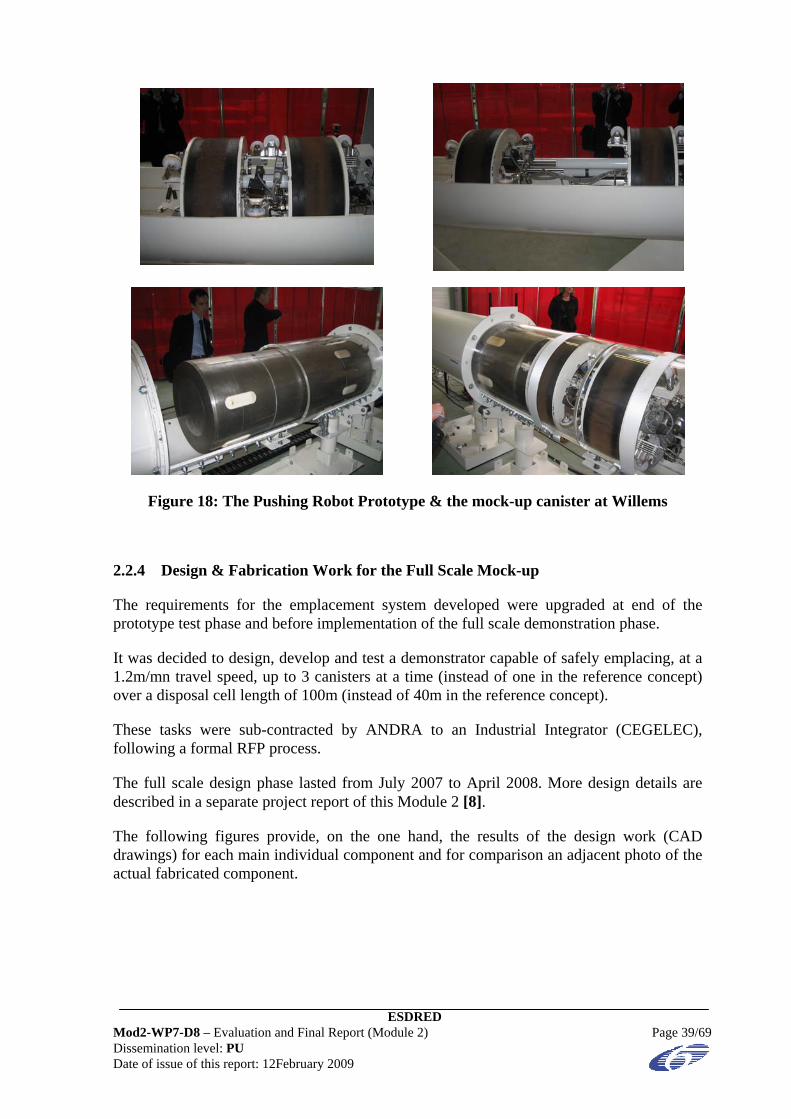
Figure 18: The Pushing Robot Prototype & the mock-up canister at Willems
2.2.4 Design & Fabrication Work for the Full Scale Mock-up
The requirements for the emplacement system developed were upgraded at end of the prototype test phase and before implementation of the full scale demonstration phase.
It was decided to design, develop and test a demonstrator capable of safely emplacing, at a 1.2m/mn travel speed, up to 3 canisters at a time (instead of one in the reference concept) over a disposal cell length of 100m (instead of 40m in the reference concept).
These tasks were sub-contracted by ANDRA to an Industrial Integrator (CEGELEC), following a formal RFP process.
The full scale design phase lasted from July 2007 to April 2008. More design details are described in a separate project report of this Module 2 [8].
The following figures provide, on the one hand, the results of the design work (CAD drawings) for each main individual component and for comparison an adjacent photo of the actual fabricated component.
ESDRED Mod2-WP7-D8 – Evaluation and Final Report (Module 2) Page 39/69 Dissemination level: PU Date of issue of this report: 12February 2009

A disposal cell mouth and a liner mock-up providing the necessary length of 100m over which the C type canister emplacement is demonstrated:
Figure 19: Design & fabrication of disposal cell mouth & liner mock-up
ESDRED Mod2-WP7-D8 – Evaluation and Final Report (Module 2) Page 40/69 Dissemination level: PU Date of issue of this report: 12February 2009

A transfer cask providing appropriate shielding during the transport and emplacement process and containing on the inside the Pushing Robot and the C type canister:
Main Characteristics: Total Mass 30 t, height1.75 m, length 3.10 m, width 4.10 m
Figure 20: Design and fabrication of shielding cask
ESDRED Mod2-WP7-D8 – Evaluation and Final Report (Module 2) Page 41/69 Dissemination level: PU Date of issue of this report: 12February 2009

A transport shuttle consisting of a mobile vehicle equipped with a hydraulic pack and an air compressor system:
Main Characteristics: Total weight 8 t, height1 m, width 3.2 m, length 7.8m, mm
Performances: Max load 40 t, speed up to 15 m/mn, positioning accuracy < 10 mm
Figure 21: Design & fabrication of transport shuttle
ESDRED Mod2-WP7-D8 – Evaluation and Final Report (Module 2) Page 42/69 Dissemination level: PU Date of issue of this report: 12February 2009

An air cushion docking table with its 3 electrical screw jacks for precise and smooth connection of the transfer cask onto to the cell mouth:
Figure 22: Design & fabrication of docking table
ESDRED Mod2-WP7-D8 – Evaluation and Final Report (Module 2) Page 43/69 Dissemination level: PU Date of issue of this report: 12February 2009

Three (3) mock-up canisters with a mass and geometry similar to those of a real C type waste package:
Figure 23: Design & fabrication of a mock-up canister
ESDRED Mod2-WP7-D8 – Evaluation and Final Report (Module 2) Page 44/69 Dissemination level: PU Date of issue of this report: 12February 2009

A Pushing Robot designed to move up to 3 canisters into the horizontal disposal cell:
Main Characteristics: Mass 400 kg, OD 590 mm, length 1.50 m
Performances: Average travel speed 1.5m/min, pushing force 4000 daN
Figure 24: Design & fabrication of Pushing Robot
ESDRED Mod2-WP7-D8 – Evaluation and Final Report (Module 2) Page 45/69 Dissemination level: PU Date of issue of this report: 12February 2009

The emplacement system test bench: Figure 25 shows the arrangement of the transport and emplacement system as erected, in an underground emplacement drift mock-up. The general layout is designed to incorporate the various technical requirements and demonstration objectives. It shows the limited space available around the emplacement system with the transport cask in a docking position.
This installation was essential for checking and testing in particular the relevancy and effectiveness of the various contingency remedial devices developed. Finally Figure 25 shows the Demonstrator in its endurance testing configuration for which 100m of liner are installed (instead of only 40m as initially planned and presented in the Dossier 2005) to assess the potential for an extension of the disposal cell and also in order to assess more thoroughly the real operating time for a canister emplacement cycle.
Furthermore this full length liner provided an opportunity to check how reliable the winch and its spooling system are and whether the anticipated air pressure loss is detrimental or not to the effective functioning of the Pushing Robot (motorized by a pneumatic motor).
Figure 25: Conceptual view of the test configuration with the shuttle in a docking position inside the access drift mock-up
2.2.5 Implementation of Full Scale Mock-up Tests
Due to the lack of space available in the Bure URL, it was decided to perform the demonstration tests in a surface facility. For this purpose, a former workshop in Saint-Chamond, in the vicinity of Saint-Etienne (Loire Department) was rented and partially revamped. This building provided the necessary lifting means and length to simulate the
ESDRED Mod2-WP7-D8 – Evaluation and Final Report (Module 2) Page 46/69 Dissemination level: PU Date of issue of this report: 12February 2009

emplacement process of a C type canister into a 100m long horizontal disposal cell mock-up. The components of the emplacement system were locally assembled.
After erection of the full test bench (Figure 26), the test campaign per se could take place. The test programme comprised performance tests and other tests to resolve operational breakdowns so that contingency plans were developed and implemented. Once all the test configurations were positively passed and solved, a total of approximately 500 hours of operations was carried out in order to obtain information on the reliability of the entire system and of each main component.
Figure 26: General View of the Full Scale Horizontal Emplacement Demonstrator as set up in Saint-Chamond
2.2.6 Summary and Analysis of the Main Achievements
It can be stated that the development, the fabrication and the performance of demonstration tests of the Pushing Robot system at full scale was also a success. All the components were designed in detail. The fabrication of all the system components was completed as planned.
After the individual main components were accepted during the FAT (Factory Acceptance Tests) during the months of April and May 2008, the components were delivered to the test site between June and mid August 2008.
ESDRED Mod2-WP7-D8 – Evaluation and Final Report (Module 2) Page 47/69 Dissemination level: PU Date of issue of this report: 12February 2009

ESDRED Mod2-WP7-D8 – Evaluation and Final Report (Module 2) Page 48/69 Dissemination level: PU Date of issue of this report: 12February 2009
Then, the complete test bench was assembled and erected in Saint-Chamond (near Saint-Etienne) from July to September 2008.
This was followed by the Site Acceptance tests (SAT) which lasted from October to November 2008 and then the demonstration and testing of the complete system. Finally the demonstration programme was prolonged by an endurance test campaign which lasted until the end of 2008.
The whole system turned out to be very rugged and reliable. No mechanical failures or design flaws could be identified. All the performance requirements were met, including the pushing of 3 canisters at a time instead of one as initially programmed at the start-up of ESDRED Module 2. The capacity to emplace canisters over an extended length of 100m (instead off 40m as per the ANDRA reference concept) was also demonstrated.
Only one piece of equipment (the upper part of the electrical screw jacks used for elevating the docking table) showed an abnormal wear (but no breakage occurred) when a dismantling of all the moving pieces took place for inspection and evaluation of the “wear factor”. This weak point (which does not put the disposal system in question) is still undergoing investigation at time of writing.
2.2.7 Possible Improvements of the Design Developed
Two important lessons learned are that the “weak points” of a machine are seldom those expected at time of design (in the present case, the anticipated wear was focused on the Pushing Robot components, which showed virtually no wear at all) and that endurance testing is mandatory.
Outside the ESDRED programme, ANDRA decided to run, in January 2009, an additional test configuration called the “S type curve” test, in which an exaggerated theoretical shape of a TBM (Tunnel Boring Machine) bore hole trajectory is simulated, such that the axis of the excavated (drilled) bore hole is not straight but curved.
This additional test is illustrated below in Figure 23. The results obtained were also quite satisfactory and showed that the system can cope with the potential geometrical defects of a bored disposal cell. These defects can be created during the boring process or later on due to geotechnical phenomena (stresses or movement of the rock) capable of bending the disposal cell steel casing/liner inside which the canisters are later emplaced. The only noticeable difference during the testing was an increase of the pushing force needed to move the canisters forward, but this increase was not detrimental to an effective and smooth emplacement process.
A further improvement (also outside of ESDRED) is also envisaged. In the year to come, i.e. after erection and start-up of the test bench at the CTe (showroom), a new type of ceramic sliding runner will be tested (their shape has been slightly modified, with a lower rugosity coefficient). The new ceramic runners would be made of zircon instead of alumina, which should make it possible to reduce the friction coefficient (hence the pushing force exerted on the canister by the Pushing Robot) by at least 20%.
Figure 27: View the Horizontal Emplacement Demonstrator in the S type Configuration
ESDRED Mod2-WP7-D8 – Evaluation and Final Report (Module 2) Page 49/69 Dissemination level: PU Date of issue of this report: 12February 2009

ESDRED Mod2-WP7-D8 – Evaluation and Final Report (Module 2) Page 50/69 Dissemination level: PU Date of issue of this report: 12February 2009
2.3 Retrievability Desk Study (NRG)
2.3.1 Framework
The emplacement of radioactive waste in a geological disposal facility is generally considered without any intent for retrieval. However, the issue of retrievability1 is increasingly looked upon as important for enhancing confidence amongst stakeholder groups as well as to increase the level of flexibility and, thus, the ability to respond to changes in technical information and policy factors. Besides the normal control and surveillance of the disposal operation, the concept of retrievability requires the possibility for reversal of operational steps if desired. Such reversal of operational steps can only be ensured if specific technological measures (e.g. the construction of disposal cells from which waste packages can safely be recovered) are already implemented in the design of the repository.
One of the topics of the ESDRED project concerned the assessment of existing geological disposal concepts from the perspective of retrievability and reversibility2. This assessment is performed in the “Retrievability Desk Study” (Work Package 4 of ESDRED’s module 2), which comprises the following two tasks as established in the third technical module meeting:
1. Performing a review of retrievability measures in the current disposal concepts of the countries participating in ESDRED;
2. Performing two specific retrievability case studies that represent the two main disposal concepts within ESDRED’s module 2: the German vertical (borehole) concept (as described in Section 2.1) and the French horizontal (disposal cell) concept (as is illustrated in more detail in Section 2.2).
2.3.2 Objective and scope
Since the retrieval of radioactive waste from a geological repository includes many aspects, the objectives of the desk study had to be defined more explicitly. Based on the objectives of ESDRED it was decided during the third technical module meeting to exclude non-technical issues like political, economical, social and ethical aspects. In addition, the desk study should comply with the time frame of the ESDRED project. Hence, it was decided to confine the review to the operational phase of the repository in which possibly some design base accidents (as a result of earthquakes, water intrusion, etc.) might be taken into account.
The potential retrievability measures in the studied disposal concepts have been evaluated along the three basic conditions, which determine the extent of retrievability provided by a particular disposal system, being:
• Accessibility of waste packages; 1 Retrievability is the ability provided by the repository system to retrieve the waste packages for whatever
reason retrieval might be wanted for (EUR 19145). 2 Reversibility is the ability of a repository system to allow the reversal of the steps in its development for
whatever reason (EUR 19145).

ESDRED Mod2-WP7-D8 – Evaluation and Final Report (Module 2) Page 51/69 Dissemination level: PU Date of issue of this report: 12February 2009
• Confinement of the waste in the waste packages; and
• Technical feasibility of retrieving the waste packages.
On this basis the ESDRED retrievability desk study has focused on the retrieval of waste packages (accessibility) as well as on the availability of equipment and the constraints for retrieval induced by the ambient environment (technical feasibility). In view of the small time window to be considered within ESDRED (only the operational phase) confinement of the waste (i.e. the integrity of the waste packages) is not likely to be a relevant issue, so this aspect got less attention in the study.
2.3.3 Task 1: Review current disposal concepts
Work approach
The approach to Task 1 of the review was to seek information from each of the partner organisations on their current national disposal concepts from the perspective of retrievability. Rather than doing this by means of a questionnaire, NRG had documented, as a first step, its understanding of the different national positions, using the information provided for each country in the European Commission Reports EUR 19145 (“Concerted action on the retrievability of long-lived radioactive waste in deep underground repositories”) and EUR 21025 (“Thematic network on the role of monitoring in a phased approach to geological disposal of radioactive waste”). The NRG summary document was then provided to each of the participants.
Each participating organisation was requested:
• to update or correct the information for their own country in terms of current policy and the current national strategy concerning retrievability;
• to add any pertinent comments; and
• to provide references to relevant published documents setting out the national policy and strategy.
Findings
A comparison of the disposal concepts relevant to ESDRED showed that there exist a wide range of national requirements concerning the extent to which the development of a waste disposal facility should be reversible prior to closure. For example, France has a policy requirement that each step of a repository development process, up to emplacement of the waste, is easily reversible. In contrast, Germany currently has no requirement concerning reversibility or waste retrievability in the context of any future geological disposal. Within this spectrum, most national disposal concepts aim to show that waste could be retrieved during the operational period of a repository, if so desired in future for whatever reason, though only limited provisions are intentionally incorporated in the design to facilitate easy retrieval of the waste.
Potential design measures that enhance retrievability of waste prior to repository closure are primarily aimed at providing easier accessibility to the waste packages (1), particularly in clay and salt host environments, and/or providing an improved capability to retrieve the

ESDRED Mod2-WP7-D8 – Evaluation and Final Report (Module 2) Page 52/69 Dissemination level: PU Date of issue of this report: 12February 2009
waste packages (2). Potential design measures in the first category include enhancing the stability of openings (e.g. by incorporating concrete or steel liners) and, in the second category, provision of easily removable buffer materials (e.g. in the form of pre-fabricated bentonite blocks).
In most disposal concepts relevant to ESDRED these issues are still under consideration and definite positions may not be reached until countries are much closer to starting the development phase. Likewise, operational and monitoring strategies are still under development. For some disposal concepts, this may mean that access ways will remain open for perhaps several decades whilst greater levels of confidence in the disposal concept are achieved, e.g. as a result of ongoing monitoring of the disposal system. For other concepts, it is likely that intensive monitoring activities will be focused on a special facility with closure of accesses to the main facility taking place relatively sooner, on the basis that the risk of neglect or even from deliberate intrusion is thereby significantly reduced.
The findings of the review were recorded in a public ESDRED Memorandum published on 30 May 2005 and subsequently put on the ESDRED web site (www.esdred.info).
2.3.4 Task 2: Specific retrievability case studies
Work approach
As part of task 2, retrievability case studies were performed on the (conceptual) disposal concepts within ESDRED’s module 2, viz. the French horizontal emplacement technique (Section 2.2) and the German vertical borehole disposal concept (Section 2.1).
Because of the advanced status of the French horizontal disposal design with respect to the incorporation of the concept of retrievability, it was decided that the retrievability desk study for the French disposal technique would take the form of a peer review. The safety concept of the German vertical disposal concept is based upon a rapid and permanent isolation of the emplaced waste by the host rock itself. Hence, it was decided that the retrievability desk study for the German disposal technique would focus on generating potentially technically feasible ideas for retrieval of what are effectively considered to be non–retrievable waste packages once they are emplaced.
Findings
Deliverable 4 of module 2 (Mod2-WP4-D43) describes in detail the peer review carried out for the French horizontal disposal concept, focusing on the so-called C-type waste (vitrified reprocessing waste). First the interpretation of the retrievability concept is compared to the present state of the art, after which in subsequent sections the details with respect to construction, normal operation and closure of the design facility as well as the possible retrieval operations at different stages in the repository development are reviewed, including safety considerations. The case study concludes with an overview of the results of the peer review.
3 ESDRED’s Deliverable 4 of Module 2 Retrievability Desk Study (Mod2-WP4-D4) has a dissemination
level restricted to a group specified by the ESDRED partners.

ESDRED Mod2-WP7-D8 – Evaluation and Final Report (Module 2) Page 53/69 Dissemination level: PU Date of issue of this report: 12February 2009
The peer review conducted for ANDRA’s design of a repository for retrievable disposal of radioactive waste has shown that in general the design agrees quite well with the present state of the art concerning the retrievability concept. In all stages of repository development the three basic retrievability conditions, mentioned in Section 2.3.2, have been observed extensively. The review led also to a number of detailed comments that can be dealt with in due course without serious implications
Report Mod2-WP4-D4 describes also in detail the review carried out for the German vertical concept for geological disposal in rock salt, focusing on the emplacement of BSK-3 canisters (spent fuel). In subsequent sections, details are provided with respect to the construction, normal operation and closure of the repository as well as some technical feasible ideas for retrieval operations at different stages in the repository development, including safety considerations.
The assessment conducted for the German design of a repository for disposal of radioactive waste in deep vertical boreholes has shown that in general the design agrees well with present state of the art concerning geological disposal. The review led also to some detailed comments with respect to the construction of a deep geological repository in salt, the emplacement operations, and the topic of retrievability of waste packages. In most cases these comments can be dealt with in due course without serious implications for the German borehole concept.
2.3.5 Conclusions
A comparison of the disposal concepts relevant to ESDRED (performed as Task 1 of the Retrievability Desk Study) showed that there exists today a wide range of national requirements concerning the extent to which the development of a waste disposal facility should be reversible prior to closure. For example, France now has a law which says that a repository must be shown to be reversible for at least 100 years before an operating licence can be granted. By way of contrast, Germany currently has no requirement concerning reversibility or waste retrievability in the context of any future geological disposal. Within this broad spectrum, most national disposal concepts aim to show that waste could be retrieved during the operational period of a repository, if so desired in the future for whatever reason, though only limited provisions are intentionally incorporated in the design to facilitate easy retrieval of the waste.
The peer review conducted for the French design of a repository for retrievable disposal of radioactive waste (denoted as Task 2 of the retrievability desk study) has shown that in general the design agrees quite well with the present state of the art concerning the retrievability concept. In all stages of repository development the three basic retrievability conditions (noted in Section 2.3.2) have been observed extensively. The review led also to a number of very specific comments that can be dealt with in due course without serious implications.
The assessment conducted for the German repository design for disposal of radioactive waste in deep vertical boreholes (also part of Task 2 of the retrievability desk study) has shown that in general the design agrees well with the present state of the art concerning geological disposal. This assessment also led to some very specific comments with respect to the construction of a deep geological repository in rock salt, the emplacement operations,

ESDRED Mod2-WP7-D8 – Evaluation and Final Report (Module 2) Page 54/69 Dissemination level: PU Date of issue of this report: 12February 2009
and the topic of retrievability of waste packages. Here too most of the comments on this design can be dealt with in due course without serious implications for the German borehole concept.

ESDRED Mod2-WP7-D8 – Evaluation and Final Report (Module 2) Page 55/69 Dissemination level: PU Date of issue of this report: 12February 2009
3 SUMMARY AND CONCLUSIONS
3.1 Conclusions Related to the Testing of the BSK 3 Emplacement System (DBE TECHNOLOGY)
It can be stated that the development, the fabrication and the performance of demonstration tests of the BSK 3 emplacement system was a success. All the components have been designed in detail, the drawings and reports evaluated by external experts confirming the compliance with the regulatory requirements of the German Mining Regulations and Atomic Energy Act. The components were fabricated on a full-scale basis between summer 2007 and spring 2008. The construction work to prepare a suitable test platform was successfully accomplished by April 2008. The individual components (mining locomotive, transport cart, BSK 3 dummy, transfer cask, emplacement device and borehole lock) were delivered to the test site between April and June 2008. After the individual components had been accepted on site (SAT), the demonstration programme - performed in two shifts because of unforeseen delays in fabrication and installation of the emplacement device - was started in August 2008 and lasted until the end of the project. However, the reliability of the emplacement system was confirmed by means of a large number of demonstration tests (several hundreds of cycles) and conclusions and recommendations were drawn for the industrial application in a real repository.
The successful demonstration programme led to the decision not to dismantle the entire transport and emplacement system after the end of the ESDRED project but to use the system for a second type of waste canister. The idea is to investigate as well its reliability for handling and emplacing so-called triple-packs of HLW-canisters instead of a BSK 3 canister. Accordingly additional demonstration tests will be performed in the spring of 2009 outside the scope of the ESDRED project. In this case three (3) canister dummies will be encapsulated by a thin steel wall envelope thus providing geometry and mass similar to the BSK 3 canister. This encapsulation is the prerequisite for the emplacement process with the same transport and emplacement system already successfully tested for the BSK 3 canisters.
One lesson learned during the fabrication of the different components of the BSK 3 emplacement system was that there is a need to control and/or monitor all steps of a component fabrication process on an ongoing basis in spite of having very precisely formulated the technical specifications and having produced precise drawings.
3.2 Conclusions Related to the Tests of the Pushing Robot System for C Type Canister Emplacement (ANDRA)
It can be stated that the development, the fabrication and the performance of demonstration tests of the Pushing Robot system for C type canister emplacement was also a success. All the components were designed in detail. The fabrication of all the system components was completed as planned. After the individual main components had been accepted during the FAT (Factory Acceptance Tests), the complete test bench was assembled and erected in Saint-Chamond (near Saint-Etienne). This was followed by the Site Acceptance tests (SAT) and the demonstration and testing of the complete system. The demonstration programme was prolonged by an endurance test campaign which also proved satisfactory.

ESDRED Mod2-WP7-D8 – Evaluation and Final Report (Module 2) Page 56/69 Dissemination level: PU Date of issue of this report: 12February 2009
The whole system turned out to be very rugged and reliable. No mechanical failures or design flaws could be identified. All the performance requirements were met, including the pushing of 3 canisters at a time instead of one as initially programmed at the start-up of ESDRED Module 2. Only one piece of equipment (the upper part of the electrical screw jacks used for elevating the docking table) showed an abnormal wear (but no breakage occurred) when a dismantling of all the moving pieces took place for inspection and evaluation of the “wear factor”. This weak point (which does not put the disposal system in question) is still undergoing investigation at time of writing.
Two important lessons learned are that the weak points of a machine are seldom those expected (in the present case, the anticipated wear was focused on the Pushing Robot components, which showed virtually no wear at all) and that endurance testing is mandatory.
Outside the ESDRED programme, ANDRA decided to run in January 2009 an additional test configuration called the “S type curve” test, in which an exaggerated theoretical shape of a TBM (Tunnel Boring Machine) bore hole trajectory is simulated such that the axis of the excavated (drilled) bore hole is not straight but curved. The results obtained were also quite satisfactory and showed that the system can cope with the potential geometrical defects of a bored disposal cell. These defects can be created during the boring process or later on due to geotechnical phenomena (stresses or movement of the rock) capable of bending the cell steel casing/liner inside which the canisters are later emplaced). The only noticeable difference during the testing was an increase of the pushing force needed to move the canisters forward, but this increase was not detrimental to an effective and smooth emplacement process.
A further improvement (also outside of ESDRED) is now also envisaged. In the year to come, i.e. after erection and start-up of the test bench at the CTe (showroom), a new type of ceramic sliding runner will be tested (their shape has been slightly modified, with a lower rugosity coefficient). The new ceramic runners will be made of zircon instead of alumina, which should make it possible to reduce the friction coefficient (hence the pushing force exerted on the canister by the Pushing Robot) by at least 20%.
3.3 Conclusions Related to the Retrievability Case Studies (NRG)
A comparison of the disposal concepts relevant to ESDRED (performed as Task 1 of the Retrievability Desk Study) showed that there exists today a wide range of national requirements concerning the extent to which the development of a waste disposal facility should be reversible prior to closure. For example, France now has a law which says that a repository must be shown to be reversible for at least 100 years before an operating licence can be granted. By way of contrast, Germany currently has no requirement concerning reversibility or waste retrievability in the context of any future geological disposal. Within this broad spectrum, most national disposal concepts aim to show that waste could be retrieved during the operational period of a repository, if so desired in the future for whatever reason, though only limited provisions are intentionally incorporated in the design to facilitate easy retrieval of the waste.
The peer review conducted for the French design of a repository for retrievable disposal of radioactive waste (denoted as Task 2 of the retrievability desk study) has shown that in

ESDRED Mod2-WP7-D8 – Evaluation and Final Report (Module 2) Page 57/69 Dissemination level: PU Date of issue of this report: 12February 2009
general the design agrees quite well with the present state of the art concerning the retrievability concept. In all stages of repository development the three basic retrievability conditions (noted in Section 2.3.2) have been observed extensively. The review led also to a number of very specific comments that can be dealt with in due course without serious implications.
The assessment conducted for the German repository design for disposal of radioactive waste in deep vertical boreholes (also part of Task 2 of the retrievability desk study) has shown that in general the design agrees well with the present state of the art concerning geological disposal. This assessment also led to some very specific comments with respect to the construction of a deep geological repository in rock salt, the emplacement operations, and the topic of retrievability of waste packages. Here too most of the comments on this design can be dealt with in due course without serious implications for the German borehole concept.
ESDRED Mod2-WP7-D8 – Evaluation and Final Report (Module 2) Page 58/69 Dissemination level: PU Date of issue of this report: 12February 2009
4 LIST OF REFERENCES
[1] “Input Data and Functional Requirements” (Project Deliverable Mod2 WP1 D1).
[2] “Report on Conceptual Design” (Project Deliverable Mod2 WP2.1 D2).
[3] “Report on Pushing Robot Prototype” (Project Deliverable Mod 2 WP2.2 D9).
[4] “Report on Basic Design/Vertical Emplacement” (Project Deliverable Mod2 WP3 D3.1).
[5] “Report on Basic Design/Horizontal Emplacement” (Project Deliverable Mod2 WP3 D3.2).
[6] “Report on Retrievability Study” (Project Deliverable Mod2 WP4 D4).
[7] “Report on Detailed Design/Vertical concept” (Project Deliverable Mod2 WP5 D5.1).
[8] “Report on Detailed Design/Horizontal concept” (Project Deliverable Mod2 WP5 D5.2).
[9] “Report on Fabrication & Commissioning” (Project Deliverable Mod2 WP6.1 D6).
[10] “Report on In situ Implementation” (Project Deliverable Mod2 WP6.2 D7).
[11] “Photo Report of the Grand Opening for the Vertical Emplacement Concept on September, 9 2008”
ESDRED Mod2-WP7-D8 – Evaluation and Final Report (Module 2) Page 59/69 Dissemination level: PU Date of issue of this report: 12February 2009
ANNEX 1: LIST OF ORGANISATIONS & PEOPLE WHO PARTICIPATED IN ESDRED MODULE 2
The following organisations were engaged in the Research & Development work carried out within the frame of ESDRED Project Module 2:
ANDRA, France, NRG, The Netherlands, DBE TECHNOLOGY, Germany. Furthermore, DBE TECHNOLOGY acted as
Module 2 Leader.
The main subcontractors involved in the design, manufacturing and testing of the concerned demonstrators were:
MUSTHANE (France) & CEGELEC (France) for the ANDRA related activities, SIEMAG, GNS, Schalker Eisenhütte, Ammersbach (Germany) for the DBE-
TECHNOLOGY related activities, NRG worked only in house for its expert review tasks related to reversibility.
The following persons participated in ESDRED Module 2:
Company Name First Name
ANDRA BOSGIRAUD Jean-Michel
ANDRA GUENIN Jean-Jacques
ANDRA SEIDLER Wolf
DBE TECHNOLOGY BOLLINGERFEHR (Note 1) Wilhelm
DBE TECHNOLOGY FILBERT Wolfgang
DBE TECHNOLOGY WEHRMANN Jobst
DBE TECHNOLOGY NIEHUES Norman
NRG HAVERKATE Benno
NRG HART Jap
NRG POLEY Arjen
NRG O’SULLIVAN Patrick
Note 1: Wilhelm BOLLINGERFEHR also acted as Module 2 Leader Representative

ESDRED Mod2-WP7-D8 – Evaluation and Final Report (Module 2) Page 60/69 Dissemination level: PU Date of issue of this report: 12February 2009
ANNEX 2: LIST OF MODULE 2 DELIVERABLES COMPLETE WITH DISSEMINATION LEVEL
Reference Title Date Dissemination Level
WP1: Input Data and Functional Requirements
Mod2-WP1-D1.1 “Input Data and Functional Requirements” 23/05/2007 (Rev.1) PU
WP2.1: Conceptual Design
Mod2-WP2.1-D2 “Conceptual Design” 14/10/2005 RE
WP2.2: Prototype Test for Spent Fuel Canister
Mod2-WP2.2-D9 “Report on Pushing Robot Prototype Test” 10/03/2006 RE
WP3: Basic Design
Mod2-WP3-D3.1 “Basic Design - Vertical Emplacement” 31/07/2006 CO
Mod2-WP3-D3.2 “Basic Design - Horizontal Emplacement” 30/01/2008 CO
WP4: “Retrievability Desk Study”
Mod2-WP4-D4 “Retrievability Desk Study” 25/05/2007 RE
WP5: Detail Design
Mod2-WP5-D5.1 Detail Design (Vertical concept) 08/05/2008 CO
Mod2-WP5-D5.2 Detail Design (Horizontal concept) 14/10/2008 CO
WP6: Full Scale Demonstration
Mod2-WP6-D6 “Commissioning Report” F 20/02/2009 CO
Mod2-WP6-D7 “Report on Emplacement tests” F 06/03/2009 CO
WP7: Evaluation & Final Report
Mod2-WP7-D8 “Final Report & Evaluation” Date of this Report PU
Dissemination Level: PU: Public / RE: Restricted / CO: Confidential

ESDRED Mod2-WP7-D8 – Evaluation and Final Report (Module 2) Page 61/69 Dissemination level: PU Date of issue of this report: 12February 2009
ANNEX 3: LIST OF ESDRED FINAL REPORTS
Reference Title Dissemination Level
Mod1-WP6-D6 Module 1 (Buffer Construction Technology) Final Report PU
Mod2-WP7-D8 Module 2 (Waste Canister Transfer & Emplacement Technology) Evaluation and Final Report
PU
Mod3-WP5-D6 Module 3 (Heavy Load Emplacement Technology) Evaluation and Final Report
PU
Mod4-WP4-D9 Module 4 (Temporary Sealing Technology) Evaluation and Final Report
PU
Mod5-WP5-D11 Final Report on Communication Actions PU
Mod5-WP9-D12 Leaflet on ESDRED Results PU
Mod6-WP4-D6 Final Summary Report PU
Dissemination Level: PU: Public / RE: Restricted / CO: Confidential

ESDRED Mod2-WP7-D8 – Evaluation and Final Report (Module 2) Page 62/69 Dissemination level: PU Date of issue of this report: 12February 2009
ANNEX 4: LIST OF ACRONYMS
ABBREVIATION MEANING
µSv Micro-sievert
ALARA As Low As Reasonably Achievable
BH Borehole
BSK 3 German thin walled fuel rod canister (Brennstabkokille 3)
BWR Boiling Water Reactor
C Waste Canister Containing High Level Vitrified Waste (ANDRA)
CU Spent Fuel Canister (ANDRA)
CU1 SF Waste Canister Containing 4 Spent Fuel Rods (ANDRA)
CU2 SF Waste Canister Containing 1 Spent Fuel Rod (ANDRA)
D1 Deliverable 1
EB Engineered Barrier
EBS Engineered Barrier System
EIA Environmental Impact Assessment
ESDRED Engineering Studies and Demonstrations of Repository Designs
GNB Gesellschaft für Nuklearbehälter mbH now part of GNS - Company for Nuclear Service Ltd.
HLW High Level Waste
HRL Hard Rock Laboratory
ICRP International Commission of Radiation Protection
ID Inside Diameter
ILW Intermediate Level Waste (synonym for MLW)
IPC Integrated Project Coordinator
KBS-3H SKB/POSIVA Horizontal Disposal Concept (ESDRED Reference)
KBS-3V SKB/POSIVA Vertical Disposal Concept (National Reference)
KTA German Nuclear Safety Standards Commission
ESDRED Mod2-WP7-D8 – Evaluation and Final Report (Module 2) Page 63/69 Dissemination level: PU Date of issue of this report: 12February 2009
ABBREVIATION MEANING
LILW Low and Intermediate Level Waste
LL Long Lived
LT Long Term
LWR German equivalent of PWR or Pressurized Water Reactor
MLW Medium Level Waste
Mod1 Module 1
MPa Mega Pascal
mSv Milli-Sievert
N/A Not Applicable
NPP Nuclear Power Plant
O/N ONDRAF/NIRAS
OD Outside Diameter
OPC Ordinary Portland Cement
pH Unit of measure for acidity and alkalinity of a material
Pkg Package
PWR Pressurized Water Reactor
QA Quality Assurance
QC Quality Control
RB Rock Bolt
Rc Resistance to compression
RFP Request for Proposal
SF Spent Fuel
SL Short Lived
Sv Sievert
U/G Underground
UCS Unconfined Compressive Strength

ESDRED Mod2-WP7-D8 – Evaluation and Final Report (Module 2) Page 64/69 Dissemination level: PU Date of issue of this report: 12February 2009
ABBREVIATION MEANING
URL Underground Research Laboratory
UVP German for “Environmental Impact Assessment”
Vw Vitrified (High Level) Waste
VHLW Vitrified High Level Waste
WPi Work Package i
ESDRED Mod2-WP7-D8 – Evaluation and Final Report (Module 2) Page 65/69 Dissemination level: PU Date of issue of this report: 12February 2009
ANNEX 5: GLOSSARY
WORD Per IAEA
DEFINITION
ALARA yes An optimisation process for determining what level of protection and safety makes exposures, and the probability and magnitude of potential exposures, “as low as reasonably achievable, economic and social factors being taken into account”.
Backfill yes The material used to refill excavated portions of a repository (drifts, disposal rooms or boreholes) during and after waste has been emplaced
Barrier yes A physical obstruction that prevents or delays the movement of radio nuclides or other material between components of a system, for example a waste repository. In general a barrier can be an engineered barrier (see EBS below) or a natural or geological barrier.
Behind away from the dead end of a disposal cell/drift
Bentonite yes A soft light colored clay formed by chemical alteration of volcanic ash. It is composed essentially of montmorillonite and related minerals of the smectite group. Bentonite is used as backfill and buffer material in repositories.
Buffer yes Any substance placed around a waste package in a repository to serve as an additional barrier to: stabilize the surrounding environment; restrict the access of groundwater to the waste package; and reduce by sorption the rate of eventual radionuclide migration from the waste
Canister See « waste container »
Cask yes A vessel for the transport and/or storage of spent fuel and other radioactive materials. The cask serves several functions. It provides chemical, mechanical, thermal and radiological protection, and dissipates decay heat during handling, transport and storage.
Clay Within ESDRED this refers to indurated clay in the form of clay stones and argillites. Clays differ greatly mineralogically and chemically but ordinarily their base is hydrous aluminum silicate. NB: “Swelling clays” refers to specific types of clays used in EBS (see “Bentonite”) and in seals.
Conditioning yes Those operations that produce a waste package suitable for handling, transport, storage and/or disposal. Conditioning may include the conversion of the waste to a waste form, enclosure of the waste in canisters, and, if necessary, providing an over pack.

ESDRED Mod2-WP7-D8 – Evaluation and Final Report (Module 2) Page 66/69 Dissemination level: PU Date of issue of this report: 12February 2009
WORD Per IAEA
DEFINITION
Criticality Per US Nuclear
Regulatory
Commission
A term used in reactor physics to describe the state when the number of neutrons released by fission is exactly balanced by the neutrons being absorbed (by the fuel and poisons) and escaping the reactor core. A reactor is said to be "critical" when it achieves a self-sustaining nuclear chain reaction, as when the reactor is operating. In waste disposal designs the objective is to keep any fissile material in a sub-critical state so that any heat generated is due to natural decay only.
Decline An excavation, in rock, for providing access from surface to the underground. Also called a ramp or access ramp. Essentially an inclined tunnel.
Demonstrator A custom designed prototype piece of equipment built to prove a design concept and to show that it works; hence used to demonstrate.
Disposal yes The emplacement of waste in an appropriate facility without the intention of retrieval i.e. permanently.
Disposal Cell Typically a short tunnel/drift/borehole excavated in an underground repository for the purpose of disposing packages of radioactive waste.
Disposal Drift Typically a long tunnel/drift excavated in an underground repository for the purpose of disposing packages of radioactive waste
Disposal Package
The final Waste Package which is placed into a repository without further conditioning i.e. the Super-Container, the Primary Package with over pack or the Primary Package without over pack.
Drift A horizontal or nearly horizontal mined passageway
EBS yes Engineered barrier system; the designed or engineered components of a repository including waste packages and other engineered barriers. See also definition of barrier above.
EDZ Excavation damage zone; used to describe the area surrounding a rock excavation which has been altered from its initial state usually by the formation of fractures or micro fissures.
ESDRED Concept
This is a variation of the reference National Concept which is used within the ESDRED Project. Example: Sweden's national concept is "Vertical" however SKB's concept within ESDRED is horizontal
Front, in front of
towards the dead end of a disposal cell/drift
Functional Requirements
Generally refers to expected functions and associated levels of performance that must be met by one or several design elements. Within ESDRED, similar to flexible design criteria or flexible input data; generally refers to criteria or elements that are open to discussion and/or negotiation

ESDRED Mod2-WP7-D8 – Evaluation and Final Report (Module 2) Page 67/69 Dissemination level: PU Date of issue of this report: 12February 2009
WORD Per IAEA
DEFINITION
Gate A type of radiation protection door installed on a cask as well as on the head of a disposal cell.
Hoist A machine, driven by an electric motor, used to raise or lower a conveyance in a shaft.
HRL Like a URL (see below) but located in hard crystalline rock.
Implementer The private corporation or public body responsible for constructing and operating a repository.
Input Data Within ESDRED, similar to fixed design criteria; generally refers to criteria or elements that are unavoidable and not open to discussion and/or negotiation
Long Term Generally intended to mean extending in time beyond the final closure of a repository
Matrix A non-radioactive material used to immobilize waste. Examples of matrices are bitumen, cement, various polymers and glass
Matrix diffusion
Diffusion of solutes from a water-bearing fracture to pores and microfractures of the adjacent rock matrix and vice versa
Overpack yes A secondary (or additional) outer container for one or more waste packages, used for handling, transport, storage or disposal.
Plug Sometimes used interchangeably with SEAL but not within ESDRED where it refers to a concrete mass that serves as a backstop or abutment to resist the pressures eventually exerted on a seal by the swelling buffers.
Primary Package
A package of radioactive material as delivered by the producer; before conditioning, for disposal
Ramp See decline.
Repository A nuclear facility where waste is emplaced for disposal
Repository system
The combination of the repository and the host rock
Retrievability The ability provided by the repository system, to retrieve waste packages for whatever reason retrieval might be wanted for.
Reversibility Implies a step wise disposal process and in particular refers to the ability of a repository system, for whatever reason, to reverse the steps that have been executed so far in its development.
Safety Case yes An integrated collection of arguments and evidence to demonstrate the safety of a facility. This will normally also include a safety assessment.

ESDRED Mod2-WP7-D8 – Evaluation and Final Report (Module 2) Page 68/69 Dissemination level: PU Date of issue of this report: 12February 2009
WORD Per IAEA
DEFINITION
Salt One of the 3 main host rocks being considered worldwide for the disposal of highly active waste materials.
Seal yes Engineered barriers placed in passages within and leading to a repository to isolate the waste and to prevent seepage leakage of water into or radionuclide migration from the repository area. Sealing is performed as part of repository closure process.
Shaft A vertical access way, excavated in rock, used to connect the surface with one or more horizons underground. Typically outfitted with one or more hoist and one or more conveyances unless used exclusively for ventilation in which case it may be left bald.
Shielding yes A material interposed between a source of radiation and persons, or equipment or other objects, in order to absorb radiation and thereby reduce radiation exposure.
Shotcrete Mortar or concrete pneumatically projected onto a surface at high velocity.
Spent Fuel yes Nuclear fuel removed from a reactor following irradiation, which is no longer usable in its present form because of depletion of fissile material & build up of poison or radiation damage.
Storage yes The holding of spent fuel of radioactive waste in a facility that provides for its containment, with the intention of retrieval. Storage is by definition an interim measure.
Super-Container
Generally seen as a disposal package that, unlike other disposal packages also incorporates bentonitic or cementitious buffer material.
Transmutation yes The conversion of one element into another. Transmutation is under study as a means of converting longer lived radionuclides into shorter lived or stable radionuclides.
Transuranic Waste
Alpha bearing waste that consists of material contaminated with elements that have atomic numbers greater than that of uranium (92), the heaviest natural element.
URL yes Underground Research Laboratory constructed for the purpose of conducting in situ testing. The objective is to conduct tests in a geological environment that is essentially equivalent to the environment of a potential repository.
Waste Material in gaseous, liquid or solid form for which no further use is foreseen

ESDRED Mod2-WP7-D8 – Evaluation and Final Report (Module 2) Page 69/69 Dissemination level: PU Date of issue of this report: 12February 2009
WORD Per IAEA
DEFINITION
Waste Container
yes The vessel into which the waste form is placed for handling, transport, storage and/or eventual disposal; also the outer barrier protecting the waste from external intrusions. The waste container is a component of the waste package. For example, the “canister” into which molten HLW glass would be poured.
Waste form Waste in its physical and chemical form after treatment and/or conditioning (resulting in a solid product) prior to packaging. The waste form is a component of the waste package
Waste Package
yes The product of conditioning that includes the waste form and any container(s) and internal barriers (e.g. absorbing materials and Liners), prepared in accordance with the requirements for handling, transport, storage and/or disposal.
Wireless Monitoring
System for monitoring phenomenology in front of a seal or plug without installing cables or wires through any of the barriers intended to isolate one or more disposal packages