Continuous level measurement in liquids and bulk solids ... - Hauser/documentazione/files... · and...
116
Products Solutions Services Continuous level measurement in liquids and bulk solids Selection and engineering guide for the process industry Level
Transcript of Continuous level measurement in liquids and bulk solids ... - Hauser/documentazione/files... · and...

Products Solutions Services
Continuous level measurement in liquids and bulk solidsSelection and engineering guide for the process industry
Leve
l
2
Legend
• Continuous level measurement in liquidsstarting page 3
• Continuous level measurement
in solids
starting page 77

Continuous level measurement in liquidsSelection and engineering guide for the process industry
Products Solutions Services
4
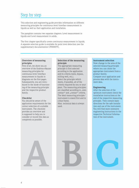
Step by step
This selection and engineering guide provides information on different
measuring principles for continuous level/interface measurement in
liquids as well as their application and installation.
The pamphlet contains two separate chapters: Level measurement in
liquids and Level measurement in solids.
The first chapter specifically covers continuous measurement in liquids.
A separate selection guide is available for point level detection (see the
supplementary documentation CP00007F).
Selection of the measuring
principle
The appropriate measuring
principle is first selected
according to the application
and its criteria (tank, bypass,
stilling well, etc.).
Select the principle which
meets, if possible, all of the
criteria required by you or your
plant. The measuring principles
are classified according to „non-
contact“ and „contact“ criteria.
The ideal measuring principle/
instrument is stated first and in
a blue frame.
Max. technical data is always
used.
Instrument selection
Now change to the area of the
selected measuring principle
where you can chose the
appropriate instrument from a
product family.
Compare your application and
process data with the instru-
ment data.
Engineering
After the selection of the
optimum instrument check the
installation instructions at the
end of the respective measuring
principle. They contain basic
directions for the safe installa-
tion and use of the instrument.
You will find more extensive
engineering instructions in the
respective Technical Informa-
tion of the instrument.
B C
Overview of measuring
principles
First of all, we show you an
overview of the Endress+Hauser
measuring principles for
continuous level/interface
measurement in liquids in
diagrams on the first pages.
Subsequently, you are intro-
duced to the mode of function-
ing of the measuring principle
and the respective product
family.
Checklist
You should be aware of the
application requirements for the
correct selection of a suitable
instrument. The checklist
provides an overview and
is supposed to help you to
consider or record this data as
completely as possible.
A
5
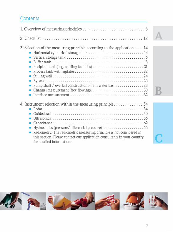
Contents
A
B
C
1. Overview of measuring principles . . . . . . . . . . . . . . . . . . . . . . . . . . . . 6
2. Checklist . . . . . . . . . . . . . . . . . . . . . . . . . . . . . . . . . . . . . . . . . . . . . 12
3. Selection of the measuring principle according to the application . . . . 14• Horizontal cylindrical storage tank . . . . . . . . . . . . . . . . . . . . . . . . . . . 14
• Vertical storage tank . . . . . . . . . . . . . . . . . . . . . . . . . . . . . . . . . . . . . . 16
• Buffer tank . . . . . . . . . . . . . . . . . . . . . . . . . . . . . . . . . . . . . . . . . . . . . 18
• Recipient tank (e. g. bottling facilities) . . . . . . . . . . . . . . . . . . . . . . . . . 21
• Process tank with agitator . . . . . . . . . . . . . . . . . . . . . . . . . . . . . . . . . .22
• Stilling well . . . . . . . . . . . . . . . . . . . . . . . . . . . . . . . . . . . . . . . . . . . . .24
• Bypass . . . . . . . . . . . . . . . . . . . . . . . . . . . . . . . . . . . . . . . . . . . . . . . . .26
• Pump shaft / overfall construction / rain water basin . . . . . . . . . . . . .28
• Channel measurement (free flowing) . . . . . . . . . . . . . . . . . . . . . . . . . .30
• Interface measurement . . . . . . . . . . . . . . . . . . . . . . . . . . . . . . . . . . . . 32
4. Instrument selection within the measuring principle . . . . . . . . . . . . . 34• Radar . . . . . . . . . . . . . . . . . . . . . . . . . . . . . . . . . . . . . . . . . . . . . . . . . .34
• Guided radar . . . . . . . . . . . . . . . . . . . . . . . . . . . . . . . . . . . . . . . . . . . .50
• Ultrasonics . . . . . . . . . . . . . . . . . . . . . . . . . . . . . . . . . . . . . . . . . . . . .56
• Capacitance . . . . . . . . . . . . . . . . . . . . . . . . . . . . . . . . . . . . . . . . . . . . . 62
• Hydrostatics (pressure/differential pressure) . . . . . . . . . . . . . . . . . . . .66
• Radiometry: The radiometric measuring principle is not considered in
this section. Please contact our application consultants in your country
for detailed information.

66
A 1. Overview of the measuring principles
Point level Continuous
Liquids VibronicsConductiveCapacitanceFloat switchRadiometrics
RadarGuided radarUltrasonics
Hydrostatics (p + dp)CapacitanceRadiometrics
Bulk solids VibronicsCapacitance
PaddleMicrowave barrier
Radiometrics
Guided radarRadar
UltrasonicsElectromechanical level
systemRadiometrics
Segmentation
Process conditions*
Temperature (°C)
Radar
Hydrostatics (p + dp)
Guided radar
Ultrasonics
Pressure(bar)
* Radiometry not depicted
Non-contact measurement from outside and, therefore, no application limits.
Capacitance

77
A
„You only pay what you really need“.
Endress+Hauser takes this statement seriously and offers a large number of different
measuring principles which vary in price and functionality.
Endress+Hauser offers you a solution adapted to your application and tailored to your
process requirements.
You can select the best technology for your application from the wide product range
of Endress+Hauser.

88
1. Overview of measuring principles
Radar
Micropilot works with high-frequency
radar pulses which are emitted by
an antenna and reflected from the
product surface. The time of flight of
the reflected radar pulse is directly
proportional to the distance traveled. If
the tank geometry is known, the level
can be calculated from this variable.
Micropilot
Non-contact, maintenance-free
measurement also under extreme
conditions. Unaffected by density,
temperature, conductibility and
humidity. No impairment by vapor
pressure.
• Process temperatures up to
+450°C/+842°F
• Process pressures up to
160bar/2320psi
Guided radar
Levelflex works with high-frequency
radar pulses which are guided along
a probe. As the pulse impacts the
medium surface, the characteristic
impedance changes and part of the
emitted pulse is reflected. The time
between pulse launching and receiving
is measured and analyzed by the
instrument and constitutes a direct
measure for the distance between the
process connection and the product
surface.
Levelflex
Reliable and maintenance-free
measurement in liquids, also in
turbulent media and foam. Unaffected
by density, temperature, conductibility
and humidity. No impairment by vapor
pressure. Measurement of interface
and level.
• Process temperatures up to
+450°C/+842°F
• Process pressures up to
400bar/5,800psi
Ultrasonics
Ultrasonic measurement is based on
the time-of-flight principle. A sensor
emits ultrasonic pulses, the surface of
the media reflects the signal and the
sensor detects it again.
The time of flight of the reflected
ultrasonic signal is directly proportional
to the distance traveled. With the
known tank geometry the level can be
calculated.
Prosonic S/M/T
Non-contact and maintenance-free
measurement without impairment by
product properties, e. g. dielectric
constant, conductivity, density or
humidity.
• Process temperatures up to
+150°C/+302°F
• Process pressures up to
3bar/44psi
A
c1
c2
p1
p2
99
A
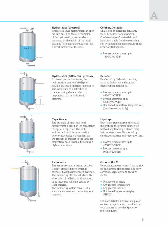
Hydrostatics (differential pressure)
In closed, pressurized tanks, the
hydrostatic pressure of the liquid
column causes a difference in pressure.
The same leads to a deflection of
the measuring element which is
proportional to the hydrostatic
pressure.
Deltabar
Unaffected by dielectric constant,
foam, turbulence and obstacles.
High overload resistance.
• Process temperatures up to
+400°C/+752°F
• Process pressures up to
420bar/6,090psi
• Unaffected by ambient temperatures
(Deltabar electronic dp)
Capacitance
The principle of capacitive level
measurement is based on the capacitance
change of a capacitor. The probe
and the tank wall form a capacitor
whose capacitance is dependent on
the amount of product in the tank: an
empty tank has a lower, a filled tank a
higher capacitance.
Liquicap
Exact measurement from the end of
the probe to the process connection
without any blocking distance. Very
fast response times. Unaffected by
density, turbulence and vapor pressure.
• Process temperatures up to
+200°C/+392°F
• Process pressures up to
100bar/1,450psi
Hydrostatics (pressure)
Hydrostatic level measurement in open
tanks is based on the determination
of the hydrostatic pressure which is
generated by the height of the liquid
column. The obtained pressure is thus
a direct measure for the level.
Cerabar, Deltapilot
Unaffected by dielectric constant,
foam, turbulence and obstacles.
Condensate-proof, watertight and
long-term stable Contite measuring
cell with optimized temperature shock
behavior (Deltapilot S).
• Process temperatures up to
+400°C/+752°F
Radiometry
The gamma source, a cesium or cobalt
isotope, emits radiation which is
attenuated as it passes through materials.
The measuring effect results from the
absorption of radiation by the product
to be measured which is caused by
level changes.
The measuring system consists of a
source and a compact transmitter as a
receiver.
Gammapilot M
Non-contact measurement from outside
for all extreme applications, e. g. very
corrosive, aggressive and abrasive
media.
• Unaffected by media
• Any process temperature
• Any process pressure
• Unaffected by gammagraphy
(FHG65)
For more detailed information, please
contact our application consultant in
your country or use the Applicator
selection guide.

1010
A 1. Overview of measuring principles
Radar Guided radar Ultrasonics
Process temperature
Process pressure
–196…+450°C/
–321…+842°F
–1…+160bar/
–14.5…+2,320psi
–196…+450°C/
–321…+842°F
–1…+400bar/
–14.5…+5,800psi
–40…+150°C/
–40…+302°F
–0.3…+3bar/
–4.4…+44psi
–80…
–112…
–1…+
–14.5
Measuring range 0.3…70m/1…229ft 0.2…45m/0.7…148ft
(longer upon request)
0.07…20m/0.2…65ft 0.1…1
Instrument accuracy • C-band2: ±6mm
±0.24"
• K-band2: ±2mm
±0.08"
• Option: ±1mm/0.04"
• < 15m: ±2mm
< 49ft: ±0.08"
• > 15m: ±10mm
> 49ft: ±0.4"
of distance
• < 1m: ±2mm
< 3.2ft: ±0.08"
• > 1m: ±0.2%
> 3.2ft: ±0.2%
of distance
• ±1%
Function may be
affected by
• Foam
• Extreme turbulent, boiling
surfaces
• Conductive build-up on
antenna connection
• Strong build-up formation
• Extreme build-up
formation
• Foam
• Extreme turbulent, boiling
surfaces
• Strong build-up or strong
condensate at the sensor
• Pla
• Ext
bui
Accuracy may be
affected by
• Wall effects
• Interfering reflections /
signal strength (obstacles
in the signal beam.)
• Extreme pressure changes
e. g. 1.2% at 50bar/725psi
(+20°C/+68°F, air)
• Interfering reflections by
obstacles near the probe
(not for coaxial probe)
• Extreme pressure changes
e. g. 1.2% at 50bar/725psi
(+20°C/+68°F, air)
• Higher vapor pressure may
change the time of flight
• Temperature layers in the gas
phase
• Interfering reflections
• Fast temperature change
• Con
cha
con
• Con
Application limits • Measurement up to abs.
0% 1
• DC < 1.4
• Lateral installation or from
below
• Measurement up to abs. 0% 3
• DC < 1.4
• Strong mechanical stress
in agitator applications
• Lateral installation or from
below
• Extreme foam formation
• Measurement up to abs. 0% 1
• Vapor pressure > 50mbar/
0.73psi (+20°C/+68°F)
• Blocking distance4
• Lateral installation or from
below
• Agi
• Ch
tive
bet
• DC
• Me
PTP
1 E. g. dish bottom, conical outlet 2 C-band: 6GHz 3 Measurement only up to the probe end 4 M
K-band: 26GHz

1111
A
Capacitance
Radiometrics Hydrostatics
(pressure)
Hydrostatics
(differential pressure)
–80…+200°C/
–112…+392°F
–1…+100bar/
–14.5…+1,450psi
Unaffected by temperature
and pressure
–70…+400°C/
–94…+752°F
n.a.
–70…+400°C/
–94…+752°F/
420bar/6,090psi
0.1…10m/0.3…32ft 0.05...12m/0.16...39ft,
cascadable
0.1…100m/0.3…328ft
(1mbar…10bar/
0.1psi…145psi)
from 0.1m/0.3ft
(1mbar…40bar/
0.1psi…580psi)
• ±1% of measuring distance • ±1% of measuring distance • ±0.075% of the set span • ±0.075% of the set span
g
• Plastic tank
• Extreme conductive
build-up
• External radiation
(gammagraphy), solution
with Gamma Modulator
• Dynamic pressure
fluctuations by agitator or
whirling
• Dynamic pressure
fluctuations by agitator
or whirling
y
gas
• Conductivity < 30μs/cm:
changing dielectric
constants
• Conductive build-up
• Extreme pressure
fluctuations
• Extreme build-up
• Density change
• Very fast temperature
change
• Tk5 of capillaries and
diaphragm seals (process
and ambient temperature)
• Density change
• Tk5 of capillaries and
diaphragm seals (process
and ambient temperature)
• Dynamic pressure, e. g.
caused by agitator
0% 1
/
m
• Agitator blade
• Changing, non-conduc-
tive media or conductivity
between 1…100μs/cm
• DC < 2.0
• Media diffusing through
PTPE, e. g. chlorine
• Non-contact measurement
from outside and, there-
fore, no application limits
• Observe radiation
protection laws
• Further information from
our sales team
• Curing build-up
• Strong density
fluctuations
• Curing build-up
• Vacuum and
simultaneously tempera-
tures > +200°C/+392°F
(diaphragm seal)
• Strong density
fluctuations
4 Measurement is possible up to the blocking distance (BD) of the sensor 5 Tk = Temperature coefficient

1212
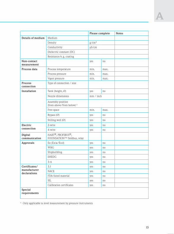
A 2. Checklist
You should be familiar with all of the requirements of
your application for the selection of the right instru-
ment. The checklist on page 9 provides an overview
of relevant process data and will help you to take the
same into consideration. If we have not included all of
the details, please supplement the list by your criteria.
The checklist is required both for the selection of the
measuring principle and the selection of the instru-
ment.
The following table compares the individual measuring
methods and is supposed to assist in a first preselection.
Selection guide Radar Guided
radar
Ultrasonics Hydrostatic Capaci-
tance
Condensate O + O + +
Foam formation O + O + O
Conductivity 1…100μs/cm + + + + O
Changing media (density) + + + – +
Low DC O O + + O
Viscosity + O + + O
Build-up formation + O + O O
Small tank (blocking distance) O O O + +
Hygienic application (cleanability) + + + + +
Pressurization + + O + +
Simple maintenance (disassembly) + O + O O
Independent of installation site O + O O +
Unaffected by obstacles O + O + +
Small tank (fast level change) O O O + +
Vapor pressure
> 50mbar / +20°C, > 0.73psi / +68°F)
+ + O + +
CIP/SIP temperature cycles + + + + +
+ = recommended
O = restricted (observe limits)
– = not recommended
TIP
Copy this checklist and complete it to have all relevant
data at your disposal in the selection process.
Radiometry is not included in detail in the
following chapters. For specific information
please contact our sales team.
1313
A
Please complete Notes
Details of medium Medium
Density g/cm3
Conductivity μS/cm
Dielectric constant (DC)
Resistance/e. g. coating
Non-contact
measurement
yes no
Process data Process temperature min. max.
Process pressure min. max.
Vapor pressure min. max.
Process
connection
Type of connection / size
Installation Tank (height, Ø) yes no
Nozzle dimensions mm / inch
Assembly position
(from above/from below) 1)
Free space min. max.
Bypass (Ø) yes no
Stilling well (Ø) yes no
Electric
connection
2-wire yes no
4-wire yes no
Digital
communication
HART®, PROFIBUS®,
FOUNDATION™ fieldbus, relay
Approvals Ex (Ex ia/Ex d) yes no
WHG yes no
Shipbuilding yes no
EHEDG yes no
3-A yes no
Certificates/
manufacturer
declarations
3.1 yes no
NACE yes no
FDA-listed material yes no
SIL yes no
Calibration certificates yes no
Special
requirements
1) Only applicable to level measurement by pressure instruments

1414
B
Ple
Guided
3. Selection of the measuring principle according to the application
Non-contact Con
Radar
Micropilot
Ultrasonics
Prosonic S/M/T
Advantages • For highly viscous media
• High resistance
• Universally usable (free adjustable meas-
uring range)
• High resistance
• Self-cleaning effect of sensors
• Integrated alarm/point level relay
• Free adjustable measuring range
• Una
• No
• Ta
• N
• D
• Coa
Technical data
• Connection
• Accuracy
• Process temperature
• Process pressure
• Process connection
• Maximum measuring
range
2-wire (HART®, PA, FF), 4-wire HART®
±2mm/±0.08"–196…+450°C/–321…+842°F
–1…+160bar/–14.5…+2,320psi
Threads, flanges (DIN, ANSI, JIS),
hygienic connections
70m/229ft
2-/4-wire (HART®, DP, PA, FF)
±2mm/±0.08" +0.17% of the distance
–40…+105°C/–40…+221°F
–0.3…+3bar/–4.4…+44psi
Threads, Tri-Clamp, flanges (DIN, ANSI, JIS)
20m/65ft
2-wire
±2mm
–196…
–1…+
Threa
hygien
10m/3
6m/20
Application limits • Strong formation
of foam
• Many obstacles
• Low DC value
(< 1.4)
guided radar,
hydrostatics
guided radar,
capacitance,
hydrostatics
hydrostatics
• Strong formation
of foam
• Vapor pressure
• Many obstacles
guided radar,
hydrostatics
radar, guided radar,
capacitance
guided radar,
capacitance,
hydrostatics
• Stro
form
high
crys
med
• Low
(< 1
FMU90
FDU9x
(separated) (compact)
Please note:
Radar continued on Page 34
Please note:
Ultrasonics continued on Page 56
FMU4x
FMU30FMR5x

1515
B
Please note:
Guided radar continued on Page 50
Please note:
Hydrostatics continued on Page 66
Please note:
Capacitance continued on Page 62
on
Contact
Our proposal
Guided radar
Levelflex
Hydrostatics
Deltapilot M
Capacitance
Liquicap M
• Unaffected by changing media
• No impairment by the installations of
• Tank baffles
• Nozzle dimensions
• Double reflection
• Coaxial probe
• Unaffected by foam
• Unaffected by installation situation
• Unaffected by DC value
• Ground tube probe
• Unaffected by nozzle dimensions
and tank obstacles
• Calibration not required in
conductive liquids
• No blocking distance
2-wire (HART®, PA, FF), 4-wire HART®
±2mm/±0.08"
–196…+450°C/–321…+842°F
–1…+400bar/–14.5…+5,800psi
Threads, flanges (DIN, ANSI, JIS),
hygienic connections
10m/33ft (rod), 45m/148ft (rope),
6m/20ft (coax), longer upon request
2-wire (HART®, PA, FF)
±0.1%, (typ. 3…10mm/0.12"…0.4")
–10…+80°C/+14…+176°F
Ambient pressure
Threads, flanges (DIN, ANSI, JIS),
hygienic connections
Typically up to 100m/328ft
(10bar/145psi)
2-wire (HART®)
±1.0%
–80…+200°C/–112…+392°F
–1…+100bar/–14.5…+1,450psi
Threads, flanges (DIN, ANSI, JIS),
hygienic connections
4m/13ft (rod), 10m/32ft (rope)
ar,
• Strong build-up
formation (e. g.
high viscosity,
crystallizing
media, etc.)
• Low DC value
(< 1.4)
radar,
ultrasonics
hydrostatics
• Density change
• Strong build-up
formation
guided radar,
radar,
ultrasonics
radar,
ultrasonics
• Changing, non-
conductive media
or conductivity
between
1…100μs/cm
• Strong, conductive
build-up formation
guided radar,
radar,
ultrasonics
radar,
ultrasonics
FMI5xFMP5x
(coax)FMB5x
Horizontal cylindrical storage tank
• Calm surface (e. g. bottom filling, filling via
immersion tube or rare free filling from above)
• Accuracy 3…10mm/0.12…0.4"
• Free space measurement (without stilling well,
top mounted)
• Tank diameter up to 3m/9.8ft
• Changing media
• Installation from above
≤ 3
m/9.8
ft
x
0
xF
Hori
zonta
l cyli
nd.
stora
ge
tan
k

1616
B
Ple
Guided
Non-contact Con
Our proposal
Radar
Micropilot
Ultrasonics
Prosonic S/M/T
Advantages • Non-contact and unaffected by head
pressures
• Universally useable due to
• Flexible measuring range
• Changing, highly viscous or
aggressive media (100 % PTFE)
• High resistance
• Self-cleaning effect of sensors
• Integrated alarm/point level relay
• Una
tan
Technical data
• Connection
• Accuracy
• Process temperature
• Process pressure
• Process connection
• Maximum measuring
range
2-wire (HART®, PA, FF), 4-wire HART®
±2mm/±0.08"
–196…+450°C/–321…+842°F
–1…+160bar/–14.5…+2,320psi
Threads, flanges (DIN, ANSI, JIS),
hygienic connections
70m/229ft
2-/4-wire (HART®, DP, PA, FF)
±2mm/±0.08" +0.17% of the distance
–40…+105°C/–40…+221°F
–0.3…+3bar/–4.4…+44psi
Threads, Tri-Clamp, flanges (DIN, ANSI, JIS)
20m/65ft
2-wir
±2mm
–196…
–1…+
Threa
hygien
10m/
6m/2
Application limits • Strong formation
of foam
• Many obstacles
• Low DC value
(< 1.4)
guided radar,
hydrostatics
guided radar,
capacitance,
hydrostatics
hydrostatics
• Strong formation
of foam
• Vapor pressure
> 50mbar/
0.73psi
(20°C/+68°F)
• Many obstacles
guided radar,
hydrostatics
radar, guided radar,
capacitance
guided radar, capaci-
tance, hydrostatics
• Stro
form
hig
cry
med
• Low
(< 1
3. Selection of the measuring principle according to the application
FMU90
FDU9x
Please note:
Radar continued on Page 34
Please note:
Ultrasonics continued on Page 56
(separated) (compact)
FMU4x
FMU30FMR5x

1717
B
Please note:
Guided radar continued on Page 50
Please note:
Hydrostatics continued on Page 66
Please note:
Capacitance continued on Page 62
Contact
Our proposal
Guided radar
Levelflex
Hydrostatics
Deltapilot, Cerabar,
Deltabar
Capacitance
Liquicap M
• Unaffected by nozzle dimensions and
tank obstacles
• Tried and tested technology providing
easy engineering and commissioning
• Unaffected by
• DC values
• Tank baffles
• Foam
• Unaffected by nozzle dimensions
and tank obstacles
• Calibration not required in
conductive liquids
• No blocking distance
S)
2-wire (HART®, PA, FF), 4-wire HART®
±2mm/±0.08"
–196…+450°C/–321…+842°F
–1…+400bar/–14.5…+5,800psi
Threads, flanges (DIN, ANSI, JIS),
hygienic connections
10m/33ft (rod), 45m/148ft (rope),
6m/20ft (coax), longer upon request
2-wire (HART®, PA, FF)
±0.075% of the set span
–70…+400°C/–94…+752°F
420bar/6,092psi
Threads, flanges (DIN, ANSI, JIS),
hygienic connections
Typically up to 100m/328ft
(10bar/145psi)
2-wire (HART®)
±1.0%
–80…+200°C/–112…+392°F
–1…+100bar/–14.5…+1,450psi
Threads, flanges (DIN, ANSI, JIS),
hygienic connections
4m/13ft (rod), 10m/32ft (rope)
ar,
aci-
cs
• Strong build-up
formation (e. g.
high viscosity,
crystallizing
media, etc.)
• Low DC value
(< 1.4)
radar,
ultrasonics
hydrostatics
• Density change
• Strong build-up
formation
guided radar,
radar,
ultrasonics
radar,
ultrasonics
• Changing, non-
conductive media
or conductivity
between
1…100μs/cm
• Strong, conductive
build-up formation
guided
radar, radar,
ultrasonics
radar,
ultrasonics
on
FMP5x
FMI5x
Vertical storage tank
• Calm surface (e. g. bottom filling, filling via
immersion tube or rare free filling from above)
• Accuracy 3…10mm/0.12…0.4"
• Free space measurement
(without stilling well/bypass)
x
0
PMD5x,
PMD7x,
FMD7x
PMC/PMP5x
FMB5x,
FMB7x
FMD72
Vert
ical
stora
ge
tan
k

1818
B
Ple
Hydros
Non-contact Con
Our proposal
Radar
Micropilot
Ultrasonics
Prosonic S/M
Advantages • Non-contact and unaffected by head
pressures
• Universally useable due to
• Flexible measuring range
• Changing, highly viscous or
aggressive media (100 % PTFE)
• High resistance
• Self-cleaning effect of sensors
• Integrated alarm/point level relay
• Fast measuring frequency (4-wire)
• Una
• Una
• Una
• Elec
Technical data
• Connection
• Accuracy
• Process temperature
• Process pressure
• Process connection
• Maximum measuring
range
2-wire (HART®, PA, FF), 4-wire HART®
±2mm/±0.08"
–196…+450°C/–321…+842°F
–1…+160bar/–14.5…+2,320psi
Threads, flanges (DIN, ANSI, JIS),
hygienic connections
70m/229ft
2-/4-wire (HART®, DP, PA, FF)
±2mm/±0.08" +0.17% of the distance
–40…+105°C/–40…+221°F
–0.3…+3bar/–4.4…+44psi
Threads, Tri-Clamp, flanges (DIN, ANSI, JIS)
20m/65ft
2-wire
±0.075
–70…+
420ba
Thread
hygien
Typica
(10bar
Application limits • Strong formation
of foam
• Many obstacles
in the radar
beam
• Low DC value
(< 1.4)
guided radar,
hydrostatics
guided radar,
capacitance,
hydrostatics
hydrostatics
• Strong formation
of foam
• Vapor pressure
• Many obstacles
guided radar,
hydrostatics
radar, guided radar,
capacitance
guided radar,
capacitance,
hydrostatics
• Den
chan
• Stro
up f
• Rati
pres
hyd
pres
max
elec
3. Selection of the measuring principle according to the application
FMU90
FMU4x
FDU9x
(separated) (compact)
Please note:
Radar continued on Page 34
Please note:
Ultrasonics continued on Page 56
FMR5x

1919
B
Please note:
Guided radar continued on Page 50
Please note:
Hydrostatics continued on Page 66
Please note:
Capacitance continued on Page 62
Contact
Hydrostatics
Cerabar, Deltabar
Guided radar
Levelflex
Capacitance
Liquicap M
• Unaffected by foam
• Unaffected by installation situation
• Unaffected by DC value
• Electronic dp
• Unaffected by nozzle dimensions and
tank obstacles
• Unaffected by agitated surfaces
• For small tanks with fast filling and
discharging operations
• Unaffected by nozzle dimensions and
tank obstacles
• No blocking distance
2-wire (HART®, PA, FF)
±0.075% of the set span
–70…+400°C/–94…+752°F
420bar/6,092psi
Threads, flanges (DIN, ANSI, JIS),
hygienic connections
Typically up to 100 m/328 ft
(10bar/145psi)
2-wire (HART®, PA, FF), 4-wire HART®
±2mm/±0.08"
–196…+450°C/–321…+842°F
–1…+400bar/–14.5…+5,800psi
Threads, flanges (DIN, ANSI, JIS),
hygienic connections
10m/33ft (rod), 45m/148ft (rope),
6m/20ft (coax), longer upon request
2-wire (HART®)
±1.0%
–80…+200°C/–112…+392°F
–1…+100bar/–14.5…+1,450psi
Threads, flanges (DIN, ANSI, JIS),
hygienic connections
4m/13ft (rod), 10m/32ft (rope)
ar,
• Density
change
• Strong build-
up formation
• Ratio head-
pressure to
hydrostatic
pressure
max. 6:1 for
electronic dp
guided radar,
radar,
ultrasonics
radar,
ultrasonics,
bubble system
radar, guided
radar, dp
• Strong lateral load
• Strong build-up
formation
(e. g. high viscosity,
crystallizing media,
etc.)
• DC starting at 1.4
radar,
ultrasonics,
hydrostatics
radar,
ultrasonics
hydrostatics
• Changing, non-
conductive media
or conductivity
between
1…100μs/cm
• Strong, conductive
build-up formation
• Strong lateral load
guided
radar, radar,
ultrasonics
radar,
ultrasonics
radar,
ultrasonics,
hydrostatics
on
FMP5x FMI5x
Buffer tank
• Agitated surface (e. g. permanent free filling from
above, mixing jets, slowly turning mixer, lateral
installation)
• Free space measurement (without stilling well)
• Foam spots, islands
• Pressurized
• Fast temperature changes (cleaning)
FM 5xPMD5x, PMD7x, FMD7x
FMD72
(electronic dp)
Cerabar, D
Bu
ffer
tan
k

2020
BCon
Adva
Techn
• Con
• Acc
• Pro
tem
• Pro
• Pro
con
• Ma
mea
Appli
3. Selection of the measuring principle according to the application
Notes

2121
BContact
Our proposal
Capacitance
Liquicap M
Guided radar
Levelflex
Hydrostatics
Deltapilot, Deltabar, Cerabar
Advantages • Fastest response times in
filling and discharging
operations
• Maximum tank exploitation
– no blocking distance
• Unaffected by nozzle
dimensions and tank baffles
• Unaffected by nozzle dimensions
and tank obstacles
• Unaffected by product properties
(conductivity, density)
• Electronic dp
• Unaffected by foam
• Unaffected by installation
situation
• Unaffected by DC value
• Fast response times
• Unaffected by
ambient temperatures
Technical data
• Connection
• Accuracy
• Process
temperature
• Process pressure
• Process
connection
• Maximum
measuring range
2-wire (HART®)
±1.0%
–80…+200°C/–112…+392°F
–1…+100bar/–14.5…+1,450psi
Threads, flanges (DIN, ANSI,
JIS), hygienic connections
4m/13ft (rod),
10m/32ft (rope)
2-wire (HART®, PA, FF), 4-wire
HART®
±2mm/±0.08"
–196…+450°C/–321…+842°F
–1…+400bar/–14.5…+5,800psi
Threads, flanges (DIN, ANSI, JIS),
hygienic connections
10m/33ft (rod), 45m/148ft (rope),
6m/20ft (coax), longer upon
request
2-wire (HART®, PA, FF)
±0.075% of the set span
–40…+150°C/–40…+302°F
40bar/580psi
Threads, flanges (DIN, ANSI,
JIS), hygienic connections
Typically up to 100m/328ft
(10bar/145psi)
Application limits • Changing,
non-
conductive
media or
conductivity
between
1…100μs/cm
hydro-
statics
• Extremely fast
filling and dis-
charging operations
(response times
< 0.7sec)
• Highly accurate
measurements
in the lower and
upper area
• DC starting at 1.4
capaci-
tance
capaci-
tance
hydro-
statics
• Density
change
• Electronic
dp-ratio
head
pressure to
hydrostatic
pressure
max. 6 : 1
capacitance
capacitance,
guided
radar
FMI5x
Please note: Guided radar
continued on Page 50
Please note: Hydrostatics
continued on Page 66
Please note: Capacitance
continued on Page 62
on
Recipient tank (e. g. bottling facilities)
• Pressurized
• Fast temperature changes (cleaning)
• Fast filling and discharging operations
• Tank < 1m/3.2ft in height
• Strongly foaming surface
≤ 1
m/3.2
ft
FMP5xFM 5x
2 x FMB50/
FMB70
FMD72
2 x PMC/PMP5x,
2 x PMC/PMP7x
Reci
pie
nt
tan
k
(e. g
. bott
lin
g fa
cili
ties)

2222
B
Pl
Hydro
Non-contact Con
Our proposal
Radar
Micropilot
Ultrasonics
Prosonic S/M
Advantages • Non-contact and unaffected by head
pressures
• Universally useable due to
• Flexible measuring range
• Changing, highly viscous or
aggressive media (100 % PTFE)
• High resistance
• Self-cleaning effect of sensors
• Integrated alarm/point level relay
• Fast measuring frequency (4-wire)
• Tri
an
• Un
• D
• T
• F
• S
Technical data
• Connection
• Accuracy
• Process temperature
• Process pressure
• Process connection
• Maximum measuring
range
2-wire (HART®, PA, FF), 4-wire HART®
±2mm/±0.08"
–196…+450°C/–321…+842°F
–1…+160bar/–14.5…+2,320psi
Threads, flanges (DIN, ANSI, JIS),
hygienic connections
70m/229ft
2-/4-wire (HART®, DP, PA, FF)
±2mm/±0.08" +0.17% of the distance
–40…+105°C/–40…+221°F
–0.3…+3bar/–4.4…+44psi
Threads, Tri-Clamp, flanges (DIN, ANSI, JIS)
20m/65ft
2-wi
±0.07
–70…
420b
Thre
hygie
40m/
Application limits • Strong formation of
foam
• Many obstacles
• Low DC value (< 1.4)
• Extreme turbulences
hydrostatics
• Strong formation of
foam
• Vapor pressure
• Many obstacles
• Fast temperature
changes
• Strong turbulences
hydrostatics
radar
hydrostatics
radar
hydrostatics
• De
• Str
for
3. Selection of the measuring principle according to the application
FMU90
FMU4x
FDU9x
(separated) (compact)
Please note:
Radar continued on Page 34
Please note:
Ultrasonics continued on Page 56
FMR5x
FM
(ele

2323
B
Please note:
Hydrostatics continued on Page 66
Contact
Our proposal
Hydrostatics
Deltabar
• Tried and tested technology providing easy engineering
and commissioning
• Unaffected by
• DC values
• Tank baffles
• Foam
• Strongly fluctuating ambient temperatures
S)
2-wire (HART®, PA, FF)
±0.075% of the set span
–70…+400°C/–94…+752°F
420bar/6,090psi
Threads, flanges (DIN, ANSI, JIS),
hygienic connections
40m/131ft (4bar/58psi)
s
s
s
• Density change
• Strong build-up
formation
radar, ultrasonics
radar, ultrasonics, bubble
system
on
Process tank with agitator
• Agitated surface
• Single-stage agitator (< 60 RPM)
• Pressurized
• Free space measurement (without stilling well/bypass)
• Foam formation is possible depending on the application
PMD5x,
PMD7x,
FMD7x
FMD72
(electronic dp)
Pro
cess
tan
kw
ith
agit
ator

2424
B
Pl
Guide
Non-contact Con
Our proposal
Radar
Micropilot
Ultrasonic
Prosonic S/M
Advantages • Non-contact and unaffected by
head pressures
• Universally useable due to flexible
measuring range
• Installation for stilling wells > 4m
• Also with ball valve
• High resistance
• Self-cleaning effect of sensors
• Integrated alarm/point level relay
• Unaffected by stilling well material
• Un
• Di
Technical data
• Connection
• Accuracy
• Process temperature
• Process pressure
• Process connection
• Maximum measuring
range
2-wire (HART®, PA, FF), 4-wire HART®
±2mm/±0.08"
–196…+450°C/–321…+842°F
–1…+160bar/–14.5…+2,320psi
Threads, flanges (DIN, ANSI, JIS),
hygienic connections
70m/229ft
2-/4-wire (HART®, DP, PA, FF)
±2mm/±0.08" +0.17% of the distance
–40…+105°C/–40…+221°F
–0.3…+3bar/–4.4…+44psi
Threads, Tri-Clamp, flanges (DIN, ANSI, JIS)
20m/65ft
2-wi
±2m
–196
–1…+
Thre
hygie
10m/
longe
Application limits • Large changes in the
stilling well cross
section
• Arrangement, size of
equalizing openings
• Plastic stilling wells
• DC starting at 1.4
guided radar,
capacitance
guided radar,
capacitance
ultrasonics,
guided radar
float
• Vapor pressure radar • Co
pro
we
• Hi
pro
(>
• Ma
len
• DC
3. Selection of the measuring principle according to the application
FMU90
FMU4x
FDU9x
(separated) (compact)
Please note:
Radar continued on Page 34
Please note:
Ultrasonics continued on Page 56
FMR5x

2525
B
FMI5xFMP5x
Please note:
Guided radar continued on Page 50
Please note:
Capacitance continued on Page 62
Contact
Our proposal
Guided radar
Levelflex
Capacitance
Liquicap M
• Unaffected by the stilling well geometry
• Divisible rod probe
• Unaffected by the stilling well
geometry
, JIS)
2-wire (HART®, PA, FF), 4-wire HART®
±2mm/±0.08"
–196…+450°C/–321…+842°F
–1…+400bar/–14.5…+5,800psi
Threads, flanges (DIN, ANSI, JIS),
hygienic connections
10m/33ft (rod), 45m/148ft (rope),
longer upon request
2-wire (HART®)
±1.0 %
–80…+200°C/–112…+392°F
–1…+100bar/–14.5…+1,450psi
Threads, flanges (DIN, ANSI, JIS),
hygienic connections
4m/13ft (rod), 10m/32ft (rope)
• Contact between
probe and stilling
well
• Highly viscous
products
(> 1000 cst)
• Max. stilling well
length 10 m/33 ft
• DC starting at 1.4
radar,
ultrasonics
radar,
ultrasonics
float
• Changing, non-
conductive media
or conductivity
between
1…100μs/cm
guided radar,
radar,
ultrasonics
tion
Stilling well
• Measurement in metal pipes (installed in the tank)
e. g. immersion tube
• Nominal width typ. DN 40…DN 150/1.5"…6"
x
FM
Sti
llin
g w
ell

2626
B
Ple
Guided
3. Selection of the measuring principle according to the application
Non-contact Con
Radar
Micropilot
Advantages • Measurement with ball valve possible
• For highly viscous media (100% PTFE possible)
• Universally usable (free adjustable measuring range)
• No
• Un
• Saf
up
Technical data
• Connection
• Accuracy
• Process temperature
• Process pressure
• Process connection
• Maximum measuring
range
2-wire (HART®, PA, FF), 4-wire HART®
±2mm/±0.08"
–196…+450°C/–321…+842°F
–1…+160bar/–14.5…+2,320psi
Threads, flanges (DIN, ANSI, JIS),
hygienic connections
70m/229ft
2-wir
±2mm
–196
–1…+
Threa
hygie
10m/
longe
Application limits • Strong formation
of foam
• Many obstacles
• Low DC value
(< 1.4)
guided radar,
hydrostatics
guided radar, capacitance,
hydrostatics
hydrostatics
• Str
for
hig
cry
me
• Low
(<
Please note:
Radar continued on Page 34
FMR5x

2727
B
Please note:
Guided radar continued on Page 50
Please note:
Capacitance continued on Page 62
tion
Contact
Our proposal
Guided radar
Levelflex
Capacitance
Liquicap M
• No impairment by bypass connections
• Unaffected by changing media
• Safe operation in case of filling via
upper connection (“coaxial probe”)
• For small tanks with fast filling and
discharging operations
• Unaffected by nozzle dimensions and
tank obstacles
• No blocking distance
2-wire (HART®, PA, FF), 4-wire HART®
±2mm/±0.08"
–196…+450°C/–321…+842°F
–1…+400bar/–14.5…+5,800psi
Threads, flanges (DIN, ANSI, JIS),
hygienic connections
10m/33ft (rod), 45m/148ft (rope),
longer upon request
2-wire (HART®)
±1.0 %
–80…+200°C/–112…+392°F
–1…+100bar/–14.5…+1,450psi
Threads, flanges (DIN, ANSI, JIS),
hygienic connections
4m/13ft (rod), 10m/32ft (rope)
• Strong build-up
formation (e. g.
high viscosity,
crystallizing
media, etc.)
• Low DC value
(< 1.4)
radar
hydrostatics
• Changing, non-
conductive media
or conductivity
between
1…100μs/cm
• Strong, conductive
build-up formation
guided radar,
radar
radar,
hydrostatics
FMI5xFMP5x
Bypass
• Measurement in metal pipes (installed outside the tank)
• Replacement of displacer/float vessels, compensation vessels
• Nominal width typ. DN 40…DN 150/1.5"…6"
F
Bypass

2828
B
FM
Ple
Hydros
3. Selection of the measuring principle according to the application
Non-contact Con
Our proposal
Ultrasonics
Prosonic S/M
Radar
Micropilot
Advantages • Overspill-protected, heated sensors with self-
cleaning effect
• Universal use due to flexible measuring range
• Operation and display at easily accessible mounting
locations possible incl. integrated point level relay
and integrated control functions
• Universally usable (free adjustable
measuring range)
• Unaffected by temperature layers
• Free of maintenance
• Trie
eng
• Una
situ
• Op
acc
Technical data
• Connection
• Accuracy
• Process temperature
• Process pressure
• Process connection
• Maximum measuring
range
2-/4-wire (HART®, DP, PA, FF)
±2mm/±0.08" +0.17% of the distance
–40…+105°C/–40…+221°F
–0.3…+3bar/–4.4…+44psi
Threads, Tri-Clamp, flanges (DIN, ANSI, JIS)
20m/65ft
2-wire (HART®, PA, FF), 4-wire HART®
±2mm/±0.08"
–196…+450°C/–321…+842°F
–1…+160bar/–14.5…+2,320psi
Threads, flanges (DIN, ANSI, JIS),
hygienic connections
70m/229ft
2-wir
±0.1%
–10…
Ambie
Moun
200m
Application limits • Strong formation of
foam
• Many obstacles
hydrostatics
• Strong formation
of foam
• Many obstacles
hydrostatics
• Ris
form
pol
FMU90
FMU4x
FDU9x
(separated)(compact)
Please note:
Radar continued on Page 34
Please note:
Ultrasonics continued on Page 56
FMR5x
2929
B
FMB53
FMX21/
FMX167 FMI5x
Please note:
Capacitance continued on Page 62
Please note:
Hydrostatics continued on Page 66
tion
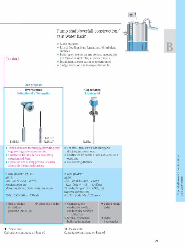
Contact
Our proposal
Hydrostatics
Deltapilot M / Waterpilot
Capacitance
Liquicap M
le
s
• Tried and tested technology, providing easy
engineering and commissioning
• Unaffected by tank baffles, mounting
situation and foam
• Operation and display possible at easily
accessible mounting locations
• For small tanks with fast filling and
discharging operations
• Unaffected by nozzle dimensions and tank
obstacles
• No blocking distance
ART® 2-wire (HART®, PA, FF)
±0.1%
–10…+80°C/+14…+176°F
Ambient pressure
Mounting clamp, cable mounting screw
200m/656ft (20bar/290psi)
2-wire (HART®)
±1.0%
–80…+200°C/–112…+392°F
–1…+100bar/–14.5…+1,450psi
Threads, flanges (DIN, ANSI, JIS),
hygienic connections
4m/13ft (rod), 10m/32ft (rope)
tatics
• Risk of sludge
formation/
pollution (build-up)
ultrasonics, radar • Changing, non-
conductive media or
conductivity between
1…100μs/cm
• Strong, conductive
build-up formation
guided radar,
radar
radar,
hydrostatics
Pump shaft/overfall construction/
rain water basin
• Many obstacles
• Risk of flooding, foam formation and turbulent
surfaces
• Build-up on the sensor and contacting obstacles
(ice formation in winter, suspended solids)
• Installation at open basins or underground
• Sludge formation due to suspended solids
Pu
mp s
haft
/overf
all
con
stru
ctio
n/
rain
wat
er
basi
n

3030
B
FM
F
Ple
Hydros
3. Selection of the measuring principle according to the application
Non-contact Con
Our proposal
Ultrasonics
Prosonic S/M
Radar
Micropilot
Advantages • No flow impairment
• Overspill-protected, heated sensors with self-
cleaning effect
• Operation and display at easily accessible
mounting locations possible incl. integrated
point level relay and preprogrammed flow
curves
• Universally usable (free adjustable
measuring range)
• Unaffected by temperature layers
• Free of maintenance
• Una
• Una
• Sim
is n
Technical data
• Connection
• Accuracy
• Process temperature
• Process pressure
• Process connection
• Maximum measuring
range
2-/4-wire (HART®, DP, PA, FF)
±2mm/±0.08" +0.17% of the distance
–40…+105°C/–40…+221°F
–0.3…+3bar/–4.4…+44psi
Threads, Tri-Clamp, flanges (DIN, ANSI, JIS)
20m/65ft
2-wire (HART®, PA, FF), 4-wire HART®
±2mm/±0.08"
–196…+450°C/–321…+842°F
–1…+160bar/–14.5…+2,320psi
Threads, flanges (DIN, ANSI, JIS),
hygienic connections
70m/229ft
2-wir
±0.1%
–10…
Ambie
Moun
200m
Application limits • Strong formation of
foam
• Many obstacles
hydrostatics• Strong formation of
foam
• Many obstacles
hydrostatics• Risk
poll
• Inst
wat
FMU90
FMU4x
FDU9x
(separated) (compact)
Please note:
Radar continued on Page 34
Please note:
Ultrasonics continued on Page 56
FMR5x

31
FMB53
FMX21/
FMX167
Please note:
Hydrostatics continued on Page 66
tion
Contact
Hydrostatics
Waterpilot / Deltapilot M
• Unaffected by obstacles / installation situation
• Unaffected by foam formation
• Simple commissioning, calibration
is not required
® 2-wire (HART®, PA, FF)
±0.1%
–10…+80°C/+14…+176°F
Ambient pressure
Mounting clamp, cable mounting screw
200m/656ft (20bar/290psi)
tatics• Risk of sludge accumulation /
pollution (build-up formation)
• Installation not in flowing
water
ultrasonics,
radar
ultrasonics,
radar
Channel measurement
(free flowing)
• Risk of flooding, foam formation
• Obstacles
• Condensate formation (icing in winter)
on sensor and instrument
• Build-up on the sensor and contacting obstacles
(ice formation in winter, suspended solids)
• Installation at open basins or underground
Ch
an
nel
measu
rem
ent
(fre
e fl
ow
ing)

3232
B
3. Selection of the measuring principle according to the application
Contact
Guided radar
Levelflex
Multiparameter
Levelflex
Advantages • Simultaneous acquisition of interface layer and
total level
• Not affected by the density of the medium
• No wet calibration required
• Direct replacement of displacers in existing
displacer chambers
• Probes can be shortened (rod)
• Simultaneous acquisition of interface
layer and overall level, also in case of
emulsions
• Precise and reliable measurement
• Independent of medium density
• Wet calibration not required
• PTFE-coated probe
• Tr
• No
• No
• Un
• Ide
• Ex
Technical data
• Connection
• Accuracy
• Process temperature
• Process pressure
• Process connection
• Maximum measuring
range
2-wire (HART®/PA), 4-wire
±2mm/±0.08" (overall level);
±10mm/±0.39" (interface level)
–196…+450°C/–321…+842°F
–1…+400bar/–14.5…+5,800psi
Threads, flanges (DIN, ANSI, JIS), hygiene
connections
6m/20ft (coax), 10m/33ft (rope/rod),
longer upon request
2-wire (HART®/PA), 4-wire
±2mm/±0.08" (overall level);
±10mm/±0.39" (interface level)
–50…+200°C/–58…+392°F
–1…+40bar/–14.5…+580psi
Threads, flanges (DIN, ANSI, JIS), hygiene
connections
6m/20ft (coax), 10m/33ft (rope),
4m/13ft (rod), longer upon request
2-wi
±1%
–80…
–1…+
Thre
4m/
Application limits • Dielectric constant (DC value) of the upper
medium must be determined
• DC value changes of the upper medium
influence accuracy
• DC value of the upper medium may be max. 10
• Difference of the DCs between the two media
must be >10
• For interface measurement, the thickness of
the upper phase must be min. 60mm/2.36"
• Emulsion layers up to max. 50mm/1.97"
allowable
• Dielectric constant (DC value) of the
upper medium must be determined
• DC value changes of the upper medium
affect the accuracy
• DC value of the upper medium may be
max. 10
• DC value difference between both media
must be >10
• For interface layer measurement, the
thickness of the upper phase must be
minimum 60mm/2.36"
• Di
th
Th
• Ac
on
• Th
of
• Th
th
• Th
Please note:
Guided radar continued on Page 50
Cap
FMP55FMP51/52/54
1 1 2 1

3333
B
Interface measurement
Interface liquid/liquid
With emulsion layer
Multiphase measurement
tion
Non-contact
Capacitance
Liquicap
Radiometrics
Gammapilot
e
of
• Tried and tested instrumentation
• No wet calibration required
• Not affected by the density of the medium
• Unproblematic use in emulsion layers
• Ideal for very small measuring ranges
• Extremely fast response time
• Non-invasive and maintenance-free
measuring method
• Unaffected by pressure and temperature
• Only slight influence by build-up
• Unproblematic use in emulsion layers
• Solutions for multiphase measurements
using several detectors
iene
2-wire (HART®)
±1%
–80…+200°C/–112…+392°F
–1…+100bar/–14.5…+1,450psi
Threads, flanges (DIN, ANSI, JIS), hygiene connections
4m/13ft (rod), 10m/32ft (rope)
4-wire (HART®, PA, FF)
±1% of measuring distance
Independent (non-invasive)
Independent (non-invasive)
Independent (non-invasive)
Adaptable to application
e
ium
be
media
e
e
• Difference of the dielectric constant (DC value) between
the two media must be >10.
The upper medium may not be conductive
• Accuracy impairment in case of nonconductive build-up
on the probe
• The smaller the vessel the higher the influence
of DC changes in the upper medium
• The bigger the quotient DC(below) / DC(above)
the better the accuracy
• The total level is not measured
• Medium density changes influence the
accuracy
• The overall level is not measured (possible with a
further source and detector)
• Calibration with the medium is required
• Radiation Protection Law
Please note:
Capacitance continued on Page 62
1 2 3
FMG60FMI51/52
1 2 1 2 3
Recommendation
Inte
rfac
e m
easu
rem
ent

3434
C
4. Instrument selection within the measuring principle
Required application data
• Pressure and temperature
• Dielectric constant of the medium
(DC)/media group
• Required material compatibility
• Nozzle diameter/nozzle height
• Measuring range
• Required accuracy
• For stilling well/bypass:
Internal pipe diameter
Application limits for radar level
measurement
• T < –196°C/–321°F
or T > +450°C/+842°F
• p > 160bar/2320psi
• Measuring range > 70m/229ft
• Dielectric constant < 1.4
• Process connection < 1½"
Dielectric constant (DC)
The reflection properties of a medium
are determined by the dielectric
constant (DC).
The following table shows the allocation
of different DC values to media groups.
If the dielectric constant of a medium
is not known, we recommend to use
a DC value of 1.9 for sizing in order to
maintain a safe measurement.
! For reliable measurement:
Use a horn antenna whenever possible. In addition,
this should have the largest possible diameter.
Radar

3535
C
Media group DC value Examples
A 1.4…1.9 non-conductive liquids, e. g. liquified gas 1)
B 1.9…4 non-conductive liquids, e. g. benzene, oil, toluene …
C 4…10 e. g. concentrated acid, organic solvents, ester, analin, alcohol,
acetone, …
D Larger than 10 Conductive liquids, aqueous solutions, diluted acids and alkalis
• 1) Treat ammonia (NH3) like a medium of group A, i.e. measurement in stilling wells always with FMR54.
Alternatively, measurement with guided radar FMP54 respectively FMP51 including option “gastight feed-
through”
• Measuring range: Larger than 40m/131ft Micropilot with option “advanced dynamics” max. measuring
range 70m/229ft
• Accuracy: More precise than 2mm/0.08" Micropilot S (FMR5XX), or on request
Advantages
• Non-contact, maintenance-free measurement
• Unaffected by medium properties like density and
conductivity
• For high temperatures up to +400°C/+842°F
• Measurement from outside of the tank
Rad
ar
3636
C
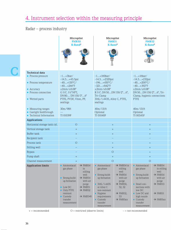
4. Instrument selection within the measuring principle
Radar – process industry
Micropilot
FMR50
K-Band2
Micropilot
FMR51
K-Band2
Micropilot
FMR52
K-Band2
Technical data
• Process pressure
• Process temperature
• Accuracy
• Process connection
• Wetted parts
• Measuring ranges
• Gastight feedthrough
• Technical Information
–1…+3bar/
–14.5…+43.5psi
–40…+130°C/
–40…+266°F
±2mm/±0.08"
G 1½", 1½" NPT,
DN 80… DN 150/3"…6"
PTFE, PVDF, Viton, PP,
sealings
30m/98ft
—
TI 01039F
–1…+160bar/
–14.5…+2320psi
–196…+450°C/
–321…+842°F
±2mm/±0.08"
R 1½", DN 50…DN 150/2"…6",
Tri-Clamp
316L/1.4435, Alloy C, PTFE,
sealings
40m/131ft
Optional
TI 01040F
–1…+16bar/
–14.5…+232psi
–40…+200°C/
–40…+392°F
±2mm/±0.08"
DN 50…DN 150/2"…6", Tri-
Clamp, hygienic connections
PTFE
40m/131ft
Optional
TI 00345F
–1…+
–14.5…
–40…
–40…
±6mm
R 1½",
hygien
316L/
sealin
20m/
Option
TI 010
Applications
Horizontal storage tank cyl. O + +
Vertical storage tank + + +
Buffer tank + + +
Recipient tank – – –
Process tank O + +
Stilling well – + +
Bypass – O +
Pump shaft + + +
Channel measurement + O O
Application limits • Ammoniacal
gas phase
• Strong build-
up formation
• Low DC
• Only PTFE
resistant
• Custody
transfer
measurement
FMR54
in
stilling
well
FMR54
with air
purge
FMR51
FMR52
FMR540
• Ammoniacal
gas phase
• Strong build-
up formation
• 316L/1.4435
or Alloy C
non-resistant
• Hygiene
requirements
• Custody
transfer
measurement
FMR54 in
stilling
well
FMR54
with air
purge
FMR50,
52, 52
FMR52,
53
FMR5xx
• Ammoniacal
gas phase
• Strong build-
up formation
• Small con-
nections with
low DC
• Low DC and
high nozzle
• Custody
transfer
measurement
FMR54
in stilling
well
FMR54
with air
purge
FMR53
FMR51
FMR5xx
• Noz
heig
> 25
/9.8
• Low
+ = recommended O = restricted (observe limits) – = not recommended

3737
C
1C-Band = 6GHz 2K-Band= 26GHz
Micropilot
FMR53
C-Band1
Micropilot
FMR54
C-Band1
Micropilot S
FMR53x
C-Band1 /
custody
transfer
Micropilot S
FMR540
K-Band2 /
custody
transfer
Tri-
tions
–1…+40bar/
–14.5…+580psi
–40…+150°C/
–40…+302°F
±6mm/0.24"
R 1½", DN 50…DN 150/2"…6",
hygienic connections
316L/1.4435, PTFE, PVDF,
sealings
20m/65ft
Optional
TI 01041F
–1…+160bar/
–14.5…+2320psi
–196…+400°C/
–321…+752°F
±6mm/0.24"
DN 80…DN 250/3"…10"
316L/1.4435, Alloy C, PTFE,
ceramics, graphite, sealings
20m/65ft
Standard
TI 01041F
–1…+40bar/
–14.5…+580psi
–40…+200°C/
–40…+392°F
±1mm/±0.04"
DN 80…DN 250/3"…10"
316Ti/1.4571, PTFE,
316L/1.4435, HNBR,
sealings
25m/82ft
Standard
TI 00344F
–1…+16bar/
–14.5…+232psi
–40…+200°C/
–40…+392°F
±1mm/±0.04"
DN 80…DN 250/3"…10"
316L/1.4435, PTFE, PEEK,
sealings
40m/131ft
Standard
TI 00412F
– – – –
O O O +
O O – –
– – – –
+ + – –
– + +* –
– O – –
– – – –
– – – –
R54
tilling
ll
R54
h air
ge
R53
R51
R5xx
• Nozzle
height
> 250 mm
/9.8"
• Low DC
FMR51,
52, 54
• Free space with
nozzle
< DN 150/6"
• Stilling well
with ball valve
• Hygiene
requirements
• 316L/1.4435
or Alloy C
non-
resistant
FMR51,
52, 53
FMR51, 52
FMR52,
53
• Free space
and many
baffles
FMR540 • Strong
condensate
or build-up
formation
• Existing
stilling
wells with
non-ideal
measuring
conditions
FMR53x
FMR532
M
cu
tr

3838
C
4. Instrument selection within the measuring principle
Measuring range in dependence on the type of tank
Process conditions and medium for Micropilot FMR50/FMR51/FMR52
Advised max. measuring range = 20m/65ft; with “advanced dynamics” = 30m/98ft
Storage tank / Channel measurement
Calm surface
(e. g. bottom filling, filling via immersion tube or
rare free filling from above)
Buffe
Agitat
(e. g. p
jets, sl
Horn/antenna diameter
FMR50 40mm/1.5" — 80mm/3" 100mm/4"
FMR51 40mm/1.5" 50mm/2" 80mm/3" 100mm/4"
FMR52 — 50mm/2" 80mm/3" —
Measuring range in m/ft
Media group
A: DC = 1.4…1.9
B: DC = 1.9…4
C: DC = 4…10
D: DC = > 10
BA C D
10/32
15/49
15/49
25/82
5/16
3/9.9
8/26
5/16
BA C D
8/26
8/26
15/49
4/13
25/82
12/39
35/110
40/131
30/99
60/197
BA C D
10/32
15/49
8/26
20/65
40/131
40/131
* *
BA C D
10/32
15/49
25/82
30/99
40/131
40/131
45/148
70/229
26
*
*
Standard:
Max. measuring
range =
40m/131ft
With application
package “Advanced
dynamics”:
Max. measuring
range = 70m/229ft
Min. measuring
range = 5m/16ft
Advised max. measuring range = 30m/98ft; with „advanced dynamics“ = 40m/131ft**
** **
**

3939
C
*
Buffer tank / Pump shafts / Open basins
Agitated surface
(e. g. permanent free filling from above, mixing
jets, slowly turning mixer, lateral installation)
40mm/1.5" — 80mm/3" 100mm/4"
40mm/1.5" 50mm/2" 80mm/3" 100mm/4"
— 50mm/2" 80mm/3" —
D
40/131
70/229
2/6.6
B C D
10/32
5/16
4/13
7.5/25
B C D
10/32
10/33
5/16
3/9.9
7.5/25
15/49
2,5
BA C D
5/16
5/16
10/32
10/32
15/4915/
49
25/85
BA C D
5/16
10/32
15/4915/
49
25/82
25/82
35/110
7.5/25
**

4040
C
4. Instrument selection within the measuring principle
Measuring range in dependence on the type of tank
Process conditions and medium for Micropilot FMR50/FMR51/FMR52
Tank with single-stage
propeller agitator
Turbulent surface,
single-stage agitator
< 60 U/min./<60 RPM
Stillin
Horn/antenna diameter
FMR50 40mm/1.5" — 80mm/3" 100mm/4"
FMR51 40mm/1.5" 50mm/2" 80mm/3" 100mm/4"
FMR52 — 50mm/2" 80mm/3" —
Measuring range in m/ft
Media group
A: DC = 1.4…1.9
B: DC = 1.9…4
C: DC = 4…10
D: DC = > 10
C D
3/9.8
5/16
2/6.6
B C D
5/16
10/32
3/9.8
2/6.6
7.5/25
B C D
15/49
5/16
8/26
12/39
2.5/8.2
B C D
4/13
8/26
5/16
15/49
10/32
20/65
Standard:
Max. measuring
range =
40m/131ft
With application
package “Advanced
dynamics”:
Max. measuring
range = 70m/229ft
Min. measuring
range = 5m/16ft

4141
C
Stilling well Bypass
40...100mm/1.5...4" —
40…100mm/1.5…4" 40…100mm/1.5…4“
50…80mm/2…3" 50…80mm/2…3"
D
0/2
0/5
A, B, C, D
20/65
C, D
20/65
For media groups A and B use
Levelflex with coax probe.

4242
C
4. Instrument selection within the measuring principle
Radar – process industry
Measuring range in dependence on the type of tank, process
conditions and medium for Micropilot FMR53/FMR54.
Storage tank 1)
Calm surface
(e. g. bottom filling, filling via immersion tube
or rare free filling from above)
Buffer tank1)
Agitated surface
(e. g. permanent free filling from above,
mixing jets)
Tank
Turbu
single
< 60 U
Horn/antenna diameter
FMR53 Rod antenna — Rod antenna —
FMR54 150mm/6"200mm/8"
250mm/10"150mm/6"
200mm/8"
250mm/10"
Measuring range in m/ft
Media group
A: DC = 1.4…1.9
B: DC = 1.9…4
C: DC = 4…10
D: DC = > 10
B
10/32
C
15/49
D
20/65
B C D
15/49
20/65
20/65
5/16
B C D
10/32
7.5/25
12.5/41
7.5/25
B C D
10/32
4/13
B
1) For media group A use stilling well (20m/65ft).2) Possible for media groups A and B, e. g. with a stilling well in the bypass.

4343
C
Tank with single-stage propeller agitator 1)
Turbulent surface,
single-stage agitator
< 60 U/min./< 60 RPM
Stilling well Bypass
Rod antenna — — — —
150mm/6"200mm/8"
250mm/10"80…250mm/3…10"
Planar antenna
150…300mm/6… 12"80…250mm/3…10" 2)
2.5/1
D
4/13
B
8/26
C
6/20
D B
8/26
C
6/20
D
10/32
A, B, C, D
20/65
20/65
C, DA, B, C, D
20/65

4444
C
4. Instrument selection within the measuring principle
Measuring range depending on the type of tank
Process conditions and medium for Micropilot S FMR530/531/532/533/540
Storage tank
Highly accurate measurement,
custody transfer
Stora
Highly
custod
Horn/antenna diameter
FMR530 150mm/6"200mm/250mm
8"/10"
FMR532
FMR533
FMR540 100mm/4" 2
Measuring range in m/ft
Media group
A: DC = 1.4…1.9
B: DC = 1.9…4
C: DC = 4…10
D: DC = > 10
B C, D
20/65
30/99
B
10/32
B C D
15/49
20/65 25/
82
Standard:
Max. measuring
range =
40m/131ft
With application
package “Advanced
dynamics”:
Max. measuring
range = 70m/229ft
Min. measuring
range = 5m/16ft

4545
C
Storage tank
Highly accurate measurement,
custody transfer
Stilling well
Highly accurate measurement,
custody transfer
150mm/6"
450mm/18"
200mm/8"
B, C, D
40/131
B, C, D
40/131
38/125
A, B, C, D

4646
C
Installation instructions radar – free space
4. Instrument selection within the measuring principle
Weather protection cover
• Always recommended for outside installation to avoid strong
temperature changes of electronics
Installation
• Not in the center
• Not above the fillstream
• Distance to wall: ~1/6 of the tank diameter, at least, however,
30cm/12" (6GHz), or 15cm/6" (26GHz)
If these conditions cannot be met: Use stilling well
• Lateral installation on request
Nozzle
• FMR51/54 horn antenna should protrude from the nozzle. Please note
the max. nozzle length, otherwise use antenna extension
• FMR50/52 note the max. nozzle length
• The inactive part of the rod antenna should be longer than the height
of the nozzle. Please contact our application consultant if this is not
possible
• Please note the information in the Technical Documentations
Measuring range
• Measurement is possible up to the tip of the antenna, on principle,
however, the end of the measuring range should not be closer than
50mm/2" to the tip of the antenna because of corrosion and build-up
formation
• The measuring range starts where the radar beam meets the tank
bottom. With dish bottoms or conical outlets, the level cannot be
detected below this point
Tank installations
• Avoid any installations like limit switches, temperature sensors, etc.
within the signal beam (see table below)
• Symmetrical installations, e. g. vacuum rings, heating coils, flow
breakers, etc. may impair measurement
Optimization options
• Size of antenna: The larger the antenna diameter the smaller the
beam angle (see table below, the less interference echoes)
• A stilling well or a Levelflex can always be used to avoid
interference
Foam of formation
• Radar pulses may be absorbed by foam
• The surface of foam can reflect. Solution: Trial measurement with
26GHz or e. g. Levelflex or hydrostatic measurement
Version
FMR 54
53
531
50
51
51
52
50
51
52
50
51 530 533 540
Antenna DN150 DN200 DN250 Rod DN40 DN50 DN80 DN100 DN150 DN200 DN250 Parabol DN100
Beam angle 23° 19° 15° 30° 23° 18° 10° 8° 23° 19° 15° 7° 4° 8°
Max. nozzle
length without
extension
[mm/"]
205/
8.1
290/
11.5
380/
15
250/
10 500/20
180/
7.1
260/
10.2
350/
13.8
200/
7.9
50/
2
430/
17

4747
C
Weather protection cover
• Always recommended for outside installation to avoid strong
temperature changes of electronics
Optimum horn size
• Select horn antenna as large as possible. In case of in-between
sizes (e. g. 95mm/3.7") use the next larger antenna and adapt it
mechanically
Ball valve
• Measurements through an open ball valve with full passage are
possible
Measuring range
• Measurement is possible up to the tip of the antenna, on principle,
however, the end of the measuring range should not be closer
than 50mm/2" to the tip of the antenna because of corrosion and
build-up formation
Recommendations for the bypass
• Metallic (without plastic or enamel coating)
• The bypass pipe must be smooth inside
(averaged roughness Ra ≤ 6.3μm)
• Constant diameter
• In transitions, caused for example by ball valves or joining of
individual pipe pieces, gaps of max. 1mm/0.04" are permitted
Installation instructions radar – bypass
540
DN100
8°
430/
17

4848
C
Installation instructions radar – stilling well
4. Instrument selection within the measuring principle
Weather protection cover
• Always recommended for outside installation to avoid strong
temperature changes of electronics
Optimum horn size
• Select horn antenna as large as possible. In case of in-between
sizes (e. g. 95mm/3.7") use the next larger antenna and adapt it
mechanically (inner diameter of stilling well diameter of horn)
Ball valve (if available)
• Measurements through an open ball valve with full passage are
possible
Measuring range
• Measurement is possible up to the tip of the antenna, on principle,
however, the end of the measuring range should not be closer
than 50mm/2" to the tip of the antenna because of corrosion and
build-up formation
Slots/holes
• As few holes/slots as possible
• Slot width or hole diameter max. 1/10 of pipe diameter
• Deburred
• Length and number do not affect the measurement
• Slots/holes 180° offset (not 90°)
Recommendations for stilling wells
• Metallic (without enamel coating, plastic upon request)
• Constant diameter
• Welding seam as even as possible and placed in the axis of the slots
• The stilling well must be smooth inside
(averaged roughness Ra ≤ 6.3μm)
• Do not weld through the wall of the pipe, the inside of the pipe
must remain smooth
• In transitions, caused for example by ball valves or joining of
individual pipe pieces, gaps of max. 1mm/0.04" are permitted

d
L50
0m
m/2
0"
4949
C
Instructions for Endress+Hauser UNI flanges in FMR54/
FMR532
• Endress+Hauser UNI flanges are designed with a pitch circle
diameter compatible with DIN, ANSI and JIS counter flanges
• UNI flanges have been designed for unpressurized operation
or atmospheric pressure (1bar/14.5psi absolute pressure). The
number of flange bolts has been partly reduced
Recommendations for stilling wells
• Metallic (without enamel coating, plastic upon request)
• Constant diameter
• Hole diameter max. 1/7 of pipe diameter and not bigger than
30mm/1.2"
• Spacing between holes min. 30cm/12"
• For FMR54/FMR532 (planar antenna) a gradual widening
(DN 150/6" to DN 200/8", DN 200/8" to DN 250/10", DN 250/10"
to DN 300/12") can even be accepted. In such cases, the upper
pipe end must have a minimum length of 500mm/20" prior to
the widening. Length L of the widening must be an additional
300mm/12" or for DN 250/10" to DN 300/12" 450mm/18"
• Larger pipe widening (e. g. DN 150/6" to DN 300/12") is possible,
if length L of the widening amounts to 450mm/18"
• Ideally, a gauge nozzle is used as upper pipe end
• Rectangular pipe widening is not permitted

5050
C
Guided radar
Media group DC Typical liquidsFMP50 FMP51
1 1.4…1.6• Liquefied gases,
e. g. N2, CO24m/13ft
6m/20ft
not with rope
2 1.6…1.9
• Liquified gas, e. g. propane
• Solvent
• Frigen / Freon
• Palm oil
12m/39ft25…30m/
82…98ft
3 1.9…2.5• Mineral oils
• Fuel12m/39ft
30…45m/
98…148ft
4 2.5…4
• Benzene, styrene, toluol
• Furan
• Naphthalene
12m/39ft 45m/148ft
5 4…7
• Chlorobenzene, chloroform
• Nitrocellulose lacquer
• Isocyan, aniline
12m/39ft 45m/148ft
6 > 7
• Aqueous solutions
• Alcohols
• Acids, lyes
12m/39ft 45m/148ft
4. Instrument selection within the measuring principle
Required application data
Level measurement
• Pressure and temperature
• Dielectric constant (DC) of the medium
• Required material compatibility
• Nozzle diameter: DN, PN, nozzle height
• Measuring range
Additional for interface measurement
• Dielectric constant (DC) of both liquids
Application limits for Levelflex
guided level radar
• T < –196°C/–321°F and T > +450°C/+842°F
• p > 400bar/5,800psi
• Measuring range > 45m/148ft (longer upon request)
• Dielectric constant < 1.4
• Process connection < ¾"
• Measuring range > 10m/32ft for
interface measurement (upon request)
Dielectric constant (DC)
The reflection properties of a medium are determined
by the dielectric constant (DC).
The following table shows the allocation of different
DC values to media groups. If the dielectric constant
of a medium is not known, we recommend to use a
DC value of 1.9 for sizing in order to maintain a safe
measurement.
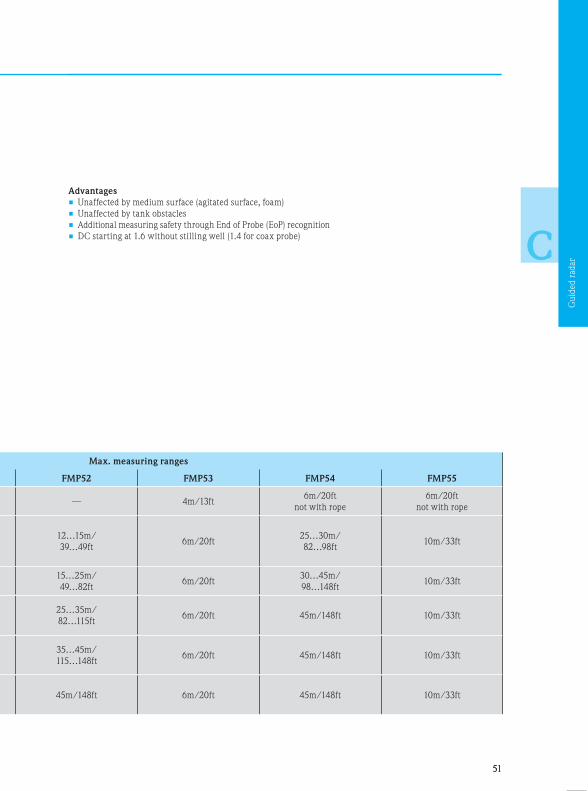
5151
C
Advantages
• Unaffected by medium surface (agitated surface, foam)
• Unaffected by tank obstacles
• Additional measuring safety through End of Probe (EoP) recognition
• DC starting at 1.6 without stilling well (1.4 for coax probe)
Max. measuring ranges
FMP52 FMP53 FMP54 FMP55
— 4m/13ft6m/20ft
not with rope
6m/20ft
not with rope
12…15m/
39…49ft6m/20ft
25…30m/
82…98ft10m/33ft
15…25m/
49…82ft6m/20ft
30…45m/
98…148ft10m/33ft
25…35m/
82…115ft6m/20ft 45m/148ft 10m/33ft
35…45m/
115…148ft6m/20ft 45m/148ft 10m/33ft
45m/148ft 6m/20ft 45m/148ft 10m/33ft
Gu
ided r
adar

5252
C
4. Instrument selection within the measuring principle
Guided radar – process industry
Levelflex
FMP50
Levelflex
FMP51
Levelflex
FMP52
Technical data
• Process pressure
• Process temperature
• Accuracy
• Process connection
• Wetted parts
• Measuring ranges
• Gastight feedthrough
• Technical Information
–1…+6bar/–14.5…+87psi
–20…+80°C/–4…+176°F
< 15m/49ft: ±2mm/0.08"
G/NPT ¾"
Rope/rod: 316L, PPS
0.3…4m/1…13ft (rod)
0.3…12m/1…39ft (rope)
—
TI 01000F
–1…+40bar/–14.5…+580psi
–40…+200°C/–40…+392°F
< 15m/49ft: ±2mm/0.08";
> 15m/49ft: ±10mm/0.4"
G/NPT ¾" and 1½",
DN 40…200/1.5"…8"
Rope: 316, rod and coax: 316L,
Alloy C (C22/2.4602), ceramics
0.3…10m/1…33ft (rod),
1…45m/3.2…148ft (rope),
0.3…6m/1…20ft (coax)
Optional
TI 01001F
–1…+40bar/–14.5…+580psi
–50…+200°C/–58…+392°F
< 15m/49ft: ±2mm/0.08";
> 15m/49ft: ±10mm/0.4"
Tri-Clamp 1½" to 3", DIN 11851,
DN 40…DN 150/1.5"…6"
PTFE, PFA
0.3…4m/1…13ft (rod)
1…45m//3.2…148ft (rope)
Optional
TI 01001F
–1…+
–20…
< 15m
Tri-Cl
SMS,
316L/
0.3…6
—
TI 010
Applications
Horizontal storage tank cyl. O +* –
Vertical storage tank + + +
Buffer tank O + +
Recipient tank + O O
Process tank – – –
Stilling well + + O
Bypass O + O
Pump shaft – – –
Channel measurement – – –
Interface measurement – +** +**
Application limits • Aggressive
media
• High
pressure/
tempera-
tures
> 80°C/
176°F;
6bar/87psi
FMP52
FMP51,
FMP54
• Aggressive
media
• Interface with
emulsion
FMP52
FMP55
• High process
temperatures
(> 150°C)
Possible
diffusion
through the
probe coating
Limited
lifetime
• Interface with
emulsion
FMP54
FMP55
+ = recommended O = restricted (observe limits) – = not recommended * =
L
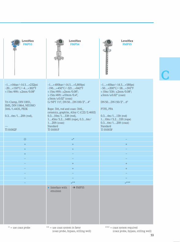
5353
C
Levelflex
FMP53
Levelflex
FMP54
Levelflex
FMP55
psi
°F
;
11851,
e)
–1…+16bar/–14.5…+232psi
–20…+150°C/–4…+302°F
< 15m/49ft: ±2mm/0.08"
Tri-Clamp, DIN 11851,
SMS, DIN 11864, NEUMO
316L/1.4435, PEEK
0.3…6m/1…20ft (rod),
—
TI 01002F
–1…+400bar/–14.5…+5,800psi
–196…+450°C/–321…+842°F
< 15m/49ft: ±2mm/0.08";
> 15m/49ft: ±10mm/0.4",
±5mm/±0.02" (coax)
G/NPT 1½", DN 50…DN 100/2"…4"
Rope: 316, rod and coax: 316L,
ceramics, graphite, Alloy C (C22/2.4602)
0.3…10m/1…33ft (rod),
1…45m/3.2…148ft (rope), 0.3…6m/
1…20ft (coax)
Standard
TI 01001F
–1…+40bar/–14.5…+580psi
–50…+200°C/–58…+392°F
< 10m/33ft: ±2mm/0.08";
±5mm/±0.02" (coax)
DN 50…DN 150/2"…6"
PTFE, PFA
0.3…4m/1…13ft (rod)
1…10m//3.2…33ft (rope)
0.3…6m/1…20ft (coax)
Standard
TI 01003F
O +* –
+ + +
+ + –
+ – –
– – –
– + +
– + +
– – –
– – –
– +** +***
MP54
MP55
• Interface with
emulsion
FMP55
* = use coax probe ** = use coax system in favor
(coax probe, bypass, stilling well)
*** = coax system required
(coax probe, bypass, stilling well)
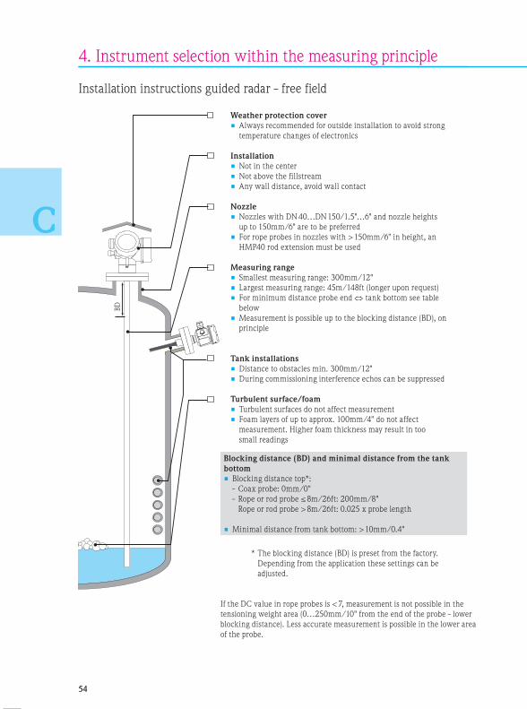
BD
5454
C
Installation instructions guided radar - free field
4. Instrument selection within the measuring principle
Weather protection cover
• Always recommended for outside installation to avoid strong
temperature changes of electronics
Installation
• Not in the center
• Not above the fillstream
• Any wall distance, avoid wall contact
Nozzle
• Nozzles with DN 40…DN 150/1.5"…6" and nozzle heights
up to 150mm/6" are to be preferred
• For rope probes in nozzles with > 150mm/6" in height, an
HMP40 rod extension must be used
Measuring range
• Smallest measuring range: 300mm/12"
• Largest measuring range: 45m/148ft (longer upon request)
• For minimum distance probe end tank bottom see table
below
• Measurement is possible up to the blocking distance (BD), on
principle
Tank installations
• Distance to obstacles min. 300mm/12"
• During commissioning interference echos can be suppressed
Turbulent surface/foam
• Turbulent surfaces do not affect measurement
• Foam layers of up to approx. 100mm/4" do not affect
measurement. Higher foam thickness may result in too
small readings
Blocking distance (BD) and minimal distance from the tank
bottom
• Blocking distance top*:
- Coax probe: 0mm/0"
- Rope or rod probe ≤ 8m/26ft: 200mm/8"
Rope or rod probe > 8m/26ft: 0.025 x probe length
• Minimal distance from tank bottom: > 10mm/0.4"
* The blocking distance (BD) is preset from the factory.
Depending from the application these settings can be
adjusted.
If the DC value in rope probes is < 7, measurement is not possible in the
tensioning weight area (0…250mm/10" from the end of the probe - lower
blocking distance). Less accurate measurement is possible in the lower area
of the probe.

5555
C
Installation instructions guided radar – stilling well/bypass
Weather protection cover
• Always recommended for outside installation to avoid strong
temperature changes of electronics
Measuring range
• Smallest measuring range: 300mm/12"
• Largest measuring range: 10m/33ft (longer upon request)
Pipe diameter
• Pipes of DN 40 … DN 150/1.5"…6" are to be preferred, these
diameters do not have any top blocking distance, measurement
is possible up to the bottom edge of the process connection
Bypass/measuring tube
• Metallic pipe
• No special requirements of bypass pipe or stilling well
• Welding seams protruding internally up to approx. 5mm/0.2" do
not impair measurement
• Wall contact by rod probes must be excluded. Use a centering disk
at the end of the probe, if required
Additional instructions for interface measurement
• Rod probes can be installed up to a diameter of 100mm/4".
For larger diameters, a coax probe is recommended
• The pipe must not have any gradation
• In case of interface layer measurement, the centering disk must be
of plastic material
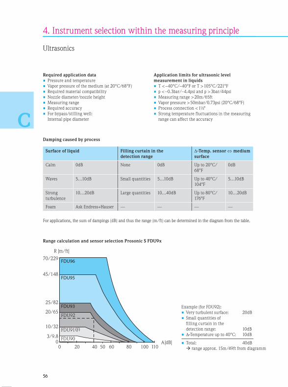
0 20 40 60 80 100 110
45/148
70/229
25/82
20/65
10/32
0
FDU95
FDU96
FDU93
FDU92
A[dB]
R [m/ft]
FDU903/9.8FDU91 F
50
( )
5656
C
4. Instrument selection within the measuring principle
Required application data
• Pressure and temperature
• Vapor pressure of the medium (at 20°C/68°F)
• Required material compatibility
• Nozzle diameter/nozzle height
• Measuring range
• Required accuracy
• For bypass/stilling well:
Internal pipe diameter
Application limits for ultrasonic level
measurement in liquids
• T < –40°C/–40°F or T > 105°C/221°F
• p < –0.3bar/–4.4psi and p > 3bar/44psi
• Measuring range > 20m/65ft
• Vapor pressure > 50mbar/0.73psi (20°C/68°F)
• Process connection < 1½"
• Strong temperature fluctuations in the measuring
range can affect the accuracy
Ultrasonics
Example (for FDU92):
• Very turbulent surface: 20dB
• Small quantities of
filling curtain in the
detection range: 10dB
• -Temperature up to 40°C: 10dB
• Total: 40dB
range approx. 15m/49ft from diagramm
Damping caused by process
Surface of liquid Filling curtain in the
detection range
-Temp. sensor medium
surface
Calm 0dB None 0dB Up to 20°C/
68°F
0dB
Waves 5…10dB Small quantities 5…10dB Up to 40°C/
104°F
5…10dB
Strong
turbulence
10…20dB Large quantities 10…40dB Up to 80°C/
176°F
10…20dB
Foam Ask Endress+Hauser — — — —
For applications, the sum of dampings (dB) and thus the range (m/ft) can be determined in the diagram from the table.
Range calculation and sensor selection Prosonic S FDU9x
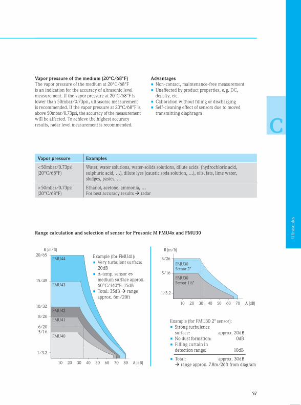
FMU40
FMU41
FMU43
FMU44
10 20 30 40 50 60 70 80
1/3.2
5/166/20
8/26
10/32
15/49
20/65
FMU42
R [m/ft]
A [dB]
5757
C
Vapor pressure Examples
< 50mbar/0.73psi
(20°C/68°F)
Water, water solutions, water-solids solutions, dilute acids (hydrochloric acid,
sulphuric acid, …), dilute lyes (caustic soda solution, …), oils, fats, lime water,
sludges, pastes, …
> 50mbar/0.73psi
(20°C/68°F)
Ethanol, acetone, ammonia, …
For best accuracy results radar
Range calculation and selection of sensor for Prosonic M FMU4x and FMU30
Vapor pressure of the medium (20°C/68°F)
The vapor pressure of the medium at 20°C/68°F
is an indication for the accuracy of ultrasonic level
measurement. If the vapor pressure at 20°C/68°F is
lower than 50mbar/0.73psi, ultrasonic measurement
is recommended. If the vapor pressure at 20°C/68°F is
above 50mbar/0.73psi, the accuracy of the measurement
will be affected. To achieve the highest accuracy
results, radar level measurement is recommended.
Advantages
• Non-contact, maintenance-free measurement
• Unaffected by product properties, e. g. DC,
density, etc.
• Calibration without filling or discharging
• Self-cleaning effect of sensors due to moved
transmitting diaphragm
Example (for FMU41):
• Very turbulent surface:
20dB
• -temp. sensor
medium surface approx.
60°C/140°F: 15dB
• Total: 35dB range
approx. 6m/20ft
Example (for FMU30 2" sensor):
• Strong turbulence
surface: approx. 20dB
• No dust formation: 0dB
• Filling curtain in
detection range: 10dB
• Total: approx. 30dB
range approx. 7.8m/26ft from diagram
Ult
raso
nic
s

5858
C
4. Instrument selection within the measuring principle
Ultrasonics – process industry
Prosonic T
FMU30
Prosonic M
FMU40/41
Prosonic M
FMU42/44
Technical data
• Process pressure
• Process temperature
• Accuracy
• Process connection
• Wetted parts
• Measuring ranges
• Point level detection
• Technical Information
–0.3…+2bar/–4.4…+29psi
–20…+60°C/–4…+140°F
±3mm/±0.12" or 0.2% of
distance
G/NPT 1½" or 2"
PP/EPDM
0.25…5m/0.8…16ft (1½")
0.35…8m/1.1…26ft (2")
—
TI 440F
–0.3…+2bar/–4.4…+29psi
–40…+80°C/–40…+176°F
±2mm/±0.08" or 0.2% of
distance
G/NPT/1½" or 2"
PVDF/EPDM
0.25…5m/0.8…16ft (FMU40)
0.35…8m/1.1…26ft (FMU41)
—
TI 365F
–0.3…+1.5bar/–4.4…+22psi
–40…+80°C/–40…+176°F
±4mm/±0.16" or 0.2% of
distance
DN 80/100/150/200,
ANSI 3"/4"/6"/8", JIS 10K/
80 (100)/100 (150/200)
PVDF/EPDM/Viton
0.4…10m/1.3…32ft (FMU42)
0.5…20m/1.6…65ft (FMU44)
—
TI 365F
–0.3…+
–40…+
±2mm/
distance
rear side
ceiling m
front sid
PVDF
0.07…3
1, 3 or 6
TI 396 /
Applications 1½" 2" FMU40 FMU41 FMU42 FMU44
Horizontal storage tank cyl. + O + O O –
Vertical storage tank + + + + + +
Buffer tank – – + O – –
Recipient tank – – – – – –
Process tank O O + + + +
Stilling well O O + + + +
Bypass – – – – – –
Pump shaft O O O O O O
Channel measurement O O O O O O
Application limits • For higher
resistance
• Foam/high
turbulence
possible
• Fast
filling and
discharging
rate
• Point level
detection
FMU42,
FDU9x
FMU30 (2")
FMU42,
FDU91
FMU90 +
FDU9x
FMU90 +
FDU9x
• For higher
resistance
• Foam/
high
turbulence
possible
• Fast
filling and
discharging
rate
• Point level
detection
FMU42,
FDU9x
FMU41,
FMU42/
FDU91
FMU90 +
FDU9x
FMU90 +
FDU9x
• Foam/
high
turbulence
possible
• Fast
filling and
discharging
rate
• Point level
detection
FMU44/
FDU92
FMU90 +
FDU9x
FMU90 +
FDU9x
• Foam
turbu
possib
• * For
farm
scann
FMU9
+ = recommended O = restricted (observe limits) – = not recommended

5959
C
Prosonic S
FDU90
Prosonic S
FMU90/95
FDU91
Prosonic S
FMU90/95
FDU91F
Prosonic S
FMU90/95
FDU92
+22psi
76°F
of
K/
)
MU42)
FMU44)
–0.3…+3bar/–4.4…+44psi
–40…+80°C/–40…+176°F
±2mm/±0.08" + 0.17% of
distance
rear side thread 1" G/NPT or
ceiling mounting option,
front side thread 1½" G/NPT
PVDF
0.07…3m/0.2…9.6ft
1, 3 or 6 relays
TI 396 / TI 397
–0.3…+3bar/–4.4…+44psi
–40…+80°C/–40…+176°F
±2mm/±0.08" + 0.17% of
distance
G/NPT 1"
(accessory flange FAX50)
PVDF
0.3…10m/1…32ft
1, 3 or 6 relays
TI 396 / TI 397
–0.3…+3bar/–4.4…+44psi
–40…+105°C/–40…+221°F
±2mm/±0.08" + 0.17% of
distance
G/NPT 1"
(accessory flange FAX50),
Tri-Clamp DN 80
316L
0.3…10m/1…32ft
1, 3 or 6 relays
TI 396 / TI 397
–0.3…+3bar/–4.4…+44psi
–40…+95°C/–40…+203°F
±4mm/±0.16" or 0.2% of
distance
G/NPT 1"
(accessory flange FAX50)
PVDF
0.4…20m/1.3…65ft
1, 3 or 6 relays
TI 396 / TI 397
MU44
– + + + O
+ +* +* +* +*
– + + + –
– – – – –
+ + + + +
+ + + + +
– – – – –
O + + O +
O + + O +
MU44/
U92
MU90 +
U9x
MU90 +
U9x
• Foam/high
turbulence
possible
• * For tank
farm
scanner
FMU95
FDU91 • Foam/high
turbulence
possible
• Flange-
flush
assembly
• * For tank
farm
scanner
FMU95
FDU92
FDU91F
• If foam/
high
turbulence
possible
• *For tank
farm
scanner
FMU95
FDU92 • *For tank farm
scanner FMU95
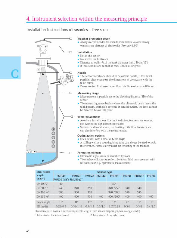
BD
6060
C
4. Instrument selection within the measuring principle
Installation instructions ultrasonics – free space
Weather protection cover
• Always recommended for outside installation to avoid strong
temperature changes of electronics (Prosonic M/S)
Installation
• Not in the center
• Not above the fillstream
• Distance to wall: ~1/6 of the tank diameter (min. 30cm/12")
• If these conditions cannot be met: Check stilling well
Nozzle
• The sensor membrane should be below the nozzle, if this is not
possible, please compare the dimensions of the nozzle with the
table below
• Please contact Endress+Hauser if nozzle dimensions are different
Measuring range
• Measurement is possible up to the blocking distance (BD) of the
sensor
• The measuring range begins where the ultrasonic beam meets the
tank bottom. With dish bottoms or conical outlets, the level cannot
be detected below this point
Tank installations
• Avoid any installations like limit switches, temperature sensors,
etc. within the signal beam (see table)
• Symmetrical installations, i. e. heating coils, flow breakers, etc.
can also interfere with the measurement
Optimization options
• Use a sensor with a smaller beam angle
• A stilling well or a sound guiding tube can always be used to avoid
interference. Please clarify build-up tendency of the medium
Formation of foam
• Ultrasonic signals may be absorbed by foam
• The surface of foam can reflect. Solution: Trial measurement with
ultrasonics or e. g. hydrostatic measurement
Max. nozzle
length
(mm/")
Sensor type
FMU40
FMU30 (1½")
FMU41
FMU30 (2")
FMU42 FMU44 FDU90 FDU91 FDU91F FDU92
DN 50 /2" 80 502
DN 80 /3" 240 240 250 3401/2502 340 340
DN 100 /4" 300 300 300 3901/3002 390 390
DN 150 /6" 400 400 400 400 4001/3002 400 400 400
Beam angle 11° 11° 11° 11° 12° 9° 12° 11°
BD (m/ft) 0.25/0.8 0.35/1.15 0.4/1.3 0.5/1.6 0.07/0.23 0.3/1 0.3/1 0.4/1.3
Recommended nozzle dimensions, nozzle length from sensor diaphragm, beam angle (3 dB)
1 Mounted at backside thread 2 Mounted at frontside thread
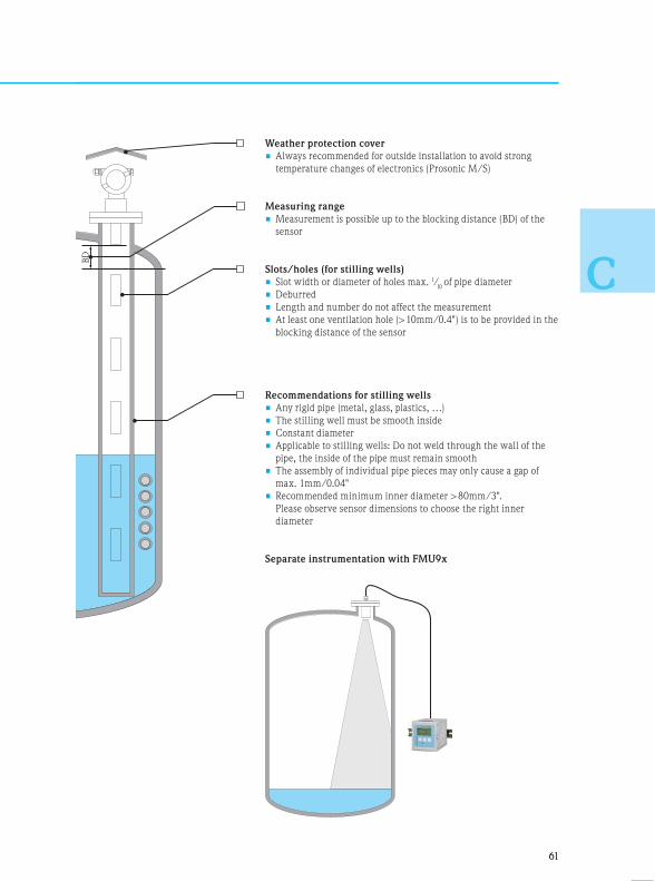
BD
6161
C
Weather protection cover
• Always recommended for outside installation to avoid strong
temperature changes of electronics (Prosonic M/S)
Measuring range
• Measurement is possible up to the blocking distance (BD) of the
sensor
Slots/holes (for stilling wells)
• Slot width or diameter of holes max. 1/10 of pipe diameter
• Deburred
• Length and number do not affect the measurement
• At least one ventilation hole (> 10mm/0.4") is to be provided in the
blocking distance of the sensor
Recommendations for stilling wells
• Any rigid pipe (metal, glass, plastics, …)
• The stilling well must be smooth inside
• Constant diameter
• Applicable to stilling wells: Do not weld through the wall of the
pipe, the inside of the pipe must remain smooth
• The assembly of individual pipe pieces may only cause a gap of
max. 1mm/0.04"
• Recommended minimum inner diameter > 80mm/3".
Please observe sensor dimensions to choose the right inner
diameter
Separate instrumentation with FMU9x

104
103
102
10
1
10–1
10–2
10–3
6262
C
Techn
• Pro
• Pro
• Acc
• Pro
• We
• Me
• Gas
• Tec
Appli
Horiz
Vertic
Buffer
Recipi
Proce
Stillin
Bypas
Pump
Chann
Interfa
Appli
+ = rec
4. Instrument selection within the measuring principle
Capacitance
Required application data
• Pressure and temperature
• Conductivity/dielectric
constant of the medium (DC)/
media group
• Required material compatibility
• Measuring range
• Required accuracy
• Mounting position
Starting from a conductivity of
100μS/cm the measured value
is not affected by the dielectric
constant and the conductivity of
the medium.
The following table describes
different media.
For reliable measurement:
Provide proper ground connection
between process connection and
tank. If required, establish ground
connection by potential com-
pensation line. In plastic tanks,
use probe with a ground tube or
double rod probe Liquicap T, if
possible.
Application limits for capacitance
level measurement
• T < –80°C/–112°F or
T > +200°C/+392°F
• p > 100bar/1,450psi
• Measuring range > 10m/3.2ft
Operating range of Liquicap M
The accuracy is unaffected by the conductivity and
the DC value (dielectric constant)
Factory calibration for 0% and 100%
The accuracy is dependent on the DC value and the
conductivity of the medium. Measurement not
recommended, select another measuring principle.
Factory calibration for 0%
The accuracy is dependent on the DC value.
e. g. water-based liquids,
aqueous solutions of salts,
acids, lyes, aqueous dispersions
and emulsions, waste water,
electrolytes, beverages
e. g. hydrocarbons with a
higher water content,
demineralized water
e. g. hydrocarbons with a
water content below 0.1%,
petrols, oils, solvents
Conductivity (μS/cm)

6363
C
Capacitance – process industry
Liquicap M
FMI51
Liquicap M
FMI52
Liquicap T
FMI21
Technical data
• Process pressure
• Process temperature
• Accuracy
• Process connection
• Wetted parts
• Measuring ranges
• Gastight feedthrough
• Technical Information
–1…+100bar/-14.5…+1,450psi
–80…+200°C/–112…+392°F
±1%
Thread ½"…1½", Flanges EN,
ANSI, JIS, hygienic
316L, PFA, PTFE
Rod probe up to 4m/13ft
Optional
TI 00401F
–1…+100bar/-14.5…+1,450psi
–80…+200°C/–112…+392°F
±1%
Thread ½"…1½", Flanges EN,
ANSI, JIS, hygienic
316L, PFA, FEP
Rope probe up to 10m/32ft
Optional
TI 00401F
–1…+10bar/-14.5…+145psi
–40…+100°C/–40…+212°F
±1%
Thread 1½"
316L, PP, carbon fiber
to 2.5m/8.2ft
—
TI 393F
Applications
Horizontal storage tank cyl. + O +
Vertical storage tank + + +
Buffer tank + – –
Recipient tank + – –
Process tank + – –
Stilling well + O –
Bypass + O –
Pump shaft O O O
Channel measurement – – –
Interface measurement + + –
Application limits • Insufficient clearance
towards ceiling
• Changing, non-conductive
media or conductivity
between 1…100μs/cm
• Changing, non-conductive
media or conductivity
between 1…100μs/cm
• Changing, non-conductive
media or conductivity
between 1…100μs/cm
• Highly viscous liquids
> 2000cst
+ = recommended O = restricted (observe limits) – = not recommended
Cap
acit
an
ce

L1
6464
C
4. Instrument selection within the measuring principle
Installation instructions capacitance
Weather protection cover
• Always recommended for outside installation to avoid strong
temperature changes of electronics
Installation
• Not above the fillstream
• Establish proper ground connection between sensor and tank wall
• Use ground tube in non-conductive tanks (e. g. of plastic material)
Nozzle
• Use inactive length for installation in a nozzle
Measuring range
• Measuring range L1 possible from the tip of the probe to the
process connection
• Particularly suited to small tanks in fast filling and discharging
operations
Tank installations
• Obstacles do not affect the measurement
Foam of formation
• In slight foam formation, the „Build-up compensation“ mode may
be selected

6565
C
Notes

6666
C
Hydrostatics (pressure / differential pressure)
Required application data
• Pressure and temperature
• Medium density
• Required material compatibility
• Process connection
• Measuring range
• Required accuracy
• Ambient conditions (temperature change,
moisture, …)
Application limits for hydrostatic level
measurement
• T < –70°C/–94°F or
T > +400°C/+752°F
• p > 420bar/6,090psi
Advantages
• Unaffected by surface foam
• Unaffected by tank obstacles/tank geometries
• Simple engineering
• Established technology
4. Instrument selection within the measuring principle
6767
C
Notes
Hyd
rost
atic
s

6868
C
4. Instrument selection within the measuring principle
Cerabar M
PMC51
Cerabar M
PMP55
Deltapilot M
FMB50
Technical data
• Process pressure
• Process temperature
• Accuracy
• Process connection
• Wetted parts
• Gastight feedthrough
• Measuring cell
• Technical Information
10mbar…40bar/
0.15…580psi
–40…+125°C/
–40…+257°F
±0.2% (0.1% option)
Thread, flange, hygienic
connections
316L, Al2O
3, sealings , PVDF
—
Ceramics
TI 00436P
100mbar…40bar/
1.5…580psi
–70…+400°C/
–94…+752°F
±0.2%
Thread, flange, hygienic
connections
316L, Alloy, Tantal, PTFE
—
Metal welded
TI 00436P
100mbar…10bar/
1.5…145psi
–10…+100°C/
+14…+212°F
±0.2% (0.1% option)
Thread, flange, hygienic
connections
316L, Alloy
—
Contite, condensate-proof,
water-tight, metal welded
TI 00437P
5mbar…
0.07…5
–40…+
–40…+
±0.075
Thread
connec
316L, A
Standa
Ceram
TI 383P
Applications
Horizontal storage tank cyl. O O O
Vertical storage tank + + +
Buffer tank O O O
Recipient tank O – O
Process tank O O +
Stilling well – – –
Bypass – – –
Pump shaft – – –
Channel measurement – – –
Application limits • If pressurized, possibly use
differential pressure
measurement with two
pressure transmitters
(electronic dp). Observe
ratio head pressure to
hydrostatic pressure
• If pressurized, possibly use
differential pressure
measurement with two
pressure transmitters
(electronic dp). Observe
ratio head pressure to
hydrostatic pressure
• If pressurized, possibly use
differential pressure
measurement with two
pressure transmitters.
Observe ratio head pressure
to hydrostatic pressure
• If pre
diffe
mea
press
(elec
ratio
hydr
+ = recommended O = restricted (observe limits) – = not recommended
Hydrostatics – process industry

6969
C
Cerabar S
PMC71
Cerabar S
PMP75
Deltapilot S
FMB70
of,
ed
5mbar…40bar/
0.07…580psi
–40…+150°C/
–40…+302°F
±0.075% (0.05% option)
Thread, flange, hygienic
connections
316L, Al2O
3, sealings, PVDF
Standard
Ceramics
TI 383P
40mbar…400bar/
0.58…5800psi
–40…+400°C/
–40…+752°F
±0.075%
Thread, flange, hygienic
connections
316L, Alloy, Tantal, PTFE
Standard
Metal welded
TI 383P
5mbar…10bar/
0.07…145psi
–10…+100°C/
+14…+212°F
±0.1%
Thread, flange, hygienic
connections
316L, Alloy
Standard
Contite, condensate-proof,
water-tight, metal welded
TI 416P
O O O
+ + +
O O O
O – O
O O +
– – –
– – –
– – –
– – –
y use
wo
essure
e
• If pressurized, possibly use
differential pressure
measurement with two
pressure transmitters
(electronic dp). Observe
ratio head pressure to
hydrostatic pressure
• If pressurized, possibly
use differential pressure
measurement with two
pressure transmitters
(electronic dp). Observe
ratio head pressure to
hydrostatic pressure
• If pressurized, possibly use
differential pressure
meas-urement with two
pressure transmitters.
Observe ratio head
pressure to hydrostatic
pressure

7070
C
4. Instrument selection within the measuring principle
+ =
Waterpilot
FMX167/FMX21
Deltapilot M
FMB51/52/53
Deltabar M
PMD55
Technical data
• Process pressure
• Process temperature
• Accuracy
• Process connection
• Wetted parts
• Gastight feedthrough
• Measuring cell
• Technical Information
100mbar…20bar
0.15…290psi
–10…+70°C/
+14…+158°F
±0.2%
Mounting clamp, cable
mounting screw
316L, Al2O
3, FKM, EPDM, PE,
FEP, PUR
—
Ceramics
TI 00351P/TI 413P
5mbar…10bar/
0.07…145psi
–10…+80°C/
+14…+176°F
±0.2% (0.1% option)
Thread, flange
316L, Alloy, PE, FEP
—
Contite, condensate-proof,
water-tight, metal welded
TI 00437P
1mbar…40bar/
0.1…580psi
–40…+85°C/
–40…+185°F
±0.1% (0.075% option)
Oval flange (¼…18 NPT),
IEC 61518
316L, Alloy
—
Metal welded
TI 00434P
400m
0.15…
–40…
–40…
Single
System
Threa
hygie
316L,
Stand
Metal
TI 103
Applications
Horizontal storage tank cyl. – + O
Vertical storage tank – + O
Buffer tank – O +
Recipient tank – O –
Process tank – – +
Stilling well – – –
Bypass – – O
Pump shaft + +* –
Channel measurement O O –
Application limits • If pressurized, possibly
use Deltabar FMD72
electronic dp. Observe
ratio head pressure to
hydrostatic pressure
• FMB51: Rope variant
FMB52: Rod variant
*In case of an open tank or shaft use DB53 with mounting clamp.

7171
C
+ = recommended O = restricted (observe limits) – = not recommended
Deltabar
FMD72
Deltabar S
PMD75
Deltabar S
FMD77
Deltabar S
FMD78
),
400mbar…10bar/
0.15…145psi
–40…+125°C/
–40…+257°F
Single sensor ±0.05%
System ±0.07%
Thread, flange, flush-mounted
hygienic connections
316L, Alloy C276
Standard
Metal welded
TI 1033P
1mbar…40bar/
0.1…580psi
–40…+125°C/
–40…+257°F
±0.075% (0.05% option)
Oval flange (¼…18 NPT),
IEC 61518
316L, Alloy, Monel, Tantal
Standard
Metal welded
TI 382P
10mbar…16bar/
0.15…232psi
–40…+400°C/
–40…+752°F
±0.075%
Flanges
316L, Alloy, Monel, Tantal,
PTFE
Standard
Metal welded
TI 382P
10mbar…16bar/
0.15…232psi
–70…+400°C/
–94…+752°F
±0.075%
Thread, flange, hygienic
connections
316L, Alloy, Monel, Tantal,
PTFE
Standard
Metal welded
TI 382P
O O O O
+ O O O
O + + O
O – – –
+ + + +
– – – –
– O – O
– – – –
– – – –

7272
C
4. Instrument selection within the measuring principle
Installation instructions hydrostatics (pressure)open tanks
Weather protection cover
• Recommended for outside installation to avoid
strong temperature changes of electronics
Installation from the top (FMB51/52)
• When installing rod and cable versions, please
ensure that the head of the probe is at a location
which is as free of flow as possible
• In order to protect the probe against contact by
lateral movements, install probe in a guide tube
(preferably of plastics) or use an anchoring device
• The length of the carrier cable or the probe rod
depends on the envisaged level zero point. The tip
of the probe should be at least 5cm/2" below that
Installation from below (PMC51, PMP55, FMB50,
PMC71, PMP75, FMB70)
• Always install the instrument below the lowest
measuring point
• It is recommended to install the pressure transmitter
behind a stop valve to facilitate easy cleaning and
functioning checks
• Do not install the instrument in the following
positions:
– in the flow of product as it is filled
– in the tank outlet
– at a location in the tank which might be affected
by the pressure impulses of the agitator
• In case of media which might cure as they cool
down, the instrument must be included in the
insulation
Foam of formation
• Foam of formation does not have any noticeable
influence on hydrostatic level measurement
Tank installations
• Obstacles do not affect hydrostatic level
measurement

7373
CField housing/terminal box
• The sensor is connected to a field housing or
terminal box via a carrier cable. Both offer optimum
moisture and condensate protection and are suited
to outdoor installation
• If a terminal box is not used in FMX167/FMX21,
the cable must end in a dry room
Mounting clamp/cable mounting screw
• The carrier cable is fastened by an mounting
clamp/cable mounting screw above the well or
basin
Guide tube
• Lateral movement of the level probe might cause
measuring errors. Therefore, install the probe in a
location which is free of flow and turbulences or
use a guide tube
• The internal diameter of the guide tube should be at
least 1mm/0.04" larger than the external diameter
of the selected sensor
• An additional weight may be ordered as an accessory
open wells or basins (FMB53/FMX167/FMX21)
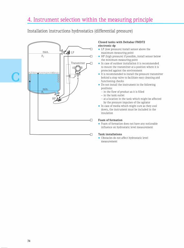
7474
C
4. Instrument selection within the measuring principle
Installation instructions hydrostatics (differential pressure)
Closed tanks with Deltabar FMD72
electronic dp
• LP (low pressure) install sensor above the
maximum measuring point
• HP (high pressure) if possible, install sensor below
the minimum measuring point
• In case of outdoor installation it is recommended
to mount the transmitter at a position where it is
protected against the environment
• It is recommended to install the pressure transmitter
behind a stop valve to facilitate easy cleaning and
functioning checks
• Do not install the instrument in the following
positions:
– in the flow of product as it is filled
– in the tank outlet
– at a location in the tank which might be affected
by the pressure impulses of the agitator
• In case of media which might cure as they cool
down, the instrument must be included in the
insulation
Foam of formation
• Foam of formation does not have any noticeable
influence on hydrostatic level measurement
Tank installations
• Obstacles do not affect hydrostatic level
measurement
min.
max. LP
Transmitter
HP
p1
p2

+
–
7575
C
Closed tanks with FMD77
(diaphragm seal plus side)
• Always connect the minus side above the
maximum level
• Install Deltabar S FMD77 directly at the tank below
the lower measuring connection
• Generally speaking, the installation of separators
and discharge valves makes sense to collect
deposits, pollution or liquids in the upper pressure
piping and to remove them
• Calibrate at operating temperaturemin.
max.
p1
p2
min.
max.
p1
p2
min.
max.
p1
p2
Closed tanks with PMD75/PMD55
(pressure piping)
• Always connect the minus side above the
maximum level
• Always install Deltabar S PMD75 / Deltabar M
PMD55 below the lower measuring connection so
that the lower pressure piping is always filled with
liquid
• Generally speaking, the installation of separators
and discharge valves makes sense to collect
deposits, pollution or liquids in pressure piping
and to remove them
• Calibrate at operating temperature
Closed vapor-pressurized tanks with PMD75/
PMD55 (pressure piping)
• Always connect the minus side above the
maximum level
• The filled condensate vessel safeguards constant
pressure on the minus side
• Always install Deltabar S PMD75 / Deltabar M
PMD55 below the lower measuring connection so
that the lower pressure piping is always filled with
liquid
• In case of measurements in media with a solids
content, e. g. polluted liquids, the installation of
separators and discharge valves makes sense to
collect deposits and remove them
• Calibrate at operating temperature

76
Closed tanks with FMD78
(capillary diaphragm seal)
• Level measurement is only safeguarded between
the upper edge of the lower and the lower edge of
the upper diaphragm seal
• In vacuum applications, it is recommended to
install the pressure transmitter below the lower
diaphragm seal. This will avoid a vacuum load of
the diaphragm seal caused by the presence of filling
oil in the capillaries
Optimizing measures
• In order to avoid additional pressure fluctuations
and a defective instrument, the capillaries should
be installed free of vibrations
• The capillaries may not be installed in the vicinity
of heating or cooling pipes which would impair
exact measuring results
• It is recommended to insulate the capillaries in a
colder or warmer environment, if appropriate apply
Deltabar electronic dp
• In case of two-sided diaphragm seal systems, the
ambient temperature and the length of both
capillaries should be identical
• Two identical diaphragm seals (e. g. diameter,
material, etc.) should always be used for the minus
and plus side
Installation of the pressure transmitter above
the lower diaphragm seal
• If the pressure transmitter is installed above the
lower diaphragm seal, the maximum height (see
Technical Information) may not be exceeded
• The maximum difference in height depends on the
density of the filling oil and the lowest pressure
which may occur in the diaphragm seal of the plus
side (empty tank) at any time
min.
max.
p1
p2
min.
max.
p1
p2
4. Instrument selection within the measuring principle

Products Solutions Services
Continuous level measurement in bulk solidsSelection and engineering guide for the process industry

78
Step by step
This selection and engineering guide provides information on different
measuring principles for continuous level measurement in Bulk solids as
well as their application and installation.
The pamphlet contains two separate chapters: Level measurement in
liquids and Level measurement in solids.
The second chapter specifically covers continuous measurement in liquids.
A separate selection guide is available for point level detection (see the
supplementary documentation CP00007F).
Selection of the measuring
principle
The appropriate measur-
ing principle is first selected
according to the application
and its criteria (Silo/bunker,
slim/narrow silos, mechanical
conveyor systems, crusher and
stockpiles).
Select the principle which
meets, if possible, all of the
criteria required by you or your
plant. The measuring principles
are classified according to „non-
contact“ and „contact“ criteria.
The ideal measuring principle/
instrument is stated first and in
a blue frame.
Max. technical data is always
used.
Instrument selection
Now change to the area of the
selected measuring principle
where you can chose the
appropriate instrument from a
product family.
Compare your application and
process data with the instru-
ment data.
Engineering
After the selection of the
optimum instrument check the
installation instructions at the
end of the respective measuring
principle. They contain basic
directions for the safe installa-
tion and use of the instrument.
You will find more extensive
engineering instructions in the
respective Technical Informa-
tion of the instrument.
B C
Overview of measuring
principles
First of all, we show you an
overview of the Endress+Hauser
measuring principles for
continuous level measurement
in solids in diagrams on the first
pages. Subsequently, you are
introduced to the mode of
functioning of the measuring
principle and the respective
product family.
Checklist
You should be aware of the
application requirements for the
correct selection of a suitable
instrument. The checklist pro-
vides an overview and is sup-
posed to help you to consider or
record this data as completely
as possible.
A

79
Contents
1. Overview of measuring principles . . . . . . . . . . . . . . . . . . . . . . . . . . . 80
2. Checklist . . . . . . . . . . . . . . . . . . . . . . . . . . . . . . . . . . . . . . . . . . . . . 86
3. Selection of the measuring principle according to the application . . . . 88• Silo/bunker . . . . . . . . . . . . . . . . . . . . . . . . . . . . . . . . . . . . . . . . . . . . .88
• Slim, narrow silos (ratio H/D ≥ 8) . . . . . . . . . . . . . . . . . . . . . . . . . . . .90
• Stockpiles . . . . . . . . . . . . . . . . . . . . . . . . . . . . . . . . . . . . . . . . . . . . . .92
• Mechanical conveyor systems (e. g. conveyor belt) . . . . . . . . . . . . . . . . 93
• Crusher . . . . . . . . . . . . . . . . . . . . . . . . . . . . . . . . . . . . . . . . . . . . . . . . 94
4. Instrument selection within the measuring principle . . . . . . . . . . . . . 96• Radar . . . . . . . . . . . . . . . . . . . . . . . . . . . . . . . . . . . . . . . . . . . . . . . . . .96
• Guided radar . . . . . . . . . . . . . . . . . . . . . . . . . . . . . . . . . . . . . . . . . . . 100
• Ultrasonics . . . . . . . . . . . . . . . . . . . . . . . . . . . . . . . . . . . . . . . . . . . . 104
• Electromechanical level system . . . . . . . . . . . . . . . . . . . . . . . . . . . . . 110
• Radiometrics: The radiometric measuring principle is not considered in
this section. Please contact our application consultants in your country
for detailed information.
A
B
C

8080
A
Point level Continuous
Liquids VibronicsConductiveCapacitanceFloat switchRadiometrics
RadarGuided radarUltrasonics
HydrostaticsCapacitanceRadiometrics
Bulk solids VibronicsCapacitance
PaddleMicrowave barrier
Radiometrics
Guided radarRadar
UltrasonicsElectromechanical level
systemRadiometrics
1. Overview of the measuring principles
Segmentation
Process conditions*
Grain size (mm/")
Radar
Electromechanical level measurement
Guided radar
Ultrasonics
Silo height (m/ft)
* Radiometry not depicted:
Non-contact measurement from outside and, therefore, no application limits.
> 50/1.9720/0.79
35/115
40/131
45/148
50/164
70/230
8181
A
„You only pay what you really need“.
Endress+Hauser takes this statement seriously and offers a large number of different
measuring principles which vary in price and functionality.
Endress+Hauser offers you a solution adapted to your application and tailored to your
process requirements.
You can select the best technology for your application from the wide product range of
Endress+Hauser.

8282
A 1. Overview of the measuring principles
Radar
Micropilot works with radar pulses
which are reflected by the medium
surface due to a change of the DC
value (relative dielectric constant)
between the air and the medium. The
time between pulse launching and
receiving is measured and analyzed by
the instrument and constitutes a direct
measure for the distance between the
antenna and the surface of the bulk
solids.
Micropilot
Non-contact, maintenance-free
measurement also under extreme
conditions. Unaffected by the density
of bulk solids, temperature, dust
formation and humidity.
Guided radar
Levelflex works with radar pulses
guided along a probe. As the pulses
meet the medium surface, part of the
emitted pulse is reflected due to a
change of the DC value between the
air and the medium. The time between
pulse launching and receiving is
measured and analyzed by the
instrument and constitutes a direct
measure for the distance between the
process connection and the product
surface.
Levelflex
Robust, non-maintenance measurement
in solids. Unaffected by the density
of bulk solids, temperature, dust
formation and humidity and almost
unaffected by baffles.
Ultrasonics
Prosonic works with ultrasonic pulses
which are emitted by a sensor, reflected
by the surface of the medium due to a
change of the density between the air
and the medium and again acquired by
the sensor. The required time of flight
is a measure for the distance travelled
in the empty part of the silo. This value
is deducted from the overall height of
the silo to yield the level.
Prosonic S/M/T
Non-contact measurement free of
maintenance without impairment
by product properties, e. g. dielectric
constant or humidity. Unaffected by
build-up due to the self-cleaning effect
of sensors using diaphragm vibration.
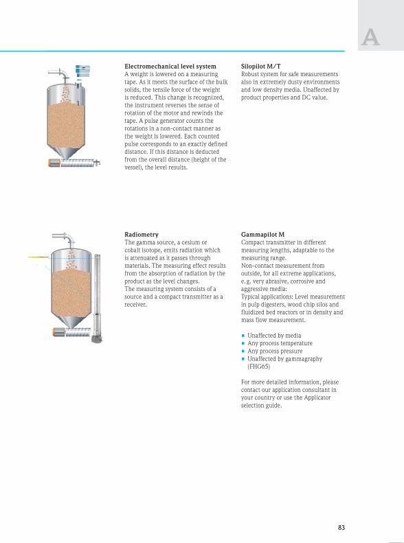
8383
AElectromechanical level system
A weight is lowered on a measuring
tape. As it meets the surface of the bulk
solids, the tensile force of the weight
is reduced. This change is recognized,
the instrument reverses the sense of
rotation of the motor and rewinds the
tape. A pulse generator counts the
rotations in a non-contact manner as
the weight is lowered. Each counted
pulse corresponds to an exactly defined
distance. If this distance is deducted
from the overall distance (height of the
vessel), the level results.
Silopilot M/T
Robust system for safe measurements
also in extremely dusty environments
and low density media. Unaffected by
product properties and DC value.
Radiometry
The gamma source, a cesium or
cobalt isotope, emits radiation which
is attenuated as it passes through
materials. The measuring effect results
from the absorption of radiation by the
product as the level changes.
The measuring system consists of a
source and a compact transmitter as a
receiver.
Gammapilot M
Compact transmitter in different
measuring lengths, adaptable to the
measuring range.
Non-contact measurement from
outside, for all extreme applications,
e. g. very abrasive, corrosive and
aggressive media:
Typical applications: Level measurement
in pulp digesters, wood chip silos and
fluidized bed reactors or in density and
mass flow measurement.
• Unaffected by media
• Any process temperature
• Any process pressure
• Unaffected by gammagraphy
(FHG65)
For more detailed information, please
contact our application consultant in
your country or use the Applicator
selection guide.

8484
A 1. Overview of the measuring principles
Radar Guided radar Ultrasonics Elec
Process temperature*
Process pressure
–40…+400°C/–40…+752°F
–1…+16bar/–14.5…+232psi
–40…+150°C/–40…+302°F
–1…+16bar/–14.5…+232psi
–40…+150°C/–40…+302°F
–0.3…+3bar/–4.4…+44psi
–20…
–0.2…
Measuring range 0.3…70m/1…230ft 0.2…45m/0.7…148ft 0.07…70m/0.2…230ft 0.92…
design
Instrument accuracySurfaces of bulk solids affect
accuracy
• Up to 2m/78": ±20mm/0.8"
• From 2m/78": ±3mm/0.12"
< 15m/49ft: ±2mm/0.08";
> 15m/49ft: ±10mm/0.4"
• ±2mm/0.08" + 0.17% of
measured distance
• ±1%
• ±5c
• ±2
Function may be
affected by
• Strong build-up formation
• Surface of bulk solids
(grain size/angled surface)
• Conductive build-up on
the antenna
• Strong fluidization
• Baffles causing interfering
reflections
• Build-up formation
• Baffles in the immediate
vicinity of the probe
• Strong fluidization
• Extreme dust formation
• Extreme filling noise
• Strong build-up formation
• Surface of bulk solids (grain
size/angled surface)
• Fluidization
• Baffles causing interfering
reflections
• Str
• We
me
• Bur
pro
Application limits • DC < 1.6
• Baffles in the beam cone
• Filling curtain in the beam
cone
• Angled surface/funnel
with a reflecting, smooth
surface
• DC < 1.4
• Coarse-grained
(> 20mm/0.8") and
abrasive media
• Extreme tensile forces
• Measurement in the
filling curtain
• Blocking distance
• Baffles in the sonic cone
• Filling curtain in the sonic
cone
• Angled surface/funnel with a
reflecting, smooth surface
• Ext
if th
pro
wa
• Me
filli
FMP57FM
FMU4x
FMU90/95
FDU9x
*At the process connection
FMP56
Ra
FMR57
FMR56

8585
A
Electromechanical level
system
Radiometrics
F –20…+230°C/–4…+446°F
–0.2…+2bar/–3…+29psi
Unaffected by process
temperature and pressure
0.92…70m/3…230ft (special
design up to 90m/295ft)
0.05...2m/0.16…6.5ft,
cascadable as required
• ±1% of the measuring range
• ±5cm/2" – FMM50
• ±2.5cm/1" – FMM20
• ±1% of the measuring
range
n
in
g
• Strong build-up formation
• Wear due to abrasion of
mech. components
• Burying due to collapsing
product accumulation
• Extreme build-up
formation
• Pressure fluctuation
• External radiation
(gammagraphy), solution
with Gamma Modulator
c
ith a
e
• Extreme tensile forces
if the risk of collapsing
product accumulation on
walls prevails
• Measurement during
filling
• Non-contact measurement
from outside and, there-
fore, no application limits
• Observe radiation
protection laws
• Further information from
our sales team
FMM50FMM20 FMG60
• Overview of application areas
• Limits of operating conditions

Notes
8686
A 2. Checklist
You need to know your specific application require-
ments for a correct selection. The checklist opposite
provides an overview of relevant process data and is
supposed to help you to take these into consideration.
If we have not included all of the data, please supple-
ment this list with your criteria.
The checklist is used both for the selection of the
measuring principle and the selection of the
instrument.
Tip
Copy this checklist and complete it to have all relevant
data readily available for the selection.

8787
AName of medium Please complete Notes
Medium Density g/l (kg/m³)
Grain size (min/max) mm/inch
Rel. dielectric constant (DC)
Tacky/build-up forming yes no
Extreme dust formation yes no
Abrasive yes no
Condensate formation yes no
Corrosive yes no
Non-contact
measurement
yes no
ApplicationsDrawing
available
Silos/bunkers yes no
Slim, narrow silos (H/D ≥ 8) yes no
Stockpiles yes no
Mechanical conveyor systems
(e. g. conveyor belt)
yes no
Crusher yes no
Process
conditions
Fluidization yes no
Pneumatic filling yes no
Product accumulation on walls yes no
Formation of angled surfaces,
outflow funnels
yes no
Max. measuring distance m/feet
Process data Process pressure min. max.
Temperature at the housing min. max.
Temperature at the process connection min. max.
Process temperature min. max.
Process
connection
Threaded connection yes no
Flange yes no
Size Ø
Pressure requirements min. max.
Hygiene requirements yes no
InstallationObserve max. ceiling
load in contacting
measuring methods
Concrete ceiling yes no
Thickness of concrete ceiling mm/inch
Electric
connection
2-wire 4...20mA yes no
4-wire DC, AC yes no
Surface
requirements
FDA-listed materials yes no
Approvals Ex (dust/gas) yes no
Special
requirements
Extreme external vibration yes no
Digital
communication
PROFIBUS® PA, PROFIBUS® DP,
HART®, FOUNDATION™ fieldbus
Other items

8888
B
3. Selection of measuring principle according to application
Our proposal
Radar
Micropilot
Ultrasonics
Prosonic S/M
Advantages • Unaffected by the density of bulk solids,
temperature, humidity and filling noise
• For corrosive and abrasive media
• Easy installation for large measuring
ranges
• Separate instrumentation
• Connection of up to 10 sensors
• Attractive price, e. g. silo farms
• Self-cleaning effect of sensors
• Corrosive and abrasive media
• Relay output for point levels
• Unaffected by the density of bulk solids,
humidity and dielectric constant
• Una
ang
• Una
tem
• Una
Technical data
• Connection
• Accuracy
• Process temperature*
• Process pressure
• Min. DC value
• Process connection
• Maximum measuring
range
2-wire (HART®, PA, FF), 4-wire HART®
±3mm/±0.12"
–40…+400°C/–40…+752°F
–1…+16bar/–14.5…+232psi
1.6
DN80, DN100, DN150, DN200, DN250,
Assembly bracket
70m/230ft
2-/4-wire (4-20mA HART®, DP, PA, FF)
±2mm/±0.08" +0.17% of measured distance
–40…+150°C/–40…+302°F
–0.3…+3bar/–4.4…+44psi
—
Threads, flanges (DIN, ANSI, JIS), wall and
assembly arm, assembly bracket
70m/230ft
2-wire
< 15m
–40…
–1…+
1.4
¾", 1½
45m/
Application limits • DC value < 1.6
• Low density
(< 10 g/l)
• Risk of strong
build-up
formation
• Angled surface/
funnel with
a reflecting,
smooth surface
ultrasonics,
electrom. level
system
electrom. level
system
use of purge air
ultrasonics
guided radar,
electrom. level
system
• Temperatures
> 150°C/302°F
• Media with strong
dust formation during
filling
• Extreme filling noise
• Angled surface/funnel
with a reflecting,
smooth surface
• Measuring range
> 35m/110ft in
powdery products
radar, electrom.
level system
radar,
guided radar
radar, guided radar
guided radar,
electrom. level
system
radar, guided radar,
electrom. level
system
• Abr
prod
prob
• Max
the
(obs
• Ext
form
• Hig
> 15
• DC
• Mea
148
• Low
FMU90/95
FMU4xFDU93
(separated) (compact)
FM
FDU95
Please note:
Radar continued on Page 96
Please note:
Ultrasonics continued on Page 104
Ple
Guided
*At the process
connection
FMR57
FMR56

8989
B
Silos/bunkers
• Filling via mechanical or pneumatic conveyance
• Measurement freely into the silo
• Fluidization possible
Our proposal
Guided radar
Levelflex
Electromechanical level system
Silopilot
• Unaffected by silo geometries and the shape of the
angled surfaces
• Unaffected by the density of bulk solids,
temperature, humidity and filling noise
• Unaffected by dust, e. g. in pneumatic filling
• Unaffected by low density of bulk solids
and DC value
• Easy installation
2-wire (HART®, PA, FF), 4-wire HART®
< 15m/49ft: ±2mm/0.08"; > 15m/49ft: ±10mm/0.4"
–40…+150°C/–40…+302°F
–1…+16bar/–14.5…+232psi
1.4
¾", 1½", DN40...DN150
45m/148ft
4-wire, 4-20mA, relay
±2.5cm/±1" (FMM20), ±5cm/±2" (FMM50)
–20…+230°C/–4…+446°F
–0.2...+2bar/–3…+29psi
—
DN100 PN16 (hole size)
70m/230ft (special design up to 90m/295ft)
m.
radar
el
radar,
el
• Abrasive, grained, lumpy
products (> 20 mm/0.8"),
probe damage
• Max. tensile forces on
the rope = 35kN
(observe ceiling load)
• Extreme build-up
formation on the probe
• High temperatures
> 150°C/302°F
• DC < 1.4
• Measuring range > 45m/
148ft powdery products
• Low density (< 10g/l)
radar,
ultrasonics
radar, ultrasonics,
electrom. level
system
radar with purge air,
ultrasonics
radar, electrom. level
system
ultrasonics, electrom.
level system
radar, electrom. level
system
electrom. level
system
• Risk of weight
being buried
• Strong
mechanical
wear to be
expected
• Measurement
during filling
radar, ultrasonics
radar,
ultrasonics
guided radar, radar,
ultrasonics
x
ct)
FMP57
FMM50 FMM20
Please note:
Guided radar continued on Page 100
Please note:
Electrom. level system continued on Page 110
FMFMP56
Sil
os
/ b
un
kers

9090
B
3. Selection of measuring principle according to application
Radar
Micropilot
Ultrasonics
Prosonic S/M
Advantages • Unaffected by the density of bulk solids,
temperature, humidity and filling noise
• For corrosive and abrasive media
• Easy installation for large measuring
ranges
• Separate instrumentation
• Connection of up to 10 sensors
• Attractive price, e. g. silo farms
• Self-cleaning effect of sensors
• Corrosive and abrasive media
• Relay output for point levels
• Unaffected by the density of bulk solids,
humidity and dielectric constant
• Una
ang
• Una
hum
• Una
Technical data
• Connection
• Accuracy
• Process temperature*
• Process pressure
• Min. DC value
• Process connection
• Maximum measuring
range
2-wire (HART®, PA, FF), 4-wire HART®
±3mm/±0.12”
–40…+400°C/–40…+752°F
–1…+16bar/–14.5…+232psi
1.6
DN80, DN100, DN150, DN200, DN250,
assembly bracket
70m/230ft
2-/4-wire (4-20mA HART®, DP, PA, FF)
±2mm/±0.08" +0.17% of measured distance
–40…+150°C/–40…+302°F
–0.3…+3bar/–4.4…+44psi
—
Threads, flanges (DIN, ANSI, JIS), wall and
assembly arm, assembly bracket
70m/230ft
2-wire
< 15m
–40…
–1…+
1.4
¾", 1½
45m/
Application limits • DC value < 1.6
• Low density
(< 10g/l)
• Risk of strong
build-up
formation
• Angled surface/
funnel with a
reflecting, smooth
surface
ultrasonics,
electrom. level
system
electrom. level
system
use of purge air
ultrasonics
guided radar,
electrom. level
system
• Temperatures
> 150°C/302°F
• Media with strong
dust formation during
filling
• Extreme filling noise
• Angled surface/funnel
with a reflecting,
smooth surface
• Measuring range
> 35m/110ft in
powdery products
radar, electrom.
level system
radar,
guided radar
radar, guided radar
guided radar,
electrom. level
system
radar, guided
radar, electrom.
level system
• Abr
pro
prob
• Ma
the
(obs
• Ext
on t
• Hig
> 15
• DC
• Me
148
• Low
FMU90/95
FMU4x
FDU93
(compact)
FM
FDU95
*At the process
connection
Please note:
Radar continued on Page 96
Please note:
Ultrasonics continued on Page 104
Ple
Guided
(separated)
FMR57
FMR56

9191
B
Slim, narrow silos, vessels
• Filling via mechanical or pneumatic conveyance
• Measurement freely into the silo
• Fluidization possible
• Ratio H/D ≥ 8
Our proposal
Guided radar
Levelflex
Electromechanical level system
Silopilot
• Unaffected by silo geometries and the shape of the
angled surfaces
• Unaffected by the density of bulk solids, temperature,
humidity and filling noise
• Unaffected by dust, e. g. in pneumatic filling
• Unaffected by low density of bulk solids
and DC value
• Easy installation
e
2-wire (HART®, PA, FF), 4-wire HART®
< 15m/49ft: ±2mm/0.08"; > 15m/49ft: ±10mm/0.4"
–40…+150°C/–40…+302°F
–1…+16bar/–14.5…+232psi
1.4
¾", 1½", DN40...DN150
45m/148ft
4-wire, 4-20mA, relay
±2.5cm/±1" (FMM20), ±5cm/±2" (FMM50)
–20…+230°C/–4…+446°F
–0.2...+2bar/–3…+29psi
—
DN100 PN16 (hole size)
70m/230ft
(special design up to 90m/295ft)
om.
radar
el
om.
• Abrasive, grained, lumpy
products (> 20mm/0.8"),
probe damage
• Max. tensile forces on
the rope = 35kN
(observe ceiling load)
• Extreme build-up formation
on the probe
• High temperatures
> 150°C/302°F
• DC < 1.4
• Measuring range > 45m/
148ft powdery products
• Low density (< 10g/l)
radar,
ultrasonics
radar, ultrasonics,
electrom. level system
radar with purge air,
ultrasonics
radar, electrom. level
system
ultrasonics, electrom.
level system
radar, electrom. level
system
electrom. level system
• Risk of weight
being buried
• Strong
mechanical
wear to be
expected
• Measurement
during filling
radar, ultrasonics
radar,
ultrasonics
guided radar,
radar, ultrasonics
x
act)
FMM50 FMM20FMP57
Please note:
Guided radar continued on Page 100
Please note:
Electrom. level system continued on Page 110
H
D
r
FMPFMP56
Sli
m,
narr
ow
sil
os,
vess
els

9292
B
3. Selection of measuring principle according to application
Stockpiles
• Filling via conveyor belts/derrick-type belts
• Level measurement for conveyor belt control
• The most varied grain sizes
• May be exposed to environmental conditions
(e. g. wind)
Our proposal
Radar
Micropilot
Ultrasonics
Prosonic S/M
Advantages • Unaffected by the density of bulk
solids, temperature, humidity, filling
noise and weather impairment
• Purge air connection is standard
(FMR57)
• Easy installation with alignment
facility
• Separate instrumentation
• Connection of up to 10 sensors
• Self-cleaning effect of sensors
• Robust sensor (vibration)
• Relay output for point levels
• Unaffected by the density of bulk solids,
humidity and dielectric constant
• Easy assembly/overall size (under
conveyor belt derricks)
• Good price/performance ratio
Technical data
• Connection
• Accuracy
• Process temperature*
• Process pressure
• Min. DC value
• Process connection
• Maximum
measuring range
2-wire (HART®, PA, FF), 4-wire HART®
±3mm/±0.12”
–40…+400°C/–40…+752°F
–1…+16bar/–14.5…+232psi
1.6
DN80, DN100, DN150, DN200, DN250,
assembly bracket
70m/230ft
2-/4-wire (4-20mA HART®, DP, PA, FF)
±2mm/±0.08" +0.17% of measured distance
–40…+150°C/–40…+302°F
–0.3…+3bar/–4.4…+44psi
—
Threads, flanges (DIN, ANSI, JIS), wall and
assembly arm, assembly bracket
70m/230 ft
Application limits • DC value < 1,6
• Risk of strong
build-up
formation
• Angled
surface/funnel
with a
reflecting,
smooth surface
• Poor access
to the
instrument
ultrasonics
use of purge air
ultrasonics
ultrasonics with
alignment facility,
radar
ultrasonics,
separated
instrumentation
• Media with
strong dust
formation during
filling
• Angled surface/
funnel with
a reflecting,
smooth surface
• Extreme filling
noise
radar
ultrasonics with
alignment
facility, radar
radar
FMU90/95
FMU4xFDU93
(separated) (compact)
FM
FDU95
*At the process
connection
Please note:
Radar continued on Page 96
Please note:
Ultrasonics continued on Page 104
FMR57
FMR56

3. Selection of measuring principle according to application
9393
B
Mechanical conveyor systems
(e. g. conveyor belts)
• Monitoring of belt load
• Monitoring of feed points
• Strong abrasion (non-contact)
• Fast response times required
• Vibration possible
Our proposal
Radar
Micropilot
Ultrasonics
Prosonic S/M
Advantages • Unaffected by the density of bulk
solids, temperature, humidity, filling
noise and weather impairment
• Purge air connection is standard
(FMR57)
• Easy installation with alignment
facility
• Separate instrumentation
• Self-cleaning effect of sensors
• Robust sensor (vibration)
• Relay output for point levels
• Up to 3 measurements/sec
• Easy assembly under conveyor belt
derricks (overall size) and above the
conveyor belt/crusher
Technical data
• Connection
• Accuracy
• Process
temperature*
• Process pressure
• Min. DC value
• Process connection
• Maximum
measuring range
2-wire (HART®, PA, FF), 4-wire HART®
±3mm/±0.12”
–40…+400°C/–40…+752°F
–1…+16bar/–14.5…+232psi
1.6
DN80, DN100, DN150, DN200, DN250,
assembly bracket
70m/230ft
2-/4-wire (4-20mA HART®, DP, PA, FF)
±2mm/±0.08" +0.17% of measured distance
–40…+150°C/–40…+302°F
–0.3…+3bar/–4.4…+44psi
—
Threads, flanges (DIN, ANSI, JIS), wall and
assembly arm, assembly bracket
70m/230ft
Application limits • DC value < 1,6
• Risk of build-up
formation
• Strong vibration,
poor access to
the instrument
• Fast
measurement
> 1 measure-
ment/s
ultrasonics
use of purge air
ultrasonics
ultrasonics,
separated
instrumentation
ultrasonics,
separated
instrumentation
• Observe blocking distance
• Strong vibration, please use separated
instrumentation
FMU4xFDU91
(separated) (compact)
FDU92
FMU90/95
*At the process
connection
Sto
ckpil
es,
Mech
an
ical co
nveyo
r sy
stem
s
Please note:
Radar continued on Page 96
Please note:
Ultrasonics continued on Page 104
FMR57
FMR56

9494
B
3. Selection of measuring principle according to application
Crusher
• Monitoring of crusher level
• Strong abrasion (non-contact)
• High mechanical load (non-contact)
• Fast response times required
• Vibration possible
Our proposal
Radar
Micropilot
Ultrasonics
Prosonic S
Advantages • Unaffected by the density of bulk
solids, temperature, humidity, filling
noise and weather impairment
• Purge air connection is standard
(FMR57)
• Easy installation with alignment facility
• Separate instrumentation recommended
• Attractive measuring point price
• Self-cleaning effect of sensors, unaffected
by build-up
• Additional point levels, programmable
• Robust sensor (vibration)
• Easy assembly under conveyor belt
derricks (overall size) and above the
conveyor belt/crusher
Technical data
• Connection
• Accuracy
• Process temperature*
• Process pressure
• Min. DC value
• Process connection
• Maximum
measuring range
2-wire (HART®, PA, FF), 4-wire HART®
±3mm/±0.12”
–40…+400°C/–40…+752°F
–1…+16bar/–14.5…+232psi
1.6
DN80, DN100, DN150, DN200, DN250,
assembly bracket
70m/230ft
2-/4-wire (4-20mA HART®, DP, PA, FF)
±2mm/±0.08" +0.17% of measured distance
–40…+150°C/–40…+302°F
–0.3…+3bar/–4.4…+44psi
—
Threads, flanges (DIN, ANSI, JIS), wall and
assembly arm, assembly bracket
70m/230ft
Application limits • DC value < 1,6
• Risk of build-up
formation
• Strong vibration,
poor access to
the instrument
ultrasonics
use of purge air
ultrasonics
ultrasonics,
separated
instrumentation
• Possibly protection against mechanical
damage (e. g. mount higher or protect by
a grid)
FDU93
(separated)
FDU92
FMU90/95
*At the process connection Please note:
Radar continued on Page 96
Please note:
Ultrasonics continued on Page 104
M
FMR57
FMR56
Notes
9595
B
Cru
sher

9696
C
4. Instrument selection within the measuring principle
Radar
Required application data
• Measuring range (min/max)
• DC value of the medium (DC)/media
group
• Grain size
• Nozzle diameter/nozzle height
• Pressure and temperature
Application limits for level meas-
urement by radar instruments in
bulk solids
• T < –40°C/–40°F or
T > 400°C/752°F
• p > 16bar/232psi
• Measuring range > 70m/230ft
• Dielectric constant < 1.6
e. g. Aerosil, Perlite
• Process connection < DN 80/3"
Dielectric constant (DC)
The reflection properties of a medium
are determined by the DC value.
The following table describes the
allocation of different DC values to
groups of media. For very loose or
loosened bulk solids, the respectively
lower group is applicable.
Media group DC value Examples
A 1.6…1.9 Plastic granulate, white lime, special cement, sugar
B 1.9…2.5 Cement, gypsum
C 2.5…4 Cereal, seeds, ground stones, sand
D 4…7 Naturally moist (ground) stones, ores, salt
E > 7 Metal powder, carbon black, carbon dust
Reduction of the max. possible measuring range by:
• Media with poor reflection properties (low DC value)
• Large angle of repose
• Extremely loose surface of bulk solids, e. g. bulk solids with a low density in pneumatic filling. Please use the
respectively lower media group in this case
• Build-up formation (particularly if moisture is present in the process)
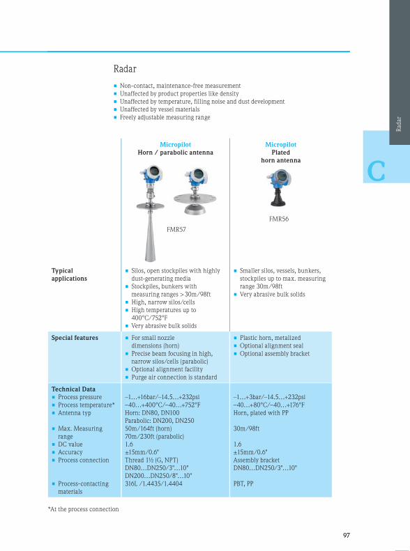
9797
C
Radar
• Non-contact, maintenance-free measurement
• Unaffected by product properties like density
• Unaffected by temperature, filling noise and dust development
• Unaffected by vessel materials
• Freely adjustable measuring range
Micropilot
Horn / parabolic antenna
Micropilot
Plated
horn antenna
Typical
applications
• Silos, open stockpiles with highly
dust-generating media
• Stockpiles, bunkers with
measuring ranges > 30m/98ft
• High, narrow silos/cells
• High temperatures up to
400°C/752°F
• Very abrasive bulk solids
• Smaller silos, vessels, bunkers,
stockpiles up to max. measuring
range 30m/98ft
• Very abrasive bulk solids
Special features • For small nozzle
dimensions (horn)
• Precise beam focusing in high,
narrow silos/cells (parabolic)
• Optional alignment facility
• Purge air connection is standard
• Plastic horn, metalized
• Optional alignment seal
• Optional assembly bracket
Technical Data
• Process pressure
• Process temperature*
• Antenna typ
• Max. Measuring
range
• DC value
• Accuracy
• Process connection
• Process-contacting
materials
–1…+16bar/–14.5…+232psi
–40…+400°C/–40…+752°F
Horn: DN80, DN100
Parabolic: DN200, DN250
50m/164ft (horn)
70m/230ft (parabolic)
1.6
±15mm/0.6"
Thread 1½ (G, NPT)
DN80…DN250/3"…10"
DN200…DN250/8"…10"
316L /1.4435/1.4404
–1…+3bar/–14.5…+232psi
–40…+80°C/–40…+176°F
Horn, plated with PP
30m/98ft
1.6
±15mm/0.6"
Assembly bracket
DN80…DN250/3"…10"
PBT, PP
*At the process connection
Rad
ar
FMR57
FMR56

9898
C
Installation instructions – radar
Installation
• Not centered [3]
• Not above filling curtain [4]
• Distance to the wall [1]: ~ 1/6 of vessel diameter, at least however
20cm/7.9"
Weather protection cover [2]
• Always recommended for installation outside (solar radiation and
rain)
Connection for purge air or plating
• Connection for purge air:
FMR57, already integrated. In case of strong dust generation,
clogging of the antenna is avoided. Not possible for FMR56
• Horn plating:
FMR57, FMR51, see accessories
FMR56, already integrated PP plating of the horn, avoids clogging
Baffles in vessels
• Make sure that baffles [1] like limit switches, struts, etc. are
not within the beam cone (see also the beam angle table in this
respect (next page))
• Symmetrically arranged baffles [2], e. g. discharge aids etc. may
impair measurements
Optimizing measures
• Size of antenna: The larger the antenna the smaller the beam angle
and the lower the interfering echoes
• Interference echo suppression: Electronic suppression of interfering
echoes optimizes the measurement
• Inclined installed metallic plates [3] disperse the radar signals and
reduce interfering echoes
Alignment
• Serves the avoidance of interfering reflection and improved
measurement since the measurement can be aligned to the angle
of repose
• An alignment of the instrument is recommended
FMR57, with optional alignment device
FMR56, FMR51 with optional alignment seal or assemble bracket
Variable alignment with optional alignment seal Assemble bracket
4. Instrument selection within the measuring principle

9999
C
Measurement in plastic vessels
If the external wall of the vessel consists of a non-
conductive material (e. g. GFK), microwaves may also
be reflected by external interfering sources, e. g.
• Metal lines/pipes
• Conductors
• Grids
Ensure during installation that the beam cone of
the radar instrument for bulk solids is free of any
interfering sources.
Beam angle
The beam angle is defined as the angle at which the energy density of the radar waves assumes half the value of
the max. energy density (3dB width).
Radar waves are also emitted outside of the beam cone and may be reflected by interfering sources.
Cone diameter W in dependence on the type of antenna, beam angle () and distance D.
Size of
antenna
FMR56
Horn antenna
80mm/3” 100mm/4”
Beam angle
10° 8°
Size of
antenna
FMR57
Horn antenna Parabolic antenna
80mm/3" 100mm/4" 200mm/8" 250mm/10"
Beam angle
10° 8° 4° 3.5°
Distance (D) Cone diameter (W)
80mm/3" 100mm/4" 200mm/8" 250mm/10"
5m/16ft 0.87m/2.8ft 0.70m/2.24ft 0.35m/1.12ft 0.3m/0.98ft
10m/32ft 1.75m/5.6ft 1.40m/4.48ft 0.70m/2.23ft 0.61m/2ft
15m/49ft 2.62m/8.57ft 2.10m/6.85ft 1.05m/3.42ft 0.92m/3.01ft
20m/65ft 3.50m/11.37ft 2.80m/9.09ft 1.40m/4.54ft 1.22m/4ft
30m/98ft 5.25m/17.15ft 4.20m/13.71ft 2.10m/6.84ft 1.83m/6ft
40m/131ft 7.00m/22.92ft 5.59m/18.32ft 2.79m/9.15ft 2.44m/8ft
50m/164ft 8.75m/28.7ft 6.99m/22.94ft 3.50m/11.45ft 3.06m/10.04ft
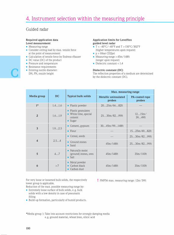
100100
C
4. Instrument selection within the measuring principle
Guided radar
Required application data
Level measurement
• Measuring range
• Consider ceiling load by max. tensile force
at the point of measurement
• Calculation of tensile force by Endress+Hauser
• DC value (DC) of the product
• Pressure and temperature
• Resistance requirements
• Existing nozzle diameter:
DN, PN, nozzle height
Application limits for Levelflex
guided level radar
• T < –40°C/–40°F and T > 150°C/302°F
(higher temperatures upon request)
• p > 16bar/232psi
• Measuring range > 45m/148ft
(longer upon request)
• Dielectric constant < 1.4
Dielectric constant (DC)
The reflection properties of a medium are determined
by the dielectric constant (DC).
Media group DC Typical bulk solids
Max. measuring range
Metallic uninsulated
probes
PA-coated rope
probes
1* 1.4…1.6 • Plastic powder 20…25m/66…82ft —
2 1.6…1.9
• Plastic granulates
• White lime, special
cement
• Sugar
25…30m/82…99ft12…15m/
39…49ft
3 1.9…2.5• Cement, gypsum 30…45m/99…148ft —
• Flour — 15…25m/49…82ft
4 2.5…4
• Cereal, seeds — 25…30m/82…99ft
• Ground stones
• Sand45m/148ft 25…30m/82…99ft
5 4…7
• Naturally moist
(ground) stones, ores
• Salt
45m/148ft 35m/110ft
6 > 7
• Metal powder
• Carbon black
• Carbon dust
45m/148ft 35m/110ft
*Media group 1: Take into account restrictions for strongly damping media
e. g. ground material, wheat bran, silicic acid
! FMP56 max. measuring range: 12m/39ftFor very loose or loosened bulk solids, the respectively
lower group is applicable.
Reduction of the max. possible measuring range by:
• Extremely loose surface of bulk solids, e. g. bulk
solids with a low density in case of pneumatic
filling
• Build-up formation, particularly of humid products.

101101
C
Guided radar
• Unaffected by product surface (e. g. angled surface)
• Unaffected by baffles in the silo
• Additional safety for measurements by EoP*1 evaluation
• Safe measurements also during filling
Levelflex Levelflex
Typical
applications
• Powdery solids
• Plastic granulates
• High and narrow silos
• Reflecting surfaces
• Powdery and grained bulk solids
• Plastic granulates
• High and narrow silos
• Reflecting surfaces
Special features • Exchangeable probes (rope)
• Coated rope probes (for cereal,
flour)
• Measurement during filling
• Exchangeable probes (rod, rope)
• Coated rope probes (for cereal,
flour)
• Measurement during filling
Technical Data
• Process pressure
• Process temperature*2
• Max. Measuring range
rope probe
rod probe
• DC value
• Accuracy
• Process connection
• Process-contacting materials
–1…+16bar/–14.5…+232psi
–40…+120°C/–40…+248°F
12m/39ft
—
1.4
< 15m/49ft: ±2mm/0.08";
> 15m/49ft: ±10mm/0.4"
¾" (G, NPT), adapter flange
304, 1.4301
–1…+16bar/–14.5…+580psi
–40…+150°C/–40…+302°F
45m/148ft
4m/13ft
1.4
< 15m/49ft: ±2mm/0.08";
> 15m/49ft: ±10mm/0.4"
1½" (G, NPT), flange
304, 1.4301
FMP56
*1 The patented End-of-Probe (EoP) algorithm enables Levelflex to provide accurate and reliable level
measurement in media with a low DC value (flour, cement, lime, PE granulates, PP granulates and various
powders) also during pneumatic filling and fluidized discharge
Gu
ided r
adar
*2 At the process connection
FMP57

102102
C
4. Instrument selection within the measuring principle
Installation instructions – guided radar
Probe selection
• Use rope probes for bulk solids in normal circumstances. Rod probes are only suited to short measuring ranges
up to approx. 2m/6.5ft in bulk solids. This is particularly true for applications in which the probe is installed
laterally and inclined and only for light and free-flowing bulk solids
• In case of large silos, the lateral load on the rope may be so high that a rope with a plastic jacket must be used.
We recommend a PA-coated rope for milled products like cereal, wheat and flour
Installation in concrete silos
• In concrete silos, the largest possible distance [B] of the probe to
the concrete wall - min. 0.5m/19.7" - is to be observed.
Optimum ≥ 1m/39"
• The installation into a concrete ceiling must be flush with its
bottom edge
Expansion of rope probes by tension and temperature
• 6mm/0.23" rope probe
- Elongation by tension: At max. permissible tensile load (30kN)
= 13mm (0.5")/m rope length
- Elongation by temperature increase from 30°C/86°F
to 150°C/302°F = 2mm (0.08")/m (ft) rope length
• 4mm/0.16" rope probe
- Elongation by tension: At max. permissible tensile load (12kN)
= 11mm (0.4")/m rope length
- Elongation by temperature increase from 30°C/86°F
to 150°C/302°F = 2mm (0.08")/m rope length
Installation
• Do not install rod and rope probes in the filling curtain [2]
• Install rod and rope probes at a distance to the wall [B], so that
in case of build-up on the wall a distance to the probe of at least
100mm/4" remains
• Install rod and rope probes with the largest possible distance to
baffles. In case of distances < 300mm/12", an interference echo
suppression must be included in commissioning
• When rod and rope probes are installed in plastic vessels, the
minimum distance of 300mm/12" is also applicable to metallic
parts outside of the vessel
• Rod and rope probes may not contact metal vessel walls or bottoms.
The minimum distance of the probe end to the bottom of the
vessel is applicable [C]: > 10mm/0.4".
For exceptions see the section “Fixation of rope probes”
• Avoid bending the rope probe sharply during installation or
operation (e. g. by product movements against the wall of the silo)
by the selection of a suitable point of installation
Weather protection cover [1]
• Always recommended for installation outside (solar radiation and
rain)
Metal
≥ 100mm/4" ≥ 100mm/4"
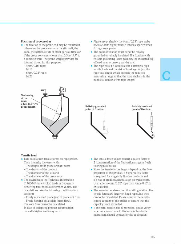
103103
C
Fixation of rope probes
• The fixation of the probe end may be required if
otherwise the probe contacts the silo wall, the
cone, the baffles/struts or other parts at times or
if the probe converges closer than 0.5m/19.7" to
a concrete wall. The probe weight provides an
internal thread for this purpose:
– 4mm/0.16" rope:
M 14
– 6mm/0.23" rope:
M 20
Tensile load
• Bulk solids exert tensile forces on rope probes.
Their intensity increases with:
– The length of the probe or max. cover
– The density of the product
– The diameter of the silo and
– The diameter of the probe rope
• The diagrams in the Technical Information
TI 01004F show typical loads in frequently
occurring bulk solids as reference values. The
calculations take the following conditions into
account:
– Freely suspended probe (end of probe not fixed)
– Freely flowing bulk solids (mass flow).
The core flow cannot be calculated.
In case of collapsing product accumulation
on walls higher loads may occur
• The tensile force values contain a safety factor of
2 (compensation of the fluctuation range in freely
flowing bulk solids)
• Since the tensile forces largely depend on the flow
properties of the product, a higher safety factor
is required for sluggishly flowing products and
if a risk of product accumulation on walls exists.
Use rather a 6mm/0.23" rope than 4mm/0.16" in
critical cases
• The same forces also act on the ceiling of silos. The
tensile forces are larger on fixed ropes, but they
cannot be calculated. Please observe the tensile-
loaded capacity of the probes or ensure that this
capacity is not exceeded
• If the max. tensile load is exceeded, please verify
whether a non-contact ultrasonic or level radar
instrument should be used for the application
• Please use preferably the 6mm/0.23" rope probe
because of its higher tensile-loaded capacity when
fixing a rope probe
• The point of fixation must either be reliably
grounded or reliably insulated. If a fixation with
reliable grounding is not possible, the insulated lug
offered as an accessory may be used
• The rope must be loose to avoid extremely high
tensile loads and the risk of breakage. Adjust the
rope to a length which exceeds the required
measuring range so that the rope slackens in the
middle ≥ 1cm (0.4")/m rope length!
Slackening
of the
rope:
≥ 1cm (0.4")/m
probe length Reliably insulated
point of fixation:
Reliably grounded
point of fixation:
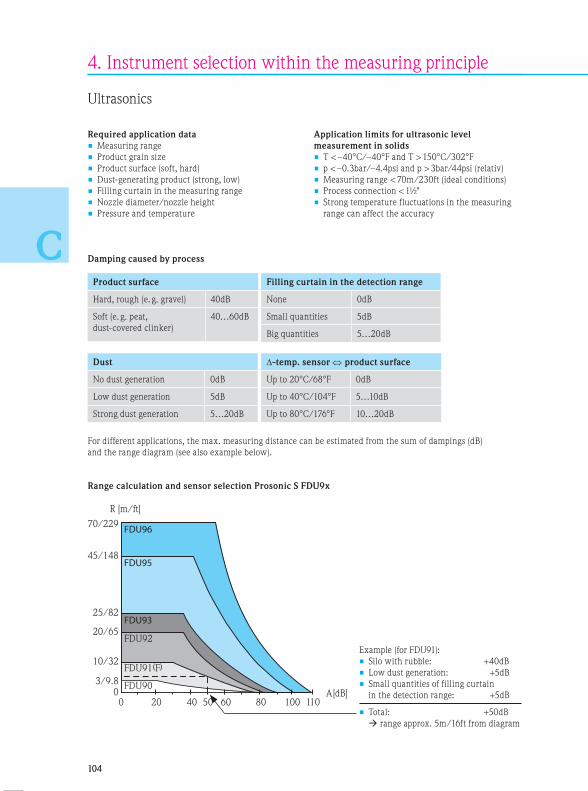
104104
C
4. Instrument selection within the measuring principle
Ultrasonics
Required application data
• Measuring range
• Product grain size
• Product surface (soft, hard)
• Dust-generating product (strong, low)
• Filling curtain in the measuring range
• Nozzle diameter/nozzle height
• Pressure and temperature
Application limits for ultrasonic level
measurement in solids
• T < –40°C/–40°F and T > 150°C/302°F
• p < –0.3bar/–4.4psi and p > 3bar/44psi (relativ)
• Measuring range < 70m/230ft (ideal conditions)
• Process connection < 1½"
• Strong temperature fluctuations in the measuring
range can affect the accuracy
Range calculation and sensor selection Prosonic S FDU9x
0 20 40 60 80 100 110
45/148
70/229
25/82
20/65
10/32
0
FDU95
FDU96
FDU93
FDU92
A[dB]
R [m/ft]
FDU903/9.8FDU91 F
50
( )
Example (for FDU91):
• Silo with rubble: +40dB
• Low dust generation: +5dB
• Small quantities of filling curtain
in the detection range: +5dB
• Total: +50dB
range approx. 5m/16ft from diagram
Damping caused by process
Product surface
Hard, rough (e. g. gravel) 40dB
Soft (e. g. peat,
dust-covered clinker)
40…60dB
For different applications, the max. measuring distance can be estimated from the sum of dampings (dB)
and the range diagram (see also example below).
Filling curtain in the detection range
None 0dB
Small quantities 5dB
Big quantities 5…20dB
Dust
No dust generation 0dB
Low dust generation 5dB
Strong dust generation 5…20dB
-temp. sensor product surface
Up to 20°C/68°F 0dB
Up to 40°C/104°F 5…10dB
Up to 80°C/176°F 10…20dB
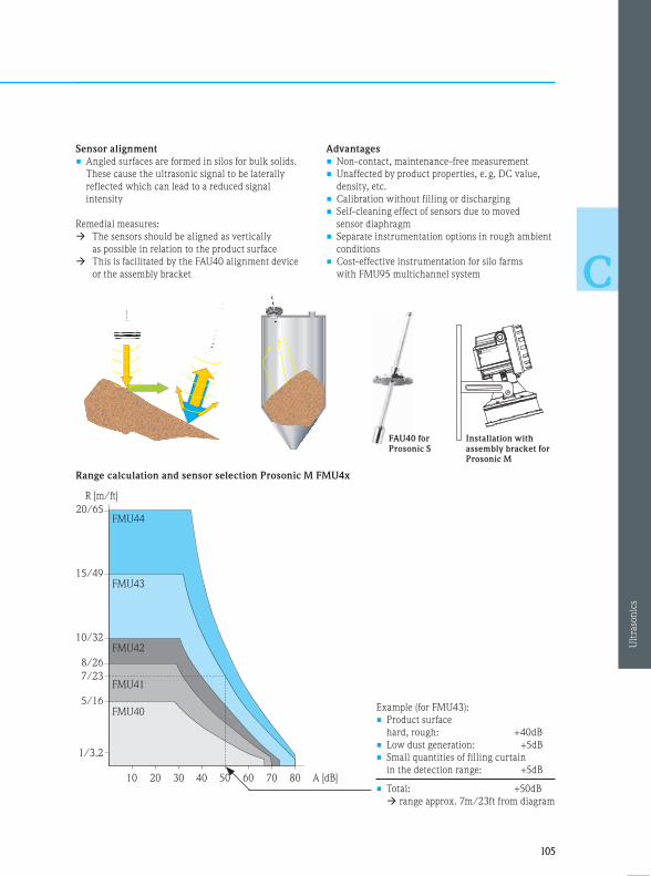
105105
C
Sensor alignment
• Angled surfaces are formed in silos for bulk solids.
These cause the ultrasonic signal to be laterally
reflected which can lead to a reduced signal
intensity
Remedial measures:
The sensors should be aligned as vertically
as possible in relation to the product surface
This is facilitated by the FAU40 alignment device
or the assembly bracket
Advantages
• Non-contact, maintenance-free measurement
• Unaffected by product properties, e. g. DC value,
density, etc.
• Calibration without filling or discharging
• Self-cleaning effect of sensors due to moved
sensor diaphragm
• Separate instrumentation options in rough ambient
conditions
• Cost-effective instrumentation for silo farms
with FMU95 multichannel system
Range calculation and sensor selection Prosonic M FMU4x
Example (for FMU43):
• Product surface
hard, rough: +40dB
• Low dust generation: +5dB
• Small quantities of filling curtain
in the detection range: +5dB
• Total: +50dB
range approx. 7m/23ft from diagram
Installation with
assembly bracket for
Prosonic M
FAU40 for
Prosonic S
Ult
raso
nic
s
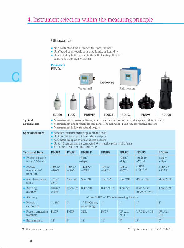
106106
C
4. Instrument selection within the measuring principle
Ultrasonics
• Non-contact and maintenance-free measurement
• Unaffected by dielectric constant, density or humidity
• Unaffected by build-up due to the self-cleaning effect of
sensors by diaphragm vibration
Prosonic S
FMU9x
FDU90 FDU91 FDU91F FDU92 FDU93 FDU95 FDU96
Typical
applications
• Measurement of coarse to fine-grained materials in silos, on belts, stockpiles and in crushers
• Measurement under rough process conditions (vibration, build-up, corrosion, abrasion)
• Measurement in low structural heights
Special features • Separate instrumentation up to 300m/984ft
• Up to 6 additional point level, alarm outputs
• Automatic recognition of connected sensors
• Up to 10 sensors can be connected attractive price in silo farms
• 4…20mA HART® or PROFIBUS® DP
Technical Data FDU90 FDU91 FDU91F FDU92 FDU93 FDU95 FDU96
• Process pressure
from -0.3/-4.4…
+3bar/
+44psi
+2bar/
+29psi
+0.5bar/
+7.2psi
+2bar/
+29psi
• Process
temperature*
from -40…
+80°C/
+176°F
+80°C/
+176°F
+105°C/
+221°F
+95°C/
+203°F
+95°C/
+203°F
+80°C/
+176°F *1
+150°C/
+302°F
• Max. Measuring
range
1.2m/
3.9ft
5m/16ft 5m/16ft 10m/32ft 15m/49ft 45m/150ft 70m/230ft
• Blocking
distance
0.07m/
0.23ft
0.3m/1ft 0.3m/1ft 0.4m/1.3 ft 0.6m/2ft 0.7m/2.3ft
(0.9m//2.9ft*1)
1.6m/5.2ft
• Accuracy ±2mm/0.08" +0.17% of measuring distance
• Process
connection
1", 1½" 1" 1”, Tri-Clamp,
collar flange
1" 1" 1" 1"
• Process-contacting
materials
PVDF PVDF 316L PVDF UP, Alu,
PTFE
UP, 316L*1, PE UP, Alu,
PTFE
• Beam angle 12° 9° 12° 11° 4° 5° 6°
FMU90/95
Field housingTop-hat rail
*At the process connection *1 High temperature = 150°C/302°F

107107
CProsonic M
FMU4x
FMU40 FMU41 FMU42 FMU43 FMU44
Typical
applications
• Measurement from coarse to fine-grained materials in recipient tanks, on belts at feed
points
• Measuring range up to 10m/32ft
Special features • Compact instrumentation (2 or 4-wire)
• Attractive price
• Robust aluminum housing
• 4..20mA HART®, PROFIBUS® PA or FF
Technical Data FMU40 FMU41 FMU42 FMU43 FMU44
• Process pressure –0.3…+2bar/–4.4…+29psi –0.3…+1.5bar/–4.4…+22psi
• Process
temperature*
–40…+80°C/–40…+176°F
• Measuring range
(solid)
2m/6ft 3.5m/11ft 5m/16ft 7m/22ft 10m/32ft
• Blocking distance 0.25m/0.8ft 0.35m/1.15ft 0.4m/1.3ft 0.6m/2ft 0.5m/1.6ft
• Accuracy ±2mm/0.08" o. 0.2% of
measuring distance*2
±4mm/0.15" of 0.2% of measuring distance*2
• Process
connection
1.5" 2" DN80/3";
DN100/4";
DN150/6"
assembly bracket
DN100/4";
DN150/6";
DN200/8"
assembly bracket
DN100/4";
DN150/6";
DN200/8"
assembly bracket
• Process-
contacting
materials
PVDF
EPDM
PVDF
EPDM
PVDF
EPDM o. Viton,
flange PP, PVDF,
316L
UP/316L, EPDM,
flange PP, PVDF,
316L
PVDF
EPDM o. Viton,
flange PP, 316L
• Beam angle 11° 11° 9° 6° 11°
*2 The higher value is applicable*At the process connection

108108
C
4. Instrument selection within the measuring principle
Installation instructions – ultrasonics
Installation
• Not centered [3]
• Not above filling curtain [4]
• Distance to wall: ~ 1/6 of the vessel diameter, at least however
20cm/7.9" [1]
• If 2 or several sensors are used in one vessel, please use separate
instrumentation (FMU90/95 + FDU9x)
Weather protection cover [2]
• Always recommended for installation outside (solar radiation and
rain) – Prosonic M
Nozzle
• The sensor diaphragm should protrude from the nozzle. If this is
not possible, please compare the dimensions of the nozzle with the
table: Nozzle length (next page)
Measuring range
• Measurement is possible up to the blocking distance (BD) on principle
• The measuring range starts where the ultrasonic lobe meets the
bottom of the silo. In dished or torispherical heads or conical
outlets, levels below this point cannot be detected
Silo baffles
• Make sure that baffles [1] like limit switches, struts, etc. are
not within the beam cone (see also the beam angle table in this
respect [)• Symmetrically arranged baffles [2], e. g. discharge aids etc. may
impair measurements
Optimizing measures
• Use a sensor with a smaller beam angle. The smaller the beam
angle the lower the occurrence of interfering echoes
• Interference echo suppression: Electronic suppression of interfering
echoes optimizes the measurement
• Plates installed in an inclined manner [3] disperse the signal and
can avoid interfering echoes
Alignment
• Serves the avoidance of interfering reflections and improved
measurements since the measurement can be aligned to the
angled surface (accessory FAU40 or assembly bracket)
FMU40 FMU41 FMU42 FMU43 FMU44 FDU90 FDU91 FDU91F FDU92 FDU93 FDU95 FDU96
Beam
angle 11° 11° 9° 6° 11° 12° 9° 12° 11° 4° 5° 6°
Lmax (m/ft) 2/6 3.5/11 5/16 7/22 10/32 1.2/3.9 5/16 5/16 10/32 15/49 45/150 70/230
rmax (m/ft) 0.19/0.6 0.34/1.1 0.39/1.3 0.37/1.2 1.96/6.4 0.13/0.4 0.39/1.3 0.53/1.7 0.96/3.1 0.52/1.7 1.96/6.4 3.6/11.8
Blocking
distance
(m/ft)
0.25/
0.8
0.35/
1.15
0.4/
1.3
0.6/
2
0.5/
1.6
0.07/
0.23
0.3/
1
0.3/
1
0.4/
1.3
0.6/
2
0.7/2.3
(0.9/
2.9*)
1.6/
5.2
*High temperature = 150°C/302°F

109109
C
Nozzle
øMax. nozzle length in mm/inch (L)
FMU40 FMU41 FMU42 FMU43 FMU44 FDU90 FDU91 FDU91F FDU92 FDU93 FDU95 FDU96
DN50/2" 80/3.15 502)/1.972)
DN80/3" 240/
9.45
240/
9.45
250/
9.84
3901), 2502)/
15.41), 9.842)
340/
13.4
250/
9.84*
DN100/4" 300/
11.8
300/
11.8
300/
11.8
300/
11.8
3901), 3002)/
15.41), 11.82)
390/
15.4
300/
11.8*
DN150/6" 400/
15.8
400/
15.8
400/
15.8
300/
11.8
400/
15.8
4001), 3002)/
15.81), 11.82)
400/
15.8
300/
11.8*
400/
15.8
DN200/8" 400/
15.8
400/
15.8
400/
15.8
300/
11.8
400/
15.8
4001), 3002)/
15.81), 11.82)
400/
15.8
300/
11.8*
400/
15.8
520/
20.5
DN250/10" 400/
15.8
400/
15.8
400/
15.8
300/
11.8
400/
15.8
4001), 3002)/
15.81), 11.82)
400/
15.8
300/
11.8*
400/
15.8
520/
20.5
630/
24.8
DN300/12" 400/
15.8
400/
15.8
400/
15.8
300/
11.8
400/
15.8
4001), 3002)/
15.81), 11.82)
400/
15.8
300/
11.8*
400/
15.8
520/
20.5
630/
24.8
800/
31.5
Beam
angle 11° 11° 11° 6° 11° 12° 9° 12° 11° 4° 5° 6°
Blocking
distance
(m/ft)
0.25/
0.8
0.35/
1.15
0.4/
1.3
0.6/
2
0.5/
1.6
0.07/
0.23
0.3/
1
0.3/
1
0.4/
1.3
0.6/
2
0.7/
2.3
1.6/
5.2
Options for installation
Prosonic M FMU4x
* Applicable to flush flange installation, for assembly via G/NPT 1” starting DN100 see FDU911) Mounted at backside thread of the Sensor FDU902) Mounted at frontside thread of the Sensor FDU90
Prosonic S FDU9xFDU9x FDU91F
Universal flange installation Assembly bracket installation
e.g. Zone 20
FDU901) FDU902)

110110
C
4. Instrument selection within the measuring principle
Electromechanical level system
Required application data
• Measuring range
• Consider ceiling load by max. tensile
force at the point of measurement
• Product grain size
• Pressure and temperature
• Resistance requirements
• Nozzle height
Application limits for the
electromechanical level system
• T < –20°C/–4°F or T > 230°C/446°F
• p > 2bar/29psi
• Measuring range > 70m/230ft
• Tensile force > 500N
Model Sensing weight Application Temperature Materials Weig
FMM50 Normal weight, cylindrical
with removable spike
Coarse bulk solids, e. g. coal,
ore or stones and granulates
Complete
temperature range
Steel,
stainless steel
3.5kg
FMM50 Umbrella weight Very light and loose bulk solids,
e. g. flour or carbon dust
Max. 150°C/302°F Steel or
stainless steel
with Polyester
3.5kg
FMM50 Bag weight Bunkers with mills downstream Max. 150°C/302°F Bag made of
Polyester,
stainless steel
0.25k
3.5kg
FMM50 Cage weight Fine-grained bulk solids Complete
temperature range
Steel,
stainless steel
3.5kg
FMM50 Oval float Granulates Max. 70°C/158°F Rigid PVC 3.5kg
FMM50 Bell weight Light and loose bulk solids Complete
temperature range
Steel,
stainless steell
4.3kg
FMM20 Normal weight, cylindrical
with removable spike
Granulates and compacted bulk
solids
Max. 150°C/302°F Steel,
stainless steel
1.5kg
FMM20 Normal weight, cylindrical Granulates and compacted bulk
solids
Max. 70°C/158°F Plastics 1.5kg
FMM20 Umbrella weight Very light and loose bulk solids,
e. g. flour or carbon dust
Max. 150°C/302°F Steel or
stainless steel
with polyester
1.5kg
FMM20 Bag weight Bunkers with mills downstream Max. 150°C/302°F Polyester,
stainless steel
0.25k
1.5kg
Recommendation concerning the selection
The following aspects should be observed in the selection of the sensing weight:
• The sensing weight may neither sink into the product nor slide off the angled surface during the measuring
operation
• The sensing weight must be able to withstand the chemical properties of the product and the temperature
prevailing in the bunker/silo
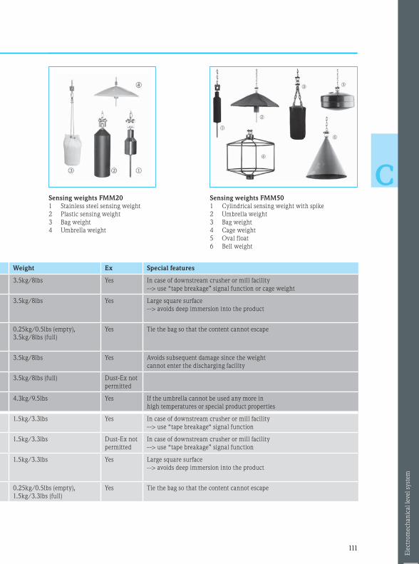
111111
C
Weight Ex Special features
teel
3.5kg/8lbs Yes In case of downstream crusher or mill facility
--> use “tape breakage” signal function or cage weight
teel
ster
3.5kg/8lbs Yes Large square surface
--> avoids deep immersion into the product
of
teel
0.25kg/0.5lbs (empty),
3.5kg/8lbs (full)
Yes Tie the bag so that the content cannot escape
teel
3.5kg/8lbs Yes Avoids subsequent damage since the weight
cannot enter the discharging facility
3.5kg/8lbs (full) Dust-Ex not
permitted
teell
4.3kg/9.5lbs Yes If the umbrella cannot be used any more in
high temperatures or special product properties
teel
1.5kg/3.3lbs Yes In case of downstream crusher or mill facility
--> use “tape breakage“ signal function
1.5kg/3.3lbs Dust-Ex not
permitted
In case of downstream crusher or mill facility
--> use “tape breakage” signal function
teel
ster
1.5kg/3.3lbs Yes Large square surface
--> avoids deep immersion into the product
teel
0.25kg/0.5lbs (empty),
1.5kg/3.3lbs (full)
Yes Tie the bag so that the content cannot escape
Sensing weights FMM20
1 Stainless steel sensing weight
2 Plastic sensing weight
3 Bag weight
4 Umbrella weight
Sensing weights FMM50
1 Cylindrical sensing weight with spike
2 Umbrella weight
3 Bag weight
4 Cage weight
5 Oval float
6 Bell weight
Ele
ctro
mech
an
ical le
vel
syst
em

112112
CSilopilot M
FMM50
Silopilot T
FMM20
Typical
applications
• Bunkers and silos with powdery,
fine-grained or coarse-grained bulk
solids
• Bunkers and silos for light
• bulk solids, e. g. cereals,
• plastics granulate, powder
Special features • Easy commissioning • Easy commissioning
Technical data
• Process pressure
• Process temperature*
• Max. measuring range
• Accuracy
• Tensile force
• Process connection
• Process-contacting
material
• Ambient temperature
• Electronics
• Approvals
• Ingress protection
–0.2…+2bar/–3…+29psi
–20…+230°C/–4…+446°F
70m/230ft
±5cm/±2" or ±1 pulse
Max. 500N
On counterflange DN100 PN16
Alu, steel or stainless steel
(301 modified, 304, 316, 316TI),
Nomex, PVC
–40…+70°C/–40…+158°F
4…20mA / relay
ATEX II 1/2D
IP67
–0.2…+2bar/–3…+29psi
–20…+150°C/–4…+302°F
32m/105ft
±2.5cm/±1" or. ±1 pulse
Max. 150N
On counterflange DN100 PN16
Alu, steel or stainless steel
(301 modified, 304, 316, 316TI)
plastic, polyester
–40…+60°C/–40…+140°F
0/4…20mA / relay
ATEX II 1/2D
IP67
4. Instrument selection within the measuring principle
Electromechanical level system
• Unaffected by product properties
• Light bulk solids
• Unaffected by DC value
*At the process connection

113113
C
Installation
• Not in the filling curtain or in the area of collapsing
product accumulation on walls
• Measuring point as close to the center of the slope
as possible
• The sensing weight may neither sink into the
product nor slide off the angled surface during the
measuring operation
• Max. angle of inclination 2°
Weather protection cover
• Always recommended for installation outside (solar
radiation and rain)
Compressed air connection
• Already integrated and the penetration of dust can
be avoided in case of strong dust generation
Tank baffles
• The measurement section should not pass baffles
and struts at too close a distance. The measuring
tape must not touch any baffles and struts
Filling position
Distance Distance
*1
100 %
X %
Y %
0 %
Angle surface
Slope
Outflow funnel
*2
*2
*1 Accumulation (product build-up on the wall
of the vessel)
*2 Choose a measuring point located approximately
in the middle of the slope
Installation instructions – electromechanical level system

Notes
114114
C

Notes
115115
C

www.addresses.endress.comCP
000
23F/
00/E
N/1
4.12
Applicator Selection SoftwareProduct selection guidewww.endress.com/applicator