Continuous extrusion and rolling forming of copper strips … · ducts a hot rolling process using...
6
Continuous extrusion and rolling forming of copper strips Xinbing Yun * , Mo Zhou, Tian Tian, and Ying Zhao Engineering Research Center of Continuous Extrusion, Ministry of Education, Dalian Jiaotong University, Dalian 116028, P.R. China Received 25 September 2015 / Accepted 5 February 2016 Abstract – Continuous extrusion and rolling technology was proposed as a new strip production technology. It con- ducts a hot rolling process using waste heat after continuous extrusion. The continuous extrusion and rolling forming was simulated with DEFORM-3D T . Influences of extrusion wheel velocity and rolling reduction on the continuous extrusion and rolling forming were analyzed. It was shown that as extrusion wheel velocity increases, torque of extru- sion wheel, chamber force and rolling force, will drop; temperature of the billet in the area of abutment which is high- est will increase. As the rolling reduction is increased, torque of the extrusion wheel and force acting on the chamber decrease, while torque and force of the rolls increase. The experimental results showed that a homogeneously distrib- uted and equiaxed grains microstructure can be formed in copper strip billets with an average grain size of about 80 lm, after continuous extrusion. Grains of the copper strips are stretched clearly, during rolling, along the rolling direction, to form a stable orientation. Nevertheless, the grain boundaries are still relatively clear to see. Key words: Continuous extrusion and rolling, Copper strip, Numerical simulation, Rolling reduction 1. Introduction Continuous extrusion and rolling forming technology is a burgeoning and environmental manufacturing technology. It is combined with continuous extrusion process and rolling pro- cess in a row. The principle of continuous extrusion and rolling process is that oxygen-free copper plates or strips is pressed in the groove of the extrusion wheel by coining wheel, and moves with the friction of extrusion wheel rotating, then is obstructed by the abutment, turns to the chamber. The billet fills the cham- ber until extruded from the die. The temperature of the strips from continuous extrusion is about 400–600 °C in the exit of die [1], there is a distance between continuous extrusion machine and rolling mill, and strips supplied by continuous extrusion could be rolled down until reaching a certain length with the temperature about 360–400 °C in the entrance of rolls. Compared to traditional processes of cold rolling after con- tinuous extrusion, the continuous extrusion and rolling process method has the following advantages [2–5]: (1) In this process, the frictional resistance for energy dissipation is transferred into the deformation driving force, and deformation heat and friction heat are used to reach the thermal deformation temper- ature of billet, so the heating process is eliminated; and (2) both the continuous extrusion and rolling completely achieve the thermal deformation of the billet, during which the dynamic recrystallization occurs. Therefore, the grain is significantly refined and the material property is improved; however, the size of the billet is nearly the same as that of the finished prod- uct, thus reducing the workforce of the finishing process. Yun et al. proposed the principle of continuous extrusion and rolling technology, based on theoretical calculation and numerical simulation [6]. But it did not consider the metal flow regularity in the process with variation of the technological parameter. In this work, the finite element model of continuous extru- sion and rolling process was established by using DEFORM- 3D software platform in order to simulate the whole process, and the metal flow regularity was analyzed in the continuous extrusion and rolling process with variation of the technologi- cal parameter, such as the influence of extrusion wheel veloc- ity, rolling reduction and strip size. 2. Numerical simulation of continuous extrusion and rolling The DEFORM-3D software was used for the numerical simulation of continuous extrusion and rolling process of cop- per strips. The influence of extrusion wheel velocity and rolling reduction on the continuous extrusion and rolling forming pro- cess were analyzed. The temperature of billet, effective-stress of billet, torques of extrusion wheel and rolls, force of cham- ber, rolling force were compared and studied during forming. *Corresponding author: [email protected] Manufacturing Rev. 2016, 3,7 Ó X. Yun et al., Published by EDP Sciences, 2016 DOI: 10.1051/mfreview/2016007 Available online at: http://mfr.edp-open.org This is an Open Access article distributed under the terms of the Creative Commons Attribution License (http://creativecommons.org/licenses/by/4.0), which permits unrestricted use, distribution, and reproduction in any medium, provided the original work is properly cited. OPEN ACCESS RESEARCH ARTICLE
-
Upload
vuongduong -
Category
Documents
-
view
227 -
download
1
Transcript of Continuous extrusion and rolling forming of copper strips … · ducts a hot rolling process using...

Continuous extrusion and rolling forming of copper strips
Xinbing Yun*, Mo Zhou, Tian Tian, and Ying Zhao
Engineering Research Center of Continuous Extrusion, Ministry of Education, Dalian Jiaotong University, Dalian 116028, P.R. China
Received 25 September 2015 / Accepted 5 February 2016
Abstract – Continuous extrusion and rolling technology was proposed as a new strip production technology. It con-ducts a hot rolling process using waste heat after continuous extrusion. The continuous extrusion and rolling formingwas simulated with DEFORM-3DT. Influences of extrusion wheel velocity and rolling reduction on the continuousextrusion and rolling forming were analyzed. It was shown that as extrusion wheel velocity increases, torque of extru-sion wheel, chamber force and rolling force, will drop; temperature of the billet in the area of abutment which is high-est will increase. As the rolling reduction is increased, torque of the extrusion wheel and force acting on the chamberdecrease, while torque and force of the rolls increase. The experimental results showed that a homogeneously distrib-uted and equiaxed grains microstructure can be formed in copper strip billets with an average grain size of about80 lm, after continuous extrusion. Grains of the copper strips are stretched clearly, during rolling, along the rollingdirection, to form a stable orientation. Nevertheless, the grain boundaries are still relatively clear to see.
Key words: Continuous extrusion and rolling, Copper strip, Numerical simulation, Rolling reduction
1. Introduction
Continuous extrusion and rolling forming technology is aburgeoning and environmental manufacturing technology. Itis combined with continuous extrusion process and rolling pro-cess in a row. The principle of continuous extrusion and rollingprocess is that oxygen-free copper plates or strips is pressed inthe groove of the extrusion wheel by coining wheel, and moveswith the friction of extrusion wheel rotating, then is obstructedby the abutment, turns to the chamber. The billet fills the cham-ber until extruded from the die. The temperature of the stripsfrom continuous extrusion is about 400–600 �C in the exit ofdie [1], there is a distance between continuous extrusionmachine and rolling mill, and strips supplied by continuousextrusion could be rolled down until reaching a certain lengthwith the temperature about 360–400 �C in the entrance ofrolls.
Compared to traditional processes of cold rolling after con-tinuous extrusion, the continuous extrusion and rolling processmethod has the following advantages [2–5]: (1) In this process,the frictional resistance for energy dissipation is transferredinto the deformation driving force, and deformation heat andfriction heat are used to reach the thermal deformation temper-ature of billet, so the heating process is eliminated; and (2) boththe continuous extrusion and rolling completely achieve thethermal deformation of the billet, during which the dynamic
recrystallization occurs. Therefore, the grain is significantlyrefined and the material property is improved; however, thesize of the billet is nearly the same as that of the finished prod-uct, thus reducing the workforce of the finishing process.
Yun et al. proposed the principle of continuous extrusionand rolling technology, based on theoretical calculation andnumerical simulation [6]. But it did not consider the metal flowregularity in the process with variation of the technologicalparameter.
In this work, the finite element model of continuous extru-sion and rolling process was established by using DEFORM-3D software platform in order to simulate the whole process,and the metal flow regularity was analyzed in the continuousextrusion and rolling process with variation of the technologi-cal parameter, such as the influence of extrusion wheel veloc-ity, rolling reduction and strip size.
2. Numerical simulation of continuousextrusion and rolling
The DEFORM-3D software was used for the numericalsimulation of continuous extrusion and rolling process of cop-per strips. The influence of extrusion wheel velocity and rollingreduction on the continuous extrusion and rolling forming pro-cess were analyzed. The temperature of billet, effective-stressof billet, torques of extrusion wheel and rolls, force of cham-ber, rolling force were compared and studied during forming.*Corresponding author: [email protected]
Manufacturing Rev. 2016, 3, 7� X. Yun et al., Published by EDP Sciences, 2016DOI: 10.1051/mfreview/2016007
Available online at:http://mfr.edp-open.org
This is an Open Access article distributed under the terms of the Creative Commons Attribution License (http://creativecommons.org/licenses/by/4.0),which permits unrestricted use, distribution, and reproduction in any medium, provided the original work is properly cited.
OPEN ACCESSRESEARCH ARTICLE
The size of a copper strip produced by continuous extrusionprocess is depicted in Figure 1.
The finite element simulation model which was establishedby using TLJ400 continuous extrusion machine and the rollwith diameter of 250 mm as the model is depicted in Figure 2,where the representative geometry parameters are indicated. Tosave time and reduce the computer storage capacity, 1/2 of theintegral model was used for the simulations based on the sym-metry [7, 8].
In this work, the rigid viscoplastic finite element methodwas used. The billet was set as the rigid-plastic body, whereasthe die and other parts were set as rigid bodies. The shear fric-tion driving model was used for the friction between the contactsurfaces of the billet and the die. All of the initial parameters innumerical simulation are shown in Table 1 [9–12].
3. Simulation results and analysis
3.1 Influences of the extrusion wheel velocity onthe continuous extrusion and rolling forming
Extrusion wheel velocity was set to 6 r/min, 9 r/min,12 r/min for the numerical simulations. Comparison of temper-ature, effective-stress, torque of extrusion wheel and rolling,force of chamber, and rolling force are analysed in differentextrusion wheel velocity.
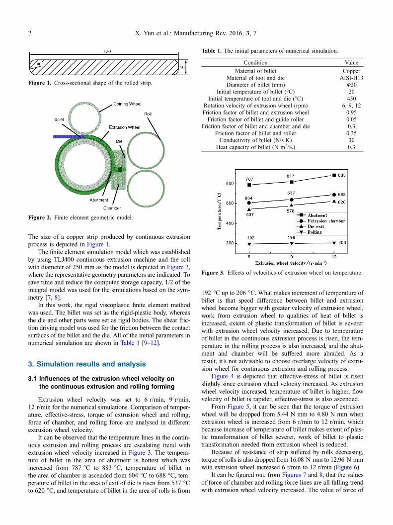
It can be observed that the temperature lines in the contin-uous extrusion and rolling process are escalating trend withextrusion wheel velocity increased in Figure 3. The tempera-ture of billet in the area of abutment is hottest which wasincreased from 787 �C to 883 �C, temperature of billet inthe area of chamber is ascended from 604 �C to 688 �C, tem-perature of billet in the area of exit of die is risen from 537 �Cto 620 �C, and temperature of billet in the area of rolls is from
192 �C up to 206 �C. What makes increment of temperature ofbillet is that speed difference between billet and extrusionwheel become bigger with greater velocity of extrusion wheel,work from extrusion wheel to qualities of heat of billet isincreased, extent of plastic transformation of billet is severerwith extrusion wheel velocity increased. Due to temperatureof billet in the continuous extrusion process is risen, the tem-perature in the rolling process is also increased, and the abut-ment and chamber will be suffered more abraded. As aresult, it’s not advisable to choose overlarge velocity of extru-sion wheel for continuous extrusion and rolling process.
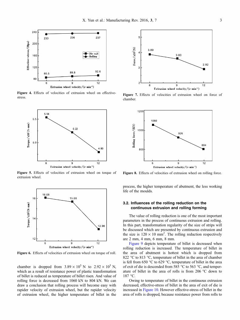
Figure 4 is depicted that effective-stress of billet is risenslightly since extrusion wheel velocity increased. As extrusionwheel velocity increased, temperature of billet is higher, flowvelocity of billet is rapider, effective-stress is also ascended.
From Figure 5, it can be seen that the torque of extrusionwheel will be dropped from 5.44 N mm to 4.80 N mm whenextrusion wheel is increased from 6 r/min to 12 r/min, whichbecause increase of temperature of billet makes extent of plas-tic transformation of billet severer, work of billet to plastictransformation needed from extrusion wheel is reduced.
Because of resistance of strip suffered by rolls decreasing,torque of rolls is also dropped from 16.08 N mm to 12.96 N mmwith extrusion wheel increased 6 r/min to 12 r/min (Figure 6).
It can be figured out, from Figures 7 and 8, that the valuesof force of chamber and rolling force lines are all falling trendwith extrusion wheel velocity increased. The value of force of
Figure 1. Cross-sectional shape of the rolled strip.
Figure 2. Finite element geometric model.
Table 1. The initial parameters of numerical simulation.
Condition Value
Material of billet CopperMaterial of tool and die AISI-H13Diameter of billet (mm) U20
Initial temperature of billet (�C) 20Initial temperature of tool and die (�C) 450
Rotation velocity of extrusion wheel (rpm) 6, 9, 12Friction factor of billet and extrusion wheel 0.95
Friction factor of billet and guide roller 0.05Friction factor of billet and chamber and die 0.3
Friction factor of billet and roller 0.35Conductivity of billet (N/s K) 30
Heat capacity of billet (N m2/K) 0.3
Figure 3. Effects of velocities of extrusion wheel on temperature.
2 X. Yun et al.: Manufacturing Rev. 2016, 3, 7
chamber is dropped from 3.89 · 105 N to 2.92 · 105 N,which as a result of resistance power of plastic transformationof billet is reduced as temperature of billet risen. And value ofrolling force is decreased from 1060 kN to 804 kN. We candraw a conclusion that rolling process will become easy withrapider velocity of extrusion wheel, but the rapider velocityof extrusion wheel, the higher temperature of billet in the
process, the higher temperature of abutment, the less workinglife of the moulds.
3.2. Influences of the rolling reduction on thecontinuous extrusion and rolling forming
The value of rolling reduction is one of the most importantparameters in the process of continuous extrusion and rolling.In this part, transformation regularity of the size of strips willbe discussed which are presented by continuous extrusion andthe size is 120 · 10 mm2. The rolling reduction respectivelyare 2 mm, 4 mm, 6 mm, 8 mm.
Figure 9 depicts temperature of billet is decreased whenrolling reduction is increased. The temperature of billet inthe area of abutment is hottest which is dropped from822 �C to 813 �C, temperature of billet in the area of chamberis fell from 650 �C to 629 �C, temperature of billet in the areaof exit of die is descended from 585 �C to 563 �C, and temper-ature of billet in the area of rolls is from 206 �C down to187 �C.
Owing to temperature of billet in the continuous extrusiondecreased, effective-stress of billet in the area of exit of die isincreased in Figure 10. However effective-stress of billet in thearea of rolls is dropped, because resistance power from rolls to
Figure 4. Effects of velocities of extrusion wheel on effective-stress.
Figure 5. Effects of velocities of extrusion wheel on torque ofextrusion wheel.
Figure 6. Effects of velocities of extrusion wheel on torque of roll.
Figure 7. Effects of velocities of extrusion wheel on force ofchamber.
Figure 8. Effects of velocities of extrusion wheel on rolling force.
X. Yun et al.: Manufacturing Rev. 2016, 3, 7 3
billet is reduced as reduction decreased, which makes billetflowing harder and more slowly.
It can be obviously observed that value of torque of extru-sion wheel and force of chamber is declined at first, thenascended following in Figures 11 and 12. When rolling reduc-tion is from 2 mm up to 4 mm, torque of extrusion wheel isdescended from 5.47 N mm to 5.18 N mm, and force ofchamber is from 4.79 · 105 N to 3.15 · 105 N. When rollingreduction is from 4 mm up to 8 mm, torque of extrusion wheel
is increased from 5.18 N mm to 5.70 N mm, and force ofchamber is from 3.15 · 105 N to 4.83 · 105 N.
While value of torque and stress of rolls are risen accom-panied by rolling reduction increased. Torque of rolls inFigure 13 is increased from 4.52 N mm to 18.36 N mm, asrolling reduction increasing from 2 mm to 8 mm. At the sametime, force of rolls in Figure 14 are risen from 465 kN to1148 kN. In other words, it is not suitable for rolling processto take overlarge rolling reduction, if not, service life of rollswill be influenced.
Figure 9. Effects of rolling reduction on temperature.
Figure 10. Effects of rolling reduction on effective-stress.
Figure 11. Effects of rolling reduction on torque of extrusionwheel.
Figure 12. Effects of rolling reduction on force of chamber.
Figure 13. Effects of rolling reduction on torque of roll.
Figure 14. Effects of rolling reduction on rolling force.
4 X. Yun et al.: Manufacturing Rev. 2016, 3, 7
4. Experiment
4.1. Experimental procedures
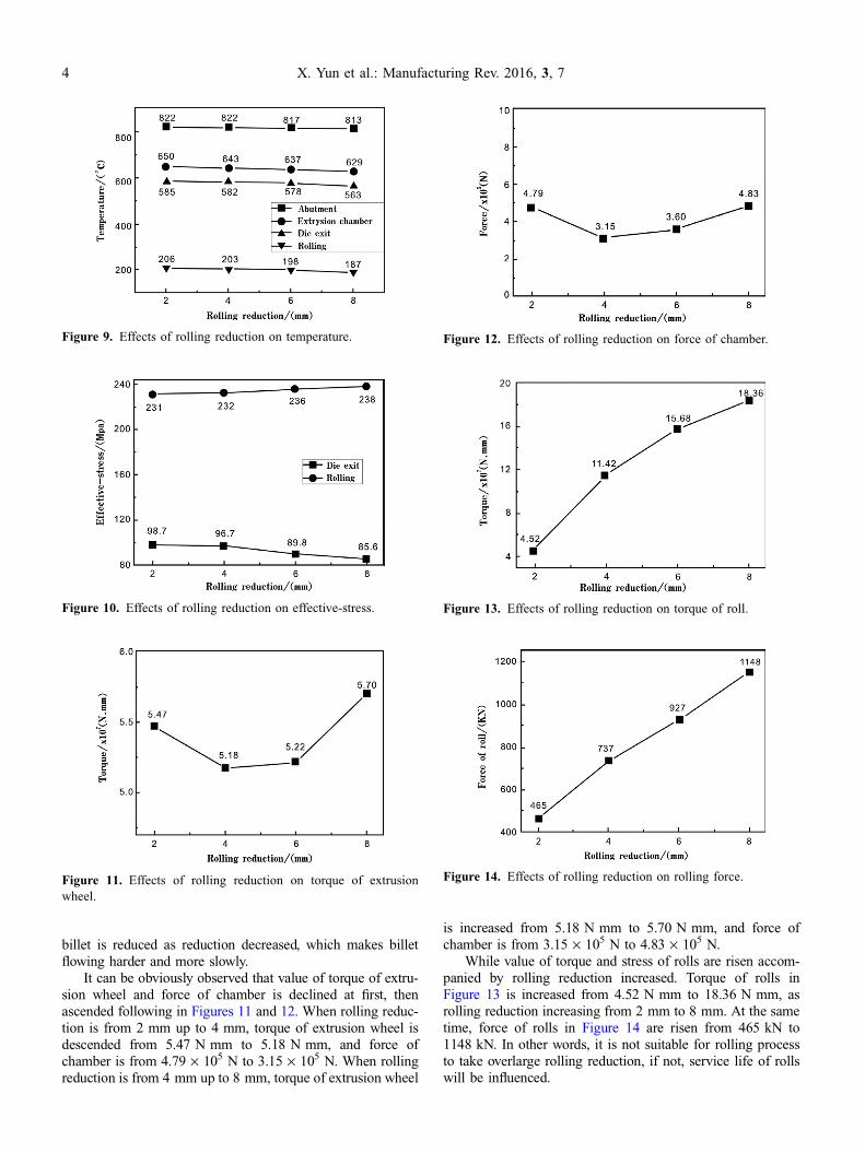
In the experiment, TLJ400 continuous extrusion machineand rolling mill with a diameter of 250 mm were used for con-tinuous extrusion and rolling process, (Figure 15). The wheelspeed was 5 rpm, the size of extrusion slab was120 mm · 10 mm and the rolling reduction was 4 mm.
The specimens in extrusion wheel groove, deformationchamber, after extrusion and after rolling were taken out andprepared by wire cutting along the longitudinal direction.Metallographic specimens were corroded by compositing acid(FeCl3+HCl) after furbishing and polishing. Microstructureswere observed under the OLYMPUS BX41M metalloscope.
4.2. Results and discussion
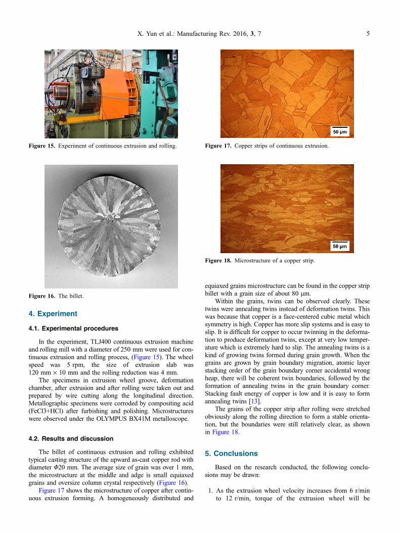
The billet of continuous extrusion and rolling exhibitedtypical casting structure of the upward as-cast copper rod withdiameter U20 mm. The average size of grain was over 1 mm,the microstructure at the middle and adge is small equiaxedgrains and oversize column crystal respectively (Figure 16).
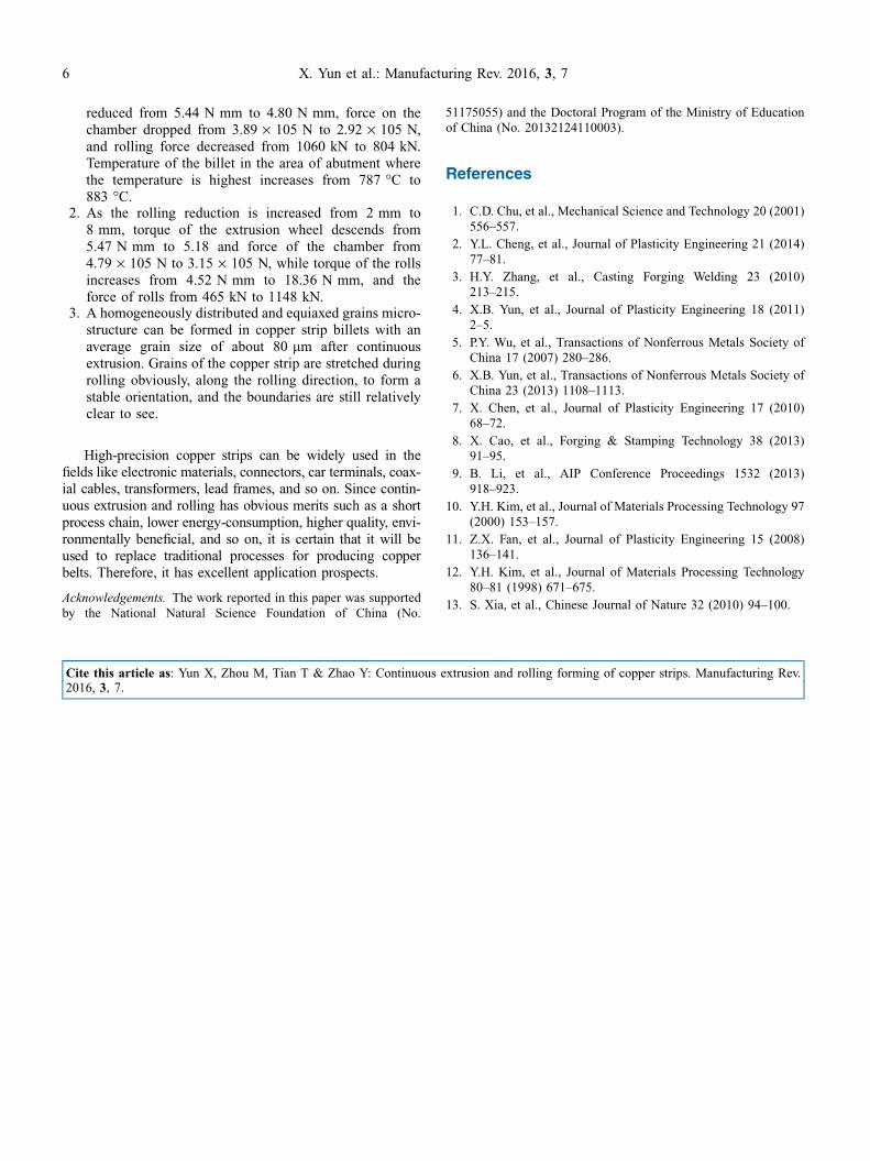
Figure 17 shows the microstructure of copper after contin-uous extrusion forming. A homogeneously distributed and
equiaxed grains microstructure can be found in the copper stripbillet with a grain size of about 80 lm.
Within the grains, twins can be observed clearly. Thesetwins were annealing twins instead of deformation twins. Thiswas because that copper is a face-centered cubic metal whichsymmetry is high. Copper has more slip systems and is easy toslip. It is difficult for copper to occur twinning in the deforma-tion to produce deformation twins, except at very low temper-ature which is extremely hard to slip. The annealing twins is akind of growing twins formed during grain growth. When thegrains are grown by grain boundary migration, atomic layerstacking order of the grain boundary corner accidental wrongheap, there will be coherent twin boundaries, followed by theformation of annealing twins in the grain boundary corner.Stacking fault energy of copper is low and it is easy to formannealing twins [13].
The grains of the copper strip after rolling were stretchedobviously along the rolling direction to form a stable orienta-tion, but the boundaries were still relatively clear, as shownin Figure 18.
5. Conclusions
Based on the research conducted, the following conclu-sions may be drawn:
1. As the extrusion wheel velocity increases from 6 r/minto 12 r/min, torque of the extrusion wheel will be
Figure 15. Experiment of continuous extrusion and rolling.
Figure 16. The billet.
Figure 17. Copper strips of continuous extrusion.
Figure 18. Microstructure of a copper strip.
X. Yun et al.: Manufacturing Rev. 2016, 3, 7 5
reduced from 5.44 N mm to 4.80 N mm, force on thechamber dropped from 3.89 · 105 N to 2.92 · 105 N,and rolling force decreased from 1060 kN to 804 kN.Temperature of the billet in the area of abutment wherethe temperature is highest increases from 787 �C to883 �C.
2. As the rolling reduction is increased from 2 mm to8 mm, torque of the extrusion wheel descends from5.47 N mm to 5.18 and force of the chamber from4.79 · 105 N to 3.15 · 105 N, while torque of the rollsincreases from 4.52 N mm to 18.36 N mm, and theforce of rolls from 465 kN to 1148 kN.
3. A homogeneously distributed and equiaxed grains micro-structure can be formed in copper strip billets with anaverage grain size of about 80 lm after continuousextrusion. Grains of the copper strip are stretched duringrolling obviously, along the rolling direction, to form astable orientation, and the boundaries are still relativelyclear to see.
High-precision copper strips can be widely used in thefields like electronic materials, connectors, car terminals, coax-ial cables, transformers, lead frames, and so on. Since contin-uous extrusion and rolling has obvious merits such as a shortprocess chain, lower energy-consumption, higher quality, envi-ronmentally beneficial, and so on, it is certain that it will beused to replace traditional processes for producing copperbelts. Therefore, it has excellent application prospects.
Acknowledgements. The work reported in this paper was supportedby the National Natural Science Foundation of China (No.
51175055) and the Doctoral Program of the Ministry of Educationof China (No. 20132124110003).
References
1. C.D. Chu, et al., Mechanical Science and Technology 20 (2001)556–557.
2. Y.L. Cheng, et al., Journal of Plasticity Engineering 21 (2014)77–81.
3. H.Y. Zhang, et al., Casting Forging Welding 23 (2010)213–215.
4. X.B. Yun, et al., Journal of Plasticity Engineering 18 (2011)2–5.
5. P.Y. Wu, et al., Transactions of Nonferrous Metals Society ofChina 17 (2007) 280–286.
6. X.B. Yun, et al., Transactions of Nonferrous Metals Society ofChina 23 (2013) 1108–1113.
7. X. Chen, et al., Journal of Plasticity Engineering 17 (2010)68–72.
8. X. Cao, et al., Forging & Stamping Technology 38 (2013)91–95.
9. B. Li, et al., AIP Conference Proceedings 1532 (2013)918–923.
10. Y.H. Kim, et al., Journal of Materials Processing Technology 97(2000) 153–157.
11. Z.X. Fan, et al., Journal of Plasticity Engineering 15 (2008)136–141.
12. Y.H. Kim, et al., Journal of Materials Processing Technology80–81 (1998) 671–675.
13. S. Xia, et al., Chinese Journal of Nature 32 (2010) 94–100.
Cite this article as: Yun X, Zhou M, Tian T & Zhao Y: Continuous extrusion and rolling forming of copper strips. Manufacturing Rev.2016, 3, 7.
6 X. Yun et al.: Manufacturing Rev. 2016, 3, 7