Continuous Emission Monitoring System (CEMS) Code · PDF file2 Continuous Emission Monitoring...
63
1 DER2016/000490 Continuous Emission Monitoring System (CEMS) Code for Stationary Source Air Emissions Version: Final March 2016 GUIDELINE
Transcript of Continuous Emission Monitoring System (CEMS) Code · PDF file2 Continuous Emission Monitoring...
PAPER
1
DER2016/000490
Continuous Emission Monitoring System (CEMS) Code for Stationary Source Air Emissions
Version: Final
March 2016
GUIDELINE

i
Continuous Emission Monitoring System (CEMS) Code for Stationery Source Air Emissions (Version if applicable)
Produced and published by
Department of Environment Regulation 168 St Georges Terrace, Perth, Western Australia March 2016*
* This document was first published in October 2006. Technical content has not been updated at this time.
Copyright © State of Western Australia 2016
All material is the copyright of the State of Western Australia. Permission is not given for any commercial use or sale of this material. No part of the contents of the publication may be reproduced by any process, electronic or otherwise, distributed, adapted, broadcast, performed in public or communicated to the public without the written consent of Department of Environment Regulation, except as permitted under the Copyright Act 1968.
Disclaimer The information contained in this document is provided by Department of Environment Regulation in good faith. However, there is no guarantee of the accuracy of the information contained in this document and it is the responsibility of users to make their own enquiries as to its accuracy, currency, relevance and correctness.
The State of Western Australia and Department of Environment Regulation and their servants and agents expressly disclaim liability, in negligence or otherwise, for any act or omission occurring in reliance on the information contained in this document, or for any incident or consequential loss or damage of such act or omission.
The State of Western Australia is committed to providing quality information and has made every attempt to ensure the accuracy, currency, reliability and correctness of the information contained in this document. However, changes in circumstances and legislation after the time of publication may impact on the correctness or quality of this information.
In addition the accuracy, currency, reliability and correctness of links or references to information sources referred to or provided by third parties is outside the control of State of Western Australia and it is therefore the responsibility of the user to make their own decisions on information found on those external sites. Confirmation of any of the information provided in this document may be sought from the relevant originating bodies or the department providing the information; however, users of this material should verify all relevant representations, statements and information with their own professional advisers.
The State of Western Australia and Department of Environment Regulation reserve the right to amend the content of this document at any time without notice.
The information contained in this document is general. It does not constitute, and should be not relied on as legal advice. The State of Western Australia recommends seeking advice from a qualified lawyer on the legal issues affecting you before relying on this information or acting on any legal matter.
Questions regarding this report should be directed to: Department of Environment Regulation Locked Bag 33 Cloisters Square PERTH WA 6850
Phone: +61 8 6467 5000 Fax: +61 8 6467 5562 Email: [email protected] Web: www.der.wa.gov.au
Accessibility This document is available in alternative formats and languages on request.
ii
Continuous Emission Monitoring System (CEMS) Code for Stationery Source Air Emissions (Version if applicable)
Contents
Definitions .................................................................................................................... 1
Abbreviations and Units ............................................................................................. 9
1. Introduction ......................................................................................................... 10
1.1 General .................................................................................................................... 10
1.2 Purpose and Intent................................................................................................... 10
1.3 Use of this CEMS Code ........................................................................................... 11
2. Quality Assurance / Quality Control .................................................................. 13
2.1 Quality Assurance Plan ............................................................................................ 13
2.2 NATA Accreditation .................................................................................................. 14
2.3 Accuracy of Verification/Calibration Equipment and Materials .................................. 14
3. Phase I – Design Requirements......................................................................... 15
3.1 Design Specifications for Monitors and Analysers .................................................... 15
3.1.1 Design Specifications for Sulfur Dioxide, Oxides of Nitrogen and Carbon Monoxide Analysers ........................................................................................................ 15
3.1.2 Design Specifications for Total Reduced Sulfur (TRS) and Hydrogen Sulfide Analysers ........................................................................................................................ 16
3.1.3 Design Specifications for Oxygen and Carbon Dioxide Dilution Analysers ........ 16
3.1.4 Design Specifications for In-stack Opacity Monitors .......................................... 17
3.1.5 Design Specifications for Volumetric Flow/Velocity Monitors ............................. 18
3.1.6 Design Specifications for Temperature Monitors (Sensors) ............................... 18
3.2 Design Specifications for the Data Acquisition System ............................................ 18
3.2.1 General ............................................................................................................. 18
3.2.2 Data Recorder Resolution ................................................................................. 19
3.3 Test Procedures for Verifying Design Specifications ................................................ 19
3.3.1 Lower Detection Limit ....................................................................................... 19
3.3.2 Interference Rejection ....................................................................................... 20
3.3.3 Temperature-responsive Zero and Span Drift ................................................... 20
3.3.4 Simulated Zero and Upscale Calibration System .............................................. 20
3.3.5 Access to External Optics ................................................................................. 20
3.3.6 Automatic Zero Compensation .......................................................................... 21
3.3.7 External Calibration Filter Access ..................................................................... 21
3.3.8 Optical Alignment Sight ..................................................................................... 21
3.3.9 Pathlength Correction Factor Security for Opacity Analysers ............................ 21
3.3.10 Cleaning ........................................................................................................... 21
3.3.11 Response Time ................................................................................................. 21
3.3.12 Cycle Time ........................................................................................................ 22
iii
Continuous Emission Monitoring System (CEMS) Code for Stationery Source Air Emissions (Version if applicable)
4. Phase II – Installation Requirements ................................................................. 23
4.1 Installation Specifications ......................................................................................... 23
4.1.1 Location of the Sampling Site ........................................................................... 23
4.1.2 Measurement Sampling Plane Location ............................................................ 23
4.1.3 Measurement Point Location ............................................................................ 24
4.1.4 Path in-situ Monitors ......................................................................................... 24
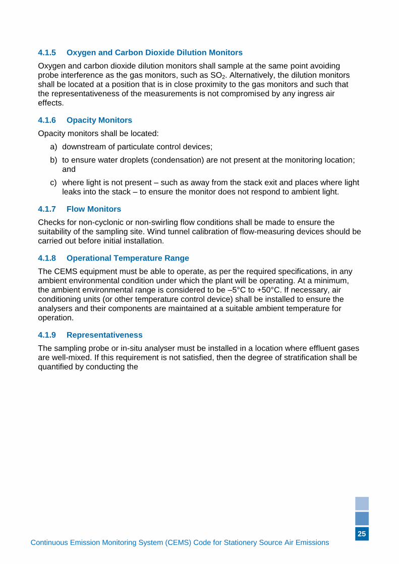
4.1.5 Oxygen and Carbon Dioxide Dilution Monitors .................................................. 25
4.1.6 Opacity Monitors ............................................................................................... 25
4.1.7 Flow Monitors ................................................................................................... 25
4.1.8 Operational Temperature Range....................................................................... 25
4.1.9 Representativeness .......................................................................................... 25
4.1.10 Other Monitors .................................................................................................. 26
4.2 Test procedures for Verifying Installation Specifications .......................................... 26
4.2.1 Stratification Test Procedure ............................................................................. 27
5. Phase III – Performance Testing ........................................................................ 28
5.1 Performance Specifications ..................................................................................... 28
5.1.1 Performance Specifications for Sulfur Dioxide, Oxides of Nitrogen, and Carbon Monoxide Monitoring Systems ........................................................................................ 28
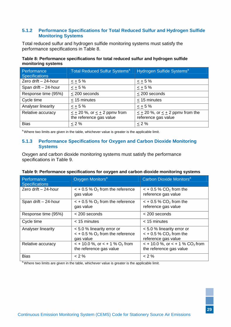
5.1.2 Performance Specifications for Total Reduced Sulfur and Hydrogen Sulfide Monitoring Systems ........................................................................................................ 29
5.1.3 Performance Specifications for Oxygen and Carbon Dioxide Monitoring Systems ......................................................................................................................... 29
5.1.4 Performance Specifications for in-stack Opacity Monitoring Systems ............... 30
5.1.5 Performance Specifications for Volumetric Flow/Velocity Monitoring Systems .. 30
5.1.6 Performance Specifications for Temperature Monitors (Sensors) ..................... 30
5.1.7 Other Monitors .................................................................................................. 30
5.2 Performance Testing Process .................................................................................. 30
5.2.1 Conditioning Process ........................................................................................ 30
5.2.2 Operational Testing Process ............................................................................. 31
5.3 Test Procedures for Verifying Performance Specifications ....................................... 32
5.3.1 Zero and Span Drift – 24-hour Tests for Gas and Dilution Monitoring Systems . 32
5.3.2 Zero and Span 24-hour Drift Test for Opacity Monitors ..................................... 33
5.3.3 Zero and Span Calibration Drift 24-hour For Volumetric Flow/Velocity Monitors 35
5.3.4 Flow Monitor Orientation Sensitivity .................................................................. 35
5.3.5 Response Time ................................................................................................. 35
5.3.6 Cycle Time ........................................................................................................ 35
5.3.7 Analyser Linearity ............................................................................................. 36
5.3.8 Relative Accuracy Test Audit (RATA) and Bias Tests ....................................... 37
5.3.9 Relative Accuracy Test for Flow Monitors ......................................................... 43
iv
Continuous Emission Monitoring System (CEMS) Code for Stationery Source Air Emissions (Version if applicable)
5.3.10 Relative Accuracy Test for Temperature Monitors (Sensors) ............................ 43
6. Phase IV – Ongoing Compliance Requirements .............................................. 43
6.1 Ongoing CEMS Compliance Requirements ............................................................. 43
6.1.1 Ongoing Compliance Specifications and Frequency ......................................... 43
6.2 Out-of-control Conditions ......................................................................................... 46
6.2.1 Calibration Adjustment ...................................................................................... 47
6.3 Test Procedures for Ongoing Compliance ............................................................... 47
6.3.1 General Requirements (Applicability) ................................................................ 47
6.3.2 Temperature Measurement Verification ............................................................ 47
6.3.3 Pressure Measurement Verification .................................................................. 47
6.3.4 Flow Element Verification.................................................................................. 47
6.3.5 Data Acquisition System Verification ................................................................. 48
6.3.6 Relative Accuracy Test Audit Procedures ......................................................... 48
6.3.7 Cylinder Gas Audits .......................................................................................... 48
6.3.8 Availability ......................................................................................................... 49
6.3.9 Annual Evaluation ............................................................................................. 49
7. Phase V – Reporting ........................................................................................... 50
7.1 General .................................................................................................................... 50
7.2 CEMS Data Retention Requirements ....................................................................... 50
7.3 Quality Assurance Reporting Requirements............................................................. 50
7.3.1 General Reporting ............................................................................................ 50
7.3.2 Relative Accuracy Test Audit (RATA) Reporting ............................................... 51
7.3.3 Annual Evaluation ............................................................................................. 51
Appendix A: Quality Assurance Requirements ...................................................... 52
1 General Requirements ........................................................................................ 52
2 Development, Approval and Issue of Documents ............................................ 52
3 Document Changes ............................................................................................ 53
4 Control of Records ............................................................................................. 53
5 Recording of Information and Data ................................................................... 53
6 Equipment ........................................................................................................... 54
7 Preventive Maintenance and Calibration .......................................................... 54
8 Corrective Action ................................................................................................ 54
9 Training of Personnel ......................................................................................... 55
10 Service, Suppliers and Contractors .................................................................. 55
11 Audits ................................................................................................................... 55
Appendix B: Methods Acceptable for Relative Accuracy Test Audits (RATAs) .. 56
Appendix C: References for this Document ........................................................... 58
1
Continuous Emission Monitoring System (CEMS) Code for Stationery Source Air Emissions (Version if applicable)
Definitions
The following definitions apply to this document:
accuracy The degree of agreement of the measurement made by a CEMS, a pollutant concentration monitor, thermocouple or a flow monitor, to the true value of the emission, temperature or volumetric flow. It is expressed as the difference between the measurement and a Reference Method value, which is assumed to be equivalent to the true value. Variation among these differences represents the variation in accuracy that could be caused by random or systematic error.
accreditation Current and formal recognition by a recognised accreditation authority that a laboratory is competent to carry out the relevant specific tests or calibrations or relevant types of tests or calibrations.
alternative monitoring system
A system designed to provide direct or indirect determinations of mass per unit time emissions, pollutant concentrations, and/or volumetric flow data that does not use analysers that accept independent, certified reference calibration gases. For the purposes of this CEMS Code, acceptable alternative monitoring systems are those that meet the same criteria of performance with respect to accuracy, precision, and availability, as CEMS that accept reference calibration gases.
angle of view The total angle that contains all of the visible (photopic) radiation detected by the photodetector assembly of the transmissometer (opacity monitor) at a level greater than 2.5 per cent of the peak detector response.
angle of projection The total angle that contains all of the visible (photopic) radiation projected from the light source of the transmissometer (opacity monitor) at a level greater than 2.5 per cent of its peak illuminance.
arithmetic mean A value that is computed by dividing the sum of a set of terms by the number of terms (also commonly referred to as average).
as found or unadjusted value
The output value of the measurement device corresponding to the reference value input before a calibration check or adjustment.
as left or adjusted value
The output value of the measurement device corresponding to the reference value input after calibration adjustment.
available The condition in which the CEMS or continuous in-stack opacity monitoring system is functional and operating within the calibration drift limits and other applicable performance specifications.
bias Systematic error; the result of bias is that measurements will be either consistently low or high, relative to the true value.
2
Continuous Emission Monitoring System (CEMS) Code for Stationery Source Air Emissions (Version if applicable)
bypass Any flue, duct, stack, or conduit through which emissions from a unit may or do pass to the atmosphere, which either augments or substitutes for the principal ductwork and stack exhaust system during any portion of the unit's operation.
calibration Comparison of a measurement standard or instrument with another standard or instrument to detect, correlate, report, or eliminate by adjustment any inaccuracy of the compared measurements or values.
calibration adjustment
The procedure to adjust the output of a device to bring it to a desired value (within a specified tolerance) for a particular value of input (typically the value of the reference standard).
calibration check The procedure of testing a device against a known reference standard without adjusting its output.
calibration drift The difference between either:
(1) the response of a gas monitor to a reference calibration gas and the known concentration of the gas;
(2) the response of a flow monitor to a reference signal and the known value of the reference signal; or
(3) the response of a continuous in-stack opacity monitoring system to an attenuation filter and the known value of the filter, after a stated period of operation during which no unscheduled maintenance, repair, or adjustment took place.
calibration gas For the purposes of this CEMS Code, means a gas certified by a laboratory with NATA accreditation for the production of the gas in question, to be within two per cent of the concentration specified on the cylinder label (tag value). The gas does not have to be traceable to a reference standard.
calibration gas cell or a filter
A device that, when inserted between the transmitter and detector of the analyser, produces a desired output level on the data recorder.
centroidal area A concentric area that is geometrically similar to the flue, duct or stack cross-section and is not greater than one per cent of the stack or duct cross-sectional area (i.e. the centre of the stack).
continuous For the purposes of this CEMS Code, means measurements taken every minute for dedicated systems, or at least once every 15 minutes for time-shared systems, and operates with an availability greater than 90 per cent on a monthly basis. For time-shared systems, the total of all measurement data from all analysers or monitors must equal 60 minutes for each hour.
continuous emission monitoring system (CEMS)
The instruments and equipment required to analyse, measure, and provide on a continuous basis, a permanent record of emission and other parameters as established by this CEMS Code.
3
Continuous Emission Monitoring System (CEMS) Code for Stationery Source Air Emissions (Version if applicable)
corrective action An action taken to eliminate the causes of an existing deficiency or other undesirable situation in order to prevent recurrence.
cycle time The time it takes to complete a measurement or cycle of measurements from all analysers in a time-shared system.
cylinder gas audit (CGA)
A challenge of the monitoring system with a cylinder gas of a known concentration that is traceable to standard reference materials produced by a laboratory with NATA accreditation for the reference material.
data acquisition system (DAS)
One or more devices used to receive, compute, store, and report CEMS measurement data from single or multiple measurement devices.
data recorder A device capable of providing a permanent record of both raw and summary data.
data point A discrete measurement made and recorded by the CEMS. For dedicated systems a data point equalling one-minute of data, with that minute consisting of an average of a minimum of six equally spaced measurements, is preferred. For time-shared systems, it is expected that a data point will consist of no less than the average of all measurements taken for a single analyser during each cycle time. At least 90 per cent of the measurements taken during the cycle must be valid for the data point to be considered valid.
(For example, for a five minute cycle a single data point averaging five minutes of minute-by-minute data is acceptable for long-term storage, but it is preferred that each minute of data is actually recorded for the short-term as five data points because it allows flexibility when performing comparisons with Relative Accuracy Test Audits. For more information see Section 3.2.1.)
dedicated system A CEMS that monitors a single pollutant or parameter.
diluent gas A major gaseous constituent in a gaseous pollutant mixture or the gas used to dilute the pollutant mixture in dilution type analyser systems. For combustion sources, carbon dioxide, nitrogen and oxygen are the major diluent gases.
dilution monitor For the purposes of this document, a monitor that measures oxygen or carbon dioxide.
downstream In the direction of the stack gas flow (for example a point near the top/exit of the stack would be downstream of a point near where the gases enter the stack).
drift An undesired change in output, over a period of time, that is unrelated to input or equipment adjustments.
dual span system A pollutant concentration monitor, flow monitor, or in-stack opacity monitor that has two ranges of values over which measurements are made.
4
Continuous Emission Monitoring System (CEMS) Code for Stationery Source Air Emissions (Version if applicable)
equivalent diameter A calculated value used to determine the upstream and downstream distances for locating flow or pollutant concentration monitors in flues, ducts or stacks with rectangular cross-sections.
extractive monitoring system
A system that withdraws a gas sample from the stack and transports the sample to the analyser.
flow monitor An analyser that measures the velocity and volumetric flow of an effluent stream.
full scale reading The upper value of the monitor or analyser range.
gas monitor For the purposes of this document, a monitor that measures sulfur dioxide, oxides of nitrogen, carbon monoxide, total reduced sulfur or hydrogen sulfide.
in-situ monitor A monitor that senses the gas concentration in the flue, duct or stack effluent stream and does not extract a sample for analysis.
inspection A check for conditions that are likely to affect the reliability of the system. Examples of these conditions could include the following:
damage to system components;
leaks;
a low flow condition in sample transport system;
alarms;
adequate supply of consumables such as chart paper; and
reference/calibration gases.
interference rejection
The ability of a CEMS to measure a gaseous species without responding to other gases or substances, within specified limits.
internal diameter The inside diameter of a circular stack, or the equivalent diameter of a rectangular duct (four times the duct area, divided by the duct perimeter).
invalid data Data that were generated while the measurement device(s) was out-of-control.
licence A licence granted and in force under Part V of the Environmental Protection Act 1986.
licence emission limit
The maximum emission level (for example a concentration or mass) as stated in a licence issued under the Environmental Protection Act 1986.
linearity The degree to which a CEMS exhibits a straight line (first order) response to changes in concentration (or other monitored value), over the range of the system. Non-linearity is expressed as the percentage difference of the response from a straight line response.
lower detection limit
The minimum value that a device can measure, which may be a function of the design and materials of construction of the device rather than of its configuration.
month A calendar month.
5
Continuous Emission Monitoring System (CEMS) Code for Stationery Source Air Emissions (Version if applicable)
NIST/EPA approved reference material
A reference material for which one or more of its values are certified by a technically valid procedure and accompanied by or traceable to a certificate or other documentation that is issued by a certifying body and approved by the United States Environmental Protection Agency (USEPA).
normal production A normal, substantive production rate or throughput for the facility, or process unit, avoiding start-up, shut-down, abnormal or upset conditions; or as stipulated in a works approval or licence condition.
operational period A minimum period of time over which a measurement system is expected to operate within certain performance specifications, as set forth in this CEMS Code, without unscheduled maintenance, repair, or adjustment.
orientation sensitivity
The degree to which a flow monitoring system is affected by its change in orientation to give an accurate flow measurement.
out-of-control The state in which an analyser or CEMS is not generating acceptable quality assured data.
path continuous emission monitoring system
A CEMS that measures the analyte concentration along a path greater than 10 per cent of the equivalent diameter of the stack or duct cross-section.
permanent Continuing or enduring without fundamental or marked change (for example indelible ink is considered permanent, while pencil is not).
point continuous emission monitoring system
A CEMS that measures the analyte concentration along a path less than or equal to 10 per cent of the equivalent diameter of the stack or duct cross-section.
precision The closeness of a measurement to the actual measured value expressed as the uncertainty associated with repeated measurements of the same sample or of different samples from the same process (for example the random error associated with simultaneous measurements of a process made by more than one instrument). A measurement technique is determined to have increasing precision as the variation among the repeated measurements decreases.
protocol 1 gas A calibration gas mixture prepared and analysed according to Revised Traceability Protocol No.1 US Code of Federal Regulations, 40CFR75, Appendix H to Part 75. The certified concentrations for calibration gas mixtures developed using the protocol are traceable to a standard reference material or a National Institute of Standards and Technology (NIST)/EPA approved certified reference material.
quality assurance (QA)
An integrated system of management activities involving planning, implementation, assessment, reporting, and quality improvement to ensure that a process, item, or service is of the type and quality needed and expected by the end user.
6
Continuous Emission Monitoring System (CEMS) Code for Stationery Source Air Emissions (Version if applicable)
quality assured data
Data and information generated and/or collected in accordance with the requirements of the Quality Assurance Plan.
quality assurance plan
A formal document describing in comprehensive detail the necessary quality assurance procedures, quality control activities, and other technical activities that need to be implemented to ensure that the results of the work performed will satisfy the stated performance or acceptance criteria.
quality control (QC) The overall system of technical activities that measures the attributes and performance of a process, item, or service against defined standards to verify that they meet the specifications established by the customer; operational techniques and activities that are used to fulfill the need for quality.
range The algebraic difference between the upper and lower limits of the group of values within which a quantity is measured, received or transmitted.
raw data Any original factual information from a measurement activity or study recorded in laboratory worksheets, records, memoranda, notes, or exact copies thereof and that are necessary for the reconstruction and evaluation of the report of the activity or study. Raw data may include photographs, microfilm or microfiche copies, computer printouts, magnetic media, including dictated observations, and recorded data from automated instruments. If exact copies of raw data have been prepared (for example tapes which have been transcribed verbatim, dated, and verified accurate by signature), the exact copy or exact transcript may be substituted.
record A completed document that provides objective evidence of an item or process. Records may include photographs, drawings, magnetic tape, and other data recording media.
reference calibration gas
For the purposes of this CEMS Code, means a known concentration of gas that is traceable to a reference material that is either:
1) a standardised reference material (SRM) distributed and certified by the USA National Institute of Standards and Technology (NIST) or the Canadian Standards Association (CSA);
2) a protocol 1 gas; or
3) an equivalent gas certified by a laboratory with NATA accreditation for the production of the gas in question, to be within 2.0 per cent of the concentration specified on the cylinder label (tag value), and is traceable to the standard reference material.
reference method Any method of sampling and analysing for a substance, or determining the velocity or volumetric flow rate, as specified in Appendix B of this document.
7
Continuous Emission Monitoring System (CEMS) Code for Stationery Source Air Emissions (Version if applicable)
reference value (RV)
The known concentration of a verification or reference calibration gas or the known value of a reference thermometer or output value of a temperature, pressure, current or voltage calibrator.
relative accuracy The absolute mean difference between the gas concentration or emission rate determined by a CEMS and the value determined by an appropriate Reference Method plus the 2.5 per cent error confidence coefficient of a series of tests, divided by the mean of the Reference Method tests. The relative accuracy provides a measure of the systematic and random errors associated with data from a CEMS.
representative A sample whose characteristics reflect those of the population from which it is drawn.
response time The amount of time required for the CEMS to display on the data recorder 95 per cent of a step change in pollutant concentration. This period includes the time from when the sample is first extracted from the flue, duct or stack (if using an extractive system) to when the concentration is recorded.
sampling location The cross-sectional plane within a stack or duct at which the CEMS or Reference Method sampling occurs.
sampling point The individual positions in the sampling plane at which CEMS or Reference Method samples are drawn.
span The highest value of a parameter, in whatever unit, that a monitor is required to measure.
span drift The difference between the CEMS response to a high-range calibration value and the reference value after a stated period of operation during which no unscheduled maintenance, repair, or adjustment took place.
standard absolute pressure
A pressure of 101.325 kPa (760 mm Hg, 1 atmosphere).
standard absolute temperature
A temperature of 0°C (273K, 32°F, 460°R).
standard reference material
A reference material distributed and certified by a laboratory with NATA accreditation for the production of the reference material.
summary data Data that has been derived through the calculation, alteration, manipulation or summarisation of raw data.
temperature-responsive zero drift
The zero drift of an analyser for any 10°C change in temperature over the ambient temperature range of 5°C to 35°C.
temperature-responsive span drift
The span drift of an analyser for any 10°C change in temperature over the ambient temperature range of 5°C to 35°C.
8
Continuous Emission Monitoring System (CEMS) Code for Stationery Source Air Emissions (Version if applicable)
time-shared system A CEMS that monitors more than one pollutant or parameter through the shared use of the data acquisition system.
traceability The property of the result of a measurement or the value of a standard whereby it can be related to stated references, usually national or international standards, through an unbroken chain of comparisons all having stated uncertainties.
traverse A line, passing through the centroidal area of a stack or duct, along which the sampling points (also known as traverse points) are located.
uncertainty The estimated amount by which an observed or calculated value may depart from the true value.
upstream In the direction opposite of the stack gas flow (for example a point near where the gases enter the stack would be upstream of a point near the top/exit of the stack).
valid hour The data for a given hour consisting of 60 minutes of data for dedicated systems, or at least four or more equally spaced data points, totalling 60 minutes worth of data for time-shared systems (in accordance with the requirements for cycle time, Section 3.3.12). During the periods that calibrations, quality assurance activities, maintenance, or repairs are being carried out, a valid hour shall consist of a minimum of two (2) data points for a time-shared system, or 30 minutes of data for a CEM system using dedicated analysers. The hour shall start at one second after the clock hour.
valid in-stack opacity period
The data for a given time period consisting of at least 36 equally spaced data points. For example, for a six-minute time period, a minimum of 36 samples (cycles) shall be obtained, based on a standard rate of sampling at no less than six samples (cycles) per minute. The data collected in the 36 cycles may be reduced to a single averaged value.
verification The process of evaluating the completeness, correctness, and conformance/compliance of a specific data set against the method, procedure, or specifications.
zero drift The difference between the CEMS response to a low-range calibration value and the reference value after a stated period of operation during which no unscheduled maintenance, repair, or adjustment took place.
9
Continuous Emission Monitoring System (CEMS) Code for Stationery Source Air Emissions (Version if applicable)
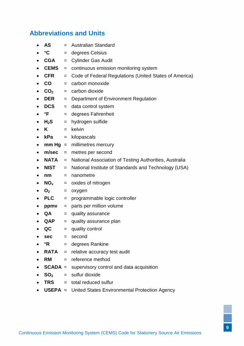
Abbreviations and Units
AS = Australian Standard
°C = degrees Celsius
CGA = Cylinder Gas Audit
CEMS = continuous emission monitoring system
CFR = Code of Federal Regulations (United States of America)
CO = carbon monoxide
CO2 = carbon dioxide
DER = Department of Environment Regulation
DCS = data control system
°F = degrees Fahrenheit
H2S = hydrogen sulfide
K = kelvin
kPa = kilopascals
mm Hg = millimetres mercury
m/sec = metres per second
NATA = National Association of Testing Authorities, Australia
NIST = National Institute of Standards and Technology (USA)
nm = nanometre
NOx = oxides of nitrogen
O2 = oxygen
PLC = programmable logic controller
ppmv = parts per million volume
QA = quality assurance
QAP = quality assurance plan
QC = quality control
sec = second
°R = degrees Rankine
RATA = relative accuracy test audit
RM = reference method
SCADA = supervisory control and data acquisition
SO2 = sulfur dioxide
TRS = total reduced sulfur
USEPA = United States Environmental Protection Agency
10
Continuous Emission Monitoring System (CEMS) Code for Stationery Source Air Emissions (Version if applicable)
1. Introduction
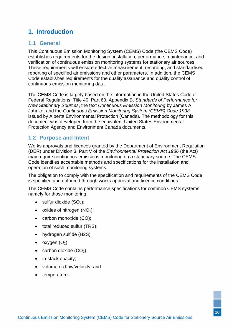
1.1 General
This Continuous Emission Monitoring System (CEMS) Code (the CEMS Code) establishes requirements for the design, installation, performance, maintenance, and verification of continuous emission monitoring systems for stationary air sources. These requirements will ensure effective measurement, recording, and standardised reporting of specified air emissions and other parameters. In addition, the CEMS Code establishes requirements for the quality assurance and quality control of continuous emission monitoring data. The CEMS Code is largely based on the information in the United States Code of Federal Regulations, Title 40, Part 60, Appendix B, Standards of Performance for New Stationary Sources, the text Continuous Emission Monitoring by James A. Jahnke, and the Continuous Emission Monitoring System (CEMS) Code 1998, issued by Alberta Environmental Protection (Canada). The methodology for this document was developed from the equivalent United States Environmental Protection Agency and Environment Canada documents.
1.2 Purpose and Intent
Works approvals and licences granted by the Department of Environment Regulation (DER) under Division 3, Part V of the Environmental Protection Act 1986 (the Act) may require continuous emissions monitoring on a stationary source. The CEMS Code identifies acceptable methods and specifications for the installation and operation of such monitoring systems.
The obligation to comply with the specification and requirements of the CEMS Code is specified and enforced through works approval and licence conditions.
The CEMS Code contains performance specifications for common CEMS systems, namely for those monitoring:
sulfur dioxide (SO2);
oxides of nitrogen (NOx);
carbon monoxide (CO);
total reduced sulfur (TRS);
hydrogen sulfide (H2S);
oxygen (O2);
carbon dioxide (CO2);
in-stack opacity;
volumetric flow/velocity; and
temperature.
11
Continuous Emission Monitoring System (CEMS) Code for Stationery Source Air Emissions (Version if applicable)
1.3 Use of this CEMS Code
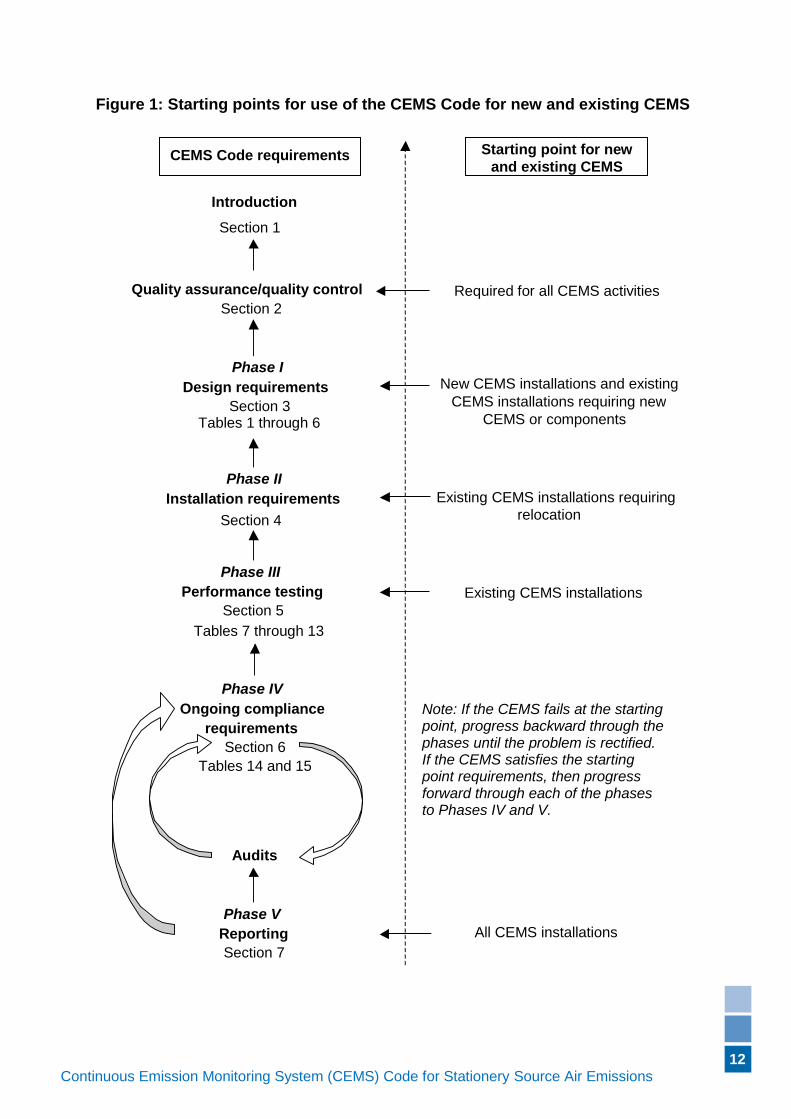
New CEMS installations must meet all applicable requirements of this CEMS Code. Existing CEMS installations are to conduct the Operational Testing Process in order to determine compliance with the applicable Performance Specifications. If compliance can be demonstrated, then the Design and Installation Requirements are waived. If compliance cannot be demonstrated, then appropriate action must be taken to achieve compliance. If a new CEMS, or new CEMS components (except for the data acquisition system), are required for compliance then they are to be treated as a new installation and all CEMS Code requirements must be satisfied, as applicable for that type of monitor. If compliance can be achieved through relocation of an existing CEMS, or CEMS component, then all requirements for that type of monitor, except for the Design Requirements, are applicable. The Operational Testing Process must be repeated for the relocated CEMS, or CEMS components, and compliance with the applicable Performance Specifications must be demonstrated (see Figure 1). The licensee shall conduct Relative Accuracy Test Audits (RATAs) and Cylinder Gas Audits (CGAs) on each CEMS (see Section 6). For the first year of CEMS operation after the implementation of the CEMS Code, a minimum of two Relative Accuracy Test Audits and a minimum of two CGAs must be conducted on each CEMS. A RATA may be substituted in place of a CGA; however, a CGA cannot be substituted in place of a RATA. For the second and succeeding years, the minimum frequency of RATAs may be decreased to once per year upon DER being satisfied that the quality assurance plan (QAP) demonstrates compliance with ongoing CEMS requirements (as detailed in Section 6.1). In lieu of the decreased RATA frequency, the minimum CGA frequency would be increased to three times per year. This decreased RATA frequency will need to be specified in a licence.
12
Continuous Emission Monitoring System (CEMS) Code for Stationery Source Air Emissions (Version if applicable)
New CEMS installations and existing
CEMS installations requiring new
CEMS or components
Existing CEMS installations requiring
relocation
Existing CEMS installations
Starting point for new
and existing CEMS
Required for all CEMS activities
All CEMS installations
CEMS Code requirements
Introduction
Section 1
Quality assurance/quality control
Section 2
Phase I
Design requirements
Section 3 Tables 1 through 6
Phase III
Performance testing
Section 5
Tables 7 through 13
Phase IV
Ongoing compliance
requirements
Section 6
Tables 14 and 15
Phase II
Installation requirements
Section 4
Audits
Phase V
Reporting
Section 7
Note: If the CEMS fails at the starting point, progress backward through the phases until the problem is rectified. If the CEMS satisfies the starting point requirements, then progress forward through each of the phases to Phases IV and V.
Figure 1: Starting points for use of the CEMS Code for new and existing CEMS
58
Continuous Emission Monitoring System (CEMS) Code for Stationery Source Air Emissions (Version if applicable)
2. Quality Assurance / Quality Control
2.1 Quality Assurance Plan (QAP)
A QAP must be written, implemented, maintained and followed. It must include and describe a complete program of activities to be implemented that will ensure that the data generated by the CEMS is complete, accurate, precise, traceable and reliable.
The QAP must satisfy the requirements listed in
14
Continuous Emission Monitoring System (CEMS) Code for Stationery Source Air Emissions (Version if applicable)
Appendix A, and any other requirement which is necessary to ensure the accuracy, precision, traceability and reliability of the data and information.
When the quality assurance (QA) assessment activities indicate that the data quality is inadequate, the quality control (QC) efforts must be increased until the data quality is acceptable. If it is determined that data quality is inadequate, then appropriate corrective action shall be determined and implemented as soon as possible.
For example, if a QA audit identifies the data to not be complete, accurate, precise, traceable and reliable, then corrective action must be taken to ensure the quality control measures are adequate and appropriate to assure that the data is complete, accurate, precise, traceable and reliable.
2.2 National Association of Testing Authorities (NATA) Accreditation
This document includes requirements for method accreditation by the NATA. DER recognises that other acceptable accreditation associations do exist and references to NATA are not intended to limit equivalent accreditation.
For the purposes of this document, references to NATA accreditation are to be interpreted as:
a) current NATA accreditation for the methods and/or analyses specified, or
b) current accreditation for internationally, nationally or state-accepted standards comparable to those required by NATA for the methods and/or analyses specified, including a competency assessment against the international standard ISO/IEC 17025.
It is the responsibility of the licence holder to ensure the accreditation meets the above criteria.
2.3 Accuracy of Verification/Calibration Equipment and Materials
Timing devices used for the verification/calibration equipment and materials used in the conduct of a Response Time test procedure must be accurate to at least 0.5 seconds.
Timing devices used for the verification/calibration equipment and materials used in the conduct of a Cycle Time test procedure must be accurate to at least one second.
For analysers, the use of calibration gases is acceptable for the daily Zero and Span Drift performance verifications. Reference calibration gases are required for a CGA.
Calibration equipment such as test pressure gauges, dead weight testers and multi-meters must be calibrated at least every two years by an NATA accredited laboratory using NATA accredited methods for the required calibrations.
15
Continuous Emission Monitoring System (CEMS) Code for Stationery Source Air Emissions (Version if applicable)
Equipment used in the conduct of stationary source air monitoring equipment used in the conduct of a RATA must be calibrated as per the NATA accreditation requirements, or the accreditation requirements of another accreditation body as defined in Section 2.2 b), for that testing facility.
For parameters for which cylinder gases are unstable, or are unavailable, alternative calibration techniques will need to be specified in a licence and documented in the QAP.
3. Phase I – Design Requirements
3.1 Design Specifications for Monitors and Analysers
3.1.1 Design Specifications for Sulfur Dioxide, Oxides of Nitrogen and Carbon Monoxide Analysers
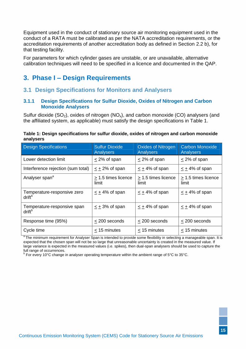
Sulfur dioxide (SO2), oxides of nitrogen (NOx), and carbon monoxide (CO) analysers (and the affiliated system, as applicable) must satisfy the design specifications in Table 1.
Table 1: Design specifications for sulfur dioxide, oxides of nitrogen and carbon monoxide analysers
Design Specifications Sulfur Dioxide Analysers
Oxides of Nitrogen Analysers
Carbon Monoxide Analysers
Lower detection limit < 2% of span < 2% of span < 2% of span
Interference rejection (sum total) < + 2% of span < + 4% of span < + 4% of span
Analyser spana > 1.5 times licence limit
> 1.5 times licence limit
> 1.5 times licence limit
Temperature-responsive zero driftb
< + 4% of span < + 4% of span < + 4% of span
Temperature-responsive span driftb
< + 3% of span < + 4% of span < + 4% of span
Response time (95%) < 200 seconds < 200 seconds < 200 seconds
Cycle time < 15 minutes < 15 minutes < 15 minutes a
The minimum requirement for Analyser Span is intended to provide some flexibility in selecting a manageable span. It is expected that the chosen span will not be so large that unreasonable uncertainty is created in the measured value. If large variance is expected in the measured values (i.e. spikes), then dual-span analysers should be used to capture the full range of occurrences. b For every 10°C change in analyser operating temperature within the ambient range of 5°C to 35°C.
16
Continuous Emission Monitoring System (CEMS) Code for Stationery Source Air Emissions (Version if applicable)
3.1.2 Design Specifications for Total Reduced Sulfur (TRS) and Hydrogen Sulfide Analysers
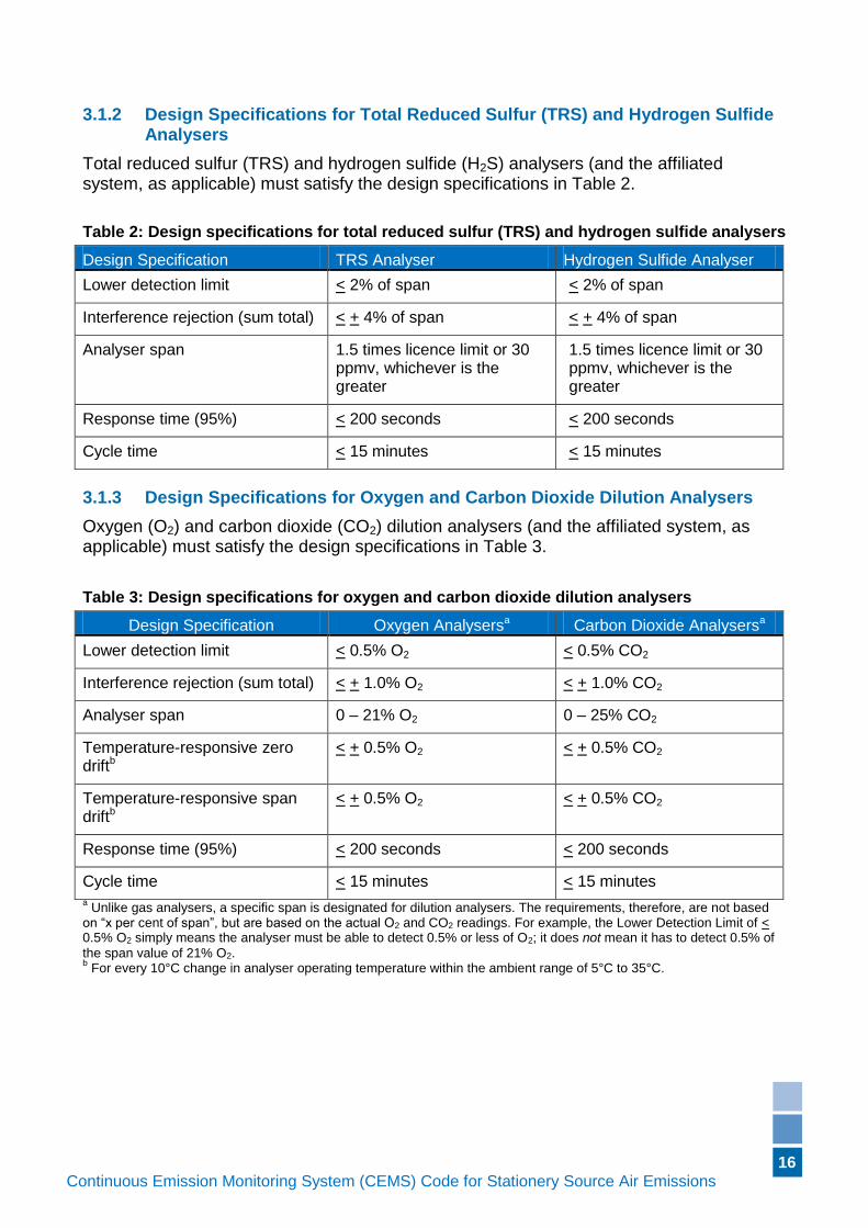
Total reduced sulfur (TRS) and hydrogen sulfide (H2S) analysers (and the affiliated system, as applicable) must satisfy the design specifications in Table 2.
Table 2: Design specifications for total reduced sulfur (TRS) and hydrogen sulfide analysers
Design Specification TRS Analyser Hydrogen Sulfide Analyser
Lower detection limit < 2% of span < 2% of span
Interference rejection (sum total) < + 4% of span < + 4% of span
Analyser span 1.5 times licence limit or 30 ppmv, whichever is the greater
1.5 times licence limit or 30 ppmv, whichever is the greater
Response time (95%) < 200 seconds < 200 seconds
Cycle time < 15 minutes < 15 minutes
3.1.3 Design Specifications for Oxygen and Carbon Dioxide Dilution Analysers
Oxygen (O2) and carbon dioxide (CO2) dilution analysers (and the affiliated system, as applicable) must satisfy the design specifications in Table 3.
Table 3: Design specifications for oxygen and carbon dioxide dilution analysers
Design Specification Oxygen Analysersa Carbon Dioxide Analysersa
Lower detection limit < 0.5% O2 < 0.5% CO2
Interference rejection (sum total) < + 1.0% O2 < + 1.0% CO2
Analyser span 0 – 21% O2 0 – 25% CO2
Temperature-responsive zero driftb
< + 0.5% O2 < + 0.5% CO2
Temperature-responsive span driftb
< + 0.5% O2 < + 0.5% CO2
Response time (95%) < 200 seconds < 200 seconds
Cycle time < 15 minutes < 15 minutes a Unlike gas analysers, a specific span is designated for dilution analysers. The requirements, therefore, are not based
on “x per cent of span”, but are based on the actual O2 and CO2 readings. For example, the Lower Detection Limit of < 0.5% O2 simply means the analyser must be able to detect 0.5% or less of O2; it does not mean it has to detect 0.5% of
the span value of 21% O2. b For every 10°C change in analyser operating temperature within the ambient range of 5°C to 35°C.
17
Continuous Emission Monitoring System (CEMS) Code for Stationery Source Air Emissions (Version if applicable)
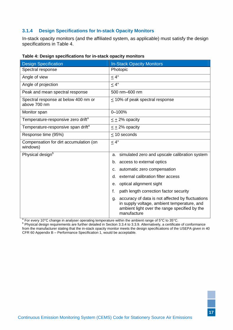
3.1.4 Design Specifications for In-stack Opacity Monitors
In-stack opacity monitors (and the affiliated system, as applicable) must satisfy the design specifications in Table 4.
Table 4: Design specifications for in-stack opacity monitors
Design Specification In-Stack Opacity Monitors
Spectral response Photopic
Angle of view < 4°
Angle of projection < 4°
Peak and mean spectral response 500 nm–600 nm
Spectral response at below 400 nm or above 700 nm
< 10% of peak spectral response
Monitor span 0–100%
Temperature-responsive zero drifta < + 2% opacity
Temperature-responsive span drifta < + 2% opacity
Response time (95%) < 10 seconds
Compensation for dirt accumulation (on windows)
< 4°
Physical designb a. simulated zero and upscale calibration system
b. access to external optics
c. automatic zero compensation
d. external calibration filter access
e. optical alignment sight
f. path length correction factor security
g. accuracy of data is not affected by fluctuations in supply voltage, ambient temperature, and ambient light over the range specified by the manufacture
a For every 10°C change in analyser operating temperature within the ambient range of 5°C to 35°C.
b Physical design requirements are further detailed in Section 3.3.4 to 3.3.9. Alternatively, a certificate of conformance
from the manufacturer stating that the in-stack opacity monitor meets the design specifications of the USEPA given in 40 CFR 60 Appendix B – Performance Specification 1, would be acceptable.
18
Continuous Emission Monitoring System (CEMS) Code for Stationery Source Air Emissions (Version if applicable)
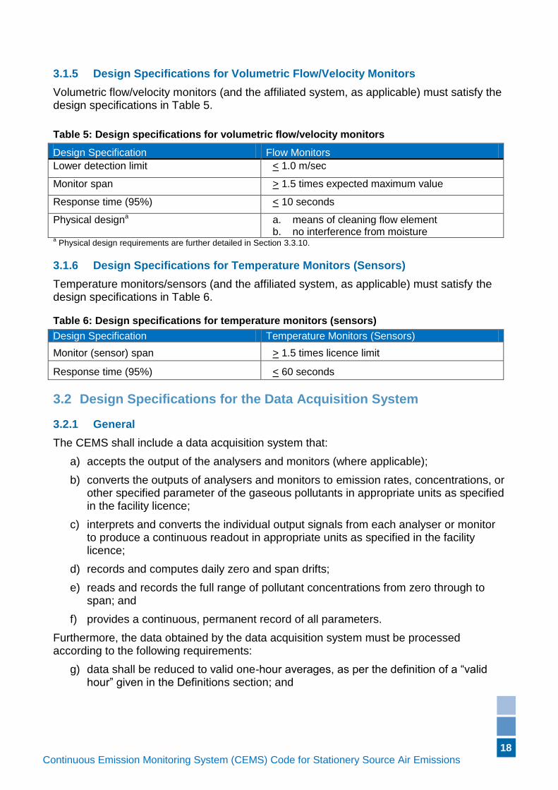
3.1.5 Design Specifications for Volumetric Flow/Velocity Monitors
Volumetric flow/velocity monitors (and the affiliated system, as applicable) must satisfy the design specifications in Table 5.
Table 5: Design specifications for volumetric flow/velocity monitors
Design Specification Flow Monitors
Lower detection limit < 1.0 m/sec
Monitor span > 1.5 times expected maximum value
Response time (95%) < 10 seconds
Physical designa a. means of cleaning flow element b. no interference from moisture
a Physical design requirements are further detailed in Section 3.3.10.
3.1.6 Design Specifications for Temperature Monitors (Sensors)
Temperature monitors/sensors (and the affiliated system, as applicable) must satisfy the design specifications in Table 6.
Table 6: Design specifications for temperature monitors (sensors)
Design Specification Temperature Monitors (Sensors)
Monitor (sensor) span > 1.5 times licence limit
Response time (95%) < 60 seconds
3.2 Design Specifications for the Data Acquisition System
3.2.1 General
The CEMS shall include a data acquisition system that:
a) accepts the output of the analysers and monitors (where applicable);
b) converts the outputs of analysers and monitors to emission rates, concentrations, or other specified parameter of the gaseous pollutants in appropriate units as specified in the facility licence;
c) interprets and converts the individual output signals from each analyser or monitor to produce a continuous readout in appropriate units as specified in the facility licence;
d) records and computes daily zero and span drifts;
e) reads and records the full range of pollutant concentrations from zero through to span; and
f) provides a continuous, permanent record of all parameters.
Furthermore, the data obtained by the data acquisition system must be processed according to the following requirements:
g) data shall be reduced to valid one-hour averages, as per the definition of a “valid hour” given in the Definitions section; and
19
Continuous Emission Monitoring System (CEMS) Code for Stationery Source Air Emissions (Version if applicable)
h) during each 24-hour period, one one-hour average may consist of a minimum of two equally spaced data points for time-shared systems, or a total of 30 minutes of data for a dedicated system, to allow for calibration, quality assurance activities, maintenance, or repairs. If this minimum data accumulation is not achieved, the hour will be counted as missing data for the purposes of calculating availability.
The 24-hour period begins at one second past 2400 hours (midnight). The CEM system, in general, must also:
i) provide operators with visual or auditory alarms or fault condition warnings to facilitate proper operation and maintenance of the CEMS.
It should be noted that the CEMS operators should carefully consider the number of data points that will be recorded per hour. Also note that due to the large amount of data received by the data acquisition system, it is accepted that not every piece of data will be recorded, but may however be used in calculations to produce one recorded data point. For example, data collected every second is not expected to be kept for posterity, but may be averaged to give a one-minute average data point which would then be recorded and retained.
Due to the Performance Specification requirements of Section 0, the times of CEMS data collected will need to be accurately compared to the time of the Reference Method stack tests (a minimum of 21 minutes test time, or as per the Reference Method requirements). If possible, one-minute data averages are suggested as they allow for greater flexibility in ensuring accurate data comparison, however, it is noted that this will require greater data storage capacity. The number of data points collected per hour may be determined by the CEMS operator, provided the requirements as per the definitions listed in this document are satisfied, and the temporal correlation of CEMS data with the Reference Method tests can be accurately achieved.
3.2.2 Data Recorder Resolution
Data recorder hard copy resolution for system response shall be 0.5 per cent of full scale or better. Data recorder hard copy time resolution shall be no less than one minute. For example, every 30 seconds would be acceptable, but not every 90 seconds.
3.3 Test Procedures for Verifying Design Specifications
Relevant design specifications for the various analysers are detailed in Table 1 through Table 6, inclusive. The test procedures, and/or certificates of conformance, required for demonstrating compliance with the specifications are described below. Specifications, that are simply a requirement and do not have a specific test procedure, such as an analyser span, are not described here.
3.3.1 Lower Detection Limit
A manufacturer’s certificate of conformance, which demonstrates that the monitor is in compliance with the applicable specification, is deemed to be an acceptable alternative to testing.
20
Continuous Emission Monitoring System (CEMS) Code for Stationery Source Air Emissions (Version if applicable)
3.3.2 Interference Rejection
This test may be carried out after the analysers have been installed in the CEMS or in a laboratory or other suitable location before the analysers are installed. Sufficient time must be allowed for the analyser under test to warm up, and then the analyser must first be calibrated by introducing appropriate low-range and high-range gases directly to the analyser sample inlet. After the initial calibration, test gases shall be introduced, each containing a single interfering gas at a concentration representative of that species in the gas flow to be monitored. The magnitude of the interference of each potential interfering species on the target gas shall then be determined, and the sum total of all interferences must satisfy the applicable specification.
A manufacturer’s certificate of conformance, which demonstrates that the monitor was tested according to the procedures given above and is in compliance with the applicable specification, is deemed to be an acceptable alternative to testing.
3.3.3 Temperature-responsive Zero and Span Drift
Place the analyser in a temperature controlled climate chamber in which the chamber temperature can be varied from at least 5°C to 35°C. Allow sufficient time for the chamber to warm up, and ensure that the analyser temperature has stabilised before commencing. Calibrate the analyser at 25°C using appropriate zero and span gases. Do not turn off the power to the analyser over the duration of this test.
When the analyser has stabilised at the climate chamber temperature (each of 5, 15, 25 and 35°C), introduce the zero and span reference calibration gases at the same flow or pressure conditions, and note the response of the analyser.
Calculate the temperature-responsive zero drift from the difference in the indicated zero reading and the zero reading at the next higher or lower temperature, relative to full scale (span). The analyser is acceptable if the difference between all adjacent (such as 5/15°C, 15/25°C, and 25/35°C) zero responses meets the criteria in the applicable design specification table.
Calculate the temperature-responsive span drift from the differences between adjacent span responses, relative to the value of the reference calibration gas. An analyser is acceptable if the difference between all adjacent span responses meets the criteria in the applicable design specification table.
A manufacturer’s certificate of conformance, which demonstrates that the monitor was tested according to the procedures given above and is in compliance with the applicable specifications, is deemed to be an acceptable alternative to testing.
3.3.4 Simulated Zero and Upscale Calibration System
Each opacity analyser must include a calibration system for simulating both a zero and an upscale in-stack opacity value for the purpose of performing periodic checks of the monitor calibration while the monitor is on an operating stack or duct. This calibration system will provide, as a minimum, a system check of the analyser internal optics and all electronic circuitry including the lamp and photodetector assembly.
3.3.5 Access to External Optics
Each opacity analyser must provide a means of access to the optical surfaces exposed to the flue gas flow in order to permit the surfaces to be cleaned without requiring removal of the unit from the source mounting or without requiring optical realignment of the unit.
21
Continuous Emission Monitoring System (CEMS) Code for Stationery Source Air Emissions (Version if applicable)
3.3.6 Automatic Zero Compensation
If the opacity system has a feature that provides automatic zero compensation for dust accumulation on exposed optical surfaces, the system must also provide some means of indicating when a compensation of four per cent in-stack opacity has been exceeded (the exposed optical surfaces need cleaning if four per cent in-stack opacity is exceeded).
3.3.7 External Calibration Filter Access
The opacity monitor must accommodate the use of an external calibration filter, or a comparable device, which provides an independent assessment of the instrument performance when using independent audit filters.
3.3.8 Optical Alignment Sight
Each opacity analyser must provide some method for visually determining that the instrument is optically aligned. The method provided must be capable of indicating that the unit is misaligned when an error of greater than or equal to + two per cent occurs in the opacity readings at the calibrated path-length.
3.3.9 Path Length Correction Factor Security for Opacity Analysers
The value of the path length correction factor must be certified by the manufacturer and that either:
a) it cannot be changed by the end user; or
b) it is recorded during each calibration check cycle; or
c) the system must provide an alarm when the value is changed from the certified value.
3.3.10 Cleaning
If necessary, differential pressure volumetric flow/velocity monitors shall provide an automatic, timed period of back-purging or equivalent method of sufficient force and frequency to keep the sample port and probe and lines free of obstructions. Differential pressure flow monitors shall provide a method (either manual or automated) for detecting leaks or plugging throughout the system. Thermal flow monitors and ultrasonic monitors shall provide a method for detecting probe fouling and a means of cleaning the transducer surface in-situ or by removal and cleaning.
3.3.11 Response Time
The response time for gas analysers is the average time interval between injecting the gas at the probe (of the completely assembled and functioning system) and reaching a response of 95 per cent of the concentration value, as displayed on the data recorder. For opacity, instead of injecting gas, a high-level calibration attenuator (screen or other neutral density filter) is inserted in front of the beam and the response measured. For volumetric flow/velocity monitors and temperature monitors (sensors) use a reference signal in lieu of a reference calibration gas.
Perform a response time test for each CEMS according to the following procedures. Use a low-level (0 per cent to 20 per cent span) and a high-level (80 per cent to 100 per cent) reference calibration gas for this test.
Begin by injecting one of the reference calibration gases into the system at the probe.
22
Continuous Emission Monitoring System (CEMS) Code for Stationery Source Air Emissions (Version if applicable)
While the CEMS is measuring and recording the concentration, inject the other reference calibration gas into the same injection port and note the start time of injection. Continue injecting the gas until a stable response is reached. Using the data acquisition system output values, record the amount of time required for the monitor or monitoring system to complete 95.0% of the concentration step change. Repeat the procedure, but reverse the order of the gases injected (i.e. if the low-level gas was injected first, now inject it second to induce the step-change).
For CEMS that perform a series of operations (such as purge, sample, and analyse), time the injections of the reference calibration gases so they will produce the longest possible response time. Do not confuse this with cycle time (see Section 3.3.12), and do not include time periods that involve switching between various monitors on a cyclical basis. Note, for some CEMS, dilution is an integral part of the final calculated value, such as emission rates, and it will be necessary to simultaneously inject reference calibration gases into the gas and diluent monitors in order to measure the step change.
3.3.12 Cycle Time
In some instances, CEMS may be a part of a time-shared system, meaning that the data acquisition system alternates in capturing data from two or more monitors. The cycle time specification applies to the entire system, as opposed to single analysers. One complete measurement or cycle of measurements of all effluent streams must be completed in 15 minutes or less, and must perform all purging, sampling, analysis and other necessary functions during this time period. For example, if three SO2 analysers time-share a single data logger system, then the data must be retrieved from all three analysers within a 15-minute cycle.
23
Continuous Emission Monitoring System (CEMS) Code for Stationery Source Air Emissions (Version if applicable)
4. Phase II – Installation Requirements
4.1 Installation Specifications
4.1.1 Location of the Sampling Site
CEMS are to be sited in a location and in such an orientation such that:
a) the measurements obtained are representative of the actual emissions;
b) effluent gases are well-mixed; and
c) it is accessible at all times (in accordance with safety regulations) and during any normal weather conditions.
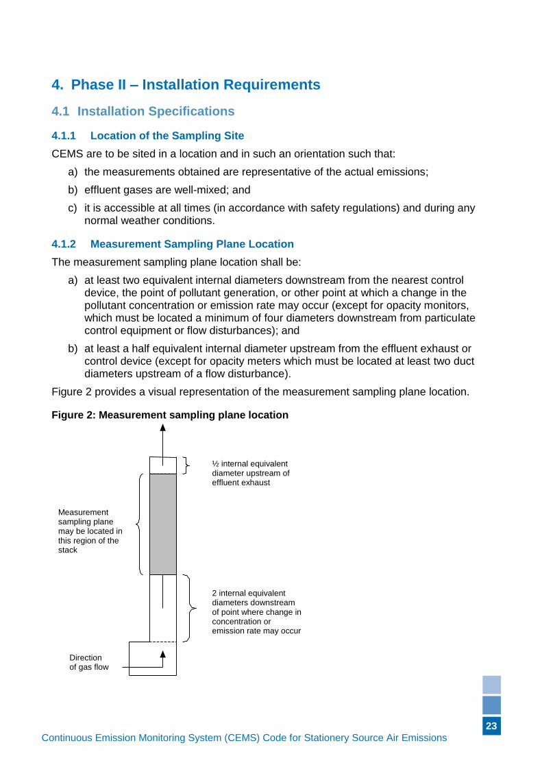
4.1.2 Measurement Sampling Plane Location
The measurement sampling plane location shall be:
a) at least two equivalent internal diameters downstream from the nearest control device, the point of pollutant generation, or other point at which a change in the pollutant concentration or emission rate may occur (except for opacity monitors, which must be located a minimum of four diameters downstream from particulate control equipment or flow disturbances); and
b) at least a half equivalent internal diameter upstream from the effluent exhaust or control device (except for opacity meters which must be located at least two duct diameters upstream of a flow disturbance).
Figure 2 provides a visual representation of the measurement sampling plane location.
Figure 2: Measurement sampling plane location
½ internal equivalent diameter upstream of effluent exhaust
2 internal equivalent diameters downstream of point where change in concentration or emission rate may occur
Measurement sampling plane may be located in this region of the stack
Direction of gas flow
24
Continuous Emission Monitoring System (CEMS) Code for Stationery Source Air Emissions (Version if applicable)
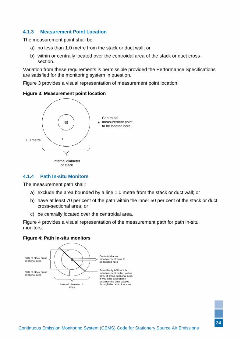
4.1.3 Measurement Point Location
The measurement point shall be:
a) no less than 1.0 metre from the stack or duct wall; or
b) within or centrally located over the centroidal area of the stack or duct cross-section.
Variation from these requirements is permissible provided the Performance Specifications are satisfied for the monitoring system in question.
Figure 3 provides a visual representation of measurement point location.
Figure 3: Measurement point location
Internal diameter of stack
1.0 metre
Centroidal measurement point to be located here
4.1.4 Path In-situ Monitors
The measurement path shall:
a) exclude the area bounded by a line 1.0 metre from the stack or duct wall; or
b) have at least 70 per cent of the path within the inner 50 per cent of the stack or duct cross-sectional area; or
c) be centrally located over the centroidal area.
Figure 4 provides a visual representation of the measurement path for path in-situ monitors.
Figure 4: Path in-situ monitors
internal diameter of stack
Centroidal area measurement point to be located here
50% of stack cross sectional area
Even if only 60% of this measurement path is within 50% of cross-sectional area, it would be acceptable because the path passes through the centroidal area
50% of stack cross sectional area
25
Continuous Emission Monitoring System (CEMS) Code for Stationery Source Air Emissions (Version if applicable)
4.1.5 Oxygen and Carbon Dioxide Dilution Monitors
Oxygen and carbon dioxide dilution monitors shall sample at the same point avoiding probe interference as the gas monitors, such as SO2. Alternatively, the dilution monitors shall be located at a position that is in close proximity to the gas monitors and such that the representativeness of the measurements is not compromised by any ingress air effects.
4.1.6 Opacity Monitors
Opacity monitors shall be located:
a) downstream of particulate control devices;
b) to ensure water droplets (condensation) are not present at the monitoring location; and
c) where light is not present – such as away from the stack exit and places where light leaks into the stack – to ensure the monitor does not respond to ambient light.
4.1.7 Flow Monitors
Checks for non-cyclonic or non-swirling flow conditions shall be made to ensure the suitability of the sampling site. Wind tunnel calibration of flow-measuring devices should be carried out before initial installation.
4.1.8 Operational Temperature Range
The CEMS equipment must be able to operate, as per the required specifications, in any ambient environmental condition under which the plant will be operating. At a minimum, the ambient environmental range is considered to be –5°C to +50°C. If necessary, air conditioning units (or other temperature control device) shall be installed to ensure the analysers and their components are maintained at a suitable ambient temperature for operation.
4.1.9 Representativeness
The sampling probe or in-situ analyser must be installed in a location where effluent gases are well-mixed. If this requirement is not satisfied, then the degree of stratification shall be quantified by conducting the
26
Continuous Emission Monitoring System (CEMS) Code for Stationery Source Air Emissions (Version if applicable)
Stratification Test Procedure described in this CEMS Code (see Section 0).
4.1.10 Other Monitors
Gas monitors not specified elsewhere shall satisfy all applicable requirements of Sections 4.1.1 through 4.1.4 (inclusive) and Sections 4.1.8 and 4.1.9.
4.2 Test procedures for Verifying Installation Specifications
Test procedures required for demonstrating compliance with relevant performance specification are described below.
27
Continuous Emission Monitoring System (CEMS) Code for Stationery Source Air Emissions (Version if applicable)
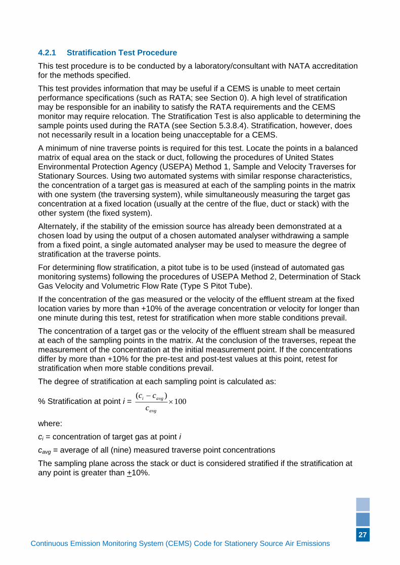
4.2.1 Stratification Test Procedure
This test procedure is to be conducted by a laboratory/consultant with NATA accreditation for the methods specified.
This test provides information that may be useful if a CEMS is unable to meet certain performance specifications (such as RATA; see Section 0). A high level of stratification may be responsible for an inability to satisfy the RATA requirements and the CEMS monitor may require relocation. The Stratification Test is also applicable to determining the sample points used during the RATA (see Section 5.3.8.4). Stratification, however, does not necessarily result in a location being unacceptable for a CEMS.
A minimum of nine traverse points is required for this test. Locate the points in a balanced matrix of equal area on the stack or duct, following the procedures of United States Environmental Protection Agency (USEPA) Method 1, Sample and Velocity Traverses for Stationary Sources. Using two automated systems with similar response characteristics, the concentration of a target gas is measured at each of the sampling points in the matrix with one system (the traversing system), while simultaneously measuring the target gas concentration at a fixed location (usually at the centre of the flue, duct or stack) with the other system (the fixed system).
Alternately, if the stability of the emission source has already been demonstrated at a chosen load by using the output of a chosen automated analyser withdrawing a sample from a fixed point, a single automated analyser may be used to measure the degree of stratification at the traverse points.
For determining flow stratification, a pitot tube is to be used (instead of automated gas monitoring systems) following the procedures of USEPA Method 2, Determination of Stack Gas Velocity and Volumetric Flow Rate (Type S Pitot Tube).
If the concentration of the gas measured or the velocity of the effluent stream at the fixed location varies by more than +10% of the average concentration or velocity for longer than one minute during this test, retest for stratification when more stable conditions prevail.
The concentration of a target gas or the velocity of the effluent stream shall be measured at each of the sampling points in the matrix. At the conclusion of the traverses, repeat the measurement of the concentration at the initial measurement point. If the concentrations differ by more than +10% for the pre-test and post-test values at this point, retest for stratification when more stable conditions prevail.
The degree of stratification at each sampling point is calculated as:
% Stratification at point i = 100)(
avg
avgi
c
cc
where:
ci = concentration of target gas at point i
cavg = average of all (nine) measured traverse point concentrations
The sampling plane across the stack or duct is considered stratified if the stratification at any point is greater than +10%.
28
Continuous Emission Monitoring System (CEMS) Code for Stationery Source Air Emissions (Version if applicable)
5. Phase III – Performance Testing
5.1 Performance Specifications
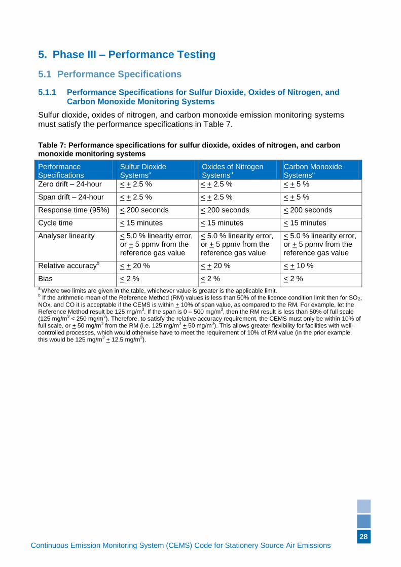
5.1.1 Performance Specifications for Sulfur Dioxide, Oxides of Nitrogen, and Carbon Monoxide Monitoring Systems
Sulfur dioxide, oxides of nitrogen, and carbon monoxide emission monitoring systems must satisfy the performance specifications in Table 7.
Table 7: Performance specifications for sulfur dioxide, oxides of nitrogen, and carbon monoxide monitoring systems
Performance Specifications
Sulfur Dioxide Systemsa
Oxides of Nitrogen Systemsa
Carbon Monoxide Systemsa
Zero drift – 24-hour < + 2.5 % < + 2.5 % < + 5 %
Span drift – 24-hour < + 2.5 % < + 2.5 % < + 5 %
Response time (95%) < 200 seconds < 200 seconds < 200 seconds
Cycle time < 15 minutes < 15 minutes < 15 minutes
Analyser linearity < 5.0 % linearity error, or + 5 ppmv from the reference gas value
< 5.0 % linearity error, or + 5 ppmv from the reference gas value
< 5.0 % linearity error, or + 5 ppmv from the reference gas value
Relative accuracyb < + 20 % < + 20 % < + 10 %
Bias < 2 % < 2 % < 2 % a Where two limits are given in the table, whichever value is greater is the applicable limit.
b If the arithmetic mean of the Reference Method (RM) values is less than 50% of the licence condition limit then for SO2,
NOx, and CO it is acceptable if the CEMS is within + 10% of span value, as compared to the RM. For example, let the Reference Method result be 125 mg/m
3. If the span is 0 – 500 mg/m
3, then the RM result is less than 50% of full scale
(125 mg/m3 < 250 mg/m
3). Therefore, to satisfy the relative accuracy requirement, the CEMS must only be within 10% of
full scale, or + 50 mg/m3 from the RM (i.e. 125 mg/m
3 + 50 mg/m
3). This allows greater flexibility for facilities with well-
controlled processes, which would otherwise have to meet the requirement of 10% of RM value (in the prior example, this would be 125 mg/m
3 + 12.5 mg/m
3).
29
Continuous Emission Monitoring System (CEMS) Code for Stationery Source Air Emissions (Version if applicable)
5.1.2 Performance Specifications for Total Reduced Sulfur and Hydrogen Sulfide Monitoring Systems
Total reduced sulfur and hydrogen sulfide monitoring systems must satisfy the performance specifications in Table 8.
Table 8: Performance specifications for total reduced sulfur and hydrogen sulfide monitoring systems
Performance Specifications
Total Reduced Sulfur Systemsa Hydrogen Sulfide Systemsa
Zero drift – 24-hour < + 5 % < + 5 %
Span drift – 24-hour < + 5 % < + 5 %
Response time (95%) < 200 seconds < 200 seconds
Cycle time < 15 minutes < 15 minutes
Analyser linearity < + 5 % < + 5 %
Relative accuracy < + 20 %, or < + 2 ppmv from the reference gas value
< + 20 %, or < + 2 ppmv from the reference gas value
Bias < 2 % < 2 %
a Where two limits are given in the table, whichever value is greater is the applicable limit.
5.1.3 Performance Specifications for Oxygen and Carbon Dioxide Monitoring Systems
Oxygen and carbon dioxide monitoring systems must satisfy the performance specifications in Table 9.
Table 9: Performance specifications for oxygen and carbon dioxide monitoring systems
Performance Specifications
Oxygen Monitorsa Carbon Dioxide Monitorsa
Zero drift – 24-hour < + 0.5 % O2 from the reference gas value
< + 0.5 % CO2 from the reference gas value
Span drift – 24-hour < + 0.5 % O2 from the reference gas value
< + 0.5 % CO2 from the reference gas value
Response time (95%) < 200 seconds < 200 seconds
Cycle time < 15 minutes < 15 minutes
Analyser linearity < 5.0 % linearity error or < + 0.5 % O2 from the reference gas value
< 5.0 % linearity error or < + 0.5 % CO2 from the reference gas value
Relative accuracy < + 10.0 %, or < + 1 % O2 from the reference gas value
< + 10.0 %, or < + 1 % CO2 from the reference gas value
Bias < 2 % < 2 % a Where two limits are given in the table, whichever value is greater is the applicable limit.
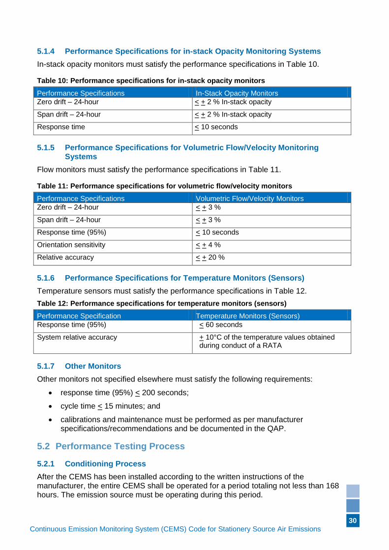
30
Continuous Emission Monitoring System (CEMS) Code for Stationery Source Air Emissions (Version if applicable)
5.1.4 Performance Specifications for in-stack Opacity Monitoring Systems
In-stack opacity monitors must satisfy the performance specifications in Table 10.
Table 10: Performance specifications for in-stack opacity monitors
Performance Specifications In-Stack Opacity Monitors
Zero drift – 24-hour < + 2 % In-stack opacity
Span drift – 24-hour < + 2 % In-stack opacity
Response time < 10 seconds
5.1.5 Performance Specifications for Volumetric Flow/Velocity Monitoring Systems
Flow monitors must satisfy the performance specifications in Table 11.
Table 11: Performance specifications for volumetric flow/velocity monitors
Performance Specifications Volumetric Flow/Velocity Monitors
Zero drift – 24-hour < + 3 %
Span drift – 24-hour < + 3 %
Response time (95%) < 10 seconds
Orientation sensitivity < + 4 %
Relative accuracy < + 20 %
5.1.6 Performance Specifications for Temperature Monitors (Sensors)
Temperature sensors must satisfy the performance specifications in Table 12.
Table 12: Performance specifications for temperature monitors (sensors)
Performance Specification Temperature Monitors (Sensors)
Response time (95%) < 60 seconds
System relative accuracy + 10°C of the temperature values obtained during conduct of a RATA
5.1.7 Other Monitors
Other monitors not specified elsewhere must satisfy the following requirements:
response time (95%) < 200 seconds;
cycle time < 15 minutes; and
calibrations and maintenance must be performed as per manufacturer specifications/recommendations and be documented in the QAP.
5.2 Performance Testing Process
5.2.1 Conditioning Process
After the CEMS has been installed according to the written instructions of the manufacturer, the entire CEMS shall be operated for a period totaling not less than 168 hours. The emission source must be operating during this period.
31
Continuous Emission Monitoring System (CEMS) Code for Stationery Source Air Emissions (Version if applicable)
During this Conditioning Process, the entire CEMS must operate normally, which means all processes of the entire system must work, including the measurement of the concentrations of the analytes and the other parameters such as flow. The only exceptions are for periods during which calibration procedures are being carried out, or other procedures as indicated in the QAP. Note that the data acquisition system forms an integral part of the overall system and must be fully operational during this period.
The system must output concentrations and emission rates of the analytes, or measurements of other parameters, in units as specified in the facility licence.
System modifications may be carried out, along with fine-tuning of the overall system, in preparation for the Operational Testing Process.
Daily calibration checks shall be conducted, and when the accumulated drift exceeds the daily control limits, the analysers shall be adjusted using the procedures defined in the CEMS QAP. The data acquisition system must reflect any calibration adjustments. Any automatic adjustments made in response to the daily zero and span checks must also be indicated in the data acquisition system.
If the Conditioning Process is interrupted as a result of a process shutdown, the times and dates of the shutdown period shall be recorded and the 168-hour test period shall be continued after the emission source has resumed operation.
If the monitor fails (i.e. breaks down) during the 168-hour time period, the Conditioning Process must be repeated, in full, after the system is repaired.
5.2.2 Operational Testing Process
When the Conditioning Process has been successfully completed, the CEMS must be operated for an additional 168-hour period during which the emission source is operating under typical conditions. This Operational Testing Process need not immediately follow the Conditioning Process.
The Performance Specification tests outlined in Section 5.1 must be conducted, and satisfied, for each CEMS during the Operational Testing Process, with the exception of the RATAs. RATAs may be conducted either during the Operational Testing Process or during the 168-hour period immediately following the Operational Testing Process. The tests are to be carried out under conditions that typify the day-to-day operation of the CEMS and must be described in the QAP.
During the Operational Testing Process, the CEMS must continue to measure the analytes and other parameters without interruption and produce a permanent record, using the data acquisition system, of the emission data. Sampling may be interrupted during this test period only to carry out system calibration checks and specified procedures as contained in the QAP.
During this period, no unscheduled maintenance, repairs, or adjustments should be carried out. Calibration adjustments may be performed at 24-hour intervals, or more frequently, if specified by the manufacturer and stated in the QAP. Automatic zero and calibration adjustments made without operator intervention may be carried out at any time, but these adjustments must be documented by the data acquisition system.
32
Continuous Emission Monitoring System (CEMS) Code for Stationery Source Air Emissions (Version if applicable)
If the Operational Testing Process is interrupted because of facility/process unit shutdown, the times and dates of the test process should be recorded, and continued when the facility/process unit resumes operation (i.e. the cumulative time of the test period shall be 168 hours). If the Operational Testing Process is interrupted as a result of CEMS failure, the entire test process must be restarted after the problem has been rectified (i.e. the 168-hour test period is reset to start at zero hours).
5.3 Test Procedures for Verifying Performance Specifications
The test procedures required for demonstrating compliance with the relevant performance specifications are described below.
5.3.1 Zero and Span Drift – 24-hour Tests for Gas and Dilution Monitoring Systems
For those systems that are not designed for the dynamic use of reference calibration gases, alternative protocols consistent with the manufacturer recommendations may be used in place of the following. These alternative procedures shall be included and detailed in the facility QAP.
For systems capable of automated calibrations the data system shall record the ‘as found’ and ‘as left’ values including a time stamp (date and time). If strip chart recorder data are reported, any automatic calibration adjustments must be noted on the strip chart recorder.
Automatic or manual calibration adjustments may be carried out each day, if required, however the Zero and Span Drift 24-hour tests must be conducted immediately before these adjustments, or in such a manner that the magnitude of the drifts can be determined.
At approximately 24-hour intervals for seven consecutive days, perform the calibration drift tests using a zero gas, or low-level (0 per cent to 20 per cent of span) concentration reference calibration gas, and a high-level (80 per cent to 100 per cent of span) concentration reference calibration gas.
With dual span CEMS, the above procedure must be conducted on both concentration ranges.
Operate each monitor in its normal sampling mode. For testing during the Operational Testing Process the process unit must be operating at 50% or greater of maximum load. For extractive and dilution type monitors, pass the audit gas through all filters, scrubbers, conditioners and other monitor components used during normal sampling and through as much of the sampling probe as is practical. For in-situ-type monitors, perform calibration by checking all active electronic and optical components, including the transmitter, receiver, and analyser.
The Zero and Span Drift 24-hour Test is conducted as described below.
The day prior to the seven-day test period:
1. Introduce zero gas or low-level reference calibration gas into the system, and zero the analyser.
2. Introduce the high-level reference calibration gas, and calibrate the system to this value.
33
Continuous Emission Monitoring System (CEMS) Code for Stationery Source Air Emissions (Version if applicable)
Day one:
3. Wait 24 hours (to the extent possible), then introduce the zero gas to the system and record the CEMS system value from the data acquisition system. After the CEMS value is recorded adjustments may be made to bring the zero-value of the system into calibration, if required.
4. Inject the high-level reference calibration gas, and record the CEMS system value. After the CEMS value is recorded adjustments may be made to bring the span-value of the system into calibration, if required.
Days two through seven:
5. Repeat steps 3 and 4 daily for the remaining six days of the test process.
For automated systems ensure the testing is performed before the system performs the calibration in order to determine the true drift value.
5.3.1.1 Calculations
Determine the calibration drift, for both the zero and span, once each day, at 24-hour intervals, for the seven consecutive days according to the following calculation:
Calibration Drift (%) = 100)(
S
AR
where:
R = the actual value of the calibration gas reference standard
A = the value of the reference standard, as measured and reported by the CEMS system
S = the span value of the CEM system component.
In order to satisfy the Operational Testing Process, the applicable performance specification must not be exceeded for any one day of the seven-day test period.
5.3.2 Zero and Span 24-hour Drift Test for Opacity Monitors
Perform the zero and span checks as per the following procedures, using independent audit filters for the zero and span simulations.
The day prior to the seven-day test period:
1. On the day prior to the start of the Operational Testing Process, perform zero and span calibrations of the opacity monitor (“opacity initial reading”).
Day one:
2. Wait 24 hours (to the extent possible) after performing the calibrations in step 1, then measure and record the simulated-zero reading (“opacity 24 hours reading”).
3. Measure and record the simulated-span reading. The zero and span values are to be treated as a data pair. The new measured zero and span readings are taken as the initial readings for the next 24-hour period (becomes the new “opacity initial
reading”).
4. Zero and span adjustments, if required, may now be performed.
Days two through seven:
5. Repeat steps 2 through 4 for the remaining six days of the test process.
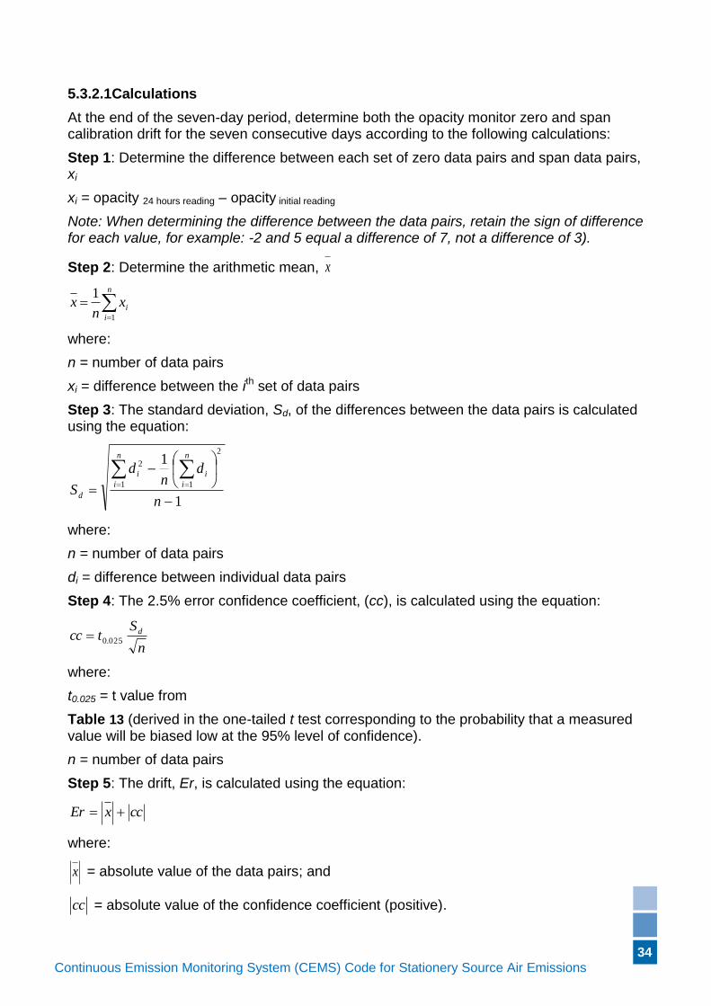
34
Continuous Emission Monitoring System (CEMS) Code for Stationery Source Air Emissions (Version if applicable)
5.3.2.1Calculations
At the end of the seven-day period, determine both the opacity monitor zero and span calibration drift for the seven consecutive days according to the following calculations:
Step 1: Determine the difference between each set of zero data pairs and span data pairs, xi
xi = opacity 24 hours reading – opacity initial reading
Note: When determining the difference between the data pairs, retain the sign of difference for each value, for example: -2 and 5 equal a difference of 7, not a difference of 3).
Step 2: Determine the arithmetic mean, x
n
i
ixn
x1
1
where:
n = number of data pairs
xi = difference between the ith set of data pairs
Step 3: The standard deviation, Sd, of the differences between the data pairs is calculated using the equation:
1
1
1
2
1
2
n
dn
d
S
n
i
n
i
ii
d
where:
n = number of data pairs
di = difference between individual data pairs
Step 4: The 2.5% error confidence coefficient, (cc), is calculated using the equation:
n
Stcc d
025.0
where:
t0.025 = t value from
Table 13 (derived in the one-tailed t test corresponding to the probability that a measured value will be biased low at the 95% level of confidence).
n = number of data pairs
Step 5: The drift, Er, is calculated using the equation:
ccxEr
where:
x = absolute value of the data pairs; and
cc = absolute value of the confidence coefficient (positive).
35
Continuous Emission Monitoring System (CEMS) Code for Stationery Source Air Emissions (Version if applicable)
In order to satisfy the Operational Testing Process, the calculated value, Er, must not exceed the applicable performance specification for each 24-hour period, or cumulatively over the seven-day period.
5.3.3 Zero and Span Calibration Drift 24-hour for Volumetric Flow/Velocity Monitors
Use the zero and span reference signals generated by the system for this test, following the procedures given in Section 5.3.1 (where, instead of reference calibration gas, read reference signal).
Once a day over the 168-hour Operational Test Period, introduce the flow monitor reference signals to the sensor, corresponding to zero (or low, 0 to 20% span) and high (80 to 100 per cent span) flow rates, and record the response of the monitor to each signal, as reported by the data acquisition system.
5.3.4 Flow Monitor Orientation Sensitivity
This test is intended for flow rate monitors that are sensitive to the orientation of the sensor in the gas flow, such as differential pressure flow sensors. Where possible, it is recommended that this test be carried out at three loads (rates):
a) minimum safe and stable operating load (rate);
b) approximately mid-load (rate) (40 to 60%); and
c) full load (rate) (90 to 100 per cent).
During a period of steady flow conditions at each load (rate), rotate the sensor in the gas flow a total of 10 degrees on each side of the zero degree position (directly into the gas flow, with no cyclonic flow patterns) in increments of 5 degrees, noting the response of the sensor at each angle. A total of five flows will be generated for each load (rate) condition, at -10, -5, 0, +5, +10 degrees relative to the zero-degree position.
For each flow rate generated, use the following formula to determine the orientation sensitivity:
Orientation sensitivity (%) =
100
zero
xzero
F
FF
where:
Fzero = the measured flow value at the zero degree position
Fx = the measured flow value at each of the incremental positions (-10, -5, +5, +10 degrees relative to the zero-degree position)
5.3.5 Response Time
Response time is to be determined as per Section 3.3.11.
5.3.6 Cycle Time
Cycle time is to be determined as per Section 3.3.12.
36
Continuous Emission Monitoring System (CEMS) Code for Stationery Source Air Emissions (Version if applicable)
5.3.7 Analyser Linearity
The analyser linearity test is to be performed using the test gases and procedures shown below.
For those systems that are not designed for the dynamic use of reference calibration gases, alternative protocols consistent with the manufacturer recommendations may be used in place of the following. These alternative procedures shall be included and detailed in the facility QAP.
5.3.7.1 Test Gases
Use reference calibration gases at low-level (0 to 20 per cent span), mid-level (40 to 60% span), and high-level (80 to 100% span) for each analyser. Dynamic or static dilution of a test gas to generate lower concentration standards is acceptable provided that the corresponding QA/QC plan/procedures are established and followed for the use of dynamic or static dilution systems.
5.3.7.2 Calibration Gas Injection Port
Test gases may be injected immediately before each analyser.
5.3.7.3 Procedures
The system must operate normally during the test, with all pressures, temperatures, and flows at nominal values. Introduce each test gas and allow the system response to stabilise, and then record the concentration of the reference calibration gas indicated by the data acquisition system output. Challenge the system three times with each gas, but do not use the same gas in succession. Instead, alternate the gases presented to the system.
With dual span CEMS, the above procedure must be conducted on both concentration ranges.
5.3.7.4 Calculations
Using the response values from data acquisition system, determine the linearity, at each of the low-range, mid-range, and high-range concentrations, according to the following calculation:
Linearity error (%) = 100
R
AR
where:
R = the actual value of each reference calibration gas; and
A = the average of the three system responses to each of the low- range, mid- range, or high-range reference calibration gases.
The Linearity Error must satisfy the specifications for each of the low- range, mid- range, and high-range tests.
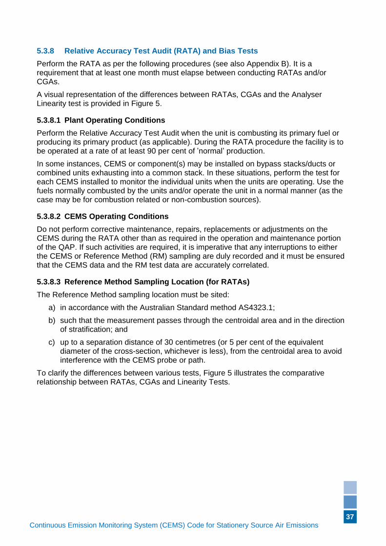
37
Continuous Emission Monitoring System (CEMS) Code for Stationery Source Air Emissions (Version if applicable)
5.3.8 Relative Accuracy Test Audit (RATA) and Bias Tests
Perform the RATA as per the following procedures (see also Appendix B). It is a requirement that at least one month must elapse between conducting RATAs and/or CGAs.
A visual representation of the differences between RATAs, CGAs and the Analyser Linearity test is provided in Figure 5.
5.3.8.1 Plant Operating Conditions
Perform the Relative Accuracy Test Audit when the unit is combusting its primary fuel or producing its primary product (as applicable). During the RATA procedure the facility is to be operated at a rate of at least 90 per cent of ’normal’ production.
In some instances, CEMS or component(s) may be installed on bypass stacks/ducts or combined units exhausting into a common stack. In these situations, perform the test for each CEMS installed to monitor the individual units when the units are operating. Use the fuels normally combusted by the units and/or operate the unit in a normal manner (as the case may be for combustion related or non-combustion sources).
5.3.8.2 CEMS Operating Conditions
Do not perform corrective maintenance, repairs, replacements or adjustments on the CEMS during the RATA other than as required in the operation and maintenance portion of the QAP. If such activities are required, it is imperative that any interruptions to either the CEMS or Reference Method (RM) sampling are duly recorded and it must be ensured that the CEMS data and the RM test data are accurately correlated.
5.3.8.3 Reference Method Sampling Location (for RATAs)
The Reference Method sampling location must be sited:
a) in accordance with the Australian Standard method AS4323.1;
b) such that the measurement passes through the centroidal area and in the direction of stratification; and
c) up to a separation distance of 30 centimetres (or 5 per cent of the equivalent diameter of the cross-section, whichever is less), from the centroidal area to avoid interference with the CEMS probe or path.
To clarify the differences between various tests, Figure 5 illustrates the comparative relationship between RATAs, CGAs and Linearity Tests.
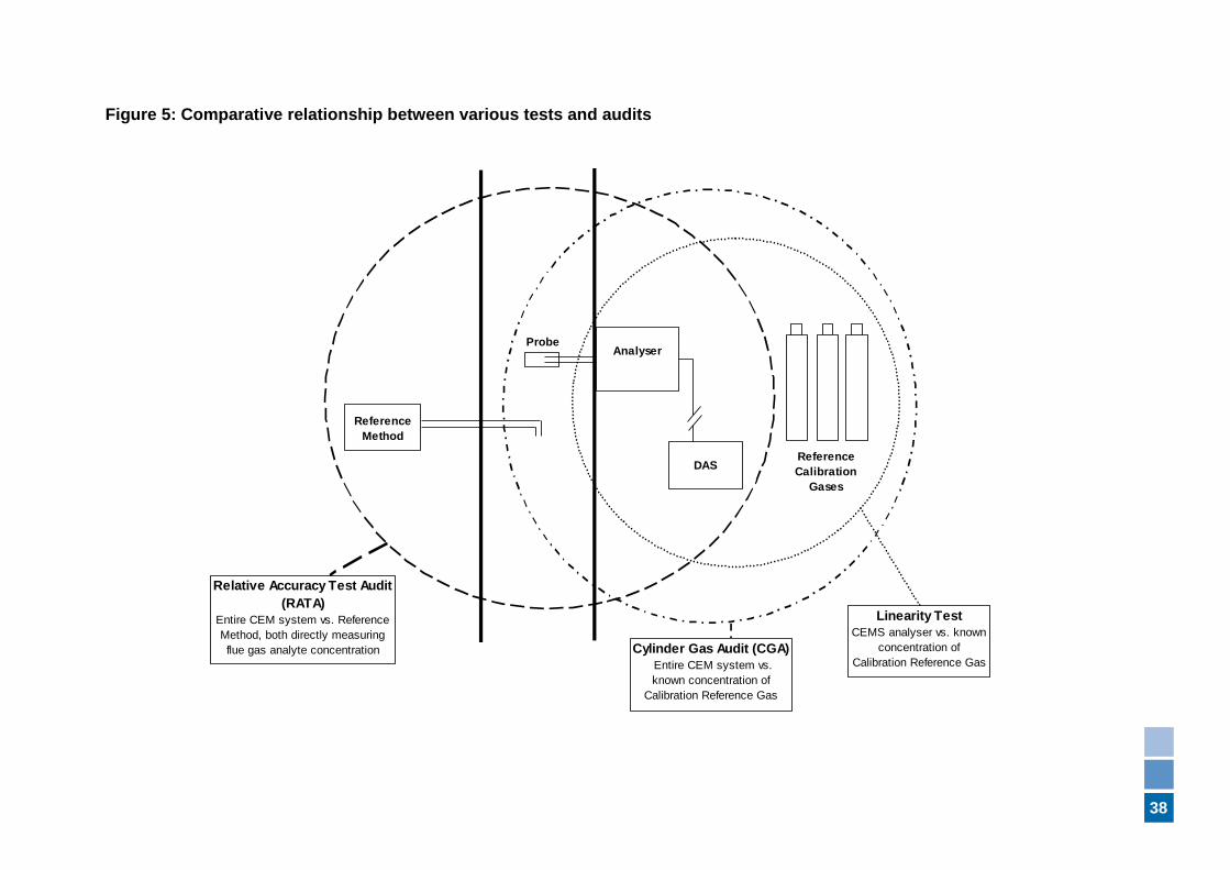
38
Figure 5: Comparative relationship between various tests and audits
AnalyserProbe
DAS
Reference
Method
Reference
Calibration
Gases
Relative Accuracy Test Audit
(RATA)
Entire CEM system vs. Reference
Method, both directly measuring
flue gas analyte concentration Cylinder Gas Audit (CGA)
Entire CEM system vs.
known concentration of
Calibration Reference Gas
Linearity Test
CEMS analyser vs. known
concentration of
Calibration Reference Gas
39
Continuous Emission Monitoring System (CEMS) Code for Stationery Source Air Emissions (Version if applicable)
5.3.8.4 Reference Method Sampling Points
During the conduct of a RATA, a minimum of three sampling points are used for the Reference Method tests.
The following describes the locations of the sampling points on the measurement (traverse) line:
a) for stack or ducts measuring less than or equal to 2.4 metre internal diameter, sampling points must be located at 16.7 per cent, 50 per cent and 83.3 per cent of the length of the line;
b) for stack or ducts measuring greater than 2.4 m internal diameter, and which the gases are non-stratified and the sampling plane is not downstream from a wet scrubber, and is not downstream of a location where gas streams of two different analyte concentrations combine, the sampling points may be located at positions 0.4 m, 1.2 m, and 2.0 m along the line (distances to be measured from the internal wall); and
c) for all other stacks, or ducts, measuring greater than 2.4 m internal diameter, the sampling points must be located at 16.7 per cent, 50 per cent and 83.3 per cent of the length of the line.
The tip of the Reference Method probe must be within 3cm of each indicated traverse point, but no closer than 3 cm to the wall of the stack or duct.
Where two or more probes are in the same proximity, care shall be taken to prevent probes from interfering with each other's sampling.
5.3.8.5 Reference Method Sampling Conditions
Conduct the Reference Method tests such that they will yield results representative of the pollutant concentration, emission rate, velocity, moisture content and temperature from the unit, and that the RM tests can be correlated with the CEMS measurements.
It is preferable to conduct the diluent (O2 or CO2) measurements and any moisture measurements that may be needed simultaneously with the analyte concentration measurements. However, diluent and moisture measurements taken within an hour of the target analyte measurement may be used to calculate dry pollutant and emission rates. Correlate individual CEMS data with the Reference Method data by marking the beginning and end of each Reference Method test run (including the exact time of day) on the data acquisition system, individual chart recorder(s) or other permanent recording device(s).
5.3.8.6 Consistency
CEMS and Reference Method test results are to be based on consistent moisture (i.e. dry), pressure, temperature, and diluent concentration and in the same units (standard temperature and pressure in Australia is 101.325 kPa and 0° Celsius). In addition, simultaneous measurements between the CEMS and the Reference Method are to be compared. Ensure the response times of the CEMS are taken into account when determining the simultaneous measurements (for example, if a system has a response time of 60 seconds, then the Reference Method will start a measurement at time X, and the CEMS will start recording the same measurement at time X+60 seconds). For time-shared systems, the use of applicable instrumental methods may be useful in ensuring
40
Continuous Emission Monitoring System (CEMS) Code for Stationery Source Air Emissions (Version if applicable)
data comparisons are accurate (time-shared systems may only measure for a few minutes at a time, which is insufficient duration for most manual tests). For use of non-instrumental methods with time-shared CEMS, ensure the tests can be conducted simultaneously with the requisite CEMS measurements and demonstrate the tests were concurrent through clock synchronisation, accurate recording of start/stop times, and other appropriate quality assurance/quality control activities.
For each RATA conducted, compare the measurements obtained from the CEMS via the data acquisition system (in ppmv, percentage CO2, or other units, as appropriate) against the corresponding Reference Method values. Display the paired data in a table.
5.3.8.7 Sampling Strategy
Reference Method sampling must be conducted by a consultant or laboratory with NATA accreditation for the required test method (see section 2.2 and Appendix B). Sampling is conducted simultaneously using both the CEMS and the Reference Method, thereby generating a paired set of CEMS and RM test data. A minimum of nine sets of paired monitoring and test data is required for each RATA. Each RM test (and corresponding CEMS measurements) shall take a minimum duration of 21 minutes. The RM sampling is conducted for equal time periods at each sampling point on the traverse.
For grab samples, take one sample at each traverse point (i.e. three separate measurements), at equal time intervals over a minimum span of 21 minutes (i.e. three samples, one at each point, each for seven minutes duration). The average of the three grab samples is considered to be the value for one test run.
If a Reference Method specifies a sampling period that is greater than 21 minutes, this requirement must be met; it is not acceptable to shorten the sampling period to 21 minutes, or any other sampling time. However, it is not a requirement to conduct all nine RATA test runs over one day (regardless of the sampling period time). If desired, a single RATA may be conducted over a two or three day period (if required by safety reasons, such as during storm events, more than three days are permitted).
The tester may choose to perform more than nine sets of Reference Method tests up to a total of 12 tests. If this option is chosen, the tester may reject a maximum of three sets of the test results, provided that an appropriate statistical test is applied to the data and it demonstrates that the results are outliers. The total number of test results used to determine the relative accuracy, or bias, must be greater than or equal to nine. All data must be reported, including the discarded outliers, along with the statistical test formula and all calculations.
5.3.8.8 Calculations
The paired test data from the Reference Method and the corresponding CEMS monitoring values are used for calculations. Ensure the values are comparable by correcting both sets of data to 0°C, 101.325 kPa, dry, and equivalent O2/CO2 dilution.
Step 1: For each data pair, calculate the difference, di using the equation:
di = RMi – CEMi
where:
RMi = reference method value for the ith data pair
CEMi = CEM system (monitor) value for the ith data pair
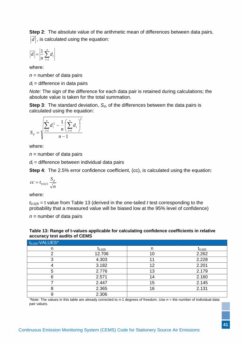
41
Continuous Emission Monitoring System (CEMS) Code for Stationery Source Air Emissions (Version if applicable)
Step 2: The absolute value of the arithmetic mean of differences between data pairs,
d , is calculated using the equation:
n
i
idn
d1
1
where:
n = number of data pairs
di = difference in data pairs
Note: The sign of the difference for each data pair is retained during calculations; the absolute value is taken for the total summation.
Step 3: The standard deviation, Sd, of the differences between the data pairs is calculated using the equation:
1
1
1
2
1
2
n
dn
d
S
n
i
n
i
ii
d
where:
n = number of data pairs
di = difference between individual data pairs
Step 4: The 2.5% error confidence coefficient, (cc), is calculated using the equation:
n
Stcc d
025.0
where:
t0.025 = t value from Table 13 (derived in the one-tailed t test corresponding to the probability that a measured value will be biased low at the 95% level of confidence)
n = number of data pairs
Table 13: Range of t-values applicable for calculating confidence coefficients in relative accuracy test audits of CEMS
t0.025-VALUES*
n t0.025 n t0.025
2 12.706 10 2.262
3 4.303 11 2.228
4 3.182 12 2.201
5 2.776 13 2.179
6 2.571 14 2.160
7 2.447 15 2.145
8 2.365 16 2.131
9 2.306 *Note: The values in this table are already corrected to n-1 degrees of freedom. Use n = the number of individual data pair values.
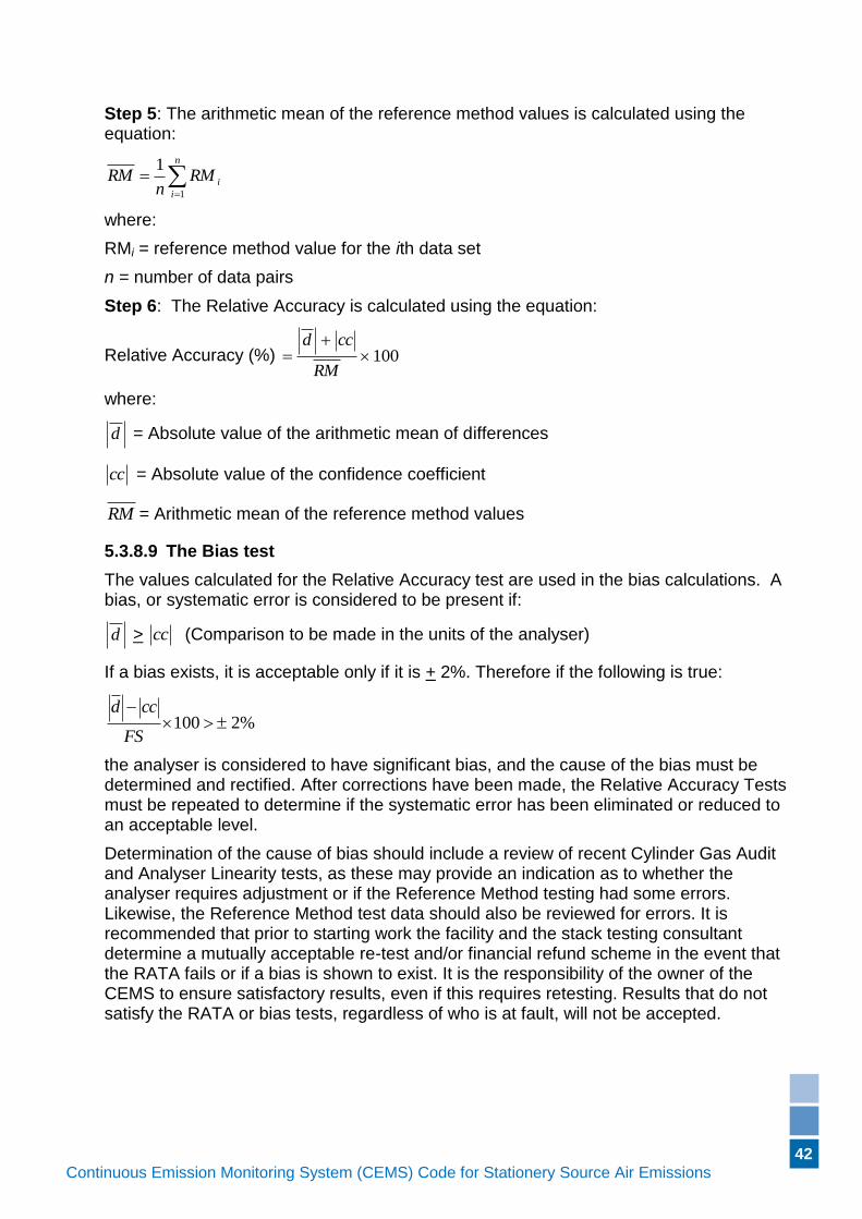
42
Continuous Emission Monitoring System (CEMS) Code for Stationery Source Air Emissions (Version if applicable)
Step 5: The arithmetic mean of the reference method values is calculated using the equation:
n
i
iRMn
RM1
1
where:
RMi = reference method value for the ith data set
n = number of data pairs
Step 6: The Relative Accuracy is calculated using the equation:
Relative Accuracy (%) 100
RM
ccd
where:
d = Absolute value of the arithmetic mean of differences
cc = Absolute value of the confidence coefficient
RM = Arithmetic mean of the reference method values
5.3.8.9 The Bias test
The values calculated for the Relative Accuracy test are used in the bias calculations. A bias, or systematic error is considered to be present if:
d > cc (Comparison to be made in the units of the analyser)
If a bias exists, it is acceptable only if it is + 2%. Therefore if the following is true:
%2100
FS
ccd
the analyser is considered to have significant bias, and the cause of the bias must be determined and rectified. After corrections have been made, the Relative Accuracy Tests must be repeated to determine if the systematic error has been eliminated or reduced to an acceptable level.
Determination of the cause of bias should include a review of recent Cylinder Gas Audit and Analyser Linearity tests, as these may provide an indication as to whether the analyser requires adjustment or if the Reference Method testing had some errors. Likewise, the Reference Method test data should also be reviewed for errors. It is recommended that prior to starting work the facility and the stack testing consultant determine a mutually acceptable re-test and/or financial refund scheme in the event that the RATA fails or if a bias is shown to exist. It is the responsibility of the owner of the CEMS to ensure satisfactory results, even if this requires retesting. Results that do not satisfy the RATA or bias tests, regardless of who is at fault, will not be accepted.
43
Continuous Emission Monitoring System (CEMS) Code for Stationery Source Air Emissions (Version if applicable)
5.3.9 Relative Accuracy Test for Flow Monitors
It is recommended, if possible, that the testing be carried out at the three loads (rates) as per Section 5.3.4.
Carry out a minimum of nine manual velocity traverse measurements at each load condition, as per Section 0. Calculate the Relative Accuracy for each load (rate) condition as shown in Section 5.3.8.8.
5.3.10 Relative Accuracy Test for Temperature Monitors (Sensors)
Temperature monitors (sensors) shall be verified using a certified reference thermometer or certified resistance temperature device (RTD)/readout or thermocouple/readout combination when conducting the RATA test. The RATA calculations do not apply to the temperature monitors, rather a simple comparison between the reading from the data acquisition system and the reading from the monitor/sensor used for the Reference Method being conducted at the time (for example while sampling for SO2, NOx) is used to ensure the CEMS is within the acceptable specification.
6. Phase IV – Ongoing Compliance Requirements
6.1 Ongoing CEMS Compliance Requirements
The following summarises the ongoing Quality Assurance/Quality Control compliance requirements for inspection, verification and calibration of CEMS. The procedures and activities used to fulfil these requirements must be documented in the QAP.
6.1.1 Ongoing Compliance Specifications and Frequency
The requirement for ongoing compliance commences upon successful completion of the Operational Testing Process.
The availability requirement for ongoing CEMS compliance is as detailed for the CEMS type and components listed in Column 1 of Table 14, and must be conducted for the specification and at the frequency detailed in Column 2 of Table 14.
The RATA performed during the Operational Testing Process counts towards the RATA requirement for the year (i.e. it is considered the first of the two RATAs required for the year).
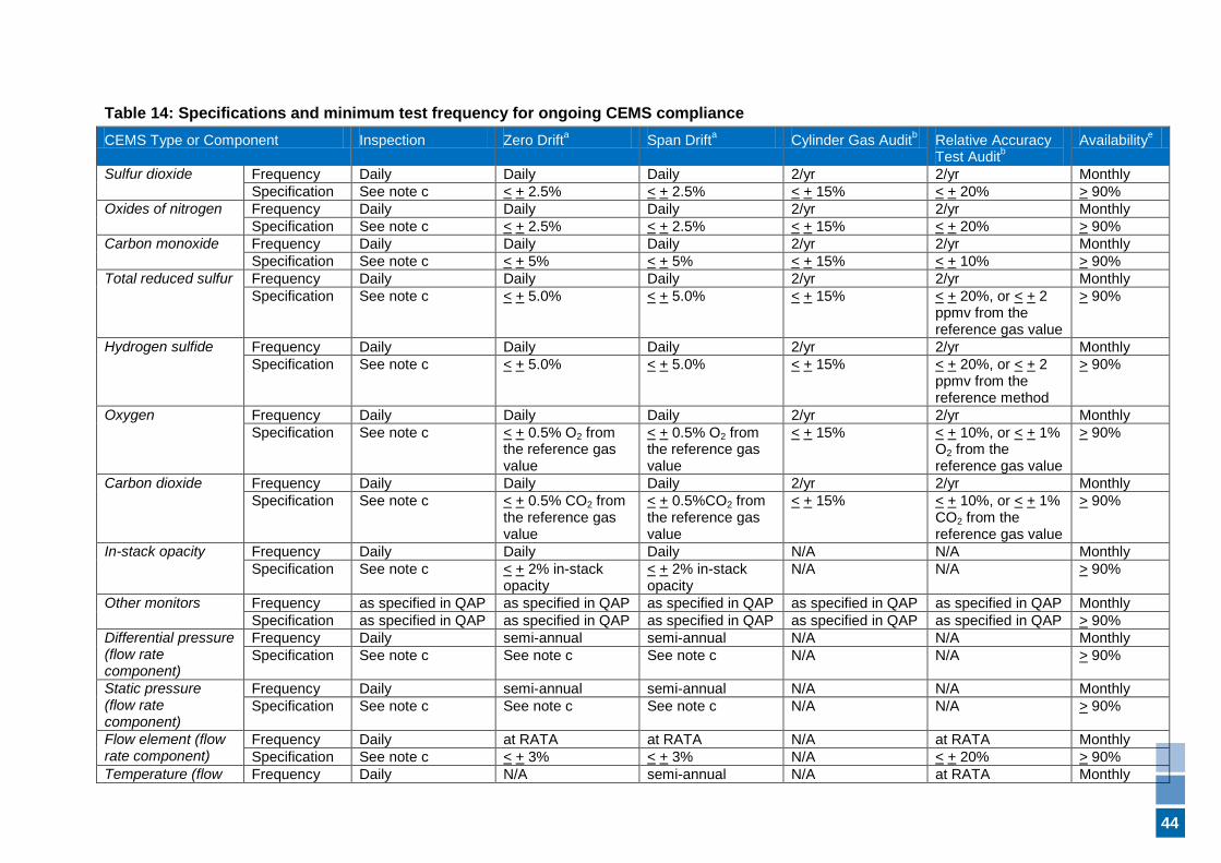
44
Table 14: Specifications and minimum test frequency for ongoing CEMS compliance
CEMS Type or Component Inspection Zero Drifta Span Drift
a Cylinder Gas Audit
b Relative Accuracy
Test Auditb
Availabilitye
Sulfur dioxide Frequency Daily Daily Daily 2/yr 2/yr Monthly
Specification See note c < + 2.5% < + 2.5% < + 15% < + 20% > 90%
Oxides of nitrogen Frequency Daily Daily Daily 2/yr 2/yr Monthly
Specification See note c < + 2.5% < + 2.5% < + 15% < + 20% > 90%
Carbon monoxide Frequency Daily Daily Daily 2/yr 2/yr Monthly
Specification See note c < + 5% < + 5% < + 15% < + 10% > 90%
Total reduced sulfur Frequency Daily Daily Daily 2/yr 2/yr Monthly
Specification See note c < + 5.0% < + 5.0% < + 15% < + 20%, or < + 2 ppmv from the reference gas value
> 90%
Hydrogen sulfide Frequency Daily Daily Daily 2/yr 2/yr Monthly
Specification See note c < + 5.0% < + 5.0% < + 15% < + 20%, or < + 2 ppmv from the reference method
> 90%
Oxygen Frequency Daily Daily Daily 2/yr 2/yr Monthly
Specification See note c < + 0.5% O2 from the reference gas value
< + 0.5% O2 from the reference gas value
< + 15% < + 10%, or < + 1% O2 from the reference gas value
> 90%
Carbon dioxide Frequency Daily Daily Daily 2/yr 2/yr Monthly
Specification See note c < + 0.5% CO2 from the reference gas value
< + 0.5%CO2 from the reference gas value
< + 15% < + 10%, or < + 1% CO2 from the reference gas value
> 90%
In-stack opacity Frequency Daily Daily Daily N/A N/A Monthly
Specification See note c < + 2% in-stack opacity
< + 2% in-stack opacity
N/A N/A > 90%
Other monitors Frequency as specified in QAP as specified in QAP as specified in QAP as specified in QAP as specified in QAP Monthly
Specification as specified in QAP as specified in QAP as specified in QAP as specified in QAP as specified in QAP > 90%
Differential pressure (flow rate component)
Frequency Daily semi-annual semi-annual N/A N/A Monthly
Specification See note c See note c See note c N/A N/A > 90%
Static pressure (flow rate component)
Frequency Daily semi-annual semi-annual N/A N/A Monthly
Specification See note c See note c See note c N/A N/A > 90%
Flow element (flow rate component)
Frequency Daily at RATA at RATA N/A at RATA Monthly
Specification See note c < + 3% < + 3% N/A < + 20% > 90%
Temperature (flow Frequency Daily N/A semi-annual N/A at RATA Monthly
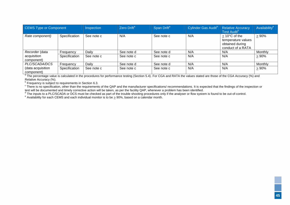
45
CEMS Type or Component Inspection Zero Drifta Span Drift
a Cylinder Gas Audit
b Relative Accuracy
Test Auditb
Availabilitye
Rate component) Specification See note c N/A See note c N/A + 10°C of the temperature values obtained during conduct of a RATA
> 90%
Recorder (data acquisition component)
Frequency Daily See note d See note d N/A N/A Monthly
Specification See note c See note c See note c N/A N/A > 90%
PLC/SCADA/DCS
(data acquisition component)
Frequency Daily See note d See note d N/A N/A Monthly
Specification See note c See note c See note c N/A N/A > 90%
a The percentage value is calculated in the procedures for performance testing (Section 5.4). For CGA and RATA the values stated are those of the CGA Accuracy (%) and
Relative Accuracy (%).
b Frequency is subject to requirements in Section 6.3.
c There is no specification, other than the requirements of the QAP and the manufacturer specifications/ recommendations. It is expected that the findings of the inspection or
test will be documented and timely corrective action will be taken, as per the facility QAP, whenever a problem has been identified. d The inputs to a PLC/SCADA or DCS must be checked as part of the trouble shooting procedures only if the analyser or flow system is found to be out-of-control.
e Availability for each CEMS and each individual monitor is to be > 90%, based on a calendar month.
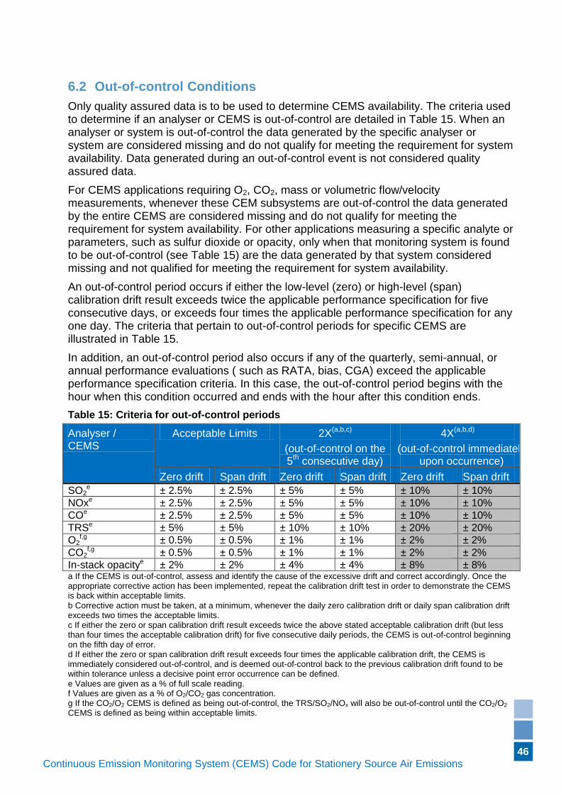
46
Continuous Emission Monitoring System (CEMS) Code for Stationery Source Air Emissions (Version if applicable)
6.2 Out-of-control Conditions
Only quality assured data is to be used to determine CEMS availability. The criteria used to determine if an analyser or CEMS is out-of-control are detailed in Table 15. When an analyser or system is out-of-control the data generated by the specific analyser or system are considered missing and do not qualify for meeting the requirement for system availability. Data generated during an out-of-control event is not considered quality assured data.
For CEMS applications requiring O2, CO2, mass or volumetric flow/velocity measurements, whenever these CEM subsystems are out-of-control the data generated by the entire CEMS are considered missing and do not qualify for meeting the requirement for system availability. For other applications measuring a specific analyte or parameters, such as sulfur dioxide or opacity, only when that monitoring system is found to be out-of-control (see Table 15) are the data generated by that system considered missing and not qualified for meeting the requirement for system availability.
An out-of-control period occurs if either the low-level (zero) or high-level (span) calibration drift result exceeds twice the applicable performance specification for five consecutive days, or exceeds four times the applicable performance specification for any one day. The criteria that pertain to out-of-control periods for specific CEMS are illustrated in Table 15.
In addition, an out-of-control period also occurs if any of the quarterly, semi-annual, or annual performance evaluations ( such as RATA, bias, CGA) exceed the applicable performance specification criteria. In this case, the out-of-control period begins with the hour when this condition occurred and ends with the hour after this condition ends.
Table 15: Criteria for out-of-control periods
Analyser / CEMS
Acceptable Limits 2X(a,b,c)
(out-of-control on the 5
th consecutive day)
4X(a,b,d)
(out-of-control immediately upon occurrence)
Zero drift Span drift Zero drift Span drift Zero drift Span drift
SO2e ± 2.5% ± 2.5% ± 5% ± 5% ± 10% ± 10%
NOxe ± 2.5% ± 2.5% ± 5% ± 5% ± 10% ± 10%
COe ± 2.5% ± 2.5% ± 5% ± 5% ± 10% ± 10%
TRSe ± 5% ± 5% ± 10% ± 10% ± 20% ± 20%
O2f,g ± 0.5% ± 0.5% ± 1% ± 1% ± 2% ± 2%
CO2f,g ± 0.5% ± 0.5% ± 1% ± 1% ± 2% ± 2%
In-stack opacitye ± 2% ± 2% ± 4% ± 4% ± 8% ± 8% a If the CEMS is out-of-control, assess and identify the cause of the excessive drift and correct accordingly. Once the appropriate corrective action has been implemented, repeat the calibration drift test in order to demonstrate the CEMS is back within acceptable limits. b Corrective action must be taken, at a minimum, whenever the daily zero calibration drift or daily span calibration drift exceeds two times the acceptable limits. c If either the zero or span calibration drift result exceeds twice the above stated acceptable calibration drift (but less than four times the acceptable calibration drift) for five consecutive daily periods, the CEMS is out-of-control beginning on the fifth day of error. d If either the zero or span calibration drift result exceeds four times the applicable calibration drift, the CEMS is immediately considered out-of-control, and is deemed out-of-control back to the previous calibration drift found to be within tolerance unless a decisive point error occurrence can be defined. e Values are given as a % of full scale reading. f Values are given as a % of O2/CO2 gas concentration. g If the CO2/O2 CEMS is defined as being out-of-control, the TRS/SO2/NOx will also be out-of-control until the CO2/O2 CEMS is defined as being within acceptable limits.
47
Continuous Emission Monitoring System (CEMS) Code for Stationery Source Air Emissions (Version if applicable)
6.2.1 Calibration Adjustment
A CEMS component must be calibrated whenever the observed inaccuracy exceeds the limits for that system component accuracy as specified in the Ongoing CEMS Compliance Requirements of Section 6.1.
A CEMS component need not be calibrated after each verification, rather only when it exceeds the specified tolerance.
6.3 Test Procedures for Ongoing Compliance
Test procedures required for demonstrating compliance with the relevant Ongoing Compliance Specifications are described below.
6.3.1 General Requirements (Applicability)
At least one month must elapse between conducting CGAs and/or RATAs.
6.3.1.1 Inspections
All CEMS components shall be inspected to verify that individual components have not failed and are operating within prescribed guidelines, such as requirements of this CEMS Code and manufacturer guidelines. The use of system components with integral fault detection diagnostics is highly desirable.
6.3.1.2 Zero and Span Drift 24-hour Tests
The Zero and Span Drift 24-hour Tests shall be conducted in accordance with the procedures of Section 5.3, as applicable. Tests are conducted and assessed daily; disregard instructions which are specific to the seven-day Operational Testing Process.
6.3.2 Temperature Measurement Verification
The temperature measurement shall be verified as per the procedures in Section 5.3.10.
6.3.3 Pressure Measurement Verification
The static pressure and differential measurement devices shall be verified using a certified manometer, dead weight tester or test gauge when conducting the RATA test.
6.3.4 Flow Element Verification
For pitot tube or similar systems visual inspection at turnaround or at least once per year, and as opportunities present themselves, shall be inspected for visible signs of plugging or damage. Wind tunnel calibration of flow-measuring devices should be carried out before initial installation, when visible damage has occurred, or when flow system inaccuracy exceeds acceptable tolerances and inaccuracy cannot be attributed to any component other than the flow element.
For pitot tube systems, if the following equation is true:
RA > ± 10%,
where:
RA refers to the relative accuracy,
48
Continuous Emission Monitoring System (CEMS) Code for Stationery Source Air Emissions (Version if applicable)
then pitot tubes must be removed and recalibrated unless the source of the error is found to be in the transmitter.
Back-purging (as necessary) of the primary flow measuring elements at an appropriate frequency is acceptable to ensure accurate data (and remove any build-up of materials), but should be performed when the analyser is being calibrated (or zeroed) so that the actual complete sampling time of both flow and analyte concentration is maximised.
For other flow methods, such as ultrasonic meters or anemometers, the QA/QC procedures and frequency shall be specified in a licence and documented in the facility QAP.
6.3.5 Data Acquisition System Verification
The inputs to the digital data acquisition system, such as PLC, DCS, SCADA or chart recorder must be verified using an appropriate calibrator as identified in the QAP.
6.3.6 Relative Accuracy Test Audit Procedures
The procedure for conducting the relative accuracy and bias tests is given in Section 0.
6.3.7 Cylinder Gas Audits
For Cylinder Gas Audits, the process unit and analyser system must be operating at normal conditions (for example pressure, temperature, flow rate, pollutant concentration). During the procedure the unit is to be operated at a rate of at least 90% of "normal" production. Normal production is defined as the average production or throughput for the facility.
The CGA procedure is conducted using the same procedures of the Analyser Linearity test of Section 0, with the following amendments:
a) the audit gas is to be introduced to the system at a location that results in the entire system being challenged (i.e. at the sampling probe). Systems that cannot accept audit gas at the probe must have the gas introduced at a location which challenges as much of the system as possible and this location must be documented in the QAP and specified in a licence;
b) the procedures followed for the CGA must be included and detailed in the QAP;
c) the following calculation is to be used to determine the result of the CGA:
100(%)
a
am
c
ccAccuracyCGA
where:
cm = average analyser response during the audit
ca = certified value of the reference calibration gas
For those systems that are not designed for the dynamic use of reference calibration gases, alternative protocols (such as audit gas cells) to be used in place of the cylinder gas audit must be specified in a licence. These alternative procedures shall be included and detailed in the facility QAP.
49
Continuous Emission Monitoring System (CEMS) Code for Stationery Source Air Emissions (Version if applicable)
6.3.8 Availability
The percentage availability for each monitor (system) shall be calculated monthly either by the data acquisition system, or manually, using the following equation:
% Availability (monitor or system) = 100T
Ta
where:
Ta = the time in hours during which the monitor (system) was generating quality assured data (as defined in section 1.1) during the time the source operated during the month.
T = the total time in hours the source operated during the month and is defined as those hours during which the fuel is burned*(for combustion-related processes) or those hours during which waste gases were being discharged from a source (for non-combustion-related sources).
* For combustion sources, the operational time also includes any time period(s) attributable to "cool down" or "purge" modes.
Time periods necessary for CEMS calibration, quality control checks or back-purging, shall not be considered as downtime when calculating Ta, as long as the minimum data averaging requirements for calibration and maintenance are satisfied (see Section 3.2.1(0).
The operational time or “availability” for both CEMS and each individual monitor shall be greater than or equal to 90 per cent, based on the calendar month.
6.3.9 Annual Evaluation
The CEMS and QAP must be evaluated every twelve months.
An auditor, knowledgeable in auditing procedures and in CEMS operations, and independent of the CEMS operation, must review the QAP, the CEMS operation, reports, and other associated records to determine if the procedures in the QAP are being followed. The auditor shall also note any changes in the system or the procedures since the last yearly evaluation and ensure that these have been included in the QAP.
The auditor shall report the findings and observations to the facility management. This report may include recommendations for improvements in the CEMS or its operation.
50
Continuous Emission Monitoring System (CEMS) Code for Stationery Source Air Emissions (Version if applicable)
7. Phase V – Reporting
7.1 General
The licensee shall make the QAP (and related Quality Control information generated as a result of the QAP) available for inspection and audit to DER upon request (normally as per relevant works approval or licence requirements).
7.2 CEMS Data Retention Requirements
Each facility shall retain the raw data (may be averaged into blocks consisting of a maximum of 10 minutes), all maintenance logs, corrective action logs and the QAP for a period of at least three years. "Summary" data is to be retained for a period of at least 10 years. Data shall be made available for inspection by DER upon request.
7.3 Quality Assurance Reporting Requirements
7.3.1 General Reporting
Reports shall include the following information:
a) licence (or works approval) number;
b) DER file number;
c) name under which the licence is issued;
d) company name or trade name;
e) address of premises;
f) postal address, if different from premises address;
g) page number and total number of pages; and
h) signature of authorised individual, certifying the report is true, accurate and representative, to the best of their knowledge, of the conditions that were assessed as required by the CEMS Code.
In regards to the Performance Specification and Performance Testing Process, reports shall also include the following reporting information:
i) a description of the activity or operation performed;
j) the date the activity or operation was performed;
k) the location at which the activity or operation was performed (e.g. stack 1)
l) the unique identification of the CEMS at which the activity or operation was performed (e.g. SO2 analyser X-123);
m) unambiguous identification of the method used (i.e. method number and title);
n) unambiguous identification of equipment and instruments used (e.g. unique identifier);
o) identification (for example initials) of the individual(s) performing the activity or operation; and
p) for test methods that require the use of calibration gases, detail the gas concentrations used for testing (for example CGA, Analyser Linearity);
51
Continuous Emission Monitoring System (CEMS) Code for Stationery Source Air Emissions (Version if applicable)
q) for test methods that introduce an audit gas, detail the location at which the audit gas was introduced into the system;
r) any external factors which may affect the quality or interpretation of the results;
s) any deviations or changes from the specified method;
t) any failures of the CEMS including a brief overview of the cause of the failure, and the corrective actions implemented to correct the problem and avoid recurrence of the failure;
u) the result of the testing and a comparison of the result against the specified criteria; and
v) all relevant data and calculations used in the conduct of the actual test(s).
7.3.2 Relative Accuracy Test Audit (RATA) Reporting
In addition to the requirements of Section 7.3.1, reports including the results of RATAs must detail the following:
a) all data, including any discarded outliers, along with the statistical test formula and all calculations (see Section 5.3.8.7);
b) a comparative table of both the CEMS and RATA test data collected for each of the test runs;
c) details of the sampling point location(s) and whether compliance with Sections 5.3.8.3 and 5.3.8.4 was achieved;
d) the Reference Method(s) used to conduct the RATA; and
e) the raw stack-testing data collected during the RATA.
Relative Accuracy Test Audit data must be reported at the highest resolution possible, but not to a greater resolution than one-minute intervals. For example, report the CEMS printout readings for every minute, and the RM printout for the same minute, if an online analyser method was used. If a wet-chemistry method was used, then it would be a comparison of the minute-by-minute CEMS data and the RM test run result for each individual run of manual testing.
7.3.3 Annual Evaluation
In addition to the requirements of Section 7.3.1, reports including the results of the Annual Evaluation must detail the following:
a) the start and completion date of the evaluation;
b) a general overview of the audit findings and recommendations; and
c) general information as to the response and corrective actions to the audit findings and recommendations, including a timeline as to when the actions will be completed.
Auxiliary documentation for the reports, as well as all other data records required for the facility QAP shall be retained at the facility site and be made available for inspection and audit by DER upon request.
52
Continuous Emission Monitoring System (CEMS) Code for Stationery Source Air Emissions (Version if applicable)
Appendix A: Quality Assurance Requirements
These requirements are not intended to limit the quality assurance and quality control practices necessary to ensure quality data.
1 General Requirements
1.1 A Quality Assurance program (QA program), shall be established, implemented and maintained, and the scope of the system should be commensurate with the size and scope of the monitoring program.
1.2 The Quality Assurance program shall be sufficient to ensure the accuracy, precision, quality and traceability of the data results required or generated by the monitoring program.
1.3 Documentation shall be sufficient to ensure the accuracy, precision, quality and traceability of the data results required or generated by the monitoring program.
1.4 Documentation shall be defined in a Quality Assurance Manual (however named). The information in the manual shall be understandable, available, accessible, and able to be implemented by the appropriate personnel.
1.5 An organisation chart shall be written which outlines the responsibilities and authorities of key individuals or groups within the company (it is sufficient to detail job titles on the chart, versus the names of individuals). This chart shall include the company personnel involved in aspects of the business which may affect the quality of the monitoring result(s).
2 Development, Approval and Issue of Documents
2.1 Procedures shall be written, maintained and implemented for the establishment, implementation and control of quality related documents.
2.2 All documents written as part of a QA program shall be reviewed and approved for use by authorised personnel.
2.3 Procedures shall be readily available and accessible to the personnel performing the operations.
2.4 Documents shall be uniquely identified with an identification number or code.
2.5 Documents shall include the date of issue.
2.6 Documents shall include a title, page number and total number of pages, and the name(s) of the person(s) who created and authorised the document.
2.7 Documents shall be periodically reviewed and revised, as necessary, to ensure they are still valid, appropriately descriptive and satisfy applicable requirements.
2.8 Original documents, such as master copies of procedures or forms, shall be retained and, when appropriate, suitably marked to indicate validity (e.g. mark out-of-service originals as ’obsolete’ or ‘superseded’).
2.9 Documents (including copies) shall be managed such that ones which are invalid or obsolete are removed from service, thereby avoiding unintended use.
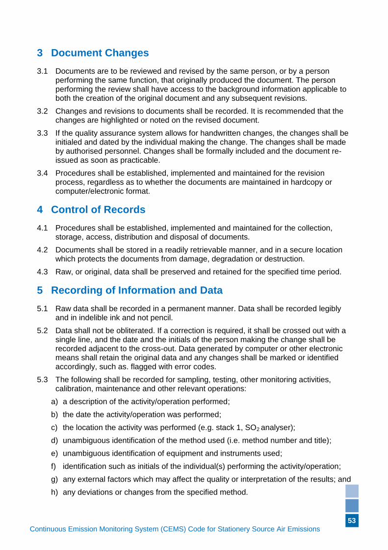
53
Continuous Emission Monitoring System (CEMS) Code for Stationery Source Air Emissions (Version if applicable)
3 Document Changes
3.1 Documents are to be reviewed and revised by the same person, or by a person performing the same function, that originally produced the document. The person performing the review shall have access to the background information applicable to both the creation of the original document and any subsequent revisions.
3.2 Changes and revisions to documents shall be recorded. It is recommended that the changes are highlighted or noted on the revised document.
3.3 If the quality assurance system allows for handwritten changes, the changes shall be initialed and dated by the individual making the change. The changes shall be made by authorised personnel. Changes shall be formally included and the document re-issued as soon as practicable.
3.4 Procedures shall be established, implemented and maintained for the revision process, regardless as to whether the documents are maintained in hardcopy or computer/electronic format.
4 Control of Records
4.1 Procedures shall be established, implemented and maintained for the collection, storage, access, distribution and disposal of documents.
4.2 Documents shall be stored in a readily retrievable manner, and in a secure location which protects the documents from damage, degradation or destruction.
4.3 Raw, or original, data shall be preserved and retained for the specified time period.
5 Recording of Information and Data
5.1 Raw data shall be recorded in a permanent manner. Data shall be recorded legibly and in indelible ink and not pencil.
5.2 Data shall not be obliterated. If a correction is required, it shall be crossed out with a single line, and the date and the initials of the person making the change shall be recorded adjacent to the cross-out. Data generated by computer or other electronic means shall retain the original data and any changes shall be marked or identified accordingly, such as. flagged with error codes.
5.3 The following shall be recorded for sampling, testing, other monitoring activities, calibration, maintenance and other relevant operations:
a) a description of the activity/operation performed;
b) the date the activity/operation was performed;
c) the location the activity was performed (e.g. stack 1, SO2 analyser);
d) unambiguous identification of the method used (i.e. method number and title);
e) unambiguous identification of equipment and instruments used;
f) identification such as initials of the individual(s) performing the activity/operation;
g) any external factors which may affect the quality or interpretation of the results; and
h) any deviations or changes from the specified method.
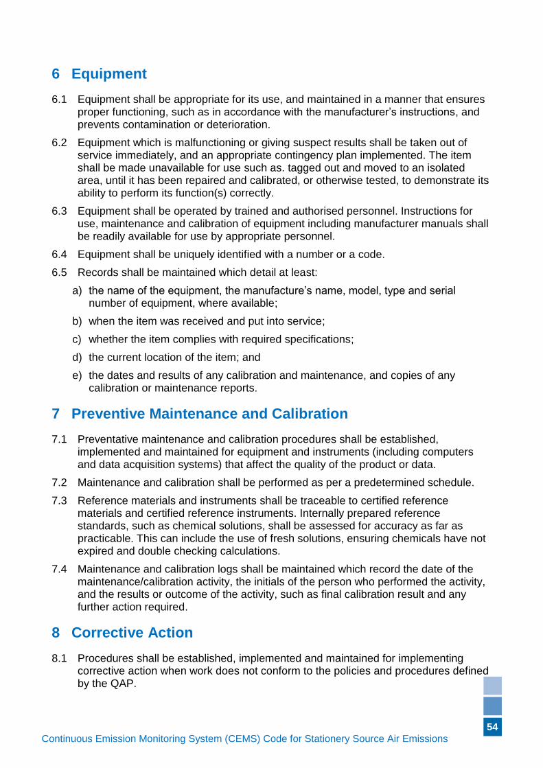
54
Continuous Emission Monitoring System (CEMS) Code for Stationery Source Air Emissions (Version if applicable)
6 Equipment
6.1 Equipment shall be appropriate for its use, and maintained in a manner that ensures proper functioning, such as in accordance with the manufacturer’s instructions, and prevents contamination or deterioration.
6.2 Equipment which is malfunctioning or giving suspect results shall be taken out of service immediately, and an appropriate contingency plan implemented. The item shall be made unavailable for use such as. tagged out and moved to an isolated area, until it has been repaired and calibrated, or otherwise tested, to demonstrate its ability to perform its function(s) correctly.
6.3 Equipment shall be operated by trained and authorised personnel. Instructions for use, maintenance and calibration of equipment including manufacturer manuals shall be readily available for use by appropriate personnel.
6.4 Equipment shall be uniquely identified with a number or a code.
6.5 Records shall be maintained which detail at least:
a) the name of the equipment, the manufacture’s name, model, type and serial number of equipment, where available;
b) when the item was received and put into service;
c) whether the item complies with required specifications;
d) the current location of the item; and
e) the dates and results of any calibration and maintenance, and copies of any calibration or maintenance reports.
7 Preventive Maintenance and Calibration
7.1 Preventative maintenance and calibration procedures shall be established, implemented and maintained for equipment and instruments (including computers and data acquisition systems) that affect the quality of the product or data.
7.2 Maintenance and calibration shall be performed as per a predetermined schedule.
7.3 Reference materials and instruments shall be traceable to certified reference materials and certified reference instruments. Internally prepared reference standards, such as chemical solutions, shall be assessed for accuracy as far as practicable. This can include the use of fresh solutions, ensuring chemicals have not expired and double checking calculations.
7.4 Maintenance and calibration logs shall be maintained which record the date of the maintenance/calibration activity, the initials of the person who performed the activity, and the results or outcome of the activity, such as final calibration result and any further action required.
8 Corrective Action
8.1 Procedures shall be established, implemented and maintained for implementing corrective action when work does not conform to the policies and procedures defined by the QAP.

55
Continuous Emission Monitoring System (CEMS) Code for Stationery Source Air Emissions (Version if applicable)
8.2 In the event of a non-conformance, investigation shall be conducted to determine the root cause and the effects of the problem, including effects on other outcomes or data, and potential corrective actions. The corrective action which is most likely to resolve the problem, and prevent it from recurring, is to be selected and implemented.
8.3 A corrective action report (however named) shall be written in the event of a non-conformance. The report shall record the results of the investigation and the chosen corrective action.
9 Training of Personnel
9.1 Procedures shall be established, implemented and maintained for the training and competency assessment of personnel.
9.2 Training records shall be established, implemented and maintained for training and assessment event(s). Records shall include the name of the trainee, date, the trainer’s initials, the scope of the training and the result (for example, if the person is authorised to perform task under supervision, or if supervision is not required).
9.3 Personnel undergoing training shall be supervised by appropriate and authorised staff until assessed as competent to routinely perform the desired task without supervision.
10 Service, Suppliers and Contractors
10.1 A policy and a procedure shall be established, implemented and maintained for the selection and purchasing of goods and services that can affect the quality of the product or data being produced. The selection of goods and services shall ensure services, suppliers and contractors are in compliance with the required specifications.
10.2 Purchased goods, such as consumables and reagents, which can affect the quality of the product or data being produced, shall be inspected or tested prior to use to ensure compliance with the required specifications.
11 Audits
11.1 Procedures shall be established, implemented and maintained for auditing activities and operations in order to verify that such activities and operations are being conducted in accordance with written procedures and the requirements of the QAP.
11.2 Audits shall be performed as per a predetermined schedule.
11.3 If any of the audit findings identify deviations from the requirements of the QAP, or identify concerns as to the effectiveness of the requirements, these deviations and/or concerns shall be recorded and the necessary corrective action implemented.
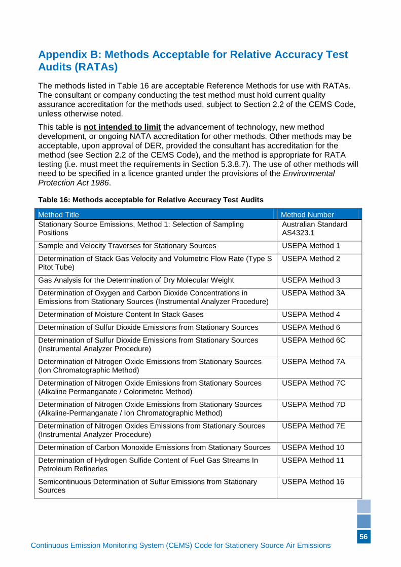
56
Continuous Emission Monitoring System (CEMS) Code for Stationery Source Air Emissions (Version if applicable)
Appendix B: Methods Acceptable for Relative Accuracy Test Audits (RATAs)
The methods listed in Table 16 are acceptable Reference Methods for use with RATAs. The consultant or company conducting the test method must hold current quality assurance accreditation for the methods used, subject to Section 2.2 of the CEMS Code, unless otherwise noted.
This table is not intended to limit the advancement of technology, new method development, or ongoing NATA accreditation for other methods. Other methods may be acceptable, upon approval of DER, provided the consultant has accreditation for the method (see Section 2.2 of the CEMS Code), and the method is appropriate for RATA testing (i.e. must meet the requirements in Section 5.3.8.7). The use of other methods will need to be specified in a licence granted under the provisions of the Environmental Protection Act 1986.
Table 16: Methods acceptable for Relative Accuracy Test Audits
Method Title Method Number
Stationary Source Emissions, Method 1: Selection of Sampling Positions
Australian Standard AS4323.1
Sample and Velocity Traverses for Stationary Sources USEPA Method 1
Determination of Stack Gas Velocity and Volumetric Flow Rate (Type S Pitot Tube)
USEPA Method 2
Gas Analysis for the Determination of Dry Molecular Weight USEPA Method 3
Determination of Oxygen and Carbon Dioxide Concentrations in Emissions from Stationary Sources (Instrumental Analyzer Procedure)
USEPA Method 3A
Determination of Moisture Content In Stack Gases USEPA Method 4
Determination of Sulfur Dioxide Emissions from Stationary Sources USEPA Method 6
Determination of Sulfur Dioxide Emissions from Stationary Sources (Instrumental Analyzer Procedure)
USEPA Method 6C
Determination of Nitrogen Oxide Emissions from Stationary Sources (Ion Chromatographic Method)
USEPA Method 7A
Determination of Nitrogen Oxide Emissions from Stationary Sources (Alkaline Permanganate / Colorimetric Method)
USEPA Method 7C
Determination of Nitrogen Oxide Emissions from Stationary Sources (Alkaline-Permanganate / Ion Chromatographic Method)
USEPA Method 7D
Determination of Nitrogen Oxides Emissions from Stationary Sources (Instrumental Analyzer Procedure)
USEPA Method 7E
Determination of Carbon Monoxide Emissions from Stationary Sources USEPA Method 10
Determination of Hydrogen Sulfide Content of Fuel Gas Streams In Petroleum Refineries
USEPA Method 11
Semicontinuous Determination of Sulfur Emissions from Stationary Sources
USEPA Method 16
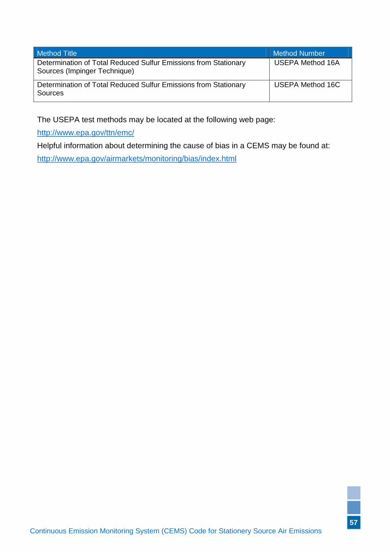
57
Continuous Emission Monitoring System (CEMS) Code for Stationery Source Air Emissions (Version if applicable)
Method Title Method Number
Determination of Total Reduced Sulfur Emissions from Stationary Sources (Impinger Technique)
USEPA Method 16A
Determination of Total Reduced Sulfur Emissions from Stationary Sources
USEPA Method 16C
The USEPA test methods may be located at the following web page:
http://www.epa.gov/ttn/emc/
Helpful information about determining the cause of bias in a CEMS may be found at:
http://www.epa.gov/airmarkets/monitoring/bias/index.html
58
Continuous Emission Monitoring System (CEMS) Code for Stationery Source Air Emissions (Version if applicable)
Appendix C: References for this Document
Alberta Environmental Protection. 1998. Continuous Emission Monitoring System (CEMS) Code. Edmonton, Alberta, Canada.
Environment Canada. 1993. Protocols and Performance Specifications for Continuous Monitoring of Gaseous Emissions from Thermal Power Generation. Report EPS 1/PG/7. Ottawa, Ontario.
U. S. Environmental Protection Agency. 2003. Code of Federal Regulations: Standards of Performance for New Stationary Sources. Appendix A - Test Methods. 40 CFR 60 Appendix A. Washington, D.C.
U. S. Environmental Protection Agency. 2003. Code of Federal Regulations: Standards of Performance for New Stationary Sources (Continued). Appendix B - Performance Specifications. 40 CFR 60 Appendix B. Washington, D.C.
Jahnke, James A., 2000, Continuous Emissions Monitoring, Second Edition, John Wiley & Sons, Inc., New York.