Context - Villanova Computer Sciencemdamian/Past/networksfa12/Notes/02DataLink.pdf · Q1: An...
41
The Data Link Layer Reading: Ch. 2.6, 3.1 2 Context Application Transport Network Data Link Ethernet Interface Application Presentation Session Transport Network (Data) Link Physical OSI TCP/IP Logical Link Media Access Control (MAC) Link Sublayers
Transcript of Context - Villanova Computer Sciencemdamian/Past/networksfa12/Notes/02DataLink.pdf · Q1: An...

The Data Link Layer
Reading: Ch. 2.6, 3.1
2
Context
Application
Transport
Network
Data Link Ethernet Interface
Application
Presentation
Session
Transport
Network
(Data) Link
Physical
OSI
TCP/IP
Logical Link
Media Access Control (MAC)
Link Sublayers

Message, Segment, Packet, and Frame
3
HTTP
TCP
IP
Ethernet interface
HTTP
TCP
IP
Ethernet interface
IP IP
Ethernet interface
Ethernet interface
SONET interface
SONET interface
host host
router router
HTTP message
TCP segment
IP packet IP packet IP packet
Ethernet frame Ethernet frame SONET frame
4
Physical node-to-node
bit-by-bit
Network host-to-host
Link node-to-node
frame-by-frame
101101001000100101010
The Link Layer
Packet
Frame

5
Link Layer Services
• Encoding
– Represent the 0s and 1s
• Framing
– Encapsulate packet into frame, adding header/trailer
• Error detection
– Receiver detecting errors with checksums
• Error correction
– Receiver optionally correcting errors
• Flow control
– Pacing between sending and receiving nodes
– Often omitted; provided at higher level (transport)
What is a Link?
6
Communication Medium Network Adapter

Link = Medium + Adapters
7
Adaptors Communicating
• Sending side – Encapsulates packet
in a frame
– Adds error checking bits, flow control, etc.
• Receiving side – Looks for errors, flow
control, etc.
– Extracts datagram and passes to receiving node
8
sending node
frame
receiving node
packet
frame
adapter adapter
link layer protocol packet

9
Simple Networks
• Multi-access link: Ethernet – Single physical link, shared by multiple nodes
• Point-to-point links: fiber-optic cable – Separate link per pair of nodes – Limitations on the number of adapters per node
multi-access link (broadcast network)
point-to-point links
Workstation Workstation
Workstation
Workstation Workstation
Workstation
10
Broadcast Networks (1)
• Bus topology
• Ethernet cable:
• All nodes share use of link, compete for access
. . .
10 Base 5
10Mbps Baseband (digital signalling)
Cable no longer than 500 m

11
Broadcast Networks (2)
• Star topology
• Fast Ethernet:
• The hub replicates the signal along all other links. (Switches are more common, and they forward frames only to the destination node.)
100 Base TX/FX
100Mbps Baseband (digital signalling)
Twisted Pairs / Fiber Optics
Hub
12
Broadcast Networks (3)
• Broadcast medium – All stations receive a copy of the message sent
– But most communication is intended to be only between two computers on a network
• To allow sender to specify destination, each station is assigned a hardware address (MAC address)
Sender Receiver
Signal propagates along the entire cable

13
Hardware Address (1)
• Example: Ethernet Addressing – Unique 48-bit MAC address
– First 24 bits is manufacturer code - assigned by IEEE
– Second 24 bits are sequentially assigned and UNIQUE
• Broadcast address: FF-FF-FF-FF-FF-FF
– Send the frame to all adapters
14
Hardware Address (2)
• Where is the MAC address stored ? – On the network adapter
– When the adapter is manufactured
• The network adapter – Handles packet transmission and reception
– It operates independently of the CPU
– Compares the destination MAC address on each incoming packet to the MAC address of its own station and discards frames not destined for the station
• Interface hardware, not software, checks address
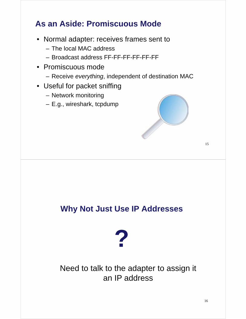
As an Aside: Promiscuous Mode
• Normal adapter: receives frames sent to – The local MAC address
– Broadcast address FF-FF-FF-FF-FF-FF
• Promiscuous mode – Receive everything, independent of destination MAC
• Useful for packet sniffing – Network monitoring
– E.g., wireshark, tcpdump
15
Why Not Just Use IP Addresses
?
16
Need to talk to the adapter to assign it an IP address

Who Am I: Acquiring an IP Address
17
71-65-F7-2B-08-53 1A-2F-BB-76-09-AD
0C-C4-11-6F-E3-98
???? 1.2.3.5
1.2.3.6
DHCP server
• Dynamic Host Configuration Protocol (DHCP) – Broadcast “I need an IP address, please!”
– Response “You can have IP address 1.2.3.4.”
Who Are You: Discovering the Receiver
• Address Resolution Protocol (ARP) – Broadcast “who has IP address 1.2.3.6?”
– Response “0C-C4-11-6F-E3-98 has 1.2.3.6!” 18
71-65-F7-2B-08-53 1A-2F-BB-76-09-AD
0C-C4-11-6F-E3-98
1.2.3.4 1.2.3.5
1.2.3.6

Sharing the Medium
Collisions
• Single shared broadcast channel – Avoid having multiple nodes speaking at once
– Otherwise, collisions lead to garbled data
20
71-65-F7-2B-08-53 1A-2F-BB-76-09-AD
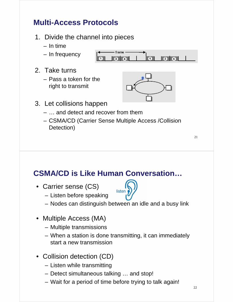
Multi-Access Protocols
1. Divide the channel into pieces – In time
– In frequency
2. Take turns – Pass a token for the
right to transmit
3. Let collisions happen – … and detect and recover from them
– CSMA/CD (Carrier Sense Multiple Access /Collision Detection)
21
• Carrier sense (CS) – Listen before speaking
– Nodes can distinguish between an idle and a busy link
• Multiple Access (MA) – Multiple transmissions
– When a station is done transmitting, it can immediately start a new transmission
• Collision detection (CD) – Listen while transmitting
– Detect simultaneous talking … and stop!
– Wait for a period of time before trying to talk again!
CSMA/CD is Like Human Conversation…
22

23
Effect of Propagation Delay on CSMA
carrier sense = idle
Transmit a packet
Collision
A B
packet
C
Propagation Delay: Time to propagate a packet from one end to other
24
Collision detection time How long does it take to realize there has been a collision?
Worst case: 2 x
To detect the collision, A must transmit for at least 2x time.
A B
Time=0
A B
Time=-
A B
Time=2
= end-to-end propagation
delay

Comparing the Three Approaches
• Channel partitioning – Efficient and fair at high load
– Inefficient at low load
• “Taking turns” – Eliminates empty slots without collisions
– Vulnerable to failures (e.g. lost token)
• CSMA/CD with Random access – Efficient at low load
– Collision overhead at high load
25
Ethernet (802.3)

27
Ethernet
• Dominant wired LAN technology
• First widely used LAN technology
• Kept up with speed race: 10 Mbps – 40 Gbps
Metcalfe’s Ethernet sketch
Ethernet Uses CSMA/CD
• Carrier Sense: wait for link to be idle – Channel idle: start transmitting
– Channel busy: wait until idle
• Collision Detection: listen while transmitting – No collision: transmission is complete
– Collision: abort transmission, and send jam signal
• Random Access: exponential back-off – Double the wait interval between each retransmission
attempt
28

29
Ethernet Backoff Algorithm
• Binary Exponential Backoff: – If collision, choose one slot randomly from 2k slots, where k
is the number of collisions the frame has suffered.
– This algorithm can adapt to changes in network load.
– Retries limited to 15 times (although k is capped at 10)
slot length = 2 x end-to-end delay
A B
30
Binary Exponential Backoff
slot length = 2 x end-to-end delay = 51.2 s
A B
t=0s: Assume A and B collide (kA = kB = 1) A, B choose randomly from 21 slots: [0,1] Assume A chooses 1, B chooses 1 t=100s: A and B collide (kA = kB = 2) A, B choose randomly from 22 slots: [0,3] Assume A chooses 2, B chooses 0 t=150s: B transmits successfully t=250s: A transmits successfully

Limitations on Ethernet Link Length
• Latency depends on physical length of link
• Suppose – A sends a packet at time t
– B sends packet just before t+
• Then A doesn’t see collision till t+2
• Imposes restrictions on Ethernet – Maximum distance between two nodes: 2500 meters
– Minimum length of the packet: 512 bits (64 bytes) 31
latency A B
32
Limitations on Ethernet Frame Length
• IEEE 802.3 specifies max value of 2 to be 51.2s – This relates to maximum distance of 2500m between hosts
– At 10Mbps it takes 0.1s to transmit one bit so 512 bits (64B) take 51.2s to send
• Condition for CSMA/CD to work:
Transmission Time > 2 – So Ethernet frames must be at least 64 bytes long
– Padding is used if data is less than 64 bytes
• Maximum frame length is 1500 bytes – So that the adaptor doesn’t occupy the line for too long

• Sending adapter encapsulates packet in frame
• Preamble: synchronization – Seven bytes with pattern 10101010, followed by one byte
with pattern 10101011
– Used to synchronize receiver, sender clock rates
Ethernet Frame Structure
33
Preamble Source
MAC address
Destination MAC
address Type CRC Data
Ethernet Frame Structure
• Addresses: source and destination MAC addresses – Adaptor passes frame to network-level protocol only if
destination is local MAC address or multicast/broadcast address or adapter is in promiscuous mode
– Otherwise, adapter discards frame
• Type: indicates the higher layer protocol – Usually IP, but also Novell IPX, AppleTalk, …
• CRC: cyclic redundancy check – Checked at receiver; if error, the frame is dropped
34
Preamble Source
MAC address
Destination MAC
address Type CRC Data

Unreliable, Connectionless Service
• Connectionless – No handshaking between send and receive adapter
• Unreliable – Receiving adapter doesn’t send ACKs or NACKs
– Packets passed to network layer can have gaps (which get filled in by the TCP transport protocol)
35
36
Ethernet – Questions:
Q1: An Ethernet MAC sublayer receives 42 bytes of data from the LLC sublayer. How many bytes of padding must be added to the data?
Q2: An Ethernet MAC sublayer receives 1510 bytes of data from the LLC sublayer. Can the data be encapsulated in one frame? If not, how many frames need to be sent ? What is the size of the data in each frame ?
37
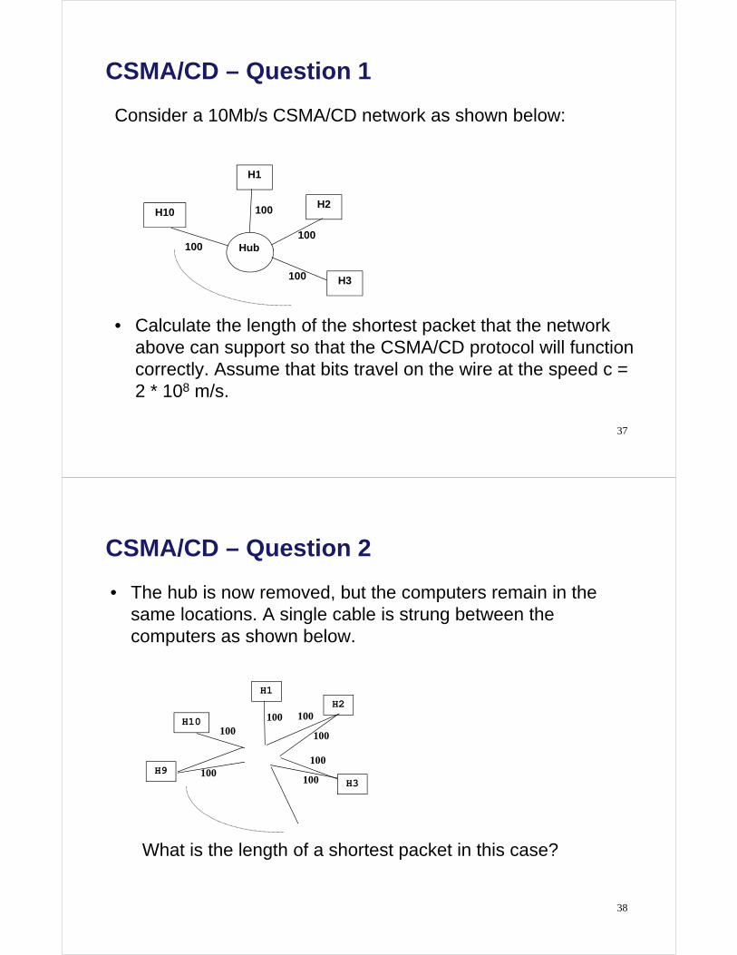
CSMA/CD – Question 1
Consider a 10Mb/s CSMA/CD network as shown below:
• Calculate the length of the shortest packet that the network above can support so that the CSMA/CD protocol will function correctly. Assume that bits travel on the wire at the speed c = 2 * 108 m/s.
H1
H2
H3
H10
Hub
100
100
100
100
38
CSMA/CD – Question 2
• The hub is now removed, but the computers remain in the same locations. A single cable is strung between the computers as shown below.
What is the length of a shortest packet in this case?
H1 H2
H10
H9
100 100
100
100
100 H3 100
100

39
CSMA/CD – Question 3
• Why do Ethernet adaptors select a random back-off time before trying to transmit a frame following a collision? Why do they pick the random back-off time from a larger range after each collision?
Extending Networks with
Interconnecting Devices

41
Interconnecting Devices
• There are many different interconnecting devices.
Ethernet
Router
Ethernet
Ethernet
Token- ring
Gateway
Bridge
Repeater
X.25 Network
42
Physical Layer: Repeaters
• Copy / Amplify signals between the two segments
• Analog devices, propagate valid signals as well as collisions
• Do not have hardware (MAC) addresses
• Ethernet allows at most 4 repeaters between 2 machines
Repeater
IP
LLC
802.3 MAC
IP
LLC
802.3 MACRepeater

43
Physical Layer: Hubs
• Joins multiple input lines electrically – Designed to hold multiple line cards
• Very similar to repeaters – Also operates at the physical layer
– Passive hubs may simply forward signals
– Active hubs may also amplify or refresh signals
4, 5, 8, 9, 16, 32, 64 Ports
44
Limitations of Repeaters and Hubs
• One large shared link – Each bit is sent everywhere
• Cannot support multiple LAN technologies – Does not buffer or interpret frames
– So, can’t interconnect between different rates or formats
– E.g., 10 Mbps Ethernet and 100 Mbps Ethernet
• Limitations on maximum nodes and distances – Shared medium imposes length limits
– E.g., cannot go beyond 2500 meters on Ethernet

45
Link Layer: Bridges/LAN Switches
• Interconnect multiple LANs, possibly of different types.
• Operate on frames, not signals.
• Have one or more NICs
BridgeToken-ring
BridgeIP
LLC
802.3 MAC 802.3 MAC 802.5 MAC
LLC
IP
LLC
802.5 MACLAN LAN
46
Bridges vs. LAN Switches
• A network switch is a computer networking device that connects network segments. The term commonly refers to a network bridge that processes and routes data at the Data link layer (layer 2) of the OSI model. One way to think of a layer 2 switch is as a multiport bridge.
• Switches that additionally process data at the Network layer (layer 3 and above) are often referred to as Layer 3 switches.
[Wikipedia] http://en.wikipedia.org/wiki/Network_switch

47
Bridge/LAN Switch Filtering
• Bridges learn from experience and build and maintain address tables of the nodes on the network.
– Extract destination address from the frame
– Look up the destination in a table
– Forward the frame to the appropriate LAN segment
• More about this later …
48
Advantages Over Hubs/Repeaters
• Only forward frames as needed
• Segments can support separate transmissions
• Can join segments using different technologies
hub hub hub
switch/bridge
segment segment segment
49
Disadvantages Over Hubs/Repeaters
• Delay in forwarding frames – Bridge/switch must receive and parse the frame
– … and perform a look-up to decide where to forward
– Storing and forwarding the packet introduces delay
– Solution: cut-through switching
• Need to learn where to forward frames – Bridge/switch needs to construct a forwarding table
– Ideally, without intervention from network administrators
– Solution: self-learning
• Higher cost – More complicated devices that cost more money
50
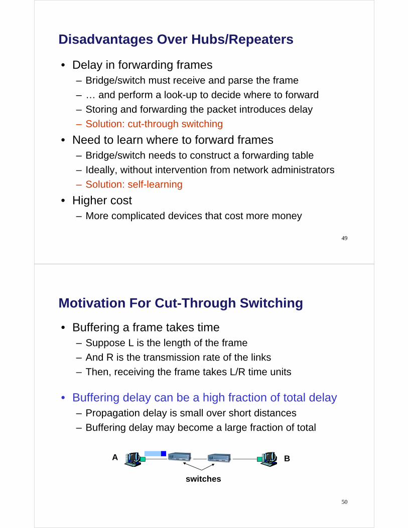
Motivation For Cut-Through Switching
• Buffering a frame takes time – Suppose L is the length of the frame
– And R is the transmission rate of the links
– Then, receiving the frame takes L/R time units
• Buffering delay can be a high fraction of total delay – Propagation delay is small over short distances
– Buffering delay may become a large fraction of total
A B
switches

51
Cut-Through Switching
• Start transmitting as soon as possible – Inspect the frame header and do the look-up
– If outgoing link is idle, start forwarding the frame
• Overlapping transmissions – Transmit the head of the packet via the outgoing link
– … while still receiving the tail via the incoming link
A B
switches
52
Learning Bridges
• What do bridges do if some LANs are reachable only in multiple hops ?
• What do bridges do if the path between two LANs is not unique ?
LAN 2
Bridge 2
LAN 5
LAN 3
LAN 1
LAN 4
Bridge 5
Bridge 4Bridge 3
d
Bridge 1

53
Transparent Bridges
• Not visible to end hosts
• Execute a spanning tree algorithm
• Two parts to transparent bridges: 1. Learning & Forwarding
2. Spanning Tree Algorithm
Bridge
LAN 5
LAN 3
LAN 1
LAN 4
Bridge
Bridge Bridge
Bridge
LAN 2
54
Transparent Bridges: Learning
• When a frame arrives – Inspect the source MAC address
– Associate the address with the incoming interface
– Store the mapping in the switch table
– Use a time-to-live field to refresh the mapping (default 15s)
A
B
C
D
Switch learns how to reach A.

55
Transparent Bridges: Forwarding (Miss)
• When frame arrives with unfamiliar destination – Forward the frame out all of the interfaces
– … except for the one where the frame arrived
– Hopefully, this case won’t happen very often
A
B
C
D
When in doubt, shout!
56
Transparent Bridges: Learning & Forwarding
When switch receives a frame:
Index switch table using MAC dest address
if entry found for destination then
{
if dest on segment from which frame arrived then
drop the frame
else
forward the frame on interface indicated
}
else flood
forward on all but the interface on which the frame arrived

57
Example
• Consider the following packets: (Src=A, Dest=F), (Src=C, Dest=A), (Src=E, Dest=C)
• What do the bridges learn?
Bridge 1
Port1
LAN 1
A
LAN 2
C B D
LAN 3
E F
Port2
Bridge 2
Port1 Port2
58
Danger of Loops
• Bridges sometimes need to broadcast frames – Upon receiving a frame with an unfamiliar destination
– Upon receiving a frame sent to the broadcast address
• Broadcasting can lead to loops – e.g., if the network contains a cycle of switches (reliability)

59
Loop Example (1) Bridge 1 Bridge 2
Host Port Host Port
A Top A Top
Bottom
60
Loop Example (2) Bridge 1 Bridge 2
Host Port Host Port
A Top A Bottom
Bottom

61
Solution: Spanning Trees
• Ensure the topology has no loops • Distributed algorithm constructing a spanning tree
– Sub-graph that covers all vertices but contains no cycles
– Switches cooperate to build the spanning tree
– … and adapt automatically when failures occur
62
Spanning Tree Algorithm - Key Ingredients
• Switches elect a “root” (smallest ID)
• Each switch identifies if its interface is on the shortest path from the root – And it exclude from the tree if not
• Switches collectively determine which interface is on a shortest path from a network segment to the root
• Configuration Messages (Y, d, X) – From bridge X
– Claiming Y is the root
– And the distance to root is d
root
one hop
three hops
BPDU (Bridge Protocol Data Unit)

Actual Information contained in BDPUs
63
64
Steps in Spanning Tree Algorithm
• Initially, each switch thinks it is the root – Switch sends a message out every interface
– … identifying itself as the root with distance 0
– Example: switch X announces (X, 0, X)
• Switches update their view of the root – Upon receiving a message, check the root id
– If the new id is smaller, start viewing that switch as root
• Switches compute their distance from the root – Add 1 to the distance received from a neighbor
– Identify interfaces not on a shortest path to the root
– … and exclude them from the spanning tree

65
Example From Switch #4’s Viewpoint
• Switch #4 thinks it is the root – Sends (4, 0, 4) message to 2 and 7
• Then, switch #4 hears from #2 – Receives (2, 0, 2) message from 2
– … and thinks that #2 is the root
• Then, switch #4 hears from #7 – Receives (2, 1, 7) from 7
– And realizes this is a longer path
– So, prefers its own one-hop path
– And removes 4-7 Iink from the tree (temporary view)
1
2
3 5
6 7
4
66
Example From Switch #4’s Viewpoint
• Switch #2 hears about switch #1 – Switch 2 hears (1, 1, 3) from 3
– Switch 2 starts treating 1 as root
– And sends (1, 2, 2) to neighbors
• Switch #4 hears from switch #2 – Switch 4 starts treating 1 as root
– And sends (1, 3, 4) to neighbors
• Switch #4 hears from switch #7 – Switch 4 receives (1, 3, 7) from 7
– And realizes this is a longer path
– So, prefers its own three-hop path
1
2
3 5
6 7
4

67
Root Ports and Designated Ports
• Each port attached to the spanning tree is a root port (RT) – Forwards frames towards the root as necessary
• Which bridge forwards frames to/from a LAN segment? – The one with a least cost path to the root
– Break ties by the lower bridge ID
– The port attaching that bridge to
the LAN segment is the
designated port for the LAN
• Blocked ports: – Each port that is not root
or designated is blocked
(does not receive or forward Ethernet frames)
1
2
3 5
6
7
4 RP
RP
RP RP
RP
RP
A
B
C
D
E
F
DP
DP
DP
DP
DP
DP
G
H
DP
DP
I DP
68
Spanning Tree Operation
• When the network has stabilized, it has converged and there is one spanning tree per network
• For every switched network the following elements exist: – One root bridge per network – One root port per non root bridge – One designated port per segment – Unused, non-designated (blocked) ports
• Root ports and designated ports forward data traffic • Non-designated (blocked) ports discard data traffic
– No addresses can be learned – Continue to receive and process BDPU packets
• so they can detect when an active path or device fails, and recalculate a new spanning tree

69
You Try It …
• Mark the Root, the Root Ports and the Designated Ports
70
Robust Spanning Tree Algorithm
• Algorithm must react to failures – Failure of the root node
• Need to elect a new root, with the next lowest identifier – Failure of other switches and links
• Need to recompute the spanning tree
• Root switch continues sending messages – Periodically reannouncing itself as the root (1, 0, 1) – Other switches continue forwarding messages
• every 2s by default
• Detecting failures through timeout (soft state!) – Switch waits to hear from others – Eventually times out and claims to be the root
See Section 3.1 in the textbook for details and another example

71
You Try It …
• If the link (4, 24) fails, what happens next?
72
Network Layer: Routers
• Router – A device that forwards data packets from one local area network (LAN) or wide area network (WAN) to another. Based on routing tables and routing protocols, routers read the network address in each transmitted frame and make a decision on how to send it based on the most expedient route (traffic load, line costs, speed, bad lines, etc.).
[TechWeb Encyclopedia]

73
Network Layer: Routers
Subnet-work
Router
Subnet-work
Router
Subnet-work
Application
TCP
IP
NetworkAccess
Application
TCP
IP
NetworkAccess
IP protocol IP protocol
DataLink
NetworkAccess
IP
NetworkAccess
NetworkAccess
IP
NetworkAccess
DataLink
DataLink
IP protocol
RouterRouter HostHost
74
Bridges vs. Routers (1)
• Bridges work at the data link layer, whereas routers work at the network layer.
• Bridges are faster than routers because they do not have to read the network protocol to get routing information.

75
Bridges vs. Routers (2)
• An enterprise network (e.g., university network) with a large number of local area networks (LANs) can use routers or bridges
• Until early 1990s: most LANs connected by routers
• Since mid1990s: LAN switches replace most routers
76
Internet
A Routed Enterprise Network
Router
Hubs
FDDI
FDDI

77
Internet
A Switched Enterprise Network
Router
Switch
78
Bridges vs. Routers (3)
Routers
• Each host’s IP address must be configured
• If network is reconfigured, IP addresses may need to be reassigned
• Routing done via protocols (RIP or OSPF)
• Each router manipulates packet IP header (e.g., reduces TTL field)
Bridges
• MAC addresses are hardwired
• No network configuration needed
• No routing protocol needed (sort of)
– learning bridge algorithm
– spanning tree algorithm

79
Comparing Hubs, Switches, Routers
Hub/
Repeater
Bridge/
Switch
Router
Traffic isolation
Plug and Play
Efficient routing
Cut through
no yes yes
yes yes no
no no yes
yes yes no
80
Transport Layer: Gateways
• Gateway – a computer that performs protocol conversion between different types of networks or applications. For example, a gateway can convert a TCP/IP packet to a NetWare IPX packet and vice versa, or from AppleTalk to DECnet, from SNA to AppleTalk and so on.
[TechWeb Encyclopedia]

81
This lecture
• Data Link Layer
– Transmission medium and adapters
• Multiple-Access (Broadcast) Networks
– Ethernet
• Interconnecting Devices
– Repeaters and hubs
– Bridges / LAN switches
– Routers
– Gateways