CONTENTS - ISRO file75 to 350 K 1.5 Maximum Allowable ... 1.6 1.24 Design code : ASME Process piping...
49
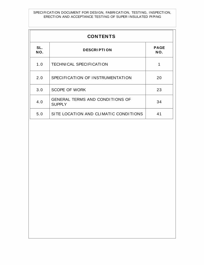
SPECIFICATION DOCUMENT FOR DESIGN, FABRICATION, TESTING, INSPECTION, ERECTION AND ACCEPTANCE TESTING OF SUPER INSULATED PIPING CONTENTS SL. NO. DESCRIPTION PAGE NO. 1.0 TECHNICAL SPECIFICATION 1 2.0 SPECIFICATION OF INSTRUMENTATION 20 3.0 SCOPE OF WORK 23 4.0 GENERAL TERMS AND CONDITIONS OF SUPPLY 34 5.0 SITE LOCATION AND CLIMATIC CONDITIONS 41
Transcript of CONTENTS - ISRO file75 to 350 K 1.5 Maximum Allowable ... 1.6 1.24 Design code : ASME Process piping...
SPECIFICATION DOCUMENT FOR DESIGN, FABRICATION, TESTING, INSPECTION, ERECTION AND ACCEPTANCE TESTING OF SUPER INSULATED PIPING
CONTENTS
SL. NO.
DESCRIPTION PAGE NO.
1.0 TECHNICAL SPECIFICATION 1
2.0 SPECIFICATION OF INSTRUMENTATION 20
3.0 SCOPE OF WORK 23
4.0 GENERAL TERMS AND CONDITIONS OF SUPPLY
34
5.0 SITE LOCATION AND CLIMATIC CONDITIONS 41

SPECIFICATION DOCUMENT FOR DESIGN, FABRICATION, TESTING, INSPECTION, ERECTION AND ACCEPTANCE TESTING OF SUPER-INSULATED (SI) PIPING.
1-TECHNICAL SPECIFICATION
1
1.0 DESIGN DATA
1.1 Piping layout : Super insulated (SI) pipelines as per
Preliminary Isometric piping layout
drawing No. SST/CTC/SI/L1 and
Tentative layout drawing for super
insulated piping (DN15, 160S) drawing
No. SST/CTC/SI/LY-01 enclosed.
1.2 Insulation : Evacuated multi-layer Super
Insulation (SI) with Aluminised or
silverised Mylar /Aluminum foil with
Glass fibre for pipe line. Removable
Polyurethane foam/ glass wool
insulation for flanged joints.
1.3 Service fluid :
Cold Gaseous Helium (GHe)
1.4
Working temperature
:
75 to 350 K
1.5 Maximum Allowable
Working Pressure
(MAWP)
: 40 MPa (a)
1.6 1.24 Design code
: ASME Process piping code B31.3
SPECIFICATION DOCUMENT FOR DESIGN, FABRICATION, TESTING, INSPECTION, ERECTION AND ACCEPTANCE TESTING OF SUPER-INSULATED (SI) PIPING.
1-TECHNICAL SPECIFICATION
2
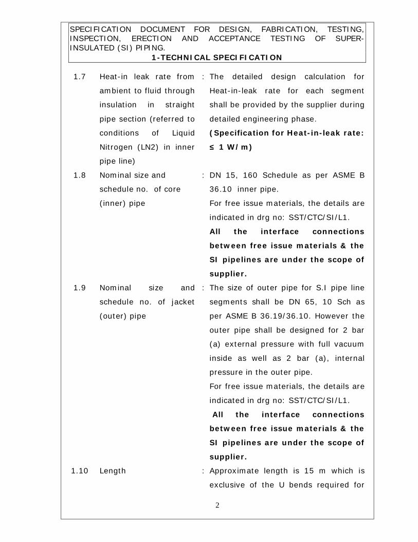
1.7 Heat-in leak rate from
ambient to fluid through
insulation in straight
pipe section (referred to
conditions of Liquid
Nitrogen (LN2) in inner
pipe line)
: The detailed design calculation for
Heat-in-leak rate for each segment
shall be provided by the supplier during
detailed engineering phase.
(Specification for Heat-in-leak rate:
≤ 1 W/m)
1.8 Nominal size and
schedule no. of core
(inner) pipe
: DN 15, 160 Schedule as per ASME B
36.10 inner pipe.
For free issue materials, the details are
indicated in drg no: SST/CTC/SI/L1.
All the interface connections
between free issue materials & the
SI pipelines are under the scope of
supplier.
1.9 Nominal size and
schedule no. of jacket
(outer) pipe
: The size of outer pipe for S.I pipe line
segments shall be DN 65, 10 Sch as
per ASME B 36.19/36.10. However the
outer pipe shall be designed for 2 bar
(a) external pressure with full vacuum
inside as well as 2 bar (a), internal
pressure in the outer pipe.
For free issue materials, the details are
indicated in drg no: SST/CTC/SI/L1.
All the interface connections
between free issue materials & the
SI pipelines are under the scope of
supplier.
1.10 Length : Approximate length is 15 m which is
exclusive of the U bends required for

SPECIFICATION DOCUMENT FOR DESIGN, FABRICATION, TESTING, INSPECTION, ERECTION AND ACCEPTANCE TESTING OF SUPER-INSULATED (SI) PIPING.
1-TECHNICAL SPECIFICATION
3
thermal compensation.
Actual length will be based on the
detailed isometric piping
fabrication drawings to be
prepared by the supplier from
piping layout drawing considering
‘U’ bends, site conditions and
changes during detailed
engineering & during erection.
However lumpsum cost should be
quoted considering all the above.
1.11 The relief pressure of
vacuum pump out port
cum seal off valve in
the vacuum jacket of
the each piping
segment
: As per standard & same shall be
submitted to purchaser during detailed
engineering phase for approval.
1.12 Pipes & Pipe fittings
: Seamless type. Butt weld fittings are
preferable for inner pipeline
1.13
Helium Leak Tightness
I) Individual joints/bellows of SI pipe lines:
II)
a) Inner pipe & Jacket
pipe weld joints
: ≤1 x 10⁻⁸ m bar l/s
b) Thread / flange joint, etc (other than weld joint)
:
≤1 x 10⁻⁵m bar l/s
c) Bellows : ≤1 x 10⁻⁸ m bar l/s

SPECIFICATION DOCUMENT FOR DESIGN, FABRICATION, TESTING, INSPECTION, ERECTION AND ACCEPTANCE TESTING OF SUPER-INSULATED (SI) PIPING.
1-TECHNICAL SPECIFICATION
4
1.14
II) Global leak of each pipe line segment (Each vacuum
cavity):
a) Atmosphere to
vacuum jacket
: ≤1 x 10⁻⁶ m bar l/s
b) Inner pipe to vacuum
jacket
: ≤1 x 10⁻⁷ m bar l/s
Stabilized vacuum level
in jacket (insulation) at
atmospheric
temperature
: ≤1x 10⁻² m bar
1.15 Materials of construction
v Pipes (Core and
jacket pipes),
seamless
v Bellows
:
:
ASTM A 312 TP 304 L / 316L / 321
SS 321/316 Ti/ Haste alloy
C276/Inconel
v Bellow Sleeves, pipe
stubs (seamless)
:
SS304L / 316L/ 321
v Adaptors for
temperature
indicator
:
SS304L / 316L/ 321
v Butt weld fittings
(seamless) : ASTM A 403 WP-S 304 L / 316L/321
v Flanges : ASTM A 182 F 304L / 316L/ 321
v Socket weld fittings
(seamless)
: ASTM A 182 F 304 L / 316L/ 321
v Bolts : ASTM A 193 B 8
v Nuts : ASTM A 194 Gr 8
v Multi layer insulation
: Multi layer insulation of Aluminized or
Silverised Mylar/ Aluminum foil with
glass fibre.

SPECIFICATION DOCUMENT FOR DESIGN, FABRICATION, TESTING, INSPECTION, ERECTION AND ACCEPTANCE TESTING OF SUPER-INSULATED (SI) PIPING.
1-TECHNICAL SPECIFICATION
5
v Spacers, suspensions : Suitable low thermal conductivity
material
1.16 Governing standards
Pipes : ASME B 36.19/ 36.10
Flanges : ASME B 16.5
Socket weld pipe fittings : ASME B 16.11
Butt weld pipe fittings : ASME B 16.9
1.17
.
Welding Process
All the welding both in the inner pipe as well as in the outer
vacuum jacket pipe shall be performed by Gas purged tungsten arc
welding (GTAW/TIG) with gaseous Argon (99.99% purity) purging.
All the welding at supplier’s works as well as at purchaser’s work
site shall be performed by qualified welders. The welding processes
shall comply with the requirements of Section IX, ASME. Welding
Procedure Specifications (WPS) shall be provided by the supplier.
The welding procedure qualification and welders’ performance
qualification (WPQ) shall be done as per Section IX, ASME. The
welder’s performance qualification (WPQ) certificate issued by a
competent authority shall be furnished.
During welding, temperature control near the weld joints
needs to be emphasized (i.e. temperature shall be ≤ 80 °C at the
distance of 100 mm from the joint being welded) in such a way
that any part of components (Eg. Temperature sensor, valve seat
etc.) in the pipeline next to the welding spot should not be affected.
The details of the same shall be provided by the supplier during
Detailed engineering review.

SPECIFICATION DOCUMENT FOR DESIGN, FABRICATION, TESTING, INSPECTION, ERECTION AND ACCEPTANCE TESTING OF SUPER-INSULATED (SI) PIPING.
1-TECHNICAL SPECIFICATION
6
1.18
1.19
Welding rods shall be chosen in accordance with the relevant
standards. Welding rods chosen shall be suitable for material of
free issue materials also. Supplier shall provide the details of
welding rods chosen during detailed engineering phase to the
purchaser for approval.
Thermal compensation
The following thermal compensation technique shall be employed,
Inner pipe shall be provided with bends at appropriate
locations to have thermal compensation. At those locations
the outer pipe shall be replaced with bellows.
The thermal compensation of the inner pipes upon chill-down shall
be taken care of by U bends. U bends are allowed in the inner pipe
lines at specific locations to relieve thermal loads. Bellows for outer
pipe shall be bought from reputed manufacturers; approval of the
same shall be got from purchaser during detailed engineering
phase. Drawings & Detailed design calculations with details such as
Axial expansion, length, cycles of operation, Axial spring rate,
Lateral spring rate, Torsional spring rate, Limiting internal design
pressure based on column instability, Limiting design pressure
based on in plane instability, Bellows effective area, stresses etc
(based on EJMA / relevant standards) for each type & size of
bellows shall be submitted to the purchaser for approval during
detailed engineering phase.
Individual segments & its Outer Jackets of SI pipe lines
As shown in the drawing No: SST/CTC/SI/L1 one segment
with line No: 604-15-160-40-SI is to be with flanged ends since
this has to be removable type. The remaining SI pipeline segments
SPECIFICATION DOCUMENT FOR DESIGN, FABRICATION, TESTING, INSPECTION, ERECTION AND ACCEPTANCE TESTING OF SUPER-INSULATED (SI) PIPING.
1-TECHNICAL SPECIFICATION
7
1.20
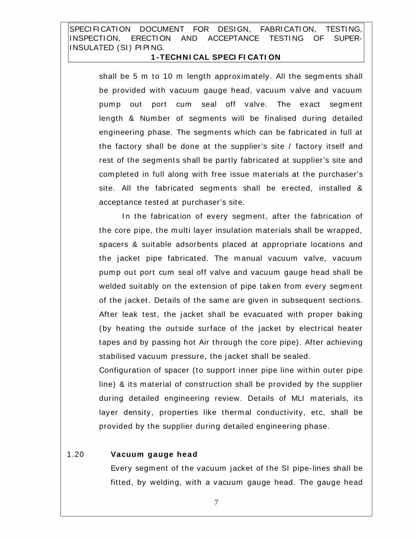
shall be 5 m to 10 m length approximately. All the segments shall
be provided with vacuum gauge head, vacuum valve and vacuum
pump out port cum seal off valve. The exact segment
length & Number of segments will be finalised during detailed
engineering phase. The segments which can be fabricated in full at
the factory shall be done at the supplier’s site / factory itself and
rest of the segments shall be partly fabricated at supplier’s site and
completed in full along with free issue materials at the purchaser’s
site. All the fabricated segments shall be erected, installed &
acceptance tested at purchaser’s site.
In the fabrication of every segment, after the fabrication of
the core pipe, the multi layer insulation materials shall be wrapped,
spacers & suitable adsorbents placed at appropriate locations and
the jacket pipe fabricated. The manual vacuum valve, vacuum
pump out port cum seal off valve and vacuum gauge head shall be
welded suitably on the extension of pipe taken from every segment
of the jacket. Details of the same are given in subsequent sections.
After leak test, the jacket shall be evacuated with proper baking
(by heating the outside surface of the jacket by electrical heater
tapes and by passing hot Air through the core pipe). After achieving
stabilised vacuum pressure, the jacket shall be sealed.
Configuration of spacer (to support inner pipe line within outer pipe
line) & its material of construction shall be provided by the supplier
during detailed engineering review. Details of MLI materials, its
layer density, properties like thermal conductivity, etc, shall be
provided by the supplier during detailed engineering phase.
Vacuum gauge head
Every segment of the vacuum jacket of the SI pipe-lines shall be
fitted, by welding, with a vacuum gauge head. The gauge head
SPECIFICATION DOCUMENT FOR DESIGN, FABRICATION, TESTING, INSPECTION, ERECTION AND ACCEPTANCE TESTING OF SUPER-INSULATED (SI) PIPING.
1-TECHNICAL SPECIFICATION
8
1.21
1.22
shall be of recent (2016) make of PIRANI type of Edwards/
Alcatel/ Pfeiffer make with a measurement range of 5 mbar to
10-3 mbar and an accuracy of ± 20 % of the displayed value.
Approval of the make, model & specification of vacuum gauge
head shall be obtained from the purchaser during detailed
engineering phase.
Vacuum pump out port cum seal off valves & tools
Every segment of the vacuum jacket of the SI pipe-lines shall be
fitted, by welding, a vacuum pump out port cum seal off valve
for pressure relief with
Helium leak tightness: [ 1 x 10⁻⁸ mbar l s- 1.
Material of construction: Austenitic Stainless Steel
Relief pressure: As per section 1.11
Vacuum level: As per section 1.14
Temperature: 5°C to 100 ºC
Specifications & detailed drawing of Vacuum pump out port
cum seal off valve indicating its make/manufacturer shall be
provided to the purchaser for approval during detailed
engineering phase. The pump out ports used on all the piping
segments shall be of the same dimension.
The supplier shall provide 2 Nos. of Vacuum pump out tools
common to mate with all the pump-out ports of the piping. The
other end of the pump-out tool shall be ISO KF end. The size of
the KF end shall be DN 16 KF, suitable for portable vacuum
pump for evacuating the S.I. pipeline vacuum jacket.
Vacuum controller :
Vacuum pressure controller cum display unit shall be provided
common for all vacuum gauge heads, preferably battery-
operated. In case if it is not feasible, the power supply to the
controller shall be 230 V ± 5%, 50 Hz ± 2%, single phase, AC.

SPECIFICATION DOCUMENT FOR DESIGN, FABRICATION, TESTING, INSPECTION, ERECTION AND ACCEPTANCE TESTING OF SUPER-INSULATED (SI) PIPING.
1-TECHNICAL SPECIFICATION
9
Approval of the make, model and its specification shall be
obtained from the Purchaser during detailed engineering phase.
1.23
1.23.1
Testing
The following are the tests to be performed. Details & scope of
inspection is covered in section 1.25. A detailed Quality control plan
shall be prepared by the supplier and submitted for review &
approval by purchaser during detailed engineering phase.
Tests to be carried out for raw materials & bought out
components required for fabrication at both supplier’s site &
purchaser’s site
a. Visual examination: All the pipes (inner & outer), pipe fittings,
bellows, etc, shall be visually examined for workmen-like finish.
b. Dimensional check: All the pipes (inner & outer), pipe fittings,
bellows, etc, shall be subjected to dimensional check.
c. Chemical analysis: One specimen from each lot of pipes (inner
& outer) & pipe fittings, etc, shall be subjected to Chemical analysis
as per ASTM A 751.
d. Material test
Material test certificates for the physical and chemical properties of
all the materials such as pipes (inner & outer), bellows, pipe
fittings, vacuum valve, vacuum pump out port cum seal off valve of
outer jacket, etc, and other pressure bearing parts shall be
provided.
e. Ultra-sonic test: The outer pipe shall be subject to Ultra-sonic
test (100 %) by pulse echo or contact probe method as per ASTM E
213.
f. Eddy current test: The inner pipe shall be subjected to Eddy

SPECIFICATION DOCUMENT FOR DESIGN, FABRICATION, TESTING, INSPECTION, ERECTION AND ACCEPTANCE TESTING OF SUPER-INSULATED (SI) PIPING.
1-TECHNICAL SPECIFICATION
10
current test as per ASTM E 426.
g. Flattening test: Pieces of pipes (inner & outer) of length
63.5mm (2.5”) cut from the ends of 5% of pipe lengths per lot shall
be subject to flattening test to prove ductility & soundness.
h. Intergranular corrosion test: One specimen from each lot of
pipes (inner & outer) & pipe fittings shall be subjected to
Intergranular corrosion test.
i. Pressure test: All the pipes (inner & outer) shall be
hydraulically pressure-tested with Water as per ASTM A 530.
j. Cleanliness: All the pipes shall be pickled, passivated and
dried. The ends of pipes which are to be used for fabrication at
purchaser’s site shall be blanked off by dust-tight plastic caps
before transportation to purchaser’s site.
k. Pressure test for bellows
All the bellows shall be subjected to pneumatic pressure test
with dry air or gaseous Nitrogen at 5 bar (1.25 times MAWP of
the outer jacket pipeline).
l. MSLD leakage test for bellows: The global leakage rate
across bellows shall be measured with gaseous Helium Mass
Spectrometer Leakage Detector (MSLD) to establish the
permissible leakage rate values finer than specified in section
1.13 by hood technique as per Article 10, Section V, ASME. The
leakage test shall be performed by shrouding the entire outside
surface of the bellows assembly with a plastic bag to hold
gaseous Helium + gaseous Air mixture at a positive pressure
and by evacuating and connecting the inlet/ outlet port to
MSLD. Leakage test by detector probe or tracer probe technique
is not acceptable.

SPECIFICATION DOCUMENT FOR DESIGN, FABRICATION, TESTING, INSPECTION, ERECTION AND ACCEPTANCE TESTING OF SUPER-INSULATED (SI) PIPING.
1-TECHNICAL SPECIFICATION
11
m. Welding joint test for bellows (wherever applicable):
All butt welding joints in the bellows shall be subjected to
radiographic test with X-rays or gamma rays to 2-2T sensitivity
as per Section IX, ASME. All the socket welding joints shall be
subjected to dye-penetrant test.
n. Bellows cyclic life test:
One per batch of bellows of same size & type used in the SI
pipelines shall be subjected to cyclic life test as per BS 5352
standard (minimum 5000 cycles).
o. Cleanliness:
All the interior flow surfaces of the bellows assembly shall
be degreased and cleaned to Oxygen service standards.
p. All vacuum gauges shall be calibrated.
q. Relief pressure test for vacuum pump out port cum seal
off valve: One per lot of the same shall be relief pressure
tested as per relevant standards.
Manufacturer’s test certificates for all the above tests
approved by TPI shall be submitted to purchaser for
review before despatch.
1.23.2 Tests to be carried out for all the S.I pipe line segments
fabricated at supplier’s site
a. Weld joint tests
1. For Inner(core) pipe
All the socket weld joints shall be subjected to DP test at the root
weld as well as at the final weld.
All the butt weld joints shall be subjected to DP test at the root
weld run and 100% radio-graphic test with X-rays to 2 – 2T

SPECIFICATION DOCUMENT FOR DESIGN, FABRICATION, TESTING, INSPECTION, ERECTION AND ACCEPTANCE TESTING OF SUPER-INSULATED (SI) PIPING.
1-TECHNICAL SPECIFICATION
12
sensitivity at the final weld. All the x-ray films shall be handed over
to the purchaser.
2. For outer (jacket) pipe:
All the socket weld joints shall be subjected to DP test at the root
weld as well as at the final weld.
All the butt weld joints shall be subjected to DP test at the root
weld run and 10% radio-graphic test (wherever possible) with X-
rays to 2 – 2T sensitivity at the final weld.
3. For the radiographic tests on the piping segments at supplier’s
works, purchaser reserves the right to have full access to examine
and verify the X-ray films. All the x-ray films shall be handed over
to the purchaser.
b. Pressure test
All the piping segments fabricated at suppliers’ site shall be
subjected to pneumatic pressure test at 1.1 times the MAWP using
gaseous nitrogen (GN2).
c. Leak test (at ambient temperature)
The leak tightness, of all the segments fabricated at supplier’s site
of SI pipelines, across the inner pipe as well as the outer jacket
shall be tested with Gaseous Helium Mass Spectrometer Leak
Detector (MSLD) by hood technique. The measured leak rate
shall be finer than given in Para no. 1.13. While leak-testing
the inner pipes, the internal volume shall be charged to its MAWP
with a mixture of 75 % GN2 + 25 % Gaseous Helium and the
annular volume between the inner vessel and the outer vessel be
evacuated and connected to MSLD. While leak-testing the outer
jackets, the exterior surface of the outer vessel shall be shrouded

SPECIFICATION DOCUMENT FOR DESIGN, FABRICATION, TESTING, INSPECTION, ERECTION AND ACCEPTANCE TESTING OF SUPER-INSULATED (SI) PIPING.
1-TECHNICAL SPECIFICATION
13
by synthetic bag and charged to 1.5bar,(a) with a mixture of 75 %
Gaseous Nitrogen + 25 % Gaseous Helium and the annular volume
between the inner vessel and the outer vessel shall be evacuated
and connected to MSLD. Leakage test by detector probe or tracer
probe technique is not acceptable.
d. Vacuum stabilisation test
After evacuation of the jackets of each segment of SI pipe-lines,
the stabilised vacuum pressure shall be periodically recorded over 1
week period. Stabilised vacuum pressure in the jacket should not
1.23.3
exceed 1x 10⁻² m bar (at atmospheric temperature). Also the
permissible rise in vacuum pressure shall not exceed the value
predicted by the specified permissible leak rate.
e. Cold shock test:
The pipe segments fabricated at supplier’s site in full shall be
subjected to cold shock test by passing Liquid Nitrogen at 1 bar (g)
pressure through the inner pipe to check the soundness of
insulation and heat in leak rate may be established. At Purchasers
discretion, this test may be carried out during pre shipment review.
f. Cleaning of all the piping segments shall be carried out as per
Section 1.24.
Test certificates for all the tests mentioned above approved
by TPI shall be provided to purchaser for review.
Tests to be carried out for all the fabricated segments & SI
pipeline assembly at purchaser’s site

SPECIFICATION DOCUMENT FOR DESIGN, FABRICATION, TESTING, INSPECTION, ERECTION AND ACCEPTANCE TESTING OF SUPER-INSULATED (SI) PIPING.
1-TECHNICAL SPECIFICATION
14
a. Weld joint tests
As per Para No.1.23.2 a.
b. Pressure test
All the piping segments & SI pipeline assembly fabricated at
purchaser’s site shall be subjected to pneumatic pressure test at
1.1 times the MAWP using gaseous nitrogen (GN2)/ GHe by the
Supplier. Pneumatic pump/ booster pump required for the
pneumatic pressure test at Purchaser’s site to be arranged by the
supplier.
c. Leak test (at ambient temperature)
As per Para No.1.23.2 c.
The leak tightness, of all the segments & SI pipeline assembly
fabricated at purchaser’s site, across the inner pipe as well as the
outer jacket shall be tested with Gaseous Helium Mass
Spectrometer Leak Detector (MSLD) by hood technique. Both the
measured leak rate for individual segments & for pipeline
assembly shall be finer than given in Para no. 1.13.
Supplier shall bring their own MSLD for tests at purchaser’s site.
Purchaser will provide gaseous Nitrogen and gaseous Helium only,
if required for leak tests at Purchaser’s site on free of cost.
d. Vacuum stabilisation test
As per Para No.1.23.2 d.
e. Cleaning of all the piping segments shall be carried out as per
Section 1.24.
Test certificates for all the tests mentioned above approved
by Quality Control (QC) team of purchaser shall be provided
to purchaser for review.
SPECIFICATION DOCUMENT FOR DESIGN, FABRICATION, TESTING, INSPECTION, ERECTION AND ACCEPTANCE TESTING OF SUPER-INSULATED (SI) PIPING.
1-TECHNICAL SPECIFICATION
15
1.23.4 Acceptance Tests to be carried out for SI pipelines at
purchaser’s site
LN2/GN2/GHe required for acceptance tests will be supplied by
purchaser
a) Pressure test at cryogenic temperature
All the SI piping assembly shall be subjected to pressure test with
Liquid Nitrogen / Cold GHe/ GN2/ GHe at its MAWP.
b)Global Leak test (at ambient temperature) after Pressure
test at cryogenic temperature As per Para No.1.23.2 c.
The leak tightness, of all the SI pipeline assemblies fabricated, across
the inner pipe as well as the outer jacket shall be tested with
Gaseous Helium Mass Spectrometer Leak Detector (MSLD) by hood
technique. The measured leak rate shall be finer than given in
Para no. 1.13.
c. Vacuum level test
Vacuum level in all individual pipeline segments shall be measured
before & after pressure test at cryogenic temperature for 1 week and
tabulated.
D. Performance test with actual fluids:
i. Chilling & filling of the SI pipelines with the respective working
fluids, conducting flow test at nominal flow rates and working
pressure to verify conformance with thermal, structural and
functional specification.
ii. To validate heat in leak rate specification.
iii. To verify performance of all instruments with respect to the
specification
SPECIFICATION DOCUMENT FOR DESIGN, FABRICATION, TESTING, INSPECTION, ERECTION AND ACCEPTANCE TESTING OF SUPER-INSULATED (SI) PIPING.
1-TECHNICAL SPECIFICATION
16
The surface temperature measured on the outside surface of the jacket pipe
will be restricted to 5 K below the atmospheric temperature.
Detailed procedure for performance test shall be prepared by the supplier &
provided to purchaser for approval. Supplier shall follow strictly the approved
procedure during performance test.
1.24 CLEANING
All the interior & exterior surface of the fabricated piping segments of
SI pipe-lines & erected pipeline assembly shall be cleaned as per the
following procedure:
a. Mechanical cleaning: All the metallic surfaces with scales and
newly welded surfaces shall be cleaned by scrubbing with SS wire
brush. The loose particles generated by mechanical cleaning shall
be removed by blowing with compressed air.
b. De-greasing: The oil and grease adherent to the surface shall be removed by vapour phase de-greasing with Tri Chloro Ethylene (TCE) or Per Chloro Ethylene (PCE), followed by liquid phase de- greasing with TCE or PCE. All the interior flow surfaces of the pipes shall be degreased and cleaned to Oxygen service standards.
c. Preservation: The volume inside the pipe-lines shall be thoroughly purged & dried with GN2 or dry Air to reduce the moisture content to ≤ 20 ppm. The ends of the pipe-lines shall be blanked off during transportation and storage. The pipe-lines shall be kept pressurised with GN2 or dry Air at ~ 3 bar (a) during transportation and storage.
1.25 INSPECTION
1.25.1 Inspection at supplier’s site:
Inspection of all the raw materials, bought-out materials required for fabrication at both supplier’s site & purchaser’s site, fabrication work at supplier’s site, tests & cleanliness performed at supplier’s works

SPECIFICATION DOCUMENT FOR DESIGN, FABRICATION, TESTING, INSPECTION, ERECTION AND ACCEPTANCE TESTING OF SUPER-INSULATED (SI) PIPING.
1-TECHNICAL SPECIFICATION
17
shall be performed and certified by a reputed third party inspection agency (TPI). TPI agency shall be chosen from the following list only:
a. Lloyds Register Industrial Services Pvt Ltd (LRIS) b. Bureau Veritas Industrial Services Pvt Ltd (BVIS) c. Det Norske Veritas (DNV) d. Technischer Uberwachungs Verein (TUV) e. Bax Counsel Inspection Bureau Pvt Ltd
It shall be the responsibility of the supplier to arrange for and coordinate with the TPI agency.
The broad scope of inspection (TPI) shall be as follows.
a. Identification of all the materials such as gauge head, pipes, pipe fittings, bellows, etc, and review of the test and calibration certificates for compliance with the Purchasers specification.
b. Witnessing of welding procedure qualification and welder’s performance qualification tests. If the welders already possess the performance certificate, the TPI agency shall review WPS, PQR & WPQ and authorise the same.
c. Review of all X-ray films of radio-graphic tests for possible defects in the weld joints.
d. Inspection at any stage of fabrication to ensure that the methodology employed for fabrication is in compliance with the requirements of standards/ codes, practices, purchase order specification and the approved documents.
e. Witnessing of DP tests, pressure test, leak test (inner & outer lines), vacuum stabilisation test, cleanliness & other tests carried out by the supplier.
f. Witnessing of weld joint set up at random.
g. Witnessing of cold shock test on S.I. pipe segments to a procedure and acceptance standard agreed by the purchaser. Heat-in leak rate may be established during the test.
h. Verification of cleaning for oxygen service for the pipeline to a procedure accepted by the purchaser.
SPECIFICATION DOCUMENT FOR DESIGN, FABRICATION, TESTING, INSPECTION, ERECTION AND ACCEPTANCE TESTING OF SUPER-INSULATED (SI) PIPING.
1-TECHNICAL SPECIFICATION
18
Inspection report and final release note for all raw materials, bought out components, etc and fabricated segments of SI pipelines shall be issued by the TPI agency.
The lump sum charges for inspection by the TPI agency shall be separately mentioned in the quotation. However, the payment of inspection charges shall be made only upon production of invoice by the TPI agency without exceeding the lump sum amount. Apart from inspection by the TPI agency, the Purchaser‘s representative(s) shall inspect the system at any stage of fabrication. Upon completion of fabrication, the supplier shall organise Pre-Shipment Review (PSR) meeting at their office/ factory, in which the supplier, the purchaser’s representative(s) and the TPI agency shall participate. Upon satisfactory review of the test certificates and inspection reports of fabrication, the purchaser will accord the shipment clearance.
1.25.2 Inspection at purchaser’s site:
Inspection of all fabrication work, erection, all the tests & cleanliness performed at purchaser’s site shall be performed and certified by a QC team of purchaser.
The broad scope of inspection shall be as follows.
a. Identification of the materials such as equipments, flow components, instruments, gauge head, pipes, pipe fittings, bellows etc and review of the test and calibration certificates for compliance with the purchasers specification.
b. Witnessing of welding procedure qualification and welder’s performance qualification tests. If the welders already possess the performance certificate, QC team of purchaser shall review and authorise the same.
c. Review of all X-ray films of radio-graphic tests for possible defects in the weld joints.
d. Inspection at any stage of fabrication to ensure that the methodology employed for fabrication is in compliance with the

SPECIFICATION DOCUMENT FOR DESIGN, FABRICATION, TESTING, INSPECTION, ERECTION AND ACCEPTANCE TESTING OF SUPER-INSULATED (SI) PIPING.
1-TECHNICAL SPECIFICATION
19
requirements of standards/ codes, practices, purchase order specification and the approved documents.
e. Witnessing of DP tests, pressure test, leak test, vacuum stabilisation test, cleanliness, final acceptance test & other tests carried out by the supplier.
f. Participating with inspection reports of all the above activities in the final acceptance review & handing over of SI pipelines by the supplier.

SPECIFICATION DOCUMENT FOR DESIGN, FABRICATION, TESTING, INSPECTION, ERECTION AND ACCEPTANCE TESTING OF SUPER-
INSULATED (SI) PIPING. 2. SPECIFICATION OF INSTRUMENTATION
20
2.1 Temperature sensors:
2.1 a) Fluid temperature sensor/probe (3 Nos., Tag No: STI 601A, 601B & 601C) shall be issued to the supplier as Free Issue Material (FIM) by IPRC against Bank Guarantee (BG).
2.1 b) Surface temperature sensor (2 Nos., Tag No: STC 601A & 601B) shall also be given as FIM by IPRC against BG.
2.1 c) The surface temperature sensor bonding procedure and the adhesives for bonding shall be provided during Design and detailed Engineering phase, (clause 3.1 under section 3.0 Scope of work in the specification document).
2.1 d) Fluid temperature probe interface details & drawings also will be provided during Design and detailed Engineering phase, (clause 3.1 under section 3.0 Scope of work in the specification document).
2.2 Vacuum feed through for temperature sensor:
2.2 a) Supply and realization of required number of vacuum feed through (with 16 pin configuration) in the S.I pipeline for the above Fluid temperature sensors and Surface temperature sensors is under the supplier’s scope.
2.2 b) Mounting of temperature sensor, wiring and termination to the Vacuum feed through is under the scope of the Supplier.
2.2 c) Mating portion for the vacuum feed through connector (Ambient air side), pins and crimping tools to be provided by the Supplier to IPRC.
2.3 Pressure transmitters:
Pressure transmitters - 2 Nos., isolation manifold valves – 2 Nos.,
canalization tube (Approximately - 4 m long) & fittings for pressure
transmitter will be supplied by Purchaser at Purchaser’s site.
Mounting of pressure transmitters with isolation manifold valves
and canalization tubing connections in the S.I. piping interface
– 1/2” NPT (M) shall be done by the Supplier at Purchaser’s site. The
location of the pressure transmitters shall be as given in the piping

SPECIFICATION DOCUMENT FOR DESIGN, FABRICATION, TESTING, INSPECTION, ERECTION AND ACCEPTANCE TESTING OF SUPER-
INSULATED (SI) PIPING. 2. SPECIFICATION OF INSTRUMENTATION
21
layout drawing. Pressure transmitters shall be properly supported by
the supplier.
Specification of 16-Pin vacuum feed through connector Make : Insulator seal INC, USA/ Deutch, France / Douglas, USA or
equivalent Application : Instrumentation, Low power
Leak Tightness : <1×10E-8 torr Type : UHV, MIL-C-5015 Grade Voltage : 700 VDC
Contact amps : 10A/Contact AWG of contacts : 18/20/22 No. of contacts : 16-Pins
1. Connector (Air side plug) § Material
Body : SS 304
§ Temperature range : 0 to +125˚C § Contact air side : Solder cup contacts § Insulator : Alumina ceramic
2. Socket
§ Type : MIL-C-5015 Grade § Voltage : 700 VDC § No. of contacts : 8-Pins § Material
v Body : SS 304 v Contacts : Alumel

SPECIFICATION DOCUMENT FOR DESIGN, FABRICATION, TESTING, INSPECTION, ERECTION AND ACCEPTANCE TESTING OF SUPER-
INSULATED (SI) PIPING. 2. SPECIFICATION OF INSTRUMENTATION
22
§ Installation : NW 35 CF § Temperature range : -40 to +125˚C § Contact vacuum side: Gold plated crimp contact with Ceramic spacer
Note: Approval for specification & make of the Vacuum feed through connectors shall be obtained from purchaser during detailed engineering review (DER).
SPECIFICATION DOCUMENT FOR DESIGN, FABRICATION, TESTING, INSPECTION, ERECTION AND ACCEPTANCE TESTING OF
SUPER-INSULATED (SI) PIPING.
23
3. SCOPE OF WORK
3.0 General:
The overall scope of work in brief, includes the following. However the details of each work are dealt in detail in respective sections
� Design & detailed engineering of Super Insulated (SI) pipelines as per the technical specifications & preliminary
Isometric piping layout drawing (No: SST/CTC/SI/L1) enclosed.
� Preparation of design documents, detailed assembly & fabrication drawings etc. as per the list of documents
indicated in Section 3.1 & submitting the same for review & approval by purchaser.
� Purchase of all raw materials & bought out components required for SI pipelines except free issue materials.
Fabrication, testing & inspection of segments of SI pipelines
at supplier’s site (factory) as per sections 1 & 2.
� Transportation of the factory fabricated segments to
purchaser’s site & storage at purchaser’s site.
� Fabrication of rest of the segments / additional segments of
SI pipelines as finalized during detailed engg review at the purchaser’s work site.
� Erection of all segments as per the isometric piping layout drawings prepared by the supplier and approved by the
purchaser.
� Final testing & handing over of Super Insulated pipelines at
purchaser’s site.
The overall scope of work is divided into 4 phases as follows:
� Phase 1: Design & Detailed engineering
� Phase 2: Fabrication at Supplier’s site & Delivery
� Phase 3: Fabrication at Purchaser’s site & Erection
� Phase 4: Final acceptance testing
The maximum period for execution of each phase of work is given
in the following sections. Delay in execution of any phase should
not be carried over to next phase.

SPECIFICATION DOCUMENT FOR DESIGN, FABRICATION, TESTING, INSPECTION, ERECTION AND ACCEPTANCE TESTING OF
SUPER-INSULATED (SI) PIPING.
24
3.1. DESIGN & DETAILED ENGINEERING
Immediately upon receipt of purchase order, supplier shall carry
out detailed design of the Super Insulated Pipelines as per the
technical specifications, prepare following documents & submit the
same (2 copies) to purchaser for review.
a. Pipe-line isometrics: The 3-dimensional isometric drawings of the SI pipe-lines shall be made. The drawings shall be fully
dimensioned and the locations of fittings, bellows compensators,
instruments, pipe supports, etc shall be shown. Each isometric drawing shall contain the detailed Bill Of Materials (BOM). The
drawings shall be made on appropriate software (CADpipe, AutoPlant or any CAD-based software) and provided in Compact
Discs (CDs), along with hard copy.
b. Detailed cross sectional/ fabrication drawing of each segment of SI pipeline, indicating the dimensions and Material Of
Construction (MOC) of each part.
c. General Arrangement (GA) drawing, indicating the overall dimensions of the product along with the accessories.
d. Structural & thermal design of each segment of SI pipelines. e. Heat in leak rate calculations for each segments
f. Design of joints g. Cable lay-out h. Detailed QAP for all the works carried out at both supplier’s &
purchaser’s site.
i. Procedure and acceptance criteria for fabrication, erection and final acceptance testing
j. Civil and electrical requirements
k. List of sub-vendors/ sub-contractors for each items
l. Calculations for sizing and positioning of U- bends in the inner pipe for thermal compensations, outer bellows jacketing the U-
bends as outer wall. Design calculations with details such as Deflection, Axial spring rate, Lateral spring rate, Torsional
spring rate, Limiting internal design pressure based on column instability, Limiting design pressure based on in plane
instability, Bellows effective area, stresses etc (based on EJMA / relevant standards) for each bellows shall be submitted to the
purchaser for approval.

SPECIFICATION DOCUMENT FOR DESIGN, FABRICATION, TESTING, INSPECTION, ERECTION AND ACCEPTANCE TESTING OF
SUPER-INSULATED (SI) PIPING.
25
m. Design & drawing of supports of both outer pipeline and inner pipeline. Configuration details of spacer & its material of
construction shall be provided n. Purchase specification of all the raw materials, & bought out
components etc & its manufacturers/vendors. o. Details of MLI materials, its layer density, apparent thermal
conductivity etc p. Resume of work of all key personnel, their qualification and
experience over the past 10 years and the number of workers by trade, which they propose to employ during execution of
work at purchaser’s site. q. The 3D drawings of overall layout of all piping assemblies shall
be made on appropriate 3D CAD software and provided in
Compact Discs (CDs) along with hard copy. r. Detailed proposal for temperature control near weld joints as
mentioned in section 1.17 s. Structural Support details of the SI pipelines with drawings.
t. Details of PCC/RCC for pipe supports. u. Fabrication drawings of adaptors for temperature probes.
Within 8 weeks from the date of placement of purchase
order, the above mentioned documents shall be submitted by the
supplier for review by the purchaser.
During detailed engineering review, if required, the supplier
shall participate in the review at IPRC, Mahendragiri. During
detailed engineering review, change, if any in the scope of site
work at purchaser’s site shall be identified & approval shall be
obtained from purchaser.
The documented procedure for bonding surface
temperature sensors - 2 Nos. (Free Issue Material, FIM) and
mounting adaptor interface drawing for fluid temperature
probes - 3 Nos. (FIM) will be provided to the supplier by the
Purchaser during detailed engineering.
Two sets of revised detailed engineering documents after
incorporating changes/ modifications required during detail
engineering review shall be submitted to the purchaser

SPECIFICATION DOCUMENT FOR DESIGN, FABRICATION, TESTING, INSPECTION, ERECTION AND ACCEPTANCE TESTING OF
SUPER-INSULATED (SI) PIPING.
26
immediately after review but not later than 2 weeks from the date
of review for purchaser’s final approval.
However Purchaser’s approval does not absolve the supplier
from their responsibility to comply with P.O.
3.2. FABRICATION AT SUPPLIERS’S SITE AND DELIVERY
This phase shall commence upon approval and acceptance of the
detailed engineering documents by the purchaser. This phase
involves
1. Purchase of raw materials & bought out components such as
pipes, pipe fittings, bellows, manual vacuum valve, vacuum
pump out port cum seal off valve, vacuum gauge head, etc,
needed for both fabrication at supplier’s site & fabrication at
purchaser’s site based on the specification cleared by the
purchaser.
2. Fabrication of segments of SI lines at supplier’s site.
3. Testing, cleaning, jacket evacuation of segments fabricated at
supplier’s site as per Section 1. Line number shall be clearly
marked on each segment suitably.
4. The in-process (stage) and pre-shipment (final) inspection of
the system during fabrication shall be carried out by the TPI
agency. Apart from inspection by TPI agency, the purchaser’s representative(s) may also carry out inspection at any stage at
their own discretion. After completion of fabrication at supplier’s site, but, prior to packing of the consignment for
transportation, the supplier shall organise a Pre-Shipment Review (PSR) at their office/ factory, in which the supplier, the
purchaser’s representative(s) and the TPI agency shall participate. All the test certicates as per Section 1.23, duly
approved by the TPI agency, shall be submitted to the Purchaser during review.
5. Upon approval by the purchaser, the supplier shall pack and
transport the consignments to the purchaser’s site and un-load them at the purchaser’s site. The consignments shall be
insured by the supplier. The supplier shall undertake full
SPECIFICATION DOCUMENT FOR DESIGN, FABRICATION, TESTING, INSPECTION, ERECTION AND ACCEPTANCE TESTING OF
SUPER-INSULATED (SI) PIPING.
27
responsibility of handling, transportation, insurance, clearance and storage. Material handling equipment required for
unloading of SI segments at purchaser’s site may be provided by purchaser subject to availability on chargeable basis.
However, supplier is responsible for safe unloading of all the items at site.
The lists of documents (2 copies) to be provided by the supplier during this phase are as follows:
a. Pipe-line isometrics: The 3-dimensional isometric of the
SI pipe-line segments (as built) fabricated at the supplier’s site shall be made. The drawings shall be fully dimensioned and
the locations of fittings, bellows compensators, flow components, instruments, pipe supports, etc shall be shown.
Each isometric drawing shall contain the detailed Bill Of Materials (BOM). The drawings shall be made on appropriate
software (CAD pipe, Auto Plant or any CAD-based software) and provided in Compact Discs (CDs) along with hard copy.
b. Detailed cross sectional/ fabrication drawing of each segment
of SI pipelines (as built) fabricated at supplier’s site, indicating
the dimensions and Material Of Construction (MOC) of each part.
c. A General Arrangement (GA) drawing (as built), indicating the
overall dimensions of the SI pipelines along with the accessories.
d. Test/calibration certificates and inspection reports of all the raw
materials such as pipes, pipe fittings, bellows, instruments etc
& factory fabricated segments (including the radio-graphic
films) as per QAP.
e. Wiring diagram of instrumentation and electrical systems
f. Procedure for carrying out performance test.
g. Estimation of quantity of fluids to be supplied by the purchaser
during erection and final acceptance tests.
h. Instruction manual for installation, operation, maintenance and trouble-shooting of S.I pipelines.

SPECIFICATION DOCUMENT FOR DESIGN, FABRICATION, TESTING, INSPECTION, ERECTION AND ACCEPTANCE TESTING OF
SUPER-INSULATED (SI) PIPING.
28
Within 6 months from the date of purchase order, all the above mentioned works in section 3.1 & 3.2 (Phase 1 & 2) shall be
completed.
3.3. FABRICATION AT PURCHASER’S SITE & ERECTION
This phase shall commence upon un-loading of the consignments
at the purchaser’s site. This phase involves
1. All Works identified under this heading during detailed engg
review like (a). Fabrication of segments of SI lines as per
section 1 and if any identified during detailed engineering
review. Line number shall be clearly marked on the outer
jackets (b). Testing of segments of SI lines fabricated at
purchaser’s site as per Section 1.23.
2. Erection, installation of all the fabricated segments with proper
supports etc. at the purchaser’s site as per the approved
drawings & documents. Providing PCC/RCC required for pipe
supports as per details provided by supplier along with
excavation of existing PCC floor.
3. Testing, cleaning, jacket evacuation of total system at
purchaser’s site.
4. The in-process (stage) inspection during this phase shall be
carried out by the purchaser’s QC team
At the end of erection, the following documents (2 copies) shall be
submitted:
a. The 3D drawings of overall layout (as built) of all piping
assemblies shall be made on appropriate 3D software and provided in Compact Discs (CDs), along with hard copy
b. Pipe-line isometrics: The 3-dimensional isometric drawings of
the SI pipe-lines (as built) shall be made. The drawings shall be fully dimensioned and the locations of fittings, bellows
compensators, flow components, instruments, pipe supports, etc shall be shown. Each isometric drawing shall contain the
detailed Bill Of Materials (BOM). The drawings shall be made on appropriate software (CADpipe, AutoPlant or any CAD-based

SPECIFICATION DOCUMENT FOR DESIGN, FABRICATION, TESTING, INSPECTION, ERECTION AND ACCEPTANCE TESTING OF
SUPER-INSULATED (SI) PIPING.
29
software) and provided in Compact Discs (CDs), along with hard copy
c. As-built cable lay-out drawing
d. Certificates of all the tests (including radio-graphic films)
done during erection.
e. Inspection report by the purchaser.
Within 7 months from the date of purchase order, all the above
mentioned works in section 3.1 , 3.2 & 3.3 (Phase 1 , 2 & 3) shall be completed.
3.4. FINAL ACCEPTANCE TEST & HANDING OVER.
This phase shall commence upon completion of erection. The
performance of the system is to be validated during this phase in
compliance with the specifications of purchase order.
This phase involves
� Testing of SI pipe lines assembly as per Section 1.23
� After satisfactory testing, painting shall be done as per
Section 3.7.
A final acceptance review will take place after all the necessary
final acceptance tests are completed and are documented as per
the purchaser’s requirements.
At the end of final acceptance tests, the following documents (2
copies) shall be submitted:
a. Certificates of all the tests done during final acceptance.
b. Inspection report by the purchaser.
c. Final acceptance report (by the purchaser)
d. Detailed documents for
� Maintenance (routine, preventive and break-down) � Trouble-shooting
� Warranty/Guarantee certificate

SPECIFICATION DOCUMENT FOR DESIGN, FABRICATION, TESTING, INSPECTION, ERECTION AND ACCEPTANCE TESTING OF
SUPER-INSULATED (SI) PIPING.
30
Upon acceptance of the above by purchaser, all the S.I pipelines shall be handed over to the purchaser by the supplier.
Within 8 months from the date of purchase order, all the above mentioned works including handing over as per section
3.1 , 3.2 , 3.3 & 3.4 (Phase 1 , 2 , 3 & 4) shall be completed.
3.5 Supply of materials & Scope of supplier
Supply of all materials required for the S.I pipe line assembly except
those free issue materials given in Table-1 in drawing
No: SST/CTC/SI/L1 are under the scope of supplier. The supply of
materials includes the following in general
a. Pipes for core pipe, jacket pipe and branch pipe
b. Pipe fittings such as elbows, bends, tees, half couplings, full
couplings, reducers, threaded nipples and adaptors, flanges,
seals, bolts, nuts, washers, etc.,
c. Insulation materials such as multi layers of Aluminized or
silverised Mylar/ Aluminum foil with Glass fibre, spacers,
suspension, absorbents, etc.
d. Bellows to compensate for thermal contraction
e. Manual vacuum valve, vacuum pump out port cum seal off
valve, vacuum measuring gauge head for each S.I piping
segment.
f. Materials required for supports and clamps at requisite span
for the S.I pipe line.
g. Vacuum/ temperature feed through connectors.
h. Adaptors/Connectors required for connecting the free issue
materials to the S.I pipe segments.
i. Other materials, if any required for S.I piping assembly and
erection at purchaser’s site.
j. Temperature sensors will be supplied by the purchaser.
Whereas assembly of these temperature sensors with suitable
interfaces & vacuum feed through connectors, Mating
connector of feed through for further field wiring to junction
box / rack interface are in the scope of supplier.

SPECIFICATION DOCUMENT FOR DESIGN, FABRICATION, TESTING, INSPECTION, ERECTION AND ACCEPTANCE TESTING OF
SUPER-INSULATED (SI) PIPING.
31
k. Supply of Vacuum feed through connector (16 pins):
Mating connector of feed through to be supplied for further
field wiring to junction box / rack inter face.
l. Pipe supports: Pipe supports for SI pipelines at regular
intervals as required & as per approved drawings etc for the
same are under the scope of supplier. Grouting of the pipe
supports to the concrete pavement or welding of the pipe
support to the steel structure as required at work site are
under the scope of supplier. The piping shall be properly
clamped to the pipe supports. Civil works including excavation
of already laid PCC/RCC pavement and construction of new
pedestals are to be done by the supplier. However complete
details should be provided by supplier during DER. Pipe
supports shall be painted as per section 3.7.
m. All the interface connections between SI pipelines & free issue
materials are under the scope of supplier.
3.6 FREE ISSUE MATERIALS (FIM) FROM PURCHASER & SCOPE OF
PURCHASER/SUPPLIER
3.6.1 Supply of Free issue materials by purchaser are as
listed in drawing No: SST/CTC/SI/L1
a. Supply of Pneumatic actuated valves & Cryogenic filter
Pneumatic actuated valves, cryogenic filter, Fluid temperature sensors, Surface temperature sensors will be supplied as free issue
materials (As per Table-1 in drawing No: SST/CTC/SI/L1).
The integration of these free issue materials with SI pipe lines are to be carried out by the supplier.
Purchaser will furnish the drawings of free issue materials to
the supplier during detailed engineering. Fabrication drawings of all the adapters, interfaces, etc., required for integration of these free
issue materials with SI pipeline are to be prepared by supplier & shall
be submitted to purchaser for approval before starting fabrication.

SPECIFICATION DOCUMENT FOR DESIGN, FABRICATION, TESTING, INSPECTION, ERECTION AND ACCEPTANCE TESTING OF
SUPER-INSULATED (SI) PIPING.
32
b. Pressure transmitters
Pressure transmitters - 2 Nos. and Isolation valves- 2 Nos. will be
supplied by Purchaser at Purchaser’s site. Mounting of pressure
transmitters and tubing connections for transmitters shall be done
by the Supplier. The location of the pressure transmitter shall be
as given in the piping layout drawing. Pressure transmitters
shall be connected and supported by the supplier. The length of
tubing (tube - O.D. 12.7 mm) for the pressure transmitters is
approximately - 2 m.
c. Temperature sensors :
Temperature sensor will be supplied by the purchaser. Whereas
assembly of these temperature sensor with suitable interface &
vacuum feed through connector, Mating connector of feed through
for further field wiring to junction box / rack interface are in the
scope of supplier. Drawing of the interface adaptor shall be prepared
by the supplier and got it approved by the purchaser.
3.6.2 Supply of gaseous nitrogen by Purchaser for pneumatic pressure
testing and gaseous helium for MSLD testing of the piping
assembly after erection at purchaser’s site by Purchaser.
3.6.3 Supply of water and electricity (free of charge) for carrying out
the erection work at purchaser’s site.
3.6.4 GN2, LN2, GHe required for testing during erection and final
acceptance testing phase at purchaser’s site will be supplied free of
cost.
3.6.5 Supply of flow components (Free Issue Materials) as given in
drawing No. SST/CTC/SI/L1. The overall dimensions of these
components will be furnished by the purchaser to the supplier
during detailed engineering. All these flow components will be
issued by purchaser at purchaser’s site for site welding.

SPECIFICATION DOCUMENT FOR DESIGN, FABRICATION, TESTING, INSPECTION, ERECTION AND ACCEPTANCE TESTING OF
SUPER-INSULATED (SI) PIPING.
33
3.6.6 Cost break up for FIMs to be integrated with S.I. pipelines at
supplier’s site is given below. The FIMs will be issued to the
supplier so that they can take the FIMs out of IPRC.
___________________________________________________
Sl No. Free Issue Material Quantity Total Amount
___________________________________________________
1) Pneumatic actuated valves 2 Nos. Rs 4,66,000/-
2) cryogenic filter 1 No. Rs 11,45,000/-
3) Fluid temperature probes 3 Nos. Rs 1,35,000/-
4) Surface temperature sensors 2 Nos. Rs 15,000/-
5) Pressure transmitter with
isolation manifold valve 2 Nos. Rs 1,20,000/-
Supplier shall provide Bank Guarantee (BG) for the cost of FIMs
valid till handing over of S.I. pipelines at IPRC, Mahendragiri.
3.7 PAINTING
Finally, all the SI pipe-lines (over the jacket pipe) shall be painted
with maroon color identification bands of 100 mm width at 2 m
span. All the structural supports shall also be painted. Prior to
painting, the surfaces shall be suitably prepared. The painting
shall comprise 2 coats of primer (like red oxide) and 2 coats of
synthetic enamel. Line number shall be clearly marked on the
outer jackets.
3.8 SPARES
‘O’ rings & gaskets – 3 sets, Pirani gauges- 2 Nos., Vacuum feed
through connectors- 2 Nos. etc. shall be supplied as spares along
with S.I. pipelines at the time of handing over of the SI pipelines.
The above quantities of spares exclude the spares consumed if
any during installation and commissioning by the Supplier till
handing over.

SPECIFICATION DOCUMENT FOR DESIGN, FABRICATION, TESTING, INSPECTION, ERECTION, AND ACCEPTANCE TESTING
OF SUPER-INSULATED (SI) PIPING.
34
4: GENERAL TERMS & CONDITIONS OF SUPPLY 4.1 PRICES
Lump sum price may be quoted for the full scope of
S.I. piping work with breakup for Third Party Inspection (TPI) charges. Price shall be quoted as per the Price format enclosed as Annexure-A
4.2 PAYMENT TERMS 4.2.1. Milestone Payments
a. The Purchaser shall pay to the Supplier 30 % of the total price as advance, upon Detailed Engineering against bank guarantee. The payment shall be released after receipt by the Purchaser of invoice (commercially certified) from the Supplier. The following documents shall accompany the invoice while claiming this milestone payment:
i. Certification by the purchaser to the effect that Detailed Engineering is successfully completed.
ii. Bank guarantee for the sum of payment valid till arrival of the SI Pipelines at Mahendragiri
b. The Purchaser shall pay to the Supplier 40 % of the total price,
on receipt of the factory fabricated segments of SI Pipelines at Mahendragiri. The payment shall be released on receipt of the SI Pipelines and invoice (commercially certified) from the Supplier. The following documents shall accompany the invoice while claiming this milestone payment:
i. Certification by the Purchaser of having successfully completed the Pre-shipment review of fabricated segments of SI Pipeline after inspection and pre-shipment tests at the Supplier’s or their sub-contractor’s premises
ii. Inspection certificate & final release note by the Third party inspection agency for all raw materials, bought out components etc & fabricated segments of SI Pipeline.

SPECIFICATION DOCUMENT FOR DESIGN, FABRICATION, TESTING, INSPECTION, ERECTION, AND ACCEPTANCE TESTING
OF SUPER-INSULATED (SI) PIPING.
35
iii. Test certificates for all raw materials, bought out components etc & fabricated segments of SI Pipeline.
iv. Packing list (3 copies) showing dimensions, gross mass, net
mass and quantity & content of packages
c. The Purchaser shall pay to the Supplier 30 % of the total price, upon final acceptance test after successful completion of erection of S.I. pipeline & handing over by the supplier at Purchaser’s premises. The payment shall be released after final acceptance and receipt by the Purchaser of invoice (commercially certified) from the Supplier. The following documents shall accompany the invoice while claiming this milestone payment:
a. Purchaser’s certification of having successfully completed
final acceptance test of the SI Pipeline. b. Warranty certificate. c. Performance bank guarantee for 10 % of the total price
valid over the warranty period
4.3 COMPLETION PERIOD 4.3.1 The overall completion period reckoned from the date of
purchase order to the date of final acceptance test & handing over of the SI Pipelines at Mahendragiri shall be 8 months.
Handing over: Upon completion of final acceptance tests, the S.I pipe lines shall be handed over to the purchaser
4.3.2. Liquidated damages for delayed completion Except in case of Force majeure circumstances as detailed below, if the Supplier fails to deliver, erect, acceptance test & hand over the SI Pipelines within the period as specified in Section 4.3.1 above or any extension thereof as may be
SPECIFICATION DOCUMENT FOR DESIGN, FABRICATION, TESTING, INSPECTION, ERECTION, AND ACCEPTANCE TESTING
OF SUPER-INSULATED (SI) PIPING.
36
granted by the Purchaser, the Purchaser shall recover from the Supplier as liquidated damages a sum of one–half of one percent (0.5 %) of the total Order price for each calendar week or part thereof. The total liquidated damages shall not exceed 10 % of the Order price. The SI Pipelines shall be deemed to have been completed, only when all its component parts are also completed. If certain deliverables of the SI Pipeline are not completed in time, it will be considered that the completion is delayed until such time the missing deliverables are completed and accepted.
4.3.3 Extension of completion period under force majeure
circumstances
The term “Force majeure circumstances” shall mean inevitable accident, strike, lock-out, other conflicts of like nature, acts of public enemy, war, freight embargoes, breach of public order, lightning, fire, thunderstorm, flood, explosion, restrictions imposed by the Government and any other circumstance over which the Supplier has no control. If the completion of the S.I pipelines is delayed due to reasons of Force majeure circumstances, the Supplier shall, without delay, but within 30 days, notify to the Purchaser, in writing, of his claim for extension of time. The confirmation of the Force majeure circumstances shall be made by the purchaser. The Purchaser, on receipt of such notice, may agree to extend the order completion period as may be reasonable, but not more than 3 months. After the extended period of time, if the Supplier fails to resume execution of the order, the Purchaser reserves the right to cancel the order.
4.3.4 SUB – CONTRACTING
The supplier shall not assign or subcontract the work or any part of the work without the written approval of the purchaser. The responsibility of the performance of sub-

SPECIFICATION DOCUMENT FOR DESIGN, FABRICATION, TESTING, INSPECTION, ERECTION, AND ACCEPTANCE TESTING
OF SUPER-INSULATED (SI) PIPING.
37
contractor shall lie with the supplier. Any delay in carrying out the work by the subcontractor which affects the overall schedule of the work does not absolve the supplier from payment of compensation for the delays. All terms and conditions applicable to the supplier shall also be applicable to the sub-contractor.
4.3.5 CONFIDENTIALITY:
The technical information, drawings, specification, and other related documents forming part of enquiry or purchase order are the property of the purchaser and shall not be used for any other purpose except for the execution of the purchase order. The technical information, drawings, and other documents shall not be copied transcribed, traced or reproduced in any other form or otherwise in whole and / or duplicated, modified, divulged and / or disclosed to a third party and / or not misused in any other form whatsoever with out the purchaser’s consent in writing except to the extent required for the execution of the purchase order. These drawings, technical information, specifications and other related documents shall be returned to the purchaser with all approved copies and duplicates, if any immediately after they have been used for the agreed purpose.
4.4 DELIVERY 4.4.1 The Supplier shall arrange to deliver the SI Pipelines at
Mahendragiri. 4.4.2 The ultimate consignee shall be as follows:
Stores Officer, ISRO Propulsion Complex (IPRC), Department of Space, Government of India, Mahendragiri 627 133, Tirunelveli District, Tamil Nadu State, India.

SPECIFICATION DOCUMENT FOR DESIGN, FABRICATION, TESTING, INSPECTION, ERECTION, AND ACCEPTANCE TESTING
OF SUPER-INSULATED (SI) PIPING.
38
4.4.3. PACKING: The Supplier shall pack and crate SI pipeline in such a manner so as to protect them from damage and deterioration during the transportation. The Supplier shall be held responsible for all damages due to improper or inadequate packing.
4.5 SUPPLIER’S DEFAULT LIABILITY
The Purchaser may, upon 30 days written notice of default to
the Supplier, cancel the order in the circumstances detailed hereunder:
a If the Supplier fails to deliver the SI Pipeline within the delivery period specified in the Purchase order or within the period for which extension may be granted by the Purchaser to the Supplier. b If the Supplier commits breach of any terms and conditions of the Purchase order.
4.6 WARRANTY 4.6.1 The Supplier shall ensure and declare that the SI Pipeline
sold to the Purchaser as per this document are of the best quality and workmanship and in strict compliance with the technical specifications and shall also warrant that the SI Pipeline would continue to conform to the specification and quality during the warranty period specified below.
The Supplier shall warrant the SI pipelines against any faulty material or workmanship for a period of 12 months from the date of final acceptance & handing over at the Purchaser’s site.
4.6.2 Performance Bank Guarantee
The Supplier shall guarantee the successful and satisfactory performance/ operation of the SI pipeline under the

SPECIFICATION DOCUMENT FOR DESIGN, FABRICATION, TESTING, INSPECTION, ERECTION, AND ACCEPTANCE TESTING
OF SUPER-INSULATED (SI) PIPING.
39
conditions and for the services specified. As a performance security, the Supplier shall furnish a performance bank guarantee for 10 % of purchase order price to guarantee the faithful performance of the SI pipeline in accordance with all the specifications and terms specified herein valid for the warranty period as specified in Section 4.6.1 above. On due performance, the performance bank guarantee will be returned to the Supplier after expiry of the warranty period.
4.6.3 Rejection
In the event that the SI pipeline supplied by the Supplier is found defective in material or workmanship or otherwise not in conformity with the requirements of the technical specifications the Purchaser shall reject the same and notify to the Supplier, in writing, to rectify the same. The Supplier, on receipt of such notification shall assess the defect in consultation with the Purchaser and either rectify or replace the defective S.I pipelines free of cost to the Purchaser. If the Supplier fails to take corrective action within 30 days, the Purchaser shall, at his option recover the cost involved in such replacement or rectification from the Supplier
4.7 INDEMNITY
The Supplier shall warrant that all the materials supplied against purchase order are free and clean of infringement of any patent, copyright or trade mark, and shall at all times indemnify the Purchaser against all claims which may be made in respect of the S.I pipelines for infringement of any right protected by patent registration of design or trade mark and shall take all risk of accidents or damages which may cause a failure of the supply from whatever cause arising and the entire responsibility for the sufficiency of all the means used by him for the fulfillment of purchase order.

SPECIFICATION DOCUMENT FOR DESIGN, FABRICATION, TESTING, INSPECTION, ERECTION, AND ACCEPTANCE TESTING
OF SUPER-INSULATED (SI) PIPING.
40
4.8 PURCHASER–FURNISHED MATERIALS (“FREE ISSUE MATERIALS”)
The list of materials (flow components & instruments) to be furnished by the purchaser as Free-Issue Material (FIM) are to be integrated in the respective segments of SI pipeline as per the purchaser approved isometric piping layout drawing prepared by the supplier.
In the event the supplier damages the purchaser furnished materials or if the supplier’s work is rejected by the purchaser, the supplier shall furnish, free of cost, replacement material of equal quantity or at purchaser’s option, the cost of damaged materials shall be deducted from the supplier’s invoices.
Supplier is permitted to take free issue materials (Refer Table in drawing No: SST/CTC/SI/L1) to their works against submission of bank guarantee for the cost of the free issue materials as per our normal procedure followed in IPRC. Supplier shall arrange for vehicles for transportation of free issue materials. Supplier is responsible to collect the FIM’s from purchaser, transportation and till the same (assembled with SI pipelines) are brought back to purchaser’s site & finally accepted. Packing, loading and documentation of FIM’s will be done by purchaser in co-ordination with supplier.
Indents for materials shall be placed in advance, so that the purchaser can make prior arrangements to issue the materials. Materials issued shall be transported to work site, unloaded, and stored properly by the supplier. The purchaser reserves the right to verify, at any time, the stock of the materials supplied as free issue to the supplier.
SPECIFICATION DOCUMENT FOR DESIGN, FABRICATION, TESTING, INSPECTION, ERECTION, AND ACCEPTANCE TESTING OF
SUPER-INSULATED (SI) PIPING.
41
5.0 SITE LOCATION AND CLIMATIC CONDITIONS
SITE LOCATION The works at Purchaser’s site are to be carried out, at Turbo pump & Sub system Test facility (TPT) in ISRO Propulsion Complex (IPRC), Mahendragiri, Tirunelveli District, TamilNadu State, India. The nearest major towns are Nagercoil, which is 25 km southward and Valliyoor, which is 15 km northward. It is aside the Kanyakumari-Madurai National Highway (NH) 7 at a distance of 25 km northward from Kanyakumari. The nearest major railway station is at Nagercoil. The nearest international airport is at Thiruvananthapuram (Trivandrum, in Kerala state), which is 90 km away in south-west direction. The nearest seaport is at Thoothukudi (Tuticorin), which is 100 km away in north-east direction. The nearest major seaport is at Chennai (Madras) which is about 650 km northward. The Turbo pump & Sub system Test facility (TPT) is located in Group ‘B’ area of IPRC, Mahendragiri and it is situated at about 3 km from Main gate.
CLIMATIC CONDITIONS
The climatic condition at Mahendragiri is tropical and windy
with gusts. Normal monsoon period is June-July and October-
November. The climatological data for Mahendragiri is as
follows:
Rainfall
Maximum daily rainfall : 50 mm
Maximum monthly rainfall : 120 mm
Average annual rainfall : 550 mm
Temperature
Maximum temperature in shade : 311 K
Minimum temperature : 293 K
Humidity
Maximum relative humidity : 80 %
Minimum relative humidity : 25 %
Type of climate : Tropical

SPECIFICATION DOCUMENT FOR DESIGN, FABRICATION, TESTING, INSPECTION, ERECTION, AND ACCEPTANCE TESTING OF
SUPER-INSULATED (SI) PIPING.
42
5.1 ELECTRICITY
The bidder shall mention in his bid, his electrical power requirement to allow the purchaser for planning the temporary electrical supply. Supply of free electricity will be made available at one point, any further distribution will be the responsibility of the supplier. For welding in the test facility area, the purchaser will terminate the electrical power supply near the test facility at a point about 100 m from the erection site.
Supplier shall arrange for their own power distribution board (PDB) with switch- cum-fuse unit (SFU) and calibrated energy meter. Necessary power cabling from the purchaser’s power termination point to the supplier’s PDB and from the supplier’s PDB to the supplier’s utility points shall be arranged by supplier. The joints on the cabling shall be properly insulated. All temporary cabling must comply with local regulations and subject to the purchaser’s satisfaction. After making all temporary power cabling, supplier shall formally apply to IPRC for safety and work permits. After ascertaining the compliance of the supplier’s temporary cabling with purchaser safety regulations, IPRC will energise the supplier’s PDB. The power will be supplied from Tamil Nadu Electricity Board (TNEB). Purchaser shall not be responsible for any delay arising due to power cut.
5.2 WATER
Free supply of water will be made available at one point on the site. Any further distribution will be the responsibility of the supplier.
5.3 MESSING & ACCOMMODATION
The supplier shall make his own arrangements for messing, accommodation and food for his employees.
5.4 FIRST AID
The supplier may have access to the purchaser’s qualified first aid personnel and ambulance in case of accidents, subject to the availability of the same. However, the supplier shall make his own medical and transport arrangements to take care of his employees in case of accident. The supplier shall provide a first aid kit at the work site to meet the requirements of minor injuries.

SPECIFICATION DOCUMENT FOR DESIGN, FABRICATION, TESTING, INSPECTION, ERECTION, AND ACCEPTANCE TESTING OF
SUPER-INSULATED (SI) PIPING.
43
5.5 SUPERVISION OF WORK
The supplier shall submit to the purchaser a resume of his Site – in – charge / supervisor(s) for approval, prior to commencement of the work. Once approved, supplier shall not remove his Site – in – charge / supervisor(s) without prior concurrence of the purchaser.
5.6 EMPLOYMENT OF LABOURS
The supplier will be expected to employ, on the work, only his regular skilled employees with experience of this particular work. No female labour shall be employed after normal working hours. No person below the age of 18 years shall be employed. The supplier shall pay to each person, wages not less than those paid for similar work in the neighbourhood. The employees / labour, for carrying out all the site works shall be identified well in advance by the supplier and necessary approval shall be obtained from the purchaser for entry to the work site. The supplier shall be liable to comply with all relevant laws of the land with respect to all the labours deployed for the work either permanently, temporarily or contracted. The Supplier shall identify the different categories of personnel with their names and designations, who shall be deployed by him for the site work. The Supplier shall indicate against each name of the personnel, the duration for which the presence of the personnel will be required at the site. The hours of work on the site shall be decided by the purchaser and the supplier shall strictly adhere to it. Normal working time will be 8 hours per day (09.00 hrs. to 17.00 hrs) on Monday through Friday except government holidays, permission to work on other days may be granted at the purchaser’s discretion, on the written request from the supplier. Supplier shall apply for special permission at least 24 hours in advance. It is the responsibility of the supplier to meet all the expenses including provision of necessary transport to and from the work site, lodging, allowances and other payments to the supplier’s employees. All the supplier’s employees shall wear identification badges while working on site. All notices displayed on the site and any instructions issued by the purchaser must strictly adhered by the supplier’s employees.

SPECIFICATION DOCUMENT FOR DESIGN, FABRICATION, TESTING, INSPECTION, ERECTION, AND ACCEPTANCE TESTING OF
SUPER-INSULATED (SI) PIPING.
44
5.7 REPORTING
The supplier must report the following information to the purchaser by the end of every week.
a) Number of men employed, by trades b) Progress achieved c) Expected dates for completion of individual works d) Any actual or likely delay in the execution of work
5.8 WORKING AND SAFETY REGULATIONS The supplier shall observe all statutory and legal requirements enforced by Central and State Government applicable to the work as well as any local regulations applying to the site issued by purchaser or any other authority. Particular attention is drawn to the following;
a) In case of accident, the purchaser shall be informed in
writing forthwith. The supplier shall strictly follow the regulations laid down by the Factory Inspector, Central and State Government authorities in this regard
b) Compliance with all electricity regulations
c) Compliance with statutory requirements for inspection and test of all lifting appliances and auxiliary lifting gear
The Supplier will notify the purchaser of his intention to bring on to the site any equipment such as space heating or welding apparatus, or any container holding liquid or gaseous fuel or other substance, which might create a hazard. The purchaser will have the right to prohibit the use of such equipment or to prescribe the conditions under which such equipment may be used. The purchaser will have the right to inspect any construction plant and to forbid its use, if in its opinion it is unsuitable or unsafe. No claim arising there from shall be made by the supplier. The supplier or anyone acting on his instructions will not bring on to the site any radio-active substance or any X-ray apparatus until written permission and direction regarding the use of such equipment has been received from the purchaser. The supplier shall be responsible for the safe storage of radiographic sources of him or his sub-supplier. The supplier shall be responsible for the provision of all safety notices and equipments required by the relevant legislation as the purchaser may deem necessary.

SPECIFICATION DOCUMENT FOR DESIGN, FABRICATION, TESTING, INSPECTION, ERECTION, AND ACCEPTANCE TESTING OF
SUPER-INSULATED (SI) PIPING.
45
5.10 ELECTRICAL SAFETY REGULATIONS
In no circumstances will the supplier interfere with fuses and electrical equipment belonging to the purchaser or other suppliers. Before the supplier connects any electrical appliance to any plug or socket belonging to other supplier or purchaser, he will
a) Satisfy purchaser that the appliances are in good working condition
b) Inform the purchaser of the maximum current rating,
voltage and phase of the appliance c) Obtain permission of the purchaser detailing the sockets,
to which the appliance may be connected
The purchaser will not grant permission to plug-in until the purchaser is satisfied that:
a) The appliance is in good condition and is fitted with
suitable plug. b) The appliance is fitted with suitable cable, having two
earth conductors, one of which shall be an earthed metal sheath surrounding the cores.
No electric cable in use by the purchaser/supplier will be disturbed without prior permission. No weight of any description will be imposed on any such cable and no ladder or similar equipment will rest against or be attached to it. The voltage for all portable equipments like drilling machines, temporary lighting etc, shall be 240 ± 10% volts. No work must be carried out on any live equipment. Then equipment must be made safe by the Purchaser and a “permit-to-work” issued before any work is carried out.
5.11 Gate pass:
For supplier’s equipments, tools, materials, etc. which are to be taken out from IPRC campus after completion of work, proper entry shall be made at the main gate duly endorsed by CISF.
IPRC will issue necessary gate passes for taking out the supplier’s materials, as and when required and after completion of work.
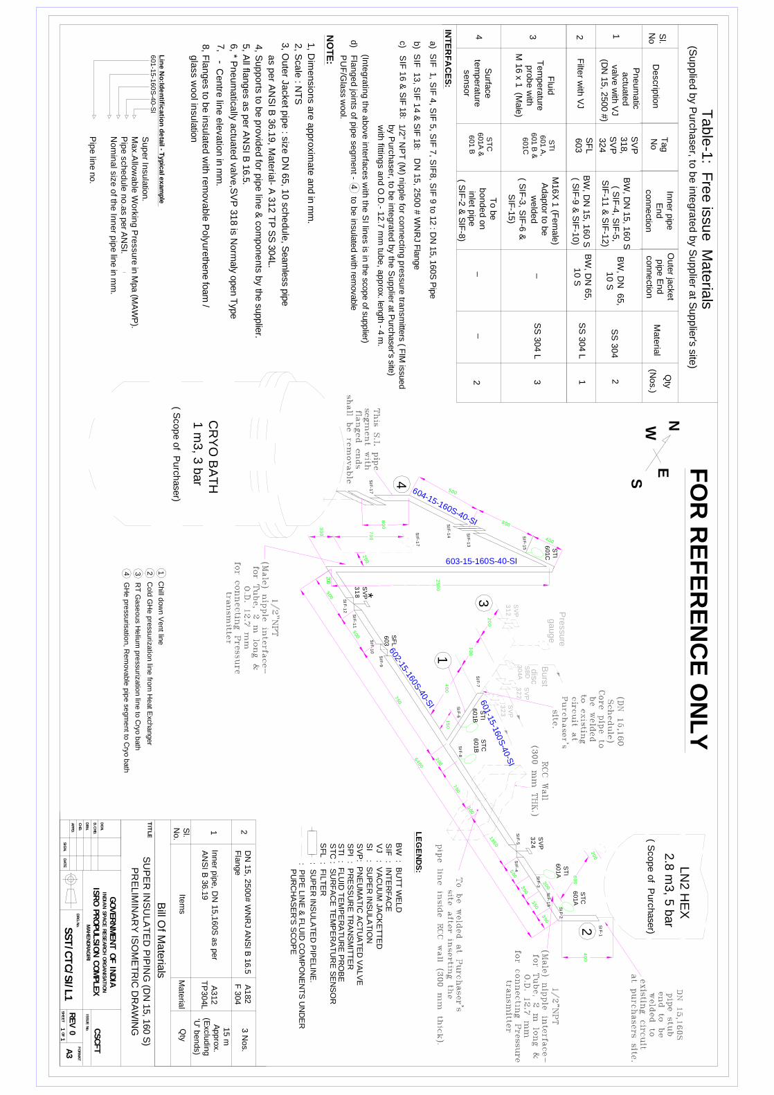
ST
I
60
1A
SI F
-3
400
185
0
500
SVP
318500
2500
800
2 00
ST
I
601C
SI F
-1
SI F
-4SI F
-5
SI F
-11
SI F
-12
SI F
-7
SI F
-13
SI F
-14
SI F
-17
SI F
-8SI F
-6
602-15-160S-40-S
I
603-15-160S-40-SI C
RY
O B
AT
H1
m3
, 3 b
ar
LN
2 H
EX
2.8
m3
, 5 b
ar
6400
2
3
4
3 R
T G
ase
ous H
eliu
m p
ressu
rizatio
n lin
e to
Cryo
bath
2 C
old
GH
e p
ressu
rizatio
n lin
e fro
m H
eat E
xchanger
4 G
He
pre
ssuris
atio
n, R
em
ova
ble
pip
e se
gm
ent to
Cryo
bath
1 C
hill d
ow
n V
ent lin
e
: SU
PE
R IN
SU
LA
TE
D P
IPE
LIN
E.
Su
pe
r Insu
latio
n.
Ma
x.A
llow
ab
le W
ork
ing
Pre
ssu
re in
Mpa (M
AW
P).
Pip
e s
ch
ed
ule
no
.as p
er A
NS
I.N
om
ina
l siz
e o
f the
Inn
er p
ipe lin
e in
mm
.
Pip
e lin
e n
o.
Lin
e N
o:Id
en
tifica
tion
de
tail - T
yp
ical e
xam
ple
601-1
5-1
60
S-4
0-S
I
1S
S 3
04 L
2 1
Pneum
atic
actu
ate
d v
alv
e w
ith V
J (D
N 1
5, 2
500 #
)
Inner p
ipe
End
conne
ction
Qty
Mate
rial
Tag
No
Descrip
tion
Sl.
No
Ta
ble
-1: F
ree
issu
e M
ate
rials
(Inte
gra
ting
the
ab
ove
inte
rface
s w
ith th
e S
I line
s is
in th
e sco
pe o
f supplie
r)
FO
R R
EF
ER
EN
CE
ON
LY
BW
, DN
15, 1
60 S
( SIF
-4, S
IF-5
,S
IF-1
1 &
SIF
-12)
SS
304
2
TIT
LE
DGN.
GOVERNMENT O
F IN
DIA
OF
MAHENDRAGIR
I
APPD.
DATE
SIG
N.
CHD.
SHEET
DRG.N
o.
DRN.
ISRO P
ROPULSIO
N C
OMPLEX
1 1
ISSUE N
o.
D.C
HD.
CSCFT
INDIA
N S
PACE R
ESEARCH O
RGANIS
ATIO
N
A3
FORMAT
REV 0
SU
PE
R IN
SU
LA
TE
D P
IPIN
G (D
N 1
5, 1
60 S
)P
RE
LIM
INA
RY
ISO
ME
TR
IC D
RA
WIN
G
LE
GE
ND
S:
INT
ER
FA
CE
S:
N
SW
E
SV
P318,
SV
P324
VJ : V
AC
UU
M JA
CK
ET
TE
DS
I : SU
PE
R IN
SU
LA
TIO
N
SF
L : F
ILT
ER
a) S
IF 1
, SIF
4, S
IF 5
, SIF
7, S
IF8
, SIF
9 to
12 : D
N 1
5, 1
60S
Pip
e
DN
15
, 25
00
# W
NR
J Fla
nge
Filte
r with
VJ
SF
L603
SST/C
TC/S
I/L1
SV
P: P
NE
UM
AT
IC A
CT
UA
TE
D V
ALV
ES
PI : P
RE
SS
UR
E T
RA
NS
MIT
TE
RS
TI : F
LU
ID T
EM
PE
RA
TU
RE
PR
OB
ES
TC
: SU
RF
AC
E T
EM
PE
RA
TU
RE
SE
NS
OR
3S
S 3
04 L
Flu
idT
em
pera
ture
pro
be w
ithM
16 x
1 (M
ale
)
ST
I6
01 A
,
601 B
&
601C
M16
X 1
(Fem
ale
)A
dapto
r to b
ew
eld
ed
2
Surfa
ce
tem
pera
ture
sensor
3
ST
C6
01A
&
601 B
To b
eb
onde
d o
nin
let p
ipe
Oute
r jacke
tp
ipe
End
conne
ction
BW
, DN
65,
10 S
BW
, DN
65,
10 S
_
BW
, DN
15, 1
60 S
( SIF
-9 &
SIF
-10)
( SIF
-2 &
SIF
-8)
( SIF
-3, S
IF-6
&S
IF-1
5)
SVP
324
SVP
323
SI F
-9
_
2, S
ca
le : N
TS
1, D
imensio
ns a
re a
ppro
xim
ate
and in
mm
.
4, S
upports
to b
e p
rovid
ed fo
r pip
e lin
e &
com
pone
nts
by th
e su
pplie
r.
NO
TE
:
Centre
line e
levatio
n in
mm
.-
5, A
ll flanges a
s p
er A
NS
I B 1
6.5
.
( Scope o
f Purch
ase
r)
( Scope o
f Purc
hase
r)
SIF
: INT
ER
FA
CE
ST
I
60
1B
_
d) F
lan
ge
d jo
ints
of p
ipe
se
gm
en
t - 4 to
be
insu
late
d w
ith re
mova
ble
PU
F/G
lass w
ool.
4
SF
L
603
: PIP
E L
INE
& F
LU
ID C
OM
PO
NE
NT
S U
ND
ER
PU
RC
HA
SE
R'S
SC
OP
E
BW
: BU
TT
WE
LD
Sl.
No
.Ite
ms
Ma
teria
l
Inn
er p
ipe
, DN
15
,16
0S
as p
er
AN
SI B
36.1
9A
312
TP
30
4L
1 2
Qty
6, * P
ne
um
atic
ally
actu
ate
d va
lve,S
VP
31
8 is N
orm
aly o
pen T
ype
as p
er A
NS
I B 3
6.1
9, M
ate
rial- A
312 T
P S
S 3
04L.
3, O
ute
r Jacket p
ipe : s
ize D
N 6
5, 1
0 s
chedule
, Seam
less p
ipe
Bill O
f Ma
teria
ls
15
m A
pp
rox.
(Exclu
din
g'U
' be
nds)
DN
15
, 25
00
# W
NR
J AN
SI B
16.5
Fla
nge
A1
82
F 3
04
SI F
-10
3 N
os.
b) S
IF 1
3, S
IF 1
4 &
SIF
18:
7,
604-15-160S-40-SI
c) S
IF 1
6 &
SIF
18:
1/2
" NP
T (M
) nip
ple
for c
on
ne
cting
pre
ssu
re tra
nsm
itters ( F
IM issu
ed
by P
urc
ha
ser, to
be
inte
gra
ted
by th
e S
up
plie
r at P
urch
ase
r's site)
with
fitting
s an
d O
.D.- 1
2.7
mm
tub
e, a
pp
rox. le
ngth
- 4 m
.
*
SB
D
30
4A
SVP
322
ST
C
60
1B
SVP
312
1
601-15-160
S-4
0-SI
Bu
rstd
isc
500
750
300
400
200
SI F
-15
150
800
400
ST
C
60
1A
350
350
SI F
-18
SI F
-2
(Nos.)
8, F
langes to
be in
sula
ted w
ith re
movable
Po
lyure
thene fo
am
/ g
lass w
ool in
sula
tion
700
SI F
-17
200
(Sup
plie
d b
y Purch
ase
r, to b
e in
tegra
ted
by S
upplie
r at S
upplie
r's site)
300
200
600
200
200
Pre
ssu
re g
au
ge
750
300
350
500

LN
2/L
OX
Dis
po
sal p
it
SV
P
324
SV
P3
18
SF
L
603
CR
YO
BA
TH
LN
2 H
EA
T
EX
CH
AN
GE
R
SV
P
312
SV
P
323
FO
R R
EF
ER
EN
CE
ON
LY
TIT
LE
DGN.
GOVERNMENT O
F IN
DIA
OF
MAHENDRAGIR
I
APPD.
DATE
SIG
N.
CHD.
SHEET
DRG.N
o.
DRN.
ISRO P
ROPULSIO
N C
OMPLEX
1 1
ISSUE N
o.
D.C
HD.
CSCFT
INDIA
N S
PACE R
ESEARCH O
RGANIS
ATIO
N
A3
FORMAT
REV 0
TE
NT
AT
IVE
LA
YO
UT
DR
AW
ING
FO
RS
UP
ER
INS
UL
AT
ED
PIP
ING
(DN
15
, 16
0S
)
SST/C
TC/S
I/LY-0
1
EQ
UIP
ME
NT
/PIP
E L
INE
(UN
DE
R S
CO
PE
OF
PU
RC
HA
SE
R)
PR
OP
OS
ED
S.I. P
IPE
LIN
E (U
ND
ER
SC
OP
E O
F S
UP
PL
IER
)
CR
YO
TE
ST
CE
LL
/ RO
OM
LN
2/L
OX
TA
NK
ER
PA
RK
ING
YA
RD
3 R
T G
ase
ou
s H
eliu
m p
ressu
riza
tion lin
e to
Cryo
bath
2 C
old
GH
e p
ressu
riza
tion
line
from
Heat E
xch
anger
4 G
He
pre
ssu
risa
tion
, Re
mo
va
ble
pip
e se
gm
ent to
Cryo
bath
1 C
hill d
ow
n V
ent lin
e
2 C
old
GH
e p
ressu
rizatio
n lin
e fro
m H
ea
t Exch
ang
er
GH
e p
ress
urisa
tion,
Re
mova
ble
pip
e se
gm
ent
to C
ryo b
ath
4
3 R
T G
ase
ou
s He
lium
pre
ssu
rizatio
n
line
to C
ryo b
ath
SV
P
322
SB
D3
04A
Bu
rst d
isc
1 C
hill d
ow
n V
en
t line

Annexure-A: Price Format for Super insulated (S.I.) piping
Sl. No. Description of item Quantity Unit Rate Total
1)
Design fabrication, testing, inspection, erection and acceptance testing of Super insulated (SI) pipelines with accessories.
1 set.
2)
Spare Vacuum feed through connectors – 2 Nos., Spare vacuum gauges 2 Nos. and spare ‘O’ rings & gaskets – 3 sets for the S.I. piping (cost break up to be provided)
_
Third Party Inspection Charges (lump sum)
Testing Charges for all the tests (If it is included in the quoted price then mention ‘INCLUDED’ and list of tests carried out).
Packing & Forwarding Charges, Freight, Taxes & duties, etc.
Grand Total