CONTENTS HOT INSULATION - Gujarat Narmada Valley ...MECH)-PRO6/SECTION 6-I… · CONTENTS . HOT...
22
GUJARAT NARMADA VALLEY FERTILIZERS COMPANY LIMITED 50000 MTPA PAC PROJECT SECTION 6 : ANNEXURE – 4.6 DESIGN PHILOSOPHY INSULATION - 1 - CONTENTS HOT INSULATION 1 Scope 2 General 3 Insulation Materials and Utilization 3.1 Blanket Insulation 3.2 Loose Material Insulation 3.3 Cord Insulation 3.4 Preformed Pipe Insulation 4 Heat Transfer Coefficients 5 Metal Jacketing 6 Flashing Stripes 7 Bands and Supports 8 Application of Insulation 8.1 Mechanical Equipment Insulation 8.2 Tank Insulation 8.3 Vessel Insulation 8.4 Piping Insulation 8.5 Insulation of Traced Piping 9 Personnel Protection 10 Insulation Details 10.1 Spherical Head 10.2 Vessel Skirt 10.3 Steam Tracing on Horizontal Vessels 10.4 Steam Tracing on Vertical Vessels 10.5 Steam Tracing on Piping 10.6 Vertical Piping 10.7 Horizontal Piping 10.8 Prefabricated Valve Cover 10.9 Vertical Piping and Interruptions at Flange 10.10 Protection Shield
Transcript of CONTENTS HOT INSULATION - Gujarat Narmada Valley ...MECH)-PRO6/SECTION 6-I… · CONTENTS . HOT...

GUJARAT NARMADA VALLEY FERTILIZERS COMPANY LIMITED 50000 MTPA PAC PROJECT
SECTION 6 : ANNEXURE – 4.6 DESIGN PHILOSOPHY INSULATION
- 1 -
CONTENTS
HOT INSULATION
1 Scope 2 General 3 Insulation Materials and Utilization 3.1 Blanket Insulation 3.2 Loose Material Insulation 3.3 Cord Insulation 3.4 Preformed Pipe Insulation 4 Heat Transfer Coefficients 5 Metal Jacketing 6 Flashing Stripes 7 Bands and Supports 8 Application of Insulation 8.1 Mechanical Equipment Insulation 8.2 Tank Insulation 8.3 Vessel Insulation 8.4 Piping Insulation 8.5 Insulation of Traced Piping 9 Personnel Protection 10 Insulation Details 10.1 Spherical Head 10.2 Vessel Skirt 10.3 Steam Tracing on Horizontal Vessels 10.4 Steam Tracing on Vertical Vessels 10.5 Steam Tracing on Piping 10.6 Vertical Piping 10.7 Horizontal Piping 10.8 Prefabricated Valve Cover 10.9 Vertical Piping and Interruptions at Flange 10.10 Protection Shield

GUJARAT NARMADA VALLEY FERTILIZERS COMPANY LIMITED 50000 MTPA PAC PROJECT
SECTION 6 : ANNEXURE – 4.6 DESIGN PHILOSOPHY INSULATION
- 2 -
1. Scope 1.1 This specification covers the requirements for hot insulation. 1.2 This specification also defines the general requirements for the material and application of
insulation and personnel protection to hot piping, vessels and equipment. 2. General 2.1 Hot piping, vessels and equipment operating at 60 °C or higher shall be insulated. The
insulation thickness depends on the operating temperature. The insulation material shal1 be • selected in accordance with the maximum expected operating temperature.
2.2 The extent and thickness of insulation shall be indicated on pipeline lists, piping
drawings. P & I Diagrams, and equipment data sheets. The insulation, material shall be selected prior to commencing work.
2.3 All surfaces to be insulated shall be dry and free of grease, dirt, loose paint, rust, mill scale,
etc. Primer, when specified, shall be completely dry. 2.4 Pressure test on pipe, vessels and equipment shall be completed and repairs shall be made
before insulation is installed. If insulation is applied before testing, all welds, threads, and flange connections shall be left exposed until completion of testing. Vessels being shop tested may be completely insulated. The installation of insulation prior to testing needs the written approval of the Owner.
2.5 The insulation shall be applied in single layers with staggered longitudinal joints.
Insulation layers shall be applied with the joints tight, except when loose insulation material is used.
2.6 All insulation material shall be protected from moisture and weather before and during
application If insulation should get wet before it is jacketed, it shall be thoroughly dried by heating the piping or equipment, or by other approved methods, before it is weather proofed. In case it is not possible to protect the applied insulation against weather with a metal sheet jacketing, foils or another wrapping material shall be used
2.7 No welding is allowed on vessels, piping, or structures. Bands, screws or wire shall be-
used to secure the insulation.
2.8 Equipment and Piping Specialties 2.8.1 Following valves, parts of equipment and piping shall not be insulated, except steam
service, personnel protection or specially indicated systems. a) Vessels: b) Manholes, nozzles and flanges. Vessels having internal insulation shall not be insulated outside unless '-specified
otherwise. b) Heat-Exchangers: c) Coolers: Flanges

GUJARAT NARMADA VALLEY FERTILIZERS COMPANY LIMITED 50000 MTPA PAC PROJECT
SECTION 6 : ANNEXURE – 4.6 DESIGN PHILOSOPHY INSULATION
- 3 -
Channel covers, cold side d) Valves and fittings: Control valves,' valves and fittings which require regular
dismantling, Expansion and rotating joints, vents, drains and steam traps. 2.8.2 Name plates, stamping and code inspection plates on vessels, heat exchangers, pumps,
compressors, etc. shall not be insulated. Suitable flashings shall be used and shall be sealed with temperature-resistant elastic weatherproofing to prevent entrance of water or moisture.
2.8.3 Insulation shall be stopped short of flange connections at a distance equal Ho the, bolt ,
length plus 10 mm. 2.8.4 Where pipe supports, pipe shoes, ladder and platform supports, nozzles, instrument
connections etc. protrude through the insulation, suitable flashings and sealing shall be used.
3 Insulation Materials and Utilization Mineral wool with chloride contents of more than 6 ppm or with free sulphur contents shall
not be used. Insulation material used on austenitic stainless steel piping, vessels and equipment shall be free of chlorides.
3.1 Blanket Insulation Density of insulation material shall be checked on regular intervals at site. 3.1.1 Mineral wool blankets first quality for temperatures up to 650 °C and with 80 to 100 kg/m3
density at 100 kg/m^2 surface pressure. The blankets are stitched at one side to hex mesh galvanized netting with metal wire.
3.1.3 The insulation blankets are cut to the outer insulation diameter and applied with the joints tight as follows: -
a) up to 100 mm insulation thickness 1-layer b) up to 200 mm insulation thickness 2-1ayers c) up to 300 mm insulation thickness 3- layers 3.1.4 On horizontal vessels and piping the longitudinal joint shall be located in the lower half of
the circumference. 3.1.5 Longitudinal and circumferential joints shall be secured with 1.0 irm diameter galvanized
wire or with steel hooks (6 hooks per running meter). All gaps shall be filled with loose, wool material.
3.1.6 Insulation shall be secured by bands for insulation diameter over 1000 mm (3 bands per running meter) .
3.1.7 Insulation thickness over 100 mm shall be applied in layers with longitudinal and circumferential joints staggered.
3.1.8 For hot insulation of SS piping & Equipment, all surface shall be covered with Aluminum foil of 0.1 MM thickness to protect SS from Chloride attack.
3.2 Loose Material Insulation 3.2.1 Pure, short fiber mineral wool of first quality, poor in enamel beads, suitable for
temperatures up to 700 *C shall be used for filler material. 3.2.2 Loose material shall be used where the application of insulation blankets is impossible. The
use of loose material insulation needs the written approval of the Owner. 3.2.3 The loose material is held by hex mesh galvanized netting. The loose material shall be
carefully padded in the area bounded by the hex mesh galvanized netting to reach a density of at least 160 till 180 kg/m3. Small gauge wire shall be used to sew the fill opening tight.
3.3 Cord Insulation

GUJARAT NARMADA VALLEY FERTILIZERS COMPANY LIMITED 50000 MTPA PAC PROJECT
SECTION 6 : ANNEXURE – 4.6 DESIGN PHILOSOPHY INSULATION
- 4 -
3.3.1 Mineral fiber cord shall be braided narrow meshed with steel wire. 3.3.2 The basic material shall consist of long fiber, mineral insulating material and shall only
contain binding material able to withstand the specified temperature. 3.3.3 Cord insulation shall only be used when the application of insulation blankets is impossible
and the use of loose material is technical impracticable. The use of.cord insulation needs the written approval of the Owner.
3.3.4 Cord insulation shall be wrapped tight around the object to be insulated and shall be compressed to the specified thickness.
3.3.5 The cord insulation shall be so manufactured that when wrapping the pipes it shall not get damaged, in order to avoid any falling out of the insulation material.
3.3.6 The layers are to be wrapped in opposite directions, when more than one layer of cord insulation is applied.
3.4 Preformed Insulation 3.4.1 Calcium silicate preformed pipe insulation for temperatures up to 800 °C and with 240 to
260 kg/m3 density. 3.4.2 Mineral wool preformed pipe insulation for temperatures up to 500 °C and with 160 kg/m3
density. 4 Heat Transfer Coefficients 4.1 Heat transfer coefficients (Lambda value) of insulation to be used shall not exceed the
values in the following chart:
Mean
Required
Mean
Required Temp.
Lambda Value
Temp.
Lambda
°C
W/mK
"C
W/mK 0
0.040
250
0,085 50
0,045
300
0.100 100
0,052
350
0,113 150
0,062
400
0,122 200
0,072
450
0,141
4.2 Certificates indicating the heat transfer coefficients with corresponding initial temperatures (mean temperature) and graw density of material to be used shall be shown upon . request to the Owner Site Management. The certificate is to be issued by an official accepted authority.
5 Metal Jacketing 5.1 Metal Jacketing shall be hot dip galvanized steel sheets or aluminium sheeting, applied as
described in the following paragraphs. 5.2 Steel sheet jacketing shall be applied as follows: 5.2.1 Steel sheets, hot dip galvanized, first quality (275 g zinc coat per m2) shall be used. 5.2.2 Sheet metal thickness in relation to the insulation circumference: Insulation Sheet metal circumference thickness Gauge No up to 0.5 m 0,63 rim 22 0,51 - 1,0m 0,75 mm 21 1,01 - 1,5 m 0,88 mm 20 over 1,5 m 1,0 mm 19 For Tanks 1,25 mm 17 (see para. 9.2.5)

GUJARAT NARMADA VALLEY FERTILIZERS COMPANY LIMITED 50000 MTPA PAC PROJECT
SECTION 6 : ANNEXURE – 4.6 DESIGN PHILOSOPHY INSULATION
- 5 -
5.2.3 All longitudinal joints shall be lapped 50 mm and shall be corrugated. 5.2.4 Circumferential laps shall be corrugated to reinforce the edges. 5.2.5 Sheet metal screws (ace. DIN 7971, stainless steel), pan head, self-tapping with 4,2 mm
diameter and 13 mm thread length shall be provided at 125 mm intervals. 5.2.6 Bands shall be 16 mn wide by 0.5 run thick, galvanized- or stainless steel banding. Seals
shall be galvanized or stainless steel. 5.2.7 If bands are used, they shall be located on the overlap near the joint and in between the joints
at max. 475 mm centers. 5.3 Aluminum sheet jacketing shall be applied as follows: 5.3.1 Smooth, medium hard salt air resisting aluminium (AlMnMg semi hard) shall be used 5.3.2 Sheet metal thickness in relation to the insulation circumference: Insulation Sheet metal Circumference thickness up to 0,5 m 0,6 mm 0,51 - 1,0 m 0,8 mm 1,01 - 1,5m 1,0 mm over 1,5 m 1,2 am 5.3.3 All longitudinal joints on vessels, heat exchangers or storage tanks shall be lapped 50 mm. 5.3.4. Circumferential laps shall be corrugated to reinforce the edges. 5.3.5 Sheet metal screws (ace. DIN 7971, stainless steel), pan head, self-tapping with 4,2 mm
diameter and 13 ran thread length shall be provided at 125 mm intervals 5.3.6. Bands shall be 16 am wide by 0,5 mm thick aluminum or stainless steel banding. Seals shall
be stainless steel. 5.3.7. If bands are used, they shall be located on the overlap near the joint and in between the joints
at max. 475 ran centers 5.4 Interruptions in the metal jacketing of piping and vessels e.g. at un insulated flanges shall be
stopped short by watertight metal flashing rings. Sealing band shall be installed on the not side of the ring. End caps are to be used for insulation circumference over 500 mm
5.5 Care should be taken when using galvanized mesh netting and wire or metal supports and aluminum jacketing. Plastic or other synthetic resin bands shall be installed to avoid contact between the dissimilar materials which might cause galvanic corrosion.
5.6 The radiant section around traced piping shall be fabricated from galvanized sheet metal
gauge 22 or from 0,6 mn thick aluminium sheeting. 6 Flashing Stripes 6.1 All longitudinal joints of metal jacketing in vertical pipes and all circumferential joints in
horizontal pipes shall be sealed by flashing stripes to prevent rainwater penetration into the insulation. This includes all interruptions in the metal jacketing of piping.
6.2 Flashing compound shall be a suitable weatherproofing for application between -20 and +70 °C. The material shall not support combustion, shall be permanent resilient, and durable under extreme weather conditions and shall adhere to pipe and insulation material,
7 Bands and Supports 7.1 Equipment and vessels are supplied with insulation supports, welding of supports to
equipment and vessels is not allowed. 7.2 Metal jacketing on piping and horizontal vessels shall be supported by rings installed at 950

GUJARAT NARMADA VALLEY FERTILIZERS COMPANY LIMITED 50000 MTPA PAC PROJECT
SECTION 6 : ANNEXURE – 4.6 DESIGN PHILOSOPHY INSULATION
- 6 -
mm spacing. 7.3 Elbows shall have support rings at the ends and in the middle. 7.4 Equipment up to 1000 mm circumference shall have support rings fabricated from 30 nrn
wide and 2 urn thick steel banding. Equipment over 1000 mm circumference shall have support rings fabricated from 30 mm wide and 3 mm thick banding. Ceramic cylinders of 16 mm diameter or metal bars shall be used for studs.
7.5 Support rings with metal studs shall have a 4 mn IT-sheet riveted between ring and studs to prevent contact between piping or equipment and metal jacketing.
7.6 The number of studs per ring is as follows: a) up to ON 100 (4 in.) - 5 Studs per circumference, b) up to ON 150 (6 in.) - 6 Studs per circumference c) up to ON 200 (8 in.) - 7 Studs per circumference d) up to ON 300 (12 in.) - 9,Studs per circumference e) up to ON 400 (16 in.) - 10 Studs per circumference f) up to ON 600 (24 in.) - 13 Studs per circumference g) up to ON 700 (28 in.) - 15 Studs per circumference At Nominal size over 700 (28 in.) and oval, angular cross section shall have a distance
between studs of not more than 250 mm, measured at the outer ring. 7.7 Band type support rings are tightened by hex head, or flat head bolts of min. 8 mn diameter. 7.8 Support rings on vertical vessels are welded or fitted to weld-on lugs at 3000 run spacing.
Support rings may be deleted for vessels having many nozzles. 7.9 Loose material insulation shall be supported by 2 rings per linear meter. 7.10 Because of the large variety of special supports available, the technical details and data of
the supports to be used shall be issued to Owner for approval prior to start of work. 8 Application of Insulation 8.1 Mechanical Equipment Insulation Equipment such as turbine- and pump bodies, heater fans, etc. shall be insulated as
indicated in the data sheets. Equipment requiring regular control- and maintenance service shall be provided with removable metal boxes. The insulation shall be attached to the inside of the box to avoid damage to the insulation when removing the box. Removable box shall be designed to fit close over such equipment and adjacent insulation.
8.2 Tank Insulation 8.2.1 Sheet edges are swaged for reinforcement and to tighten the joints. Galvanized banding 85
mm wide and 1 mm thick shall be riveted to the vertical sheet edges. Joints shall be lapped 70 mi. Galvanized sheet metal screws, self tapping with 4,8 mm diameter and 19 ran thread length shall be installed on 125 mm centers.
8.2.2 Tank roof sheeting shall be fabricated in equal sections, joints direction roof center. The joint overlap shall be folded vertically to stiffen the joint. All joints shall be folded double.
8.2.3 The connection between roof and shell metal jacketing shall be formed by a horizontally folded joint.
8.2.4 Flashing rings and rain deflectors shall be installed at all cutouts, such as nozzles, supports and other protrusions through the metal jacketing. Heavy fillets of flashing compound shall be applied to all possible sources of moisture penetration. Sheet metal screws shall be used to secure the deflectors and flashing rings to the metal jacketing.
8.2.5 Tank insulation shall be finished with sheet metal jacketing in accordance with Paragraph 5. Sheet thickness for the first 3 courses shall be 1,25 ran, gauge no 17, for the following courses and the roof a sheet thickness of 1 mm, Gauge No. 19 shall be used.
8.3 Vessel Insulation 8.3.1 Vertical vessels which have a significant difference in operating temperature between
bottom and top may be insulated with the insulating thickness in accordance with the difference in temperature.

GUJARAT NARMADA VALLEY FERTILIZERS COMPANY LIMITED 50000 MTPA PAC PROJECT
SECTION 6 : ANNEXURE – 4.6 DESIGN PHILOSOPHY INSULATION
- 7 -
8.3.2 Vertical vessels shall have insulation supports installed by vessel manufacturer. Additional support rings shall be added where the supports installed by the manufacturer are insufficient.
8.3.3 Insulation on vessels and tubular equipment shall be supported by insulation support rings at 950 mm maximum spacing in order to maintain an overall insulation thickness and to support the metal jacketing (insulation pieces shall be used as a lining, see paragraph 8.5). The same applies to band type support rings which are to be fastened by machine bolts as it is forbidden to weld support rings to vessels or equipment.
The insulation shall be secured in place to prevent longitudinal movement when equipment is in operation. Due to the difference in heat radiant it may be possible that different stresses occur which need reinforced supports. Also the temperature increase during start-up shall be taken into account.
8.3.4 Application and thickness of insulation vessels smaller than 600 iron outside diameter shall be the same as described for piping.
8.3.5 Removable insulation shall be provided at hand- and manholes. 8.3.6 Name plates, stamping and code inspection plates on vessels and other tubular equipment
shall remain visible, see paragraph 2.8.3. 8.3.7 Vessels and columns shall be insulated with material as derived under paragraph 3. Horizontal vessels shall have the jacketing joints located on the bottom half the vessel.
Sheet metal jacketing shall be applied staggered and the top sheet shall overlap the bottom sheet.
8.3.8 Vessels and columns operating above 250 °C shall have expansion joints between jacketing and insulation. Breather joints shall be provided in the metal jacketing and support rings.
8.3.9 Weatherproofing shall be fabricated from materials as described in paragraph 5. 8.3.10 The metal sheet jacketing shall be overlapped as follows: In horizontal direction = 50 mm In vertical direction = 50 mm. 8.3.11 Figure 2 shows insulation details for vessel skirts. 8.3.12 The overlaps of longitudinal joints shall be secured by sheet metal screws (DIN 7971 stainless steel) pan head, self tapping with a diameter of 4,5 mm and 13 on thread length at
125 mm intervals. 8.3.13 Metal sheet jacketing of large vessels shall be overlapped 80 mm and shall be secured by a
double row of sheet metal screws. The second row shall be offset. Distance between the two rows of screws shall be 40 mm.
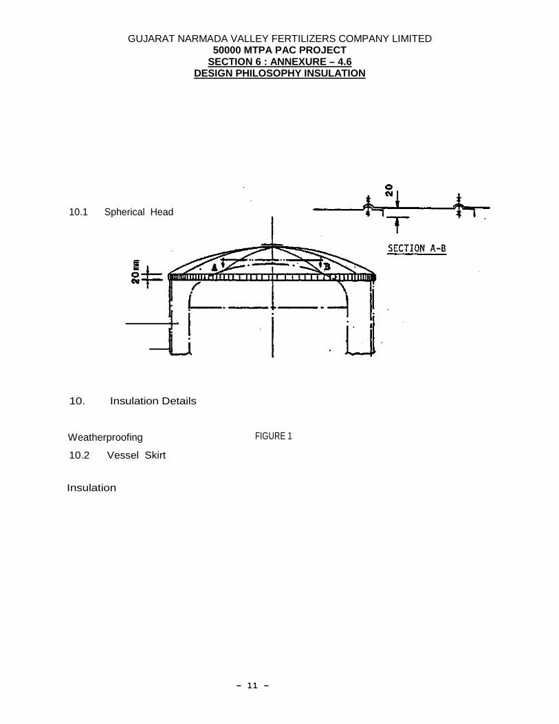
8.3.14 Circumferential laps shall be swaged for reinforcement. 8.3.15 Metal jacketing on arched heads shall be spherical shaped. The relationship between radius
and diameter of the insulated vessel is 1.1. The sections are at one side folded 90° downwards to gain a better rigidity. The height of the fold is 20 mm. All joints shall be secured in place with sheet metal screws installed in the center of the corrugated sheet edge.
8.3.16 8.3.17 For vessels with diameters below 1.0 meter the vessel head jacketing may be funnel
shaped. The funnel is inclined 20° and is preferred to the flat head jacketing. 8.3.18 A gear toothed chamfering machine shall be used to turn the edge of the metal head cover
20 mm to get an overlap over the straight side of the vessel. Head covers shall be secured in place by sheet metal screws.
8.3.19 Cutouts in the metal jacketing for nozzles, supports, handrails, etc. shall be finished with flashing rings and rain deflectors.
8.3.20 Vertical vessels having steam tracing installed at the bottom part are above the tracing provided with a ring of flat iron bar, tight welded to the vessel. The insulation shall be performed as a metal box cover. Thus, in case of leaks at the steam tracing that insulation

GUJARAT NARMADA VALLEY FERTILIZERS COMPANY LIMITED 50000 MTPA PAC PROJECT
SECTION 6 : ANNEXURE – 4.6 DESIGN PHILOSOPHY INSULATION
- 8 -
can be removed easily. The end of the insulation beneath the ring shall be of the bevel-type while the insulation
above the ring shall be provided with a rain deflector, in order to ensure an easy running off of the rain water. See figure 6 and 7.
8.3.21 Vertical vessels with skirt fireproofing shall have a rain deflector installed to assure rain water does not penetrate behind the fireproofing. The rain deflector shall be secured at the bottom support ring and shall overlap the fireproofing. See figure 2.
8.4 Piping Insulation 8.4.1 For description of insulation material see paragraph 3.1, 3.2, 3.3 and 3.4. 8.4.2 Insulation is applied to: a) Process piping and fittings for heat conservation or for processes with sensitive
temperature control. b) Flanges, nozzles and valves in steam service and pipes with tracing. c) Piping, flanges and valves subject to personnel protection. 8.4.3 Pipe insulation shall be applied in single layer blankets stitched to hex mesh galvanized
netting and cut to the outer insulation circumference. The insulation shall be secured with galvanized wire on 200 mm centers. The insulation joints shall be secured with 1.0 mm galvanized wire or with steel hooks. See paragraph 3.1.5.
8.4.4 When insulation is applied in more than one layer, each layer shall separately be secured by wire. The joints shall be staggered. Insulation with a thickness over 100 am shall be applied in two layers minimum. See paragraph 3.1.6 and 3.1.7.
8.4.5 Preformed pipe insulation may be applied as circumferential or half sections. The preformed sections shall be installed with the joints tight and shall be secured by gauge No.14 galvanized wire (8 wires each linear meter).
8.4.6 The insulation shall be covered with hot dip galvanized or aluminium sheeting as indicated under paragraph 5. The metal jacketing shall be carefully shaped, reinforced and secured with sheet metal screws, 4,2 mm diameter installed at 125 mm centers.
8.4.7 Circumferential laps shall be swaged for reinforcement. The top sheet shall always overlap the bottom sheet.(to prevent rain water to enter the joint). Longitudinal overlap shall be 50 mm.
8.4.8 Sheet metal weather proofing on piping in water service, not installed on pipe bridges and with insulation circumferences smaller than 0,6 mm may be applied with groove-in-groove joints.
8.4.9 Insulation supports shall be installed in accordance with paragraph 7. Insulation supports shall be installed on piping having insulation circumferences over 0,6 meter.
8.4.10 Insulation supports shall be stopped short of un insulated flange connections to allow easy removal of bolts. Insulation shall be cut square and the jacketing shall be finished with a flashing ring. The flashing ring shall be secured by turning the edges under the pipe metal jacketing. See paragraph 2.8.4 and 5.4.
8.4.11 Piping which is heat traced shall have the tracers included in the insulation. Care should be taken as to have the wire mesh over the tracers to avoid insulating material to cone between tracer and piping and to reduce heat transfer. See paragraph 8.5.
8.4.12 Insulation supports shall be provided at 4 meter intervals in vertical piping to carry the insulation weight.
Supports shall be fastened with clamps fabricated from 6 mm thick steel banding. Insulation support height shall extent up to 10 mm to 15 nm from metal jacketing to avoid metal contact between support and jacketing.
When using preformed insulation sections the insulation shall stop short approx. 25 mm under the insulation support.
Expansion filler material such as glass wool shall be installed between the lower edge of the insulation support and the preformed insulation section. Joint material shall be compressed

GUJARAT NARMADA VALLEY FERTILIZERS COMPANY LIMITED 50000 MTPA PAC PROJECT
SECTION 6 : ANNEXURE – 4.6 DESIGN PHILOSOPHY INSULATION
- 9 -
to a minimum thickness when installed. 8.4.13 Preformed insulation on horizontal piping in pipe bridges, tank farms, etc. shall have 50 nm
wide expansion joints to absorb longitudinal expansion. The joint material shall be glass wool or equal compressible material. Breather joints with
100 mn overlaps shall be provided in the weather proof jacketing. Horizontal piping insulated with preformed sections do not need insulation supports.
8.4.14 Distance between finished insulation surfaces and piping or other equipment shall be 50 nm minimum.
8.4.15 Horizontal piping elevated on shoes shall have the insulation continuous. 8.4.16 Insulated piping without shoes shall have the insulation cut away on the bottom side for a
distance of 150 ram on each side of the support unless otherwise indicated on piping detail drawings.
8.4 17 On lines of all sizes, elbows shall be insulated with mitred sectional covers. The number of mitres depends on the diameter of the elbow.
The number of mitres shall be choosen that at no place the insulation thickness will be thinner as required.
8.4.18 Covers If specified, valves and fittings shall be weather-proofed with galvanized or aluminium sheet
metal covers. Covers shall be prefabricated and shall consist of two sections as a minimum. The cover shall be easy to remove, shall fit close over the adjacent insulation and shall have
an inside diameter equal to the outside piping insulation diameter. Covers shall have the insulation permanent applied to the inside. See figure 13 and 14. Covers for piping with insulation thickness up to 100 nm shall have an insulation applied to
pipe insulation thickness. Covers for piping insulation thickness over 100 mm shall have an insulation applied of maximum 100 mm thick.
Covers shall be closed by a minimum of two lever locks riveted to the cover body. The distance between lever locks shall not exceed 250 mm for covers having an overall
length over 500 am. The lever locks shall be secured by galvanized pins or self-tapping sheet metal screws.
The lateral cover ends are formed by folded-in flashing rings. The top cover shall be shaped in a downwards slope. A gear toothed chamfering machine shall be used to turn the edge of the top cover 20 nm over the cylindrical cover body. The end and top sections are cut conform the joints of the cover body and secured by rivets.
Covers shall be installed raintight. The overall length of insulating covers shall be kept to the necessary minimum. The pipe
insulation shall be overlapped 50 mm on both sides. The cover tops shall be kept in the elevation when installed to valve batteries or manifolds. Valve glands shall remain free to enable adjustment of packings without removal of the
Insulation cover. See figure 15. over Definitions Flange covers: Cylindrical cover in 2 sections with 2 flashing rings. Figure 13 and 14
show a flange cover in horizontal and one in vertical direction Form covers: Multi-section flange cover and all flange covers with non-circular
flashing rings. Nozzle covers: Cylindrical cover in 2 sections with a branch smaller or equal cover
body diameter, rectangular installed and secured by rivets. Complicated covers: Covers with nozzles larger than body diameter or with nozzles inclined
less than 90° from horizontal, etc. Spherical covers, elbow covers and all further complicated insulation covers.
End covers: All flange covers with folded-in flashing rings. End covers are for jacketing of insulation stops at cylindrical part of vessels, for insulation stops on piping in front

GUJARAT NARMADA VALLEY FERTILIZERS COMPANY LIMITED 50000 MTPA PAC PROJECT
SECTION 6 : ANNEXURE – 4.6 DESIGN PHILOSOPHY INSULATION
- 10 -
of flanges and similar. The hub of the end cover is equal the insulation thickness. Covers shall be installed after insulation is applied and shortly before start-up. 8.4.19 Rain Deflectors Pipe supports, guides, shoes, etc. shall have rain deflectors fabricated from galvanized
sheet metal. The rain deflectors shall be applied to the metal jacketing by using heavy fillets of flashing compound. Vertical piping and insulation stops at flange connections shall have deflectors as shown in figure 10.
8.5 Insulation of Traced Piping 8.5.1 Piping which is heat traced shall have a heating zone installed prior to insulation application. The heating zone shall be fabricated from galvanized sheet metal when tracers
are parallel to piping. Aluminium foil 0,1 mn thick shall be used for wrapped tracers. See paragraph 9.4.11 and figure 6. (For radiant section sheeting see paragraph 5.6 and table).
9 Personnel Protection 9.1 Insulation for personnel protection shall be installed when the temperature of non insulated
surfaces of piping, vessels or equipment exceeds + 50 °C or 60 °C which ever is specified and when:
a) Hot piping elevation does not exceed 2 meter above operating floors or platforms. b) Hot piping and equipment is not more than 600 mn away from operating floors or platforms. 9.2 After installation of personnel protection insulation as stipulated in paragraph 9.1, the
surface temperature shall not exceed + 50 °C or + 60 °C, which ever is specified. 9.3 Horizontal vessels with diameter smaller than 1250 mn shall be completely covered by
personnel protection. Horizontal vessels with diameter over 1250 ran shall have the personnel protection extended up to 2000 mn above operating floor or platform. A watertight finish shall be applied where the personnel protection insulation terminates.
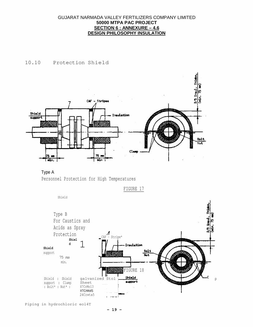
9.4 Uninsulated flange connections with extreme high operating temperatures shall have shields for personnel protection as indicated on the piping drawings. See figure 17 model A.
9.5 Uninsulated flange connections in caustic, acid or other etching services shall have shields for spray protection. See figure 17 model B.
9.6 Application of personnel protection insulation is conform to the application of hot insulation.
GUJARAT NARMADA VALLEY FERTILIZERS COMPANY LIMITED 50000 MTPA PAC PROJECT
SECTION 6 : ANNEXURE – 4.6 DESIGN PHILOSOPHY INSULATION
- 11 -
10. Insulation Details
10.1 Spherical Head
Weatherproofing FIGURE 1
10.2 Vessel Skirt
Insulation

GUJARAT NARMADA VALLEY FERTILIZERS COMPANY LIMITED 50000 MTPA PAC PROJECT
SECTION 6 : ANNEXURE – 4.6 DESIGN PHILOSOPHY INSULATION
- 12 -
Rain deflector
Vent openings in skirt shall remain open
oof 1
Fire-proof insulation
FIGURE 2
Radiator sheet touching the vessel,'wall
V)
Angle wiht eyes to secure tension
i
Radiator sheet

GUJARAT NARMADA VALLEY FERTILIZERS COMPANY LIMITED 50000 MTPA PAC PROJECT
SECTION 6 : ANNEXURE – 4.6 DESIGN PHILOSOPHY INSULATION
- 13 -
Ve sel

GUJARAT NARMADA VALLEY FERTILIZERS COMPANY LIMITED 50000 MTPA PAC PROJECT
SECTION 6 : ANNEXURE – 4.6 DESIGN PHILOSOPHY INSULATION
- 14 -
Detail A Spacer between trader and vessel wall
FIGURE 7
j Flat iron ring tight welded
Gone of galv. steel sheet
Sheet metal jacket
Tracer pipe Tension bands
Insulation
FIGURE 5
Radiator Sheet (screwed)
Radiator Sheet (screwed)
Insulation—I Insulation—,
Metal jacket Metal jacket — Tracer
Tracer
Vessel wall Spacer
Vessel wall Rain deflector
End cover End cover /Insulation support ring support ring
Detail A Tracer touching.the vessel wall
FIGURE 6

GUJARAT NARMADA VALLEY FERTILIZERS COMPANY LIMITED 50000 MTPA PAC PROJECT
SECTION 6 : ANNEXURE – 4.6 DESIGN PHILOSOPHY INSULATION
- 15 -
10.5 Steam Tracing Piping
Insulation Radiator sheet Tension band
Z Tracers with 1 radiator sheet each
FIGURE 9
Common radiator sheet for 2 tracers
FIGURE 10
1 Common radiator sheet for 3 tracers
FIGURE 11
Dimensions of the radiator sheets see next page
FIGURE 12
1 Tracer with radiator sheet
FIGURE 8
Angle

GUJARAT NARMADA VALLEY FERTILIZERS COMPANY LIMITED 50000 MTPA PAC PROJECT
SECTION 6 : ANNEXURE – 4.6 DESIGN PHILOSOPHY INSULATION
- 16 -
Dimensions of Radiator Sheets Tracer Size DN 20 ( d = 26.9 rnn)
DN (1) Process Pipe
Side Angle
Side Length
Stretched Length 2)
80
60
60
135 100
60
55
124 125
60
53
120 I5O
90
66
114 200
90
57
96 250
90
54
90 300
90
52
86 400
90
50
83 500
90
49
81 600
90
49
80 700
90
48
79 800
90
48
78 900
90
48
78 1000
90
48
78
Material: Double faced galvanized steel sheet No.22 = 0,63 mm thick 1 a fold quality, zinc layer 275 g / m2 1) Normally heating zones shall not be provided for process pipes DN 50 and smaller, valves, flanges, elbows or other irregular surfaces. Only in special cases heating zones of aluminum foil shall be applied. 2) For calculation the stretched length for a cannon radiator sheet over more tracers, the center distance shall be added to the above given length.

GUJARAT NARMADA VALLEY FERTILIZERS COMPANY LIMITED 50000 MTPA PAC PROJECT
SECTION 6 : ANNEXURE – 4.6 DESIGN PHILOSOPHY INSULATION
- 17 -
10.6 Vertical Piping
tO.7 Horizontal Piping
Insulation
Rain deflector
End cover
Insulation
Flashing-ping-.
Spacer
Quick lever locks
FIGURE 13
Quick lever locks
Insulation
5 mm Drip hole
FIGURE 14

GUJARAT NARMADA VALLEY FERTILIZERS COMPANY LIMITED 50000 MTPA PAC PROJECT
SECTION 6 : ANNEXURE – 4.6 DESIGN PHILOSOPHY INSULATION
- 18 -
10.8 Prefabricated Valve Cover
10.9 Interruptions at Flanges on Vertical Piping
Cover top
5 KM Drip hole _a - Insulation thickness
FIGURE 15
Rain deflector
End cover
Insulation
FIGURE 16
GUJARAT NARMADA VALLEY FERTILIZERS COMPANY LIMITED 50000 MTPA PAC PROJECT
SECTION 6 : ANNEXURE – 4.6 DESIGN PHILOSOPHY INSULATION
- 19 -
10.10 Protection Shield
Type A Personnel Protection for High Temperatures
Type B
FIGURE 17
For Caustics and Acids as Spray Protection
Shield
Shield support
75 ma min.
Piping in hydrochloric eol4T
Shield
lamp
CAP - Stripe*
1
FIGURE 18
Shield : Shield support : Clamp : Bolt* : Nut* :
galvanized Stol Sheet X7CrMo13 XTCrMolS 24Cr»ta5

GUJARAT NARMADA VALLEY FERTILIZERS COMPANY LIMITED 50000 MTPA PAC PROJECT
SECTION 6 : ANNEXURE – 4.6 DESIGN PHILOSOPHY INSULATION
- 20 -
service must h«v« th* •hi«U insid» prot*at»d with • HCL rwUting pmint
PHILOSOPHY FOR COLD INSULATION 1.0 This specification defines the requirements for the insulation in Feed Stock Conversion plant
for the purpose of cold insulation of Equipment and piping. 2.0 Purpose:- Purpose of this specification is to enable the insulation contractor to supply the proper
materials for insulation and to execute the work corresponding with the technical requirements.
3.0 Materials:- 3.1 Polyurethane foam slabs and pipe section having the following specification. Raw density - 36 Kg/m3 Thermal conductivity at tm. = 100C - 0.025 W/mk. Compressive strength at < 10% deformation - 0.15 N/mm2 3.2 Vapor barrier : Glass cloth sandwiched in between two layer of bitumen emulsion mastic
Gr. T-12 or equivalent. Glass cloth shall be of open weave 10-mesh type having glass fiber thickness of 5 mils. 3.3 Cushioning layer: Mineral wool felt, resin bonded. Density about 50 Kg/m³. 3.4 Adhesive; Blown bitumen type 85/25 confirming to IS702. 3.5 Joint Sealer : Cold bitumen 3.6 Bituminous primer on the surface of equipment 3.7 Sealing Compound: Suitable sealing compound for sheeting. Suitable sealing compound
must be approved by OWNER before use. 3.8 Screws: Self tapping screws 4.2mm diameter, 13mm long Material: Stainless steel SS 304 3.9 Tie wire: Galvanized Tie wire, 1.0mm 3.10 Steel band: Galvanized steel band 16 x 0.5mm 3.11 Metal jacketing: Aluminum sheet – IS737 Grade H2 Equipments - thickness 20 SWG Pipe up to 16” dia pipe size – thickness 22 SWG Pipe above 16” dia pipe size – thickness 20 SWG 4.0 Application: 4.1 After erection and painting of equipment and piping, and after acceptance of pressure test,

GUJARAT NARMADA VALLEY FERTILIZERS COMPANY LIMITED 50000 MTPA PAC PROJECT
SECTION 6 : ANNEXURE – 4.6 DESIGN PHILOSOPHY INSULATION
- 21 -
the insulation material shall be applied in the required thickness. Pipe surface must be cleaned & painted with bituminous primer before lagging the insulation material.
4.2 Providing vapor barrier consist of glass cloth sandwiched in between two layers of bitumen
emulsion mastic. 4.3 Special care must be taken on elbows and fittings. Apply extra layer of the vapor barrier to
achieve a sufficient vapor barrier at elbows and fittings. 4.4 On protrusions of the insulation the vapor barrier shall be wound up to the uninsulated
surface of the pipes and shall be smeared with sealing compound. 4.5 In order to protect the vapor barrier against damage by the screws of the metal jacketing, a
25mm thick mineral-wool felt shall be wrapped between foil and jacketing and shall be fastened with tie wire of 1mm thickness.
4.6 The metal sheets for weather proofing shall be cut to the size of the outer circumference of
insulation, oversized to achieve a minimum overlap of 50mm. 4.7 Along the edge of the overlapping sheet the edge shall be bent with an approx. angle of 300
towards the underlying metal sheet to ensure a tight metal contact. 4.8 This overlap shall be fastened by self-tapping screws, 4.2mm diameter and 13mm-thread
length, at 150mm center to center. 4.9 Where possible, all-longitudinal and circumferential laps shall be applied in a way to shed
rainwater. 4.10 If flanges and valves are to be insulated then they shall have removable covers made of
Aluminum sheet. 4.11 Polyurethane foam dust mixed with brown bitumen shall be packed lightly to fill all irregular
voids and at the contraction points. 5.00 Specifications for Hot & Cold type of Insulation, Acoustic Insulation, etc. will be reviewed on
case to case basis. 6.0 Safety Manual as per “Construction Philosophy”, Annex 4.5. shall be followed. 7.0 GNFC has a ISO 14001 Certification. During site installations, CONTRACTOR shall ensure
that following guidelines are followed:
GUIDE LINES FOR CONTRACTOR AS PER ISO-14001
A INSTRUCTIONS TO BE FOLLOWED BEFORE EXECUTION:- Gate pass for workers shall be obtained from required authority. Work permit shall be taken from relevant plant in charge before commencement of work. Proper scaffolding shall be prepared as per site requirement. Required material brought at site shall be stored properly at safe location.
Hazardous material if any shall be kept at safe location/allocated area with required safety

GUJARAT NARMADA VALLEY FERTILIZERS COMPANY LIMITED 50000 MTPA PAC PROJECT
SECTION 6 : ANNEXURE – 4.6 DESIGN PHILOSOPHY INSULATION
- 22 -
precautions. Required electrical connection to be made with isolation & safe protection device. B INSTRUCTIONS TO BE FOLLOWED DURING EXECUTION:-
Workers must wear safety helmet, hand gloves etc. as per safety requisite. Permit must be renewed in every shift from plant in charge as per issued work permit. Any leakage's occurs during work shall be immediately informed to safety dept./plant. Removed insulation material shall be cleared immediately from plant premised and kept at
specified location . Required electrical connections to be made with isolation and safe protection device. Waste insulating material, etc. shall be collected and disposed to scrap pit. Waste asbestos sheet shall be collected and handed over to concern group for storing at
specified location. Area of work during excavation, radiography, sand blasting shall be cordoned with warning
tags of "work in progress”, “no entry”, “radiography” in progress' etc. Spillage of oil if any on land during transformer charging and collected in pit shall be
recovered from pit and handed over to concern group. C INSTRUCTIONS TO BE FOLLOWED AFTER EXECUTION:- Site shall be cleared from any left out scrap material/waste on a day to day basis and finally
after completion of work. Balance useable material shall be return back to store/relevant place.
Any old recovered useable equipment/material shall be return back to store after thorough cleaning by operation group.
Aluminum Scrap removed from Existing Piping and Equipment shall be deposited in GNFC Scrap Yard. Aluminum Scrap generated during insulation work will be disposed off by Contractor outside GNFC.
Insulation Scrap and Debris removed from Existing Piping and Equipment as well as generated during new work shall be dumped in the area allocated within GNFC.
Disposal of Scrap (Aluminum as well as Insulation) will be done by Contractor at his cost. ( Labor as well as trailer ).