CONTENTS · Induction Heating Core Type Induction Furnace ... Since the material of the heating...
28
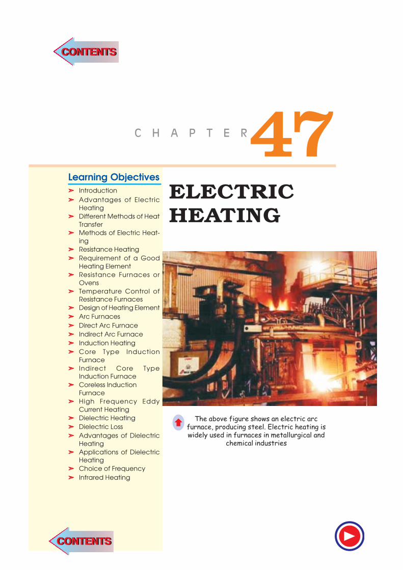
ELECTRIC HEATING "% + 0 ) 2 6 - 4 Learning Objectives ➣ Introduction ➣ Advantages of Electric Heating ➣ Different Methods of Heat Transfer ➣ Methods of Electric Heat- ing ➣ Resistance Heating ➣ Requirement of a Good Heating Element ➣ Resistance Furnaces or Ovens ➣ Temperature Control of Resistance Furnaces ➣ Design of Heating Element ➣ Arc Furnaces ➣ Direct Arc Furnace ➣ Indirect Arc Furnace ➣ Induction Heating ➣ Core Type Induction Furnace ➣ Indirect Core Type Induction Furnace ➣ Coreless Induction Furnace ➣ High Frequency Eddy Current Heating ➣ Dielectric Heating ➣ Dielectric Loss ➣ Advantages of Dielectric Heating ➣ Applications of Dielectric Heating ➣ Choice of Frequency ➣ Infrared Heating The above figure shows an electric arc furnace, producing steel. Electric heating is widely used in furnaces in metallurgical and chemical industries Ç CONTENTS CONTENTS
Transcript of CONTENTS · Induction Heating Core Type Induction Furnace ... Since the material of the heating...
ELECTRIC
HEATING
Learning Objectives
Introduction
Advantages of Electric
Heating
Different Methods of Heat
Transfer
Methods of Electric Heat-
ing
Resistance Heating
Requirement of a Good
Heating Element
Resistance Furnaces or
Ovens
Temperature Control of
Resistance Furnaces
Design of Heating Element
Arc Furnaces
Direct Arc Furnace
Indirect Arc Furnace
Induction Heating
Core Type Induction
Furnace
Indirect Core Type
Induction Furnace
Coreless Induction
Furnace
High Frequency Eddy
Current Heating
Dielectric Heating
Dielectric Loss
Advantages of Dielectric
Heating
Applications of Dielectric
Heating
Choice of Frequency
Infrared Heating
CONTENTS
CONTENTS
1834 Electrical Technology
47.1. Introduction
Electric heating is extensively used both for domestic and industrial applications. Domestic
applications include (i) room heaters (ii) immersion heaters for water heating (iii) hot plates for
cooking (iv) electric kettles (v) electric irons (vi) pop-corn plants (vii) electric ovens for bakeries
and (viii) electric toasters etc.
Industrial applications of electric heating include (i) melting of metals (ii) heat treatment of
metals like annealing, tempering, soldering and brazing etc. (iii) moulding of glass (iv) baking of
insulators (v) enamelling of copper wires etc.
47.2. Advantages of Electric Heating
As compared to other methods of heating using gas, coal and fire etc., electric heating is far
superior for the following reasons :
(i) Cleanliness. Since neither dust nor ash is produced in electric heating, it is a clean system
of heating requiring minimum cost of cleaning. Moreover, the material to be heated does
not get contaminated.
(ii) No Pollution. Since no flue gases are produced in electric heating, no provision has to be
made for their exit.
(iii) Economical. Electric heating is economical because electric furnaces are cheaper in their
initial cost as well as maintenance cost since they do not require big space for installation
or for storage of coal and wood. Moreover, there is no need to construct any chimney or to
provide extra heat installation.
(iv) Ease of Control. It is easy to control and regulate the temperature of an electric furnace
with the help of manual or automatic devices. Temperature can be controlled within ± 5°C
which is not possible in any other form of heating.
(v) Special Heating Requirement. Special heating requirements such as uniform heating of a
material or heating one particular portion of the job without affecting its other parts or
heating with no oxidation can be met only by electric heating.
(vi) Higher Efficiency. Heat produced electrically does not go away waste through the chim-
ney and other by products. Consequently, most of the heat produced is utilised for heating
the material itself. Hence, electric heating has higher efficiency as compared to other types
of heating.
(vii) Better Working Conditions. Since electric heating produces no irritating noises and also
the radiation losses are low, it results in low ambient temperature. Hence, working with
electric furnaces is convenient and cool.
(viii) Heating of Bad Conductors. Bad conductors of heat and electricity like wood, plastic and
bakery items can be uniformly and suitably heated with dielectric heating process.
(ix) Safety. Electric heating is quite safe because it responds quickly to the controlled signals.
(x) Lower Attention and Maintenance Cost. Electric heating equipment generally will not
require much attention and supervision and their maintenance cost is almost negligible.
Hence, labour charges are negligibly small as compared to other forms of heating.
47.3. Different Methods of Heat Transfer
The different methods by which heat is transferred from a hot body to a cold body are as
under:
1. Conduction
In this mode of heat transfer, one molecule of the body gets heated and transfers some of the
Electric Heating 1835
heat to the adjacent molecule and so on. There is a temperature gradient between the two ends of the
body being heated.
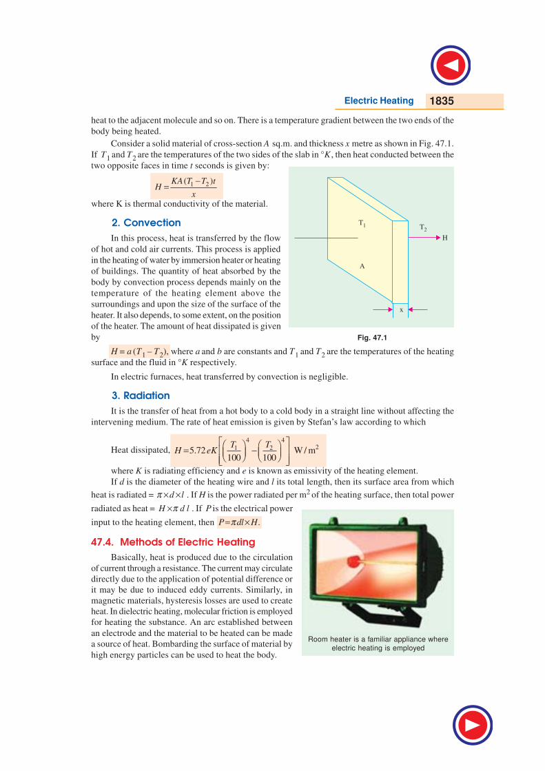
Consider a solid material of cross-section A sq.m. and thickness x metre as shown in Fig. 47.1.
If T1 and T2 are the temperatures of the two sides of the slab in °K , then heat conducted between the
two opposite faces in time t seconds is given by:
1 2( )KA T T tH
x
−=
where K is thermal conductivity of the material.
2. Convection
In this process, heat is transferred by the flow
of hot and cold air currents. This process is applied
in the heating of water by immersion heater or heating
of buildings. The quantity of heat absorbed by the
body by convection process depends mainly on the
temperature of the heating element above the
surroundings and upon the size of the surface of the
heater. It also depends, to some extent, on the position
of the heater. The amount of heat dissipated is given
by
H = a (T1 – T2), where a and b are constants and T1 and T2 are the temperatures of the heating
surface and the fluid in °K respectively.
In electric furnaces, heat transferred by convection is negligible.
3. Radiation
It is the transfer of heat from a hot body to a cold body in a straight line without affecting the
intervening medium. The rate of heat emission is given by Stefan’s law according to which
Heat dissipated,
4 421 25.72 W / m
100 100
T TH eK
= − where K is radiating efficiency and e is known as emissivity of the heating element.
If d is the diameter of the heating wire and l its total length, then its surface area from which
heat is radiated = d lπ × × . If H is the power radiated per m2 of the heating surface, then total power
radiated as heat = H d lπ× . If P is the electrical power
input to the heating element, then .P dl Hπ= ×
47.4. Methods of Electric Heating
Basically, heat is produced due to the circulation
of current through a resistance. The current may circulate
directly due to the application of potential difference or
it may be due to induced eddy currents. Similarly, in
magnetic materials, hysteresis losses are used to create
heat. In dielectric heating, molecular friction is employed
for heating the substance. An arc established between
an electrode and the material to be heated can be made
a source of heat. Bombarding the surface of material by
high energy particles can be used to heat the body.
Fig. 47.1
Room heater is a familiar appliance where
electric heating is employed
1836 Electrical Technology
Different methods of producing heat for general industrial and domestic purposes may be
classified below :
47.5. Resistance Heating
It is based on the I2R effect. When current is passed through a resistance element I2R loss takes
place which produces heat. There are two methods of resistance heating.
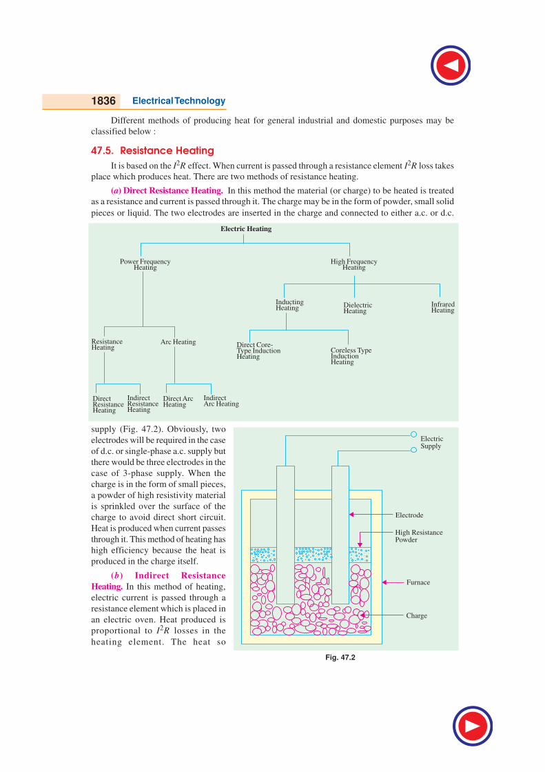
(a) Direct Resistance Heating. In this method the material (or charge) to be heated is treated
as a resistance and current is passed through it. The charge may be in the form of powder, small solid
pieces or liquid. The two electrodes are inserted in the charge and connected to either a.c. or d.c.
supply (Fig. 47.2). Obviously, two
electrodes will be required in the case
of d.c. or single-phase a.c. supply but
there would be three electrodes in the
case of 3-phase supply. When the
charge is in the form of small pieces,
a powder of high resistivity material
is sprinkled over the surface of the
charge to avoid direct short circuit.
Heat is produced when current passes
through it. This method of heating has
high efficiency because the heat is
produced in the charge itself.
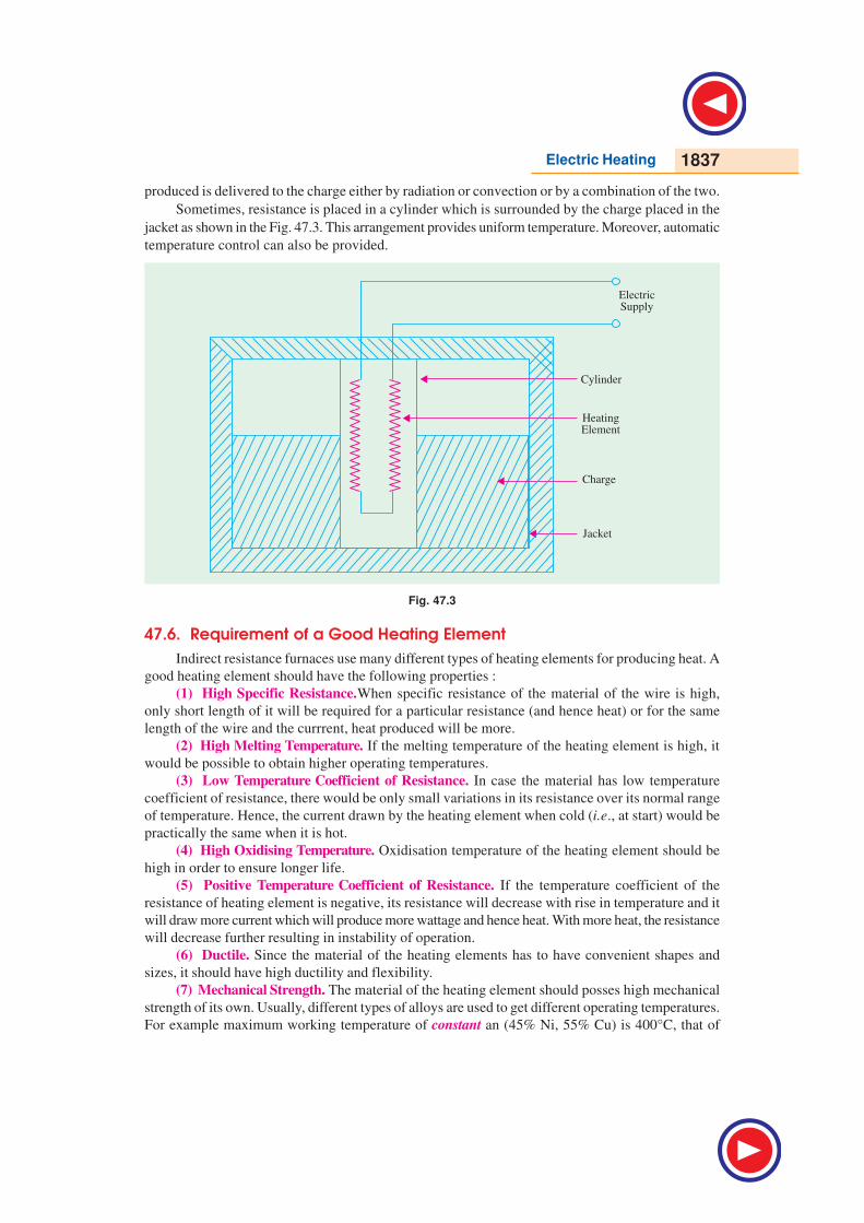
(b) Indirect Resistance
Heating. In this method of heating,
electric current is passed through a
resistance element which is placed in
an electric oven. Heat produced is
proportional to I2R losses in the
heating element. The heat so
Fig. 47.2
Electric Heating 1837
produced is delivered to the charge either by radiation or convection or by a combination of the two.
Sometimes, resistance is placed in a cylinder which is surrounded by the charge placed in the
jacket as shown in the Fig. 47.3. This arrangement provides uniform temperature. Moreover, automatic
temperature control can also be provided.
Fig. 47.3
47.6. Requirement of a Good Heating Element
Indirect resistance furnaces use many different types of heating elements for producing heat. A
good heating element should have the following properties :
(1) High Specific Resistance.When specific resistance of the material of the wire is high,
only short length of it will be required for a particular resistance (and hence heat) or for the same
length of the wire and the currrent, heat produced will be more.
(2) High Melting Temperature. If the melting temperature of the heating element is high, it
would be possible to obtain higher operating temperatures.
(3) Low Temperature Coefficient of Resistance. In case the material has low temperature
coefficient of resistance, there would be only small variations in its resistance over its normal range
of temperature. Hence, the current drawn by the heating element when cold (i.e., at start) would be
practically the same when it is hot.
(4) High Oxidising Temperature. Oxidisation temperature of the heating element should be
high in order to ensure longer life.
(5) Positive Temperature Coefficient of Resistance. If the temperature coefficient of the
resistance of heating element is negative, its resistance will decrease with rise in temperature and it
will draw more current which will produce more wattage and hence heat. With more heat, the resistance
will decrease further resulting in instability of operation.
(6) Ductile. Since the material of the heating elements has to have convenient shapes and
sizes, it should have high ductility and flexibility.
(7) Mechanical Strength. The material of the heating element should posses high mechanical
strength of its own. Usually, different types of alloys are used to get different operating temperatures.
For example maximum working temperature of constant an (45% Ni, 55% Cu) is 400°C, that of
1838 Electrical Technology
nichrome (50%, Ni 20% Cr) is 1150°C, that of Kantha (70% Fe, 25% Cr, 5% Al) is 1200° C and
that of silicon carbide is 1450°C.
With the passage of time, every heating element breaks open and becomes unserviceable.
Some of the factors responsible for its failure are :
(1) Formation of hot spots which shine brighter during operation, (2) Oxidation (3) Corrosion
(4) Mechanical failure.
47.7. Resistance Furnaces or Ovens
These are suitably-insulated closed chambers with a provision for ventilation and are used for
a wide variety of purposes including heat treatment of metals like annealing and hardening etc.,
stoving of enamelled wares, drying and baking of potteries, vulcanizing and hardening of synthetic
materials and for commercial and domestic heating. Temperatures upto 1000°C can be obtained by
using heating elements made of nickel, chromium and iron. Ovens using heating elements made of
graphite can produce temperatures upto 3000°C. Heating elements may consist of circular wires or
rectangular ribbons. The ovens are usually made of a metal framework having an internal lining of
fire bricks. The heating element may be located on the top, bottom or sides of the oven. The nature
of the insulating material is determined by the maximum temperature required in the oven.
An enclosure for charge which is heated by radiation or convection or both is called a heating
chamber.
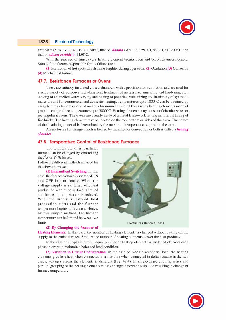
47.8. Temperature Control of Resistance Furnaces
The temperature of a resistance
furnace can be changed by controlling
the I2R or V2/R losses.
Following different methods are used for
the above purpose :
(1) Intermittent Switching. In this
case, the furnace voltage is switched ON
and OFF intermittently. When the
voltage supply is switched off, heat
production within the surface is stalled
and hence its temperature is reduced.
When the supply is restored, heat
production starts and the furnace
temperature begins to increase. Hence,
by this simple method, the furnace
temperature can be limited between two
limits.
(2) By Changing the Number of
Heating Elements. In this case, the number of heating elements is changed without cutting off the
supply to the entire furnace. Smaller the number of heating elements, lesser the heat produced.
In the case of a 3-phase circuit, equal number of heating elements is switched off from each
phase in order to maintain a balanced load condition.
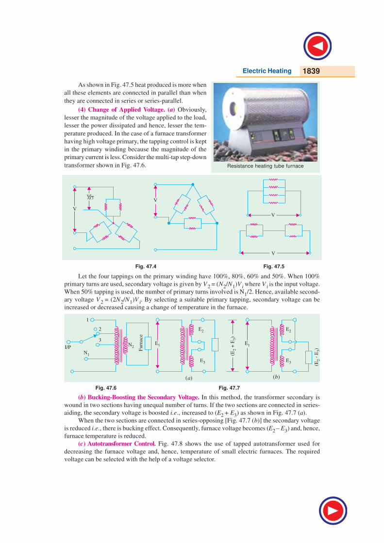
(3) Variation in Circuit Configuration. In the case of 3-phase secondary load, the heating
elements give less heat when connected in a star than when connected in delta because in the two
cases, voltages across the elements is different (Fig. 47.4). In single-phase circuits, series and
parallel grouping of the heating elements causes change in power dissipation resulting in change of
furnace temperature.
Electric resistance furnace
Electric Heating 1839
As shown in Fig. 47.5 heat produced is more when
all these elements are connected in parallel than when
they are connected in series or series-parallel.
(4) Change of Applied Voltage. (a) Obviously,
lesser the magnitude of the voltage applied to the load,
lesser the power dissipated and hence, lesser the tem-
perature produced. In the case of a furnace transformer
having high voltage primary, the tapping control is kept
in the primary winding because the magnitude of the
primary current is less. Consider the multi-tap step-down
transformer shown in Fig. 47.6.
Fig. 47.4 Fig. 47.5
Let the four tappings on the primary winding have 100%, 80%, 60% and 50%. When 100%
primary turns are used, secondary voltage is given by V2 = (N2/N1)V i where V i is the input voltage.
When 50% tapping is used, the number of primary turns involved is N1/2. Hence, available second-
ary voltage V2 = (2N2/N1)V i. By selecting a suitable primary tapping, secondary voltage can be
increased or decreased causing a change of temperature in the furnace.
Fig. 47.6 Fig. 47.7
(b) Bucking-Boosting the Secondary Voltage. In this method, the transformer secondary is
wound in two sections having unequal number of turns. If the two sections are connected in series-
aiding, the secondary voltage is boosted i.e., increased to (E2 + E3) as shown in Fig. 47.7 (a).
When the two sections are connected in series-opposing [Fig. 47.7 (b)] the secondary voltage
is reduced i.e., there is bucking effect. Consequently, furnace voltage becomes (E2 – E3) and, hence,
furnace temperature is reduced.
(c) Autotransformer Control. Fig. 47.8 shows the use of tapped autotransformer used for
decreasing the furnace voltage and, hence, temperature of small electric furnaces. The required
voltage can be selected with the help of a voltage selector.
Resistance heating tube furnace
(a) (b)

1840 Electrical Technology
Fig. 47.8 Fig. 47.9
(d) Series Reactor Voltage. In this case, a heavy-duty core-wounded coil is placed in series
with the furnace as and when desired. Due to drop in voltage across the impedence of the coil, the
voltage available across the furnace is reduced. With the help of D.P.D.T. switch, high/low, two-
mode temperature control can be obtained as shown in the Fig. 47.9. Since the addition of series coil
reduces the power factor, a power capacitor is simultaneously introduced in the circuit for keeping
the p.f. nearly unity. As seen, the inductor is connected in series, whereas the capacitor is in parallel
with the furnace.
47.9. Design of Heating Element47.9. Design of Heating Element47.9. Design of Heating Element47.9. Design of Heating Element47.9. Design of Heating Element
Normally, wires of circular cross-section or rectangular conducting ribbons are used as heating
elements. Under steady-state conditions, a heating element dissipates as much heat from its surface
as it receives the power from the electric supply. If P is the power input and H is the heat dissipated
by radiation, then P = H under steady-state conditions.
As per Stefan’s law of radiation, heat radiated by a hot body is given by
4 421 25.72 W / m
100 100
T TH eK
= − where T1 is the temperature of hot body in °K and T2 that of the cold body (or cold surroundings) in °K
2
2 2
4, and
/ 4
V l l lP R
R A d d
ρρ ρπ π
= = = =Now,
2 2 2 2
2 24 44 /
V d V l VP or
l ll d d
π πρ ρρ π
∴ = = =
...(i)
Total surface area of the wire of the element = (πd) × l
If H is the heat dissipated by radiation per second per unit surface area of the wire, then heat
radiated per second
= (πd) × l × H ...(ii)
Equating (i) and (ii), we have2 2
2 2
4( ) or ( ) or
4
d V d HP d l H d H
l l V
π ρπ πρ
= × × = × = ... (iii)
We can find the values of l and d from Eq. (i) and (iii) given above.
Ribbon Ribbon Ribbon Ribbon Ribbon TTTTType Elementype Elementype Elementype Elementype Element
If w is the width of the ribbon and t its thickness, then
2 2 2 2 2/
/ /
V V V wtV t VP or
R l A l Twt l wt Pρ ρ ρ ρ= = = = = ...(iv)

Electric Heating 1841
Heat lost from ribbon surface = 2wl H (neglecting the side area 2tl )
2
2 2
22 or
wtV t HwlH
l l V
ρρ
∴ = = ...(v)
Values of l and w for a given ribbon of thickness t can be found from Eqn. (iv) and (v) given
above.
Example 47.1. A resistance oven employing nichrome wire is to be operated from 220 V
single-phase supply and is to be rated at 16 kW. If the temperature of the element is to be limited to
1,170°C and average temperature of the charge is 500°C, find the diameter and length of the
element wire.
Radiating efficiency = 0.57, Emmissivity=0.9, Specific resistance of nichrome=(109 ×10–8)
ohm-m. (Utili. of Elect. Energy, Punjab Univ.)
Solution. P = 16 kW = 16,000 W
From Article 47.9,
2 2
2 8
(220)2,179,660
4 4 109 10 16,000
l V
Pd−
π π ×= = =ρ × × × ... (i)
Now,
4 4 4 421 2 1443 773
5.72 / m 5.72 0.9 0.57100 100 100 100
T TH eK W
= − = × × − = 116,752 W/m2
Now, total heat dissipated/s = electrical power input
( ) 116,752 16,000; 0.0436d l dlπ∴ × × = ∴ =or d 2 l 2 = 0.0019 ...(ii)
From Eqn. (i) and (ii), l3 = 2,179,660 × 0.0019 = 4141
∴ l = 16.05 m
d = 0.0436/16.05 = 2.716 × 10 –3 m = 2.716 mm
Example 47.2. A 30-kW, 3-φ, 400-V resistance oven is to employ nickel-chrome strip
0.254 mm thick for the three star-connected heating elements. If the wire temperature is to be
1,100°C and that of the charge to be 700°C, estimate a suitable width for the strip. Assume emissiv-
ity = 0.9 and radiating efficiency to be 0.5 and resistivity of the strip material is 101.6 × 10⁻⁸ Ω - m.
What would be the temperature of the wire if the charge were cold ?
(Utili. of Elect. Power A.M.I.E. Sec. B)
Solution. Power/phase = 30 × 1000/3 = 10,000 W, Vph = 400 / 3 231V=
If R is the resistance of the strip, R = 2phV
/P = 2312/10,000 = 5.34 Ω
Resistance of the strip,
3
8
5.34 0.245 101335
101.6 10
l lR or
wt w
ρ −
−× ×= = =
× ...(i)
Heat dissipated from surface of the strip,
4 421373 973
5.72 0.9 0.5 68,400 W/m100 100
H = × × − =
Surface area of the strip = 2wl; Total heat dissipated = 2wl × H
∴ 68,400 × 2 × wl = 10,000 or wl = 0.0731 ...(ii)
From Eqn. (i) and (ii), we get w = 0.0731/1335 or w = 7.4 mm
1842 Electrical Technology
Example 47.3. A cubic water tank has surface area of 6.0 m2 and is filled to 90% capacity six
times daily. The water is heated from 20°C to 65°C. The losses per square metre of tank surface per
1°C temperature difference are 6.3 W. Find the loading in kW and the efficiency of the tank. Assume
specific heat of water = 4,200 J/kg/°C and one kWh = 3.6 MJ. (A.M.I.E. Sec. B)
Solution. If l is the side of the tank, then total surface area of the tank = 6l2
∴ 6l2 = 6 or l = 6/6 = 1 m2
Volume of the tank = l3 = 1m3
Volume of water to be heated daily = 6 × (1 × 0.9) = 5.4 m3
Since 1m3 of water weighs 1000 kg, mass of water to be heated daily = 5.4 × 1000 = 5400 kg
Heat required to raise the temperature of water = 5400 × 4200 (65 – 20) = 1020 MJ = 1020/3.6
= 283.3 kWh
Daily loss from the surface of the tank = 6.3 × 6 × (65 – 20) × 24/1000 = 40.8 kWh
Energy supplied per day = 283.3 + 40.8 = 324.1 kWh
Loading in kW = 324.1/24 = 3.5 kW
Efficiency of the tank = 283.3 × 100/324.1 = 87.4%
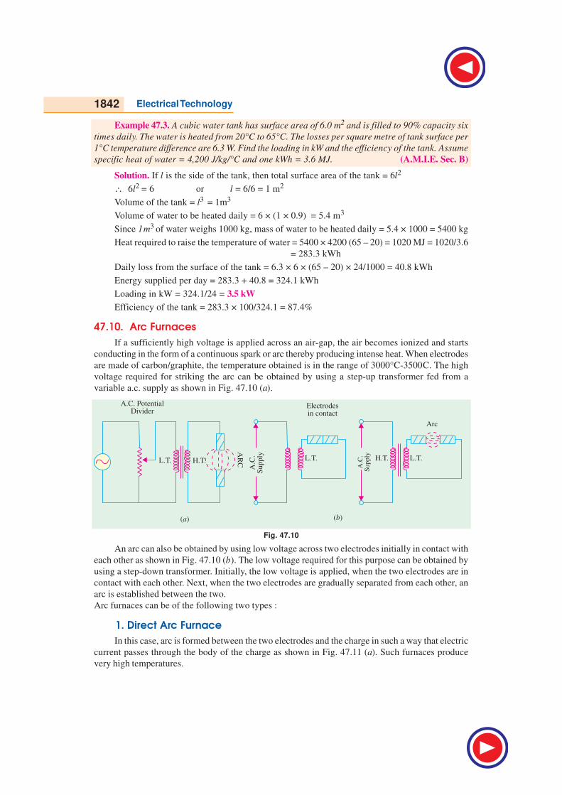
47.10. Arc Furnaces
If a sufficiently high voltage is applied across an air-gap, the air becomes ionized and starts
conducting in the form of a continuous spark or arc thereby producing intense heat. When electrodes
are made of carbon/graphite, the temperature obtained is in the range of 3000°C-3500C. The high
voltage required for striking the arc can be obtained by using a step-up transformer fed from a
variable a.c. supply as shown in Fig. 47.10 (a).
Fig. 47.10
An arc can also be obtained by using low voltage across two electrodes initially in contact with
each other as shown in Fig. 47.10 (b). The low voltage required for this purpose can be obtained by
using a step-down transformer. Initially, the low voltage is applied, when the two electrodes are in
contact with each other. Next, when the two electrodes are gradually separated from each other, an
arc is established between the two.
Arc furnaces can be of the following two types :
1. Direct Arc Furnace
In this case, arc is formed between the two electrodes and the charge in such a way that electric
current passes through the body of the charge as shown in Fig. 47.11 (a). Such furnaces produce
very high temperatures.
Electric Heating 1843
2. Indirect Arc Furnace
In this case, arc is formed between the two electrodes and the heat thus produced is passed on
to the charge by radiation as shown in Fig. 47.11 (b).
Fig. 47.11
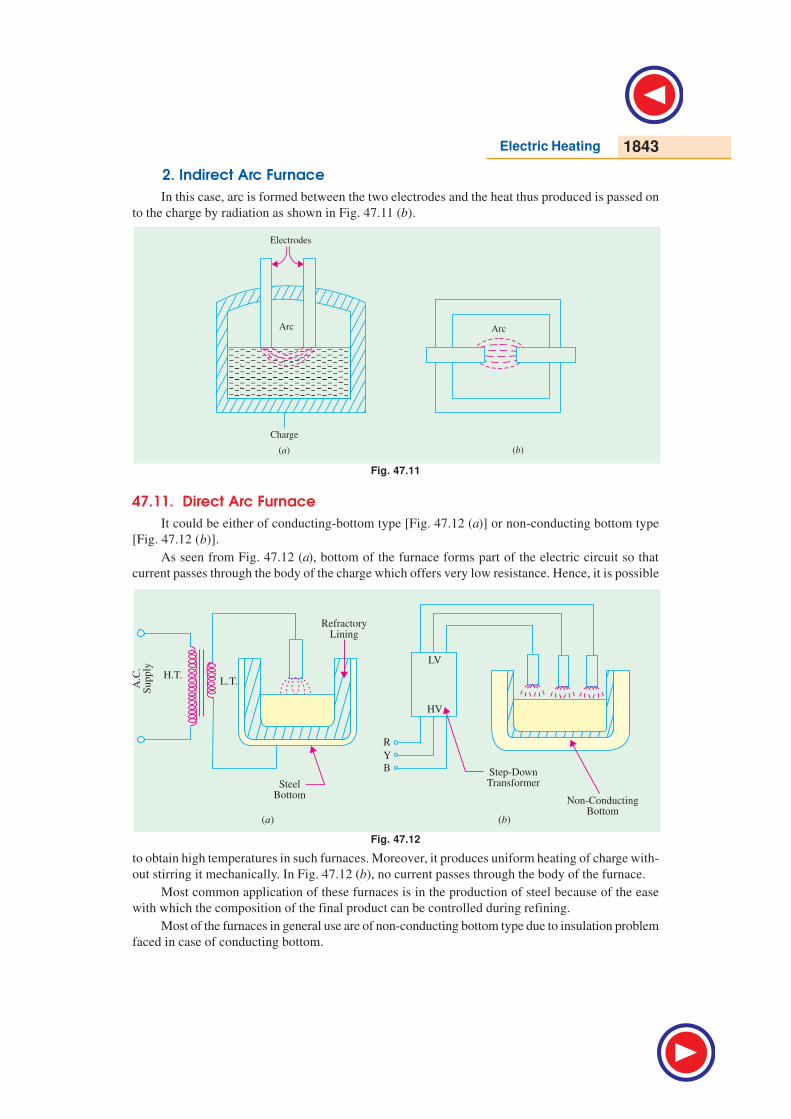
47.11. Direct Arc Furnace
It could be either of conducting-bottom type [Fig. 47.12 (a)] or non-conducting bottom type
[Fig. 47.12 (b)].
As seen from Fig. 47.12 (a), bottom of the furnace forms part of the electric circuit so that
current passes through the body of the charge which offers very low resistance. Hence, it is possible
Fig. 47.12
to obtain high temperatures in such furnaces. Moreover, it produces uniform heating of charge with-
out stirring it mechanically. In Fig. 47.12 (b), no current passes through the body of the furnace.
Most common application of these furnaces is in the production of steel because of the ease
with which the composition of the final product can be controlled during refining.
Most of the furnaces in general use are of non-conducting bottom type due to insulation problem
faced in case of conducting bottom.

1844 Electrical Technology
47.12. Indirect ArcFurnace
Fig. 47.13 shows a
single-phase indirect arc
furnace which is
cylindrical in shape. The
arc is struck by short-
circuiting the electrodes
manually or automatically
for a moment and then,
withdrawing them apart.
The heat from the arc and
the hot refractory lining is
transferred to the top layer
of the charge by radiation.
The heat from the hot top
layer of the charge is
further transferred to other parts of the charge by conduction.
Since no current passes through the body of the charge, there is no inherent stirring action due
to electro-magnetic forces set up by the current. Hence, such furnaces have to be rocked continuously
in order to distribute heat uniformly by
exposing different layers of the charge
to the heat of the arc. An electric motor
is used to operate suitable grinders and
rollers to impart rocking motion to the
furnace. Rocking action provides not
only thorough mixing of the charge, it
also increases the furnace efficiency in
addition to increasing the life of the
refractory lining material. Since in this
furnace, charge is heated by radiation
only, its temperature is lower than that
obtainable in a direct arc furnace. Such
furnaces are mainly used for melting non-
ferrous metals although they can be used
in iron foundaries where small quantities
of iron are required frequently.
Example 47.4. A 4-phase electric arc furnace has the following data :
Current drawn = 5000 A ; Arc voltage = 50 V
Resistance of transformer referred to secondary = 0.002 ΩResistance of transformer referred to secondary = 0.004 Ω
(i) Calculate the power factor and kW drawn from the supply.
(ii) If the overall efficiency of the furnace is 65%, find the time required to melt 2 tonnes of
steel if latent heat of steel = 8.89 kcal/kg, specific heat of steel = 0.12, melting point of
steel = 1370°C and initial temperature of steel = 20°C.
(Utilisation of Elect. Power, A.M.I.E. Sec. B)
Solution. Voltage drop due to transformer resistance = 5000 × 0.002 = 10 V
Voltage drop due to transformer reactance = 5000 × 0.004 = 20 V.
Motten aluminum
Cement MaterialRecycled Metal
Residual AshTapping
Hole
Gas Inlet
Aluminum Dross
Gas Exhaust
Carbon
Electrode
Carbon
Electrode
Residual Ash
Molten Aluminum
Arc
Rotary Furnace
Schematic view of an indirect electric arc furnace
Fig. 47.13
Electric Heating 1845
Since arc voltage drop is resistive in nature, it is vectorially added to the transformer resistance
drop.
Open circuit transformer secondary voltage/phase = 2 2(50 10) 20 63.25V+ + =
(i) Supply p.f.= (50 + 10)/63.25 = 0.9487
Power drawn/phase by the secondary = 5000 × 63.25 × 0.9487 = 300,000 W = 300 kW
Total power drawn from the supply = 3 × 300 = 900 kW
(ii) Energy required to melt 2 tonnes of steel = ms (t2 – t1) + mL = 2000 × 0.12 × (1370 – 20)
+ 2000 × 8.89 = 341,780 kcal.= 341,780/860 = 397.4 kWh
Power actually utilised = 900 × 0.65 = 585 kW
Time required for melting steel = 397.4/585 = 0.679 hours = 40 minutes 46 seconds.
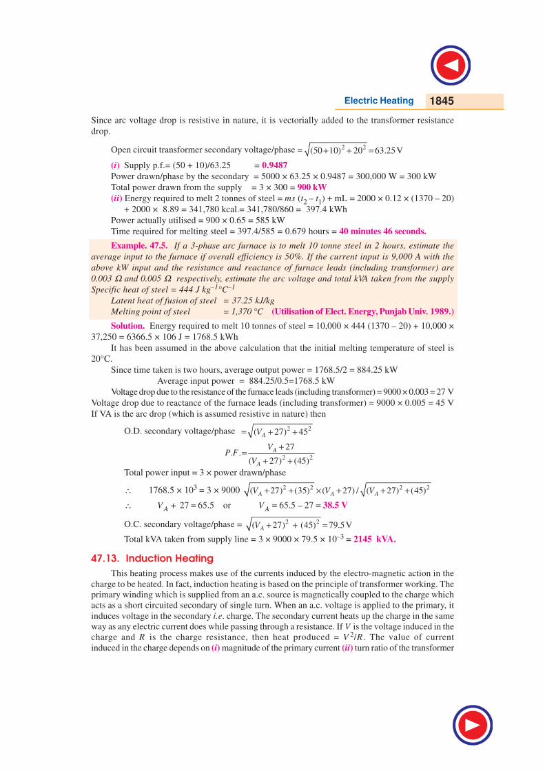
Example. 47.5. If a 3-phase arc furnace is to melt 10 tonne steel in 2 hours, estimate the
average input to the furnace if overall efficiency is 50%. If the current input is 9,000 A with the
above kW input and the resistance and reactance of furnace leads (including transformer) are
0.003 Ω and 0.005 Ω respectively, estimate the arc voltage and total kVA taken from the supply
Specific heat of steel = 444 J kg–1°C–1
Latent heat of fusion of steel = 37.25 kJ/kg
Melting point of steel = 1,370 °C (Utilisation of Elect. Energy, Punjab Univ. 1989.)
Solution. Energy required to melt 10 tonnes of steel = 10,000 × 444 (1370 – 20) + 10,000 ×
37,250 = 6366.5 × 106 J = 1768.5 kWh
It has been assumed in the above calculation that the initial melting temperature of steel is
20°C.
Since time taken is two hours, average output power = 1768.5/2 = 884.25 kW
Average input power = 884.25/0.5=1768.5 kW
Voltage drop due to the resistance of the furnace leads (including transformer) = 9000 × 0.003 = 27 V
Voltage drop due to reactance of the furnace leads (including transformer) = 9000 × 0.005 = 45 V
If VA is the arc drop (which is assumed resistive in nature) then
O.D. secondary voltage/phase 2 2( 27) 45AV= + +
2 2
27. .
( 27) (45)
A
A
VP F
V
+=
+ +Total power input = 3 × power drawn/phase
∴ 1768.5 × 103 = 3 × 9000 2 2 2 2( 27) (35) ( 27) / ( 27) (45)A A AV V V+ + × + + +
∴ VA + 27 = 65.5 or VA = 65.5 – 27 = 38.5 V
O.C. secondary voltage/phase = 2 2( 27) (45) 79.5VAV + + =
Total kVA taken from supply line = 3 × 9000 × 79.5 × 10–3 = 2145 kVA.
47.13. Induction Heating
This heating process makes use of the currents induced by the electro-magnetic action in the
charge to be heated. In fact, induction heating is based on the principle of transformer working. The
primary winding which is supplied from an a.c. source is magnetically coupled to the charge which
acts as a short circuited secondary of single turn. When an a.c. voltage is applied to the primary, it
induces voltage in the secondary i.e. charge. The secondary current heats up the charge in the same
way as any electric current does while passing through a resistance. If V is the voltage induced in the
charge and R is the charge resistance, then heat produced = V 2/R . The value of current
induced in the charge depends on (i) magnitude of the primary current (ii) turn ratio of the transformer
1846 Electrical Technology
(iii) co-efficient of magnetic
coupling.
Low-frequency induction
furnaces are used for melting and
refining of different metals.
However, for other processes like
case hardenning and soldering
etc., high-frequency eddy-current
heating is employed. Low-
frequency induction furnaces
employed for the melting of
metals are of the following two
types :
(a) Core-type Furnaces —
which operate just like a two wind-
ing transformer. These can be further sub-divided into (i) Direct core-type furnaces (ii) Vertical
core-type furnaces and (iii) Indirect core-type furnaces.
(b) Coreless-type Furnaces — in which an inductively-heated element is made to transfer
heat to the charge by radiation.
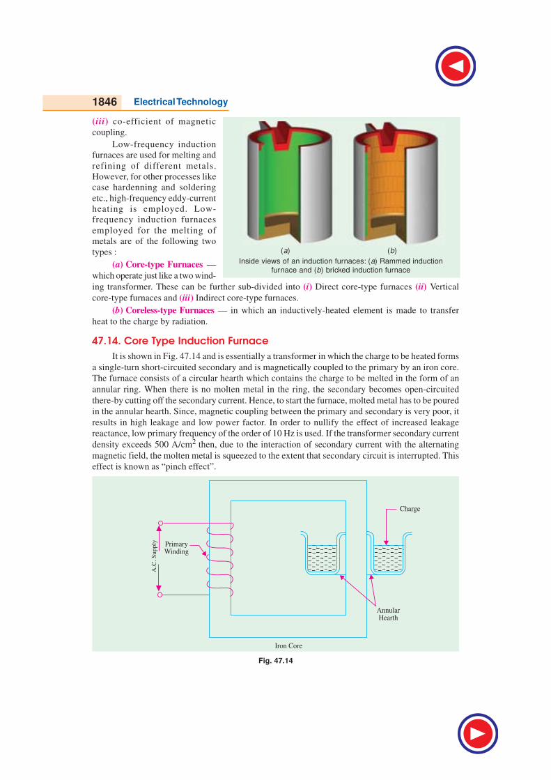
47.14. Core Type Induction Furnace
It is shown in Fig. 47.14 and is essentially a transformer in which the charge to be heated forms
a single-turn short-circuited secondary and is magnetically coupled to the primary by an iron core.
The furnace consists of a circular hearth which contains the charge to be melted in the form of an
annular ring. When there is no molten metal in the ring, the secondary becomes open-circuited
there-by cutting off the secondary current. Hence, to start the furnace, molted metal has to be poured
in the annular hearth. Since, magnetic coupling between the primary and secondary is very poor, it
results in high leakage and low power factor. In order to nullify the effect of increased leakage
reactance, low primary frequency of the order of 10 Hz is used. If the transformer secondary current
density exceeds 500 A/cm2 then, due to the interaction of secondary current with the alternating
magnetic field, the molten metal is squeezed to the extent that secondary circuit is interrupted. This
effect is known as “pinch effect”.
Fig. 47.14
Inside views of an induction furnaces: (a) Rammed induction
furnace and (b) bricked induction furnace
(a) (b)
Electric Heating 1847
This furnace suffers from the following drawbacks :
1. It has to be run on low-frequency supply which entails extra expenditure on motor-generator
set or frequency convertor.
2. It suffers from pinching effect.
3. The crucible for charge is of odd shape and is very inconvenient for tapping the molten
charge.
4. It does not function if there is no molten metal in the hearth i.e. when the secondary is
open. Every time molten metal has to be poured to start the furnace.
5. It is not suitable for intermittent service.
However, in this furnace, melting is rapid and clean and temperature can be controlled easily.
Moreover, inherent stirring action of the charge by electro-magnetic forces ensures greater uniformity
of the end product.
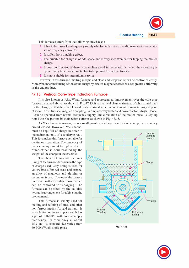
47.15. Vertical Core-Type Induction Furnace
It is also known as Ajax-Wyatt furnace and represents an improvement over the core-type
furnace discussed above. As shown in Fig. 47.15, it has vertical channel (instead of a horizontal one)
for the charge, so that the crucible used is also vertical which is convenient from metallurgical point
of view. In this furnace, magnetic coupling is comparatively better and power factor is high. Hence,
it can be operated from normal frequency supply. The circulation of the molten metal is kept up
round the Vee portion by convection currents as shown in Fig. 47.15.
As Vee channel is narrow, even a small quantity of charge is sufficient to keep the secondary
circuit closed. However, Vee channel
must be kept full of charge in order to
maintain continuity of secondary circuit.
This fact makes this furnace suitable for
continuous operation. The tendency of
the secondary circuit to rupture due to
pinch-effect is counteracted by the
weight of the charge in the crucible.
The choice of material for inner
lining of the furnace depends on the type
of charge used. Clay lining is used for
yellow brass. For red brass and bronze,
an alloy of magnetia and alumina or
corundum is used. The top of the furnace
is covered with an insulated cover which
can be removed for charging. The
furnace can be tilted by the suitable
hydraulic arrangement for taking out the
molten metal.
This furnace is widely used for
melting and refining of brass and other
non-ferrous metals. As said earlier, it is
suitable for continuous operation. It has
a p.f. of 0.8-0.85. With normal supply
frequency, its efficiency is about
75% and its standard size varies from
60-300 kW, all single-phase. Fig. 47.15
1848 Electrical Technology
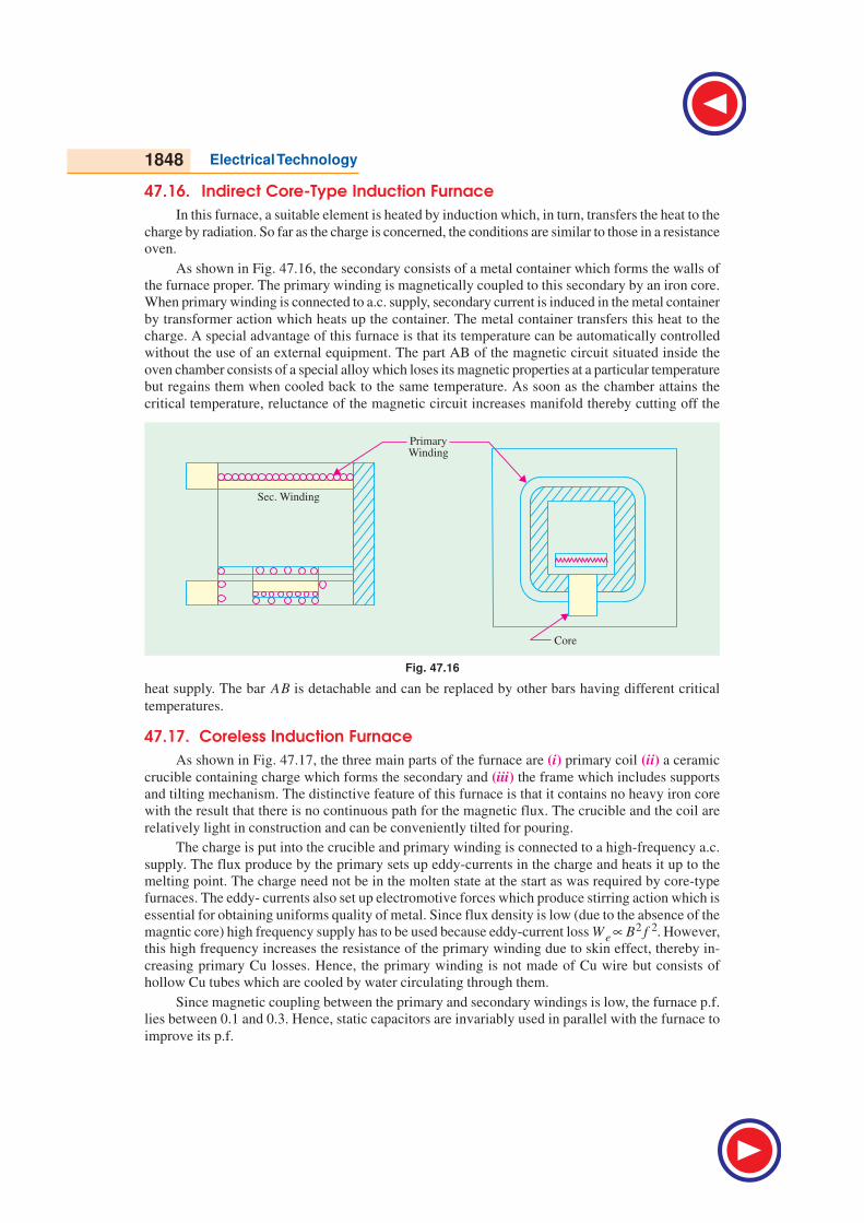
47.16. Indirect Core-Type Induction Furnace
In this furnace, a suitable element is heated by induction which, in turn, transfers the heat to the
charge by radiation. So far as the charge is concerned, the conditions are similar to those in a resistance
oven.
As shown in Fig. 47.16, the secondary consists of a metal container which forms the walls of
the furnace proper. The primary winding is magnetically coupled to this secondary by an iron core.
When primary winding is connected to a.c. supply, secondary current is induced in the metal container
by transformer action which heats up the container. The metal container transfers this heat to the
charge. A special advantage of this furnace is that its temperature can be automatically controlled
without the use of an external equipment. The part AB of the magnetic circuit situated inside the
oven chamber consists of a special alloy which loses its magnetic properties at a particular temperature
but regains them when cooled back to the same temperature. As soon as the chamber attains the
critical temperature, reluctance of the magnetic circuit increases manifold thereby cutting off the
Fig. 47.16
heat supply. The bar AB is detachable and can be replaced by other bars having different critical
temperatures.
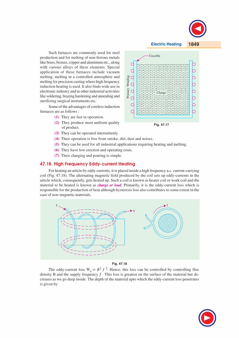
47.17. Coreless Induction Furnace
As shown in Fig. 47.17, the three main parts of the furnace are (i) primary coil (ii) a ceramic
crucible containing charge which forms the secondary and (iii) the frame which includes supports
and tilting mechanism. The distinctive feature of this furnace is that it contains no heavy iron core
with the result that there is no continuous path for the magnetic flux. The crucible and the coil are
relatively light in construction and can be conveniently tilted for pouring.
The charge is put into the crucible and primary winding is connected to a high-frequency a.c.
supply. The flux produce by the primary sets up eddy-currents in the charge and heats it up to the
melting point. The charge need not be in the molten state at the start as was required by core-type
furnaces. The eddy- currents also set up electromotive forces which produce stirring action which is
essential for obtaining uniforms quality of metal. Since flux density is low (due to the absence of the
magntic core) high frequency supply has to be used because eddy-current loss We ∝ B2 f 2. However,
this high frequency increases the resistance of the primary winding due to skin effect, thereby in-
creasing primary Cu losses. Hence, the primary winding is not made of Cu wire but consists of
hollow Cu tubes which are cooled by water circulating through them.
Since magnetic coupling between the primary and secondary windings is low, the furnace p.f.
lies between 0.1 and 0.3. Hence, static capacitors are invariably used in parallel with the furnace to
improve its p.f.
Electric Heating 1849
Such furnaces are commonly used for steel
production and for melting of non-ferrous metals
like brass, bronze, copper and aluminum etc., along
with various alloys of these elements. Special
application of these furnaces include vacuum
melting, melting in a controlled atmosphere and
melting for precision casting where high frequency
induction heating is used. It also finds wide use in
electronic industry and in other industrial activities
like soldering, brazing hardening and annealing and
sterilizing surgical instruments etc.
Some of the advantages of coreless induction
furnaces are as follows :
(1) They are fast in operation.
(2) They produce most uniform quality
of product.
(3) They can be operated intermittenly.
(4) Their operation is free from smoke, dirt, dust and noises.
(5) They can be used for all industrial applications requiring heating and melting.
(6) They have low erection and operating costs.
(7) Their charging and pouring is simple.
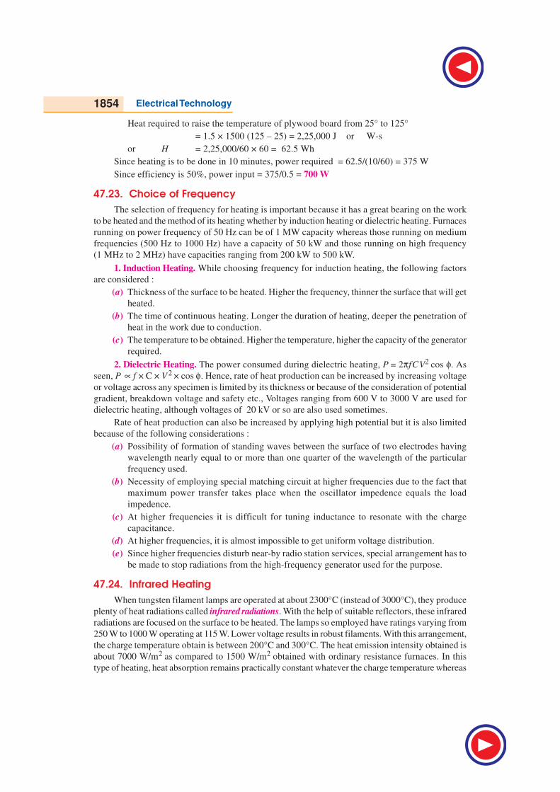
47.18. High Frequency Eddy-current Heating
For heating an article by eddy-currents, it is placed inside a high frequency a.c. current-carrying
coil (Fig. 47.18). The alternating magnetic field produced by the coil sets up eddy-currents in the
article which, consequently, gets heated up. Such a coil is known as heater coil or work coil and the
material to be heated is known as charge or load. Primarily, it is the eddy-current loss which is
responsible for the production of heat although hysteresis loss also contributes to some extent in the
case of non-magnetic materials.
Fig. 47.18
The eddy-current loss We ∝ B2 ƒ
2. Hence, this loss can be controlled by controlling flux
density B and the supply frequency ƒ. This loss is greatest on the surface of the material but de-
creases as we go deep inside. The depth of the material upto which the eddy-current loss penetrates
is given by
Fig. 47.17

1850 Electrical Technology
91 10
2 .r
df
ρπ µ
×=
where ρ = resistivity of the molten metal
f = supply frequency
µr = relative permeability of the charge
Advantages of Eddy-current Heating
(1) There is negligible wastage of heat because
the heat is produced in the body to be heated.
(2) It can take place in vacuum or other special
environs where other types of heating are not
possible.
(3) Heat can be made to penetrate any depth of
the body by selecting proper supply frequently.
Applications of Eddy-current Heating
(1) Surface Hardening. The bar whose surface is to be hardened by heat treatment is placed
within the working coil which is connected to an a.c. supply of high frequency. The depth upto
which the surface is to be hardened can be obtained by the proper selection of frequency of the coil
current. After a few seconds, when surface has reached the proper temperature, a.c. supply is cut off
and the bar is at once dipped in water.
(2) Annealing. Normally, annealing process takes long time resulting in scaling of the metal
which is undesirable. However, in eddy-current heating, time taken is much less so that no scale
formation takes place.
(3) Soldering. Eddy-current heating is economical for precise high-temperature soldering where
silver, copper and their alloys are used as solders.
Example. 47.6. Determine the efficiency of a high-frequency induction furnace which takes
10 minutes to melt 2 kg of a aluminium initially at a temperature of 20°C. The power drawn by the
furnace is 5 kW, specific heat of aluminium = 0.212, melting point of alumimium = 660° C and
latent heat of fusion of alumimium. = 77 kcal/kg.
Solution. Heat required to melt aluminium = 2 × 77 = 154 kcal
Heat required to raise the temperature of aluminium from 20°C to 660°C
= 2 × 0.212 × (660 – 20) = 2 × 0.212 × 640 = 271.4 kcal
Total heat required = 154 + 271.4 = 425.4 kcal
Heat required per hour = 425.4 × 60/10 = 2552.4 kcal
Power delivered to aluminium = 2552.4/860 = 2.96 kW
∴ efficiency = output/input = 2.97/5 = 0.594 or 59.4%
Example 47.7. A low-frequency induction furnace has a secondary voltage of 20V and takes
600 kW at 0.6 p.f. when the hearth is full. If the secondary voltage is kept constant, determine the
power absorbed and the p.f. when the hearth is half-full. Assume that the resistance of the secondary
circuit is doubled but the reactance remains the same.
Solution. Secondary current = 600 × 103/20 × 0.6 = 5 × 10⁴ A
If this current is taken as the reference quantity, then secondary voltage is
V2 = 20(0.6 + j 0.8) = (12 + j16)V
Hence, secondary impedence, Z2 = (12 + j 16)/5 × 104 = (2.4 + j 3.2) × 10 – 4 ohm
Eddy Current Heater

Electric Heating 1851
Now, if the secondary resistance is double, then total impedence when the hearth is half-full is
= Z2 = (4.8 + j3.2) × 10 – 4 ohm
Now, secondary current I 2 = 20/(4.8 + j3.2) × 10 –4
= 20/5.77 ∠ 33.7° × 104 = 3.466 ∠ –33.7° × 104 A
Now p.f. = cos 33.7° = 0.832
Hence, power absorbed = 20 × 3.466 × 104 × 0.832 × 10 – 3 = 580 kW
Example 47.8. Estimate the energy required to melt 0.5 tonne of brass in a single-phase
induction furnace. If the melt is to be carried out in 0.5 hour, what must be the average power input
to the furnace?
Specific heat of brass = 0.094
Latent heat of fusion of brass = 30 kilocal/kg
Melting point of brass = 920°C
Furnace efficiency = 60.2%
The temperature of the cold charge may be taken as 20°C
Solution. Total amount of heat required to melt 0.5 kg of brass.
= (0.5 × 1000) × 39 + 500 × 0.094 × (920 — 20)
= 61,800 kcal = 61,800/860 = 71.86 kWh
Total furnace input = 71.86/0.602 = 119.4 kWh
Example 47.9. A low-frequency induction furnace whose secondary voltage is maintained
constant at 10 V, takes 400 kW at 0.6 p.f. when the hearth is full. Assuming the resistance of the
secondary circuit to vary inversely as the height of the charge and reactance to remain constant,
find the height upto which the hearth should be filled to obtain maximum heat.
(Utili. of Elect. Power and Traction, Gorakhpur Univ.)
Solution. Secondary current I2 = P/V2 cos φ= 400 × 103/10 × 0.6 = 6.667 × 10⁴ A
Impedence of the secondary circuit when hearth is full
Z2 = V2 /I2 = 10/6.667 × 104 =1.5 × 10⁻⁴ ΩSecondary resistance when hearth is full, R2 =Z2 cos φ
= 1.5 × 10–4 × 0.6 = 0.9 × 10⁻⁴ ΩReactance of the secondary circuit, X 2 = Z2 sin φ
= 1.5 × 10–4 × 0.8 = 1.2 × 10⁻⁴ ΩIn the second, let the height of the charge be x times of the full hearth i.e. h = xH
Since resistance varies inversely as the height of the charge
= R2 = R2/x = 0.9 × 10⁻⁴/x ΩPower drawn and hence heat produced will be maximum where secondary resistance equals its
reactance.
∴ 0.9 × 10⁻⁴/x = 1.2 × 10⁻⁴ or x = 3/4
Hence, maximum heat would be produced in the charge when its height is three-fourth the
height of the hearth.
47.19. Dielectric Heating
It is also called high-frequency capacitative heating and is used for heating insulators like
wood, plastics and ceramics etc. which cannot be heated easily and uniformly by other methods. The
supply frequency required for dielectric heating is between 10-50 MHz and the applied voltage is
upto 20 kV. The overall efficiency of dielectric heating is about 50%.

1852 Electrical Technology
47.20. Dielectric Loss47.20. Dielectric Loss47.20. Dielectric Loss47.20. Dielectric Loss47.20. Dielectric Loss
When a practical capacitor is connected across an a.c. supply, it draws a current which leads
the voltage by an angle φ, which is a little less than 90° or falls short of 90° by an angle δ. It means
that there is a certain component of the current which is in phase with the voltage and hence pro-
duces some loss called dielectric loss. At the normal supply frequency of 50 Hz, this loss is negligi-
bly small but at higher frequencies of 50 MHz or so, this loss becomes so large that it is sufficient to
heat the dielectric in which it takes place. The insulating material to be heated is placed between two
conducting plates in order to form a parallel-plate capacitor as shown in Fig. 47.19 (a).
Fig. 47.19
Fig. 47.19 (b) shows the equivalent circuit of the capacitor and Fig. 47.19 (c) gives its vector
diagram.
Power drawn from supply = VI cos φNow, Ic = I =V/Xc = 2πf CV
∴ P = V(2πfCV ) cos φ = 2πfCV 2 cos φNow, φ = (90 – δ), cos φ = cos (90 – δ) = sin δ = tan δ = δwhere δ is very small and is expressed in radians.
P = 2πfCV 2δ watts
Here, C = 0 r
A
d∈ ∈ where d is the thickness and A is the surface area of the dielectric slab.
This power is converted into heat. Since for a given insulator material, C and δ are constant,
the dielectric loss is directly proportional to V 2 f. That is why high-frequency voltage is used in
dielectric heating. Generally, a.c. voltage of about 20 kV at a frequency of 10-30 MHz is used.
47.21. Advantages of Dielectric Heating47.21. Advantages of Dielectric Heating47.21. Advantages of Dielectric Heating47.21. Advantages of Dielectric Heating47.21. Advantages of Dielectric Heating
1. Since heat is generated within the dielectric medium itself, it results in uniform heating.
2. Heating becomes faster with increasing frequency.
3. It is the only method for heating bad conductors of heat.
4. Heating is fastest in this method of heating.
5. Since no naked flame appears in the process, inflammable articles like plastics and wooden
products etc., can be heated safely.
6. Heating can be stopped immediately as and when desired.

Electric Heating 1853
47.22. Applications of Dielectric Heating47.22. Applications of Dielectric Heating47.22. Applications of Dielectric Heating47.22. Applications of Dielectric Heating47.22. Applications of Dielectric Heating
Since cost of dielectric heating is very
high, it is employed where other methods are
not possible or are too slow. Some of the
applications of dielectric heating are as under :
1. For gluing of multilayer plywood
boards.
2. For baking of sand cores which are
used in the moulding process.
3. For preheating of plastic compounds
before sending them to the moulding
section.
4. For drying of tobacco after glycerine has been mixed with it for making cigarattes.
5. For baking of biscuits and cakes etc. in bakeries with the help of automatic machines.
6. For electronic sewing of plastic garments like raincoats etc. with the help of cold rollers fed
with high-frequency supply.
7. For dehydration of food which is then sealed in air-tight containers.
8. For removal of moistures from oil emulsions.
9. In diathermy for relieving pain in different parts of the human body.
10. For quick drying of glue used for book binding purposes.
Example. 47.10. A slab of insulating material 150 cm2 in area and 1 cm thick is to be heated
by dielectric heating. The power required is 400 W at 30 MHz. Material has relative permittivity of
5 and p.f. of 0.05. Determine the necessary voltage. Absolute permittivity = 8.854 × 10 – 12 F/m.
(Utilisation of Elect. Energy, Punjab Univ.)
Solution. P = 400 W, p.f. = 0.05, f = 30 × 106 Hz
C = ∈0∈r A/d = 8.854 × 10–12 × 5 × 150 × 10–4/1 × 10–2 = 66.4 × 10 – 12 F
Now, P = 2πf CV 2 cosφ or 400 = 2π × 30 × 106 × 66.4 × 10 – 12 × V2 × 0.05 or V = 800 V
Example. 47.11. An insulating material 2 cm thick and 200 cm2 in area is to be heated by
dielectric heating. The material has relative permitivity of 5 and power factor of 0.05. Power
required is 400 W and frequency of 40 MHz is to be used. Determine the necessary voltage and the
current that will flow through the material. If the voltage were to be limited to 700 V, what will be
the frequency to get the same loss? (A.M.I.E. Sec. B)
Solution. C = 8.854 × 10–12 × 5 × 200 × 10–4/2 × 10–2 = 44.27 × 10⁻¹² F
2 6 122 cos 400 / 2 40 10 44.27 10 0.05P fCVπ π −= φ × × × × ×or V= = 848 V
Current flowing through the material,
I = P/V cos φ = 400/848 × 0.05 = 9.48 A
Heat produced ∝ V2 f
∴ V22 f2 = V1
2 f1 or f2 = f1 (V1/V2)2 = 40 × 106 (848/700)2 = 58.7 MHz
Example 47.12. A plywood board of 0.5 × 0.25 × 0.02 metre is to be heated from 25 to 125°C
in 10 minutes by dielectric heating employing a frequency of 30 MHz. Determine the power
required in this heating process. Assume specific heat of wood 1500/J/kg/°C; weight of wood
600 kg/m3 and efficiency of process 50%. (Utilisation of Traction, B.H.U.)
Solution. Volume of plywood to be heated = 0.5 × 0.25 × 0.02 = 0.0025 m3
Weight of plywood = 0.0025 × 600 = 1.5 kg
Dielectric heating
1854 Electrical Technology
Heat required to raise the temperature of plywood board from 25° to 125°
= 1.5 × 1500 (125 – 25) = 2,25,000 J or W-s
or H = 2,25,000/60 × 60 = 62.5 Wh
Since heating is to be done in 10 minutes, power required = 62.5/(10/60) = 375 W
Since efficiency is 50%, power input = 375/0.5 = 700 W
47.23. Choice of Frequency
The selection of frequency for heating is important because it has a great bearing on the work
to be heated and the method of its heating whether by induction heating or dielectric heating. Furnaces
running on power frequency of 50 Hz can be of 1 MW capacity whereas those running on medium
frequencies (500 Hz to 1000 Hz) have a capacity of 50 kW and those running on high frequency
(1 MHz to 2 MHz) have capacities ranging from 200 kW to 500 kW.
1. Induction Heating. While choosing frequency for induction heating, the following factors
are considered :
(a) Thickness of the surface to be heated. Higher the frequency, thinner the surface that will get
heated.
(b) The time of continuous heating. Longer the duration of heating, deeper the penetration of
heat in the work due to conduction.
(c) The temperature to be obtained. Higher the temperature, higher the capacity of the generator
required.
2. Dielectric Heating. The power consumed during dielectric heating, P = 2πfCV2 cos φ. As
seen, P ∝ f × C × V2 × cos φ. Hence, rate of heat production can be increased by increasing voltage
or voltage across any specimen is limited by its thickness or because of the consideration of potential
gradient, breakdown voltage and safety etc., Voltages ranging from 600 V to 3000 V are used for
dielectric heating, although voltages of 20 kV or so are also used sometimes.
Rate of heat production can also be increased by applying high potential but it is also limited
because of the following considerations :
(a) Possibility of formation of standing waves between the surface of two electrodes having
wavelength nearly equal to or more than one quarter of the wavelength of the particular
frequency used.
(b) Necessity of employing special matching circuit at higher frequencies due to the fact that
maximum power transfer takes place when the oscillator impedence equals the load
impedence.
(c) At higher frequencies it is difficult for tuning inductance to resonate with the charge
capacitance.
(d) At higher frequencies, it is almost impossible to get uniform voltage distribution.
(e) Since higher frequencies disturb near-by radio station services, special arrangement has to
be made to stop radiations from the high-frequency generator used for the purpose.
47.24. Infrared Heating
When tungsten filament lamps are operated at about 2300°C (instead of 3000°C), they produce
plenty of heat radiations called infrared radiations. With the help of suitable reflectors, these infrared
radiations are focused on the surface to be heated. The lamps so employed have ratings varying from
250 W to 1000 W operating at 115 W. Lower voltage results in robust filaments. With this arrangement,
the charge temperature obtain is between 200°C and 300°C. The heat emission intensity obtained is
about 7000 W/m2 as compared to 1500 W/m2 obtained with ordinary resistance furnaces. In this
type of heating, heat absorption remains practically constant whatever the charge temperature whereas
Electric Heating 1855
it falls rapidly as the temperature of charge rises in the ordinary resistance furnace.
Infrared heating is used for paint drying and for drying foundary moulds, for low temperature
heating of plastics and for various dehydration and other processes.
Tutorial Problem No. 47.1
1. A slab of insulating material 150 cm2 in area and 1 cm. thick is to be heated by dielectric heating.
The power required is 400W at 30 MHz. Material has permitivity of 5 and p.f. 0.05. Determine thevoltage necessary. Absolute permittivity = 8.854 × 10⁻¹² F/m.
[800 V] (Utilisation of Elect. Energy, Punjab Univ.)
2. A 20-kW, 1-phase, 220-V resistance oven employs circular nickel chrome wire for its heatingelements. If the wire temperature is not to exceed 1107° C and the temperature of the charge is tobe 500°C, calculate the length and size of wire required. Assume a radiating efficiency of 0.6 andthe specific resistance of nickel chrome as 100 × 10–6 Ω cm and emissivity 0.9.
[ l =17.1 m, d = 0.3 cm] (Utilisation of Elect. Power, A.M.I.E.)
3. An electric toaster consists of two resistance elements each of 190 ohm. Calculate the power drawnfrom 250 V a.c. single-phase supply, when the elements are connected in (i) parallel and (ii) series.
[(i) 658 W (ii) 164.5 W]
4. A 15-kW, 220-V, single-phase resistance oven employs nickel-chrome wire for its heating ele-ments. If the wire temperature is not to exceed 1,000°C and the temperature of the charge is to be600°C, calculate the diameter and length of the wire. Assume radiating efficiency to be 0.6 and
emissivity as 0.9. For nickel chrome resistivity is 1.016 × 10⁻⁶ Ω–m. [3.11 mm, 24.24 m]
(Utili. of Elect. Power, A.M.I.E. Sec. B)
5. A 30-kW, 3-phase, 400-V resistance oven is to employ nickel-chrome strip 0.025 cm thick for the
3-phase star-connected heating elements. If the wire temperature is to be 1100°C and that of charge
is to be 700°C, estimate a suitable width for the strip. Assume radiating efficiency as 0.6 and
emissivity as 0.90. The specific resistance of the nichromealloy is 1.03 × 10⁻⁶ Ω–m. State any
assumptions made. [6.86 mm] (Utili. of Elect. Power, A.M.I.E. Sec. B.)
6. Estimate the efficiency of a high-frequency induction furnace which takes 10 minutes to melt 1.8
kg of a aluminium, the input to the furnace being 5 kW and initial temperature 15°C. Given :
Specific heat of aluminium = 880 J/kg/°C
Melting point of aluminium = 660°C
Latent heat of fusion of aluminium = 32 kJ/kg and 1J = 2.78 × 10⁻⁷ kWh.
[36 %] (Elect. Drives and Util. of Elect. Energy, Punjab Univ.)
7. A 3-phase electric arc furnace has the following data :
Current drawn = 5,000 A ; Arc voltage = 50 V
Resistance of transformer referred to primary =0.002 ΩResistance of transformer referred to secondary=0.004 Ω(i) Calculate the power factor and kW drawn from the supply.
(ii) If the overall efficiency of furnace is 65%, find the time required to melt 2 tonnes of steel when
latent heat of steel = 8.89 kcal/kg. Specific heat of steel = 0.12, melting point of steel = 1370°C
and initial temperature of steel = 20°C.
[(i) 0.9847; 900 kW, (ii) 40 min. 46 s.] (Utili. of Elect. Power, A.M.I.E. Sec. B.)
8. Dielectric heating is to be employed to heat a slab of insulating material 20 mm thick and 1530
mm2 in area. Power required is 200 W and a frequency of 3 MHz is to be used. The material has a
permitivity of 5 and p.f. of 0.05. Determine the voltage necessary and the current which will flow
through the material. [8000 V ; 0.5 A] (Elect. Drives and Utili of Elect. Energy, Punjab Univ.)
9. What are the advantages of electrically produced heat? What are the properties to be possessed by
the element used in resistance oven? (J.N. University, Hyderabad, November 2003)
10. A 20 kW single-phase, 220 V resistance oven employs circular nichrome wire for its heating element,
if the wire temperature is not to exceed 1227o and the temperature of the charge is to be 427oC,
calculate the size and length of the wire required. Assume emissivity = 0.9, radiating efficiency =
0.6 and specific resistance of wire = 1.09 × 10⁻⁶Ω–m.
(J.N. University, Hyderabad, November 2003)
1856 Electrical Technology
11. Discuss the various modes of heat dissipation. (J.N. University, Hyderabad, November 2003)
12. Explain in brief how heating is done in the following cases?
(i) Resistance heating, (ii) Induction heating, (iii) Dielectric heating.
(J.N. University, Hyderabad, November 2003)
13. 90 Kg of tin is to smelt during an hour in smelting furnace. Determine the suitable rating of teh
furnace, if melting temperature = 230oC, specific heat = 0.055, latent heat of liquidification is 13.3
Kcal/kg. Take the initial temperature of the metal as 35oC.
(J.N. University, Hyderabad, November 2003)
14. Explain the principle of Induction heating, What are the applications ofinduction heating.
(J.N. University, Hyderabad, November 2003)
15. With a neat sketch explain the working principle of coreless type induction furnace.
(J.N. University, Hyderabad, November 2003)
16. Explain with a neat sketch the principle of coreless type induction furnace.
(J.N. University, Hyderabad, November 2003)
17. 100 kg of tin is to smelt in one hour in a smelting furnance. Determine the suitable rating of furnace
if smelting temperature of tin is 235oC; specific heat is 0.055, latent heat of liquidification 13.3
Kcal/kg. Take initial temperature of metal as 35oC.(J.N. University, Hyderabad, November 2003)
18. A low frequency Induction Furnace whose secondary voltage is maintained constant at 12 Volts
takes 300 Kw at 0.65 p.f. when the head of the charge and reactance to remain constant, find the
height upto which the hearth should be filled to obtain maximum heat.
(J.N. University, Hyderabad, November 2003)
19. Give relative advantages and disadvantages of direct and indirect electric arc furnances.
(J.N. University, Hyderabad, April 2003)
20. An electric arc furnace consuming 5 KW takes 15 minutes to just melt 1.5 Kgs of aluminium, the
initial temperature being 15oC. Find the efficiency of the furnace. Specific heat of aluminium is
0.212, melting point 658oC and latent heat of fusion is 76.8 Cal per gram.
(J.N. University, Hyderabad, April 2003)
21. What are the causes of failure of heating elements? (J.N. University, Hyderabad, April 2003)
22. Six resistances each of 40ohms are used as heating elements in furnace. Find the power of the
furnace for various connections to a three phase 230 V supply.
(J.N. University, Hyderabad, April 2003)
23. What are different methods of heat transfer Explain in brief ?
(J.N. University, Hyderabad, April 2003)
24. What are the advantages of radiant heating ? (J.N. University, Hyderabad, April 2003)
25. Describe various types of electric heating equipment. (J.N. University, Hyderabad, April 2003)
26. What are the causes of failure of heating elements? (J.N. University, Hyderabad, April 2003)
27. Six resistances each of 40 ohms are used as heating elements in furnace. Find the power of the
furnace for various connections to a three phase 230 V supply.
(J.N. University, Hyderabad, April 2003)
28. Explain why very high frequencies should not be used for dielectric hearing.
(J.N. University, Hyderabad, December 2002/January 2003)
29. A wooden board 30 cms × 15 cms × 2 cms is to be heated from 20oC to 180oC in 10 minutes by
dielectric heating using 40 MHz supply. Specific heat of wood 0.35 and density 0.55 gm/cc. εr = 5
and p.f. 0.05. Estimate the voltage across the specimen and current during heating. Assume loss of
energy by conduction, convection and radiation as 10%.
(J.N. University, Hyderabad, December 2002/January 2003)
30. Write short Notes on The Ajax-yatt furnace.
(J.N. University, Hyderabad, December 2002/January 2003)
31. Discuss the different methods of electric heating and their relative merits
(J.N. University, Hyderabad, December 2002/January 2003)
32. Dielectric heating is to be employed to heat a slab of insulating meterial of 20 mm thick and 1500
mm2 in area. The power required is 200 watts at a frequency of 30 MHz. The material has a
permittivity of 5 and a power factor of 0.05. Determine the voltage necessary and the current which
flows through the material. (J.N. University, Hyderabad, December 2002/January 2003)
Electric Heating 1857
33. State the advantages of electric heating.
(J.N. University, Hyderabad, December 2002/January 2003)
34. Brifely explain the different methods of electric heating.
(J.N. University, Hyderabad, December 2002/January 2003)
35. Estimate the energy required to melt 500 kg of brass in a single phase Ajax-wyatt furnace.Ifthe
melting is to be carried out in 3/4 hour, what must be the avarage power input to the furnace.
(J.N. University, Hyderabad, December 2002/January 2003)
OBJECTIVE TESTS – 47
1. As compared to other methods of heating
using gas and coal etc, electric heating is far
superior because of its.
(a) cleanliness
(b) ease of control
(c) higher efficiency
(d) all of the above.
2. Magnetic materials are heated with the help
of
(a) hysteresis loss (b) electric arc
(c) electric current (d) radiation.
3. In the indirect resistance heating method, heat
is delivered to the charge
(a) direcly (b) by radiation
(c) by convection (d) both (b) and (c).
4. The main requirements of a good heating
element used in a resistance furnaces are
(a) high resistivity
(b) high melting-temperature
(c) positive resistance-temperature
coefficient
(d) all of the above.
5. Electric ovens using heating elements of
........................... can produce tempera- tures
up to 3000°C
(a) nickel (b) graphite
(c) chromium (d) iron.
6. The temperature of resistance furnaces can be
controlled by changing the
(a) applied voltage
(b) number of heating elements
(c) circuit configuration
(d) all of the above.
7. Which of the following heating method is
based on the transformer principle ?
(a) resistance heating
(b) eddy-current heating
(c) induction heating
(d) dielectric heating.
8. When graphite electrodes are used in arc
furnaces, the temperature obtained is in the
range of ...............................degree centi-
grade.
(a) 3000-3500 (b) 2500-3000
(c) 2000-2500 (d) 1500-2000
9. Which of the following furnace suffers from
pinch effect?
(a) resistance furnace
(b) core type induction furnace
(c) coreless induction furnace
(d) vertical core type induction furnace.
10. Which of the following induction furnace has
the lowest power factor?
(a) vertical core type
(b) indirect core type
(c) coreless type
(d) core type.
11. The coreless induction furnace uses high-
frequency electric supply in order to
obtain high
(a) flux density
(b) eddy-current loss
(c) primary resistance
(d) power factor.
12. Inflammable articles like plastic and wooden
products etc, can be safely heated by
using.................... heating.
(a) eddy-current (b) dielectric
(c) induction (d) resistance
13. Which of the following is an advantages of
heating by electricity?
(a) Quicker operation
(b) Higher efficiency
(c) Absence of flue gases
(d) All of the above
14. ...... has the highest value of thermal
conductivity.
(a) Copper (b) Aluminium
(c) Brass (d) Steel
15. Which of the following heating methods has
maximum power factor?
(a) Arc heating
(b) Dielectric heating
(c) Induction heating
(d) Resistance heating
1858 Electrical Technology
16. ...... method has leading power factor
(a) Resistance heating
(b) Dielectric heating
(c) Arc heating
(d) Induction heating
17. ...... is used for heating non-conducting
meterials.
(a) Eddy current heating
(b) Arc heating
(c) Induction heating
(d) Dielectric heating
18. Which of the following methods of heating is
not dependent on the frequency of supply?
(a) Induction heating
(b) Dielectric heating
(c) Electric resistance heating
(d) All of the above
19. When a body reflects entire radiation incident
on it, then it is known as
(a) white body (b) grey body
(c) black body (d) transparent body
20. For the transmission of heat from one body to
another
(a) temperature of the two bodies must be
different
(b) both bodies must be solids
(c) both bodies must be in contact
(d) at least one of the bodies must have some
source of heating
21. Heat transfer by condition will not occur when
(a) bodies are kept in vacuum
(b) bodies are immersed in water
(c) bodies are exposed to thermal radiations
(d) temperatures of the two bodies are
identical
22. A perfect black body is one that
(a) transmits all incident radiations
(b) absorbs all incident radions
(c) reflects all incident radiations
(d) absorbs, reflects and transmits all incident
radiations
23. Heat is transferred simultaneously by
condition, convection and radiation
(a) inside boiler furnaces
(b) during melting of ice
(c) through the surface of the insulted pipe
carring steam
(d) from refrigerator coils to freezer of a
refrigerator
24. The process of heat transfer during the re-entry
of satellites and missiles, at very high speeds,
into earth’s atmosphere is known as
(a) ablation
(b) radiation
(c) viscous dissipation
(d) irradiation
25. Which of the following has the highest value
of thermal conductivity?
(a) Water (b) Steam
(c) Solid ice (d) Melting ice
26. Induction heating process is based on which
of the following principles?
(a) Thermal ion release principle
(b) Nucleate heating principle
(c) Resistance heating principle
(d) Electro-magnetic induction principle
27. Which of the following insulating materials is
suitable for low temperature applications?
(a) Asbestos paper
(b) Diatomaceous earth
(c) 80 percent magnesia
(d) Cork
28. A non-dimensional number generally
associated with natural convection heat transfer
is
(a) Prandtl number
(b) Grash off number
(c) Pecelet number
(d) Nusselt number
29. The temperature inside a furnace is usually
measured by which of the following?
(a) Optical pyrometer
(b) Mercury thermometer
(c) Alcohol thermometer
(d) Any of the above
30. Which of the following will happen if the
thickness of refractory wall of furnace is
increased?
(a) Heat loss through furnace wall will
increase
(b) Temperature inside the furnace will fall
(c) Temperature on the outer surface of
furnace walls will drop
(d) Energy consumption will increase
31. The material of the heating element for a
furnace should have
(a) lower melting point
(b) higher temperature co-efficient
(c) high specific resistance
(d) all of the above
32. In a resistance furnace the atmosphere is .......
(a) oxidising (b) deoxidising
(c) reducing (d) neutral
33. By which of the following methods the
temperature inside a resistance furnance can
be varied?
(a) By disconnecting some of the heating
elements
(b) By varying the operating voltage
(c) By verying the current through heating
elements
(d) By any of the above method

Electric Heating 1859
34. In induction heating ...... is abnormally high.
(a) phase angle (b) frequency
(c) current (d) voltage
35. By the use of which of the following high
frequency power supplyv for induction
furnaces can be obtained?
(a) Coreless transformers
(b) Current transformers
(c) Motor-generator set
(d) Multi-phase transformer
36. Induction furnaces are employed for which of
the following?
(a) Heat treatment of castings
(b) Heating of insulators
(c) Melting aluminium
(d) None of the above
37. In an electric room heat convector the method
of heating used is
(a) arc heating
(b) resistance heating
(c) induction heating
(d) dielectric heating
38. In a domestic cake baking oven the
temperature is controlled by
(a) voltage variation
(b) thermostat
(c) auto-transformer
(d) series-parallel operation
39. In an electric press mica is used
(a) as an insulator
(b) as a device for power factor improvement
(c) for dielectric heating
(d) for induction heating
40. Induction heating takes place in which of the
following?
(a) Insulating materials
(b) Conducting materials which are magnetic
(c) Conducting materialswhich are non-
magnetic
(d) Conducting materials which may or may
not be magnetic
41. For heating element high resistivity material
is chosen to
(a) reduce the length of heating element
(b) increase the life of the heating element
(c) reduce the effect of oxidation
(d) produce large amount of heat
42. In resistance heating highest working
temperature is obtained from heating elements
made of ........
(a) nickel copper (b) nichrome
(c) silicon carbide (d) silver
43. For intermittent work which of the following
furnaces is suitable?
(a) Indirect arc furnace
(b) Core less furnace
(c) Either of the above
(d) None of the above
44. Due to which of the following reasons it is
desirable to have short arc length?
(a) To achieve better heating
(b) To increase the life of roof refractory
(c) To have better stirring action
(d) To reduce problem of oxidation
(e) All of the above
45. In the indirect resistance heating method,
maximum heat-transfer takes place by
(a) radiation (b) convection
(c) conduction (d) any of the above
46. Property of low temperature co-efficient of
heating element is desired due to which of the
following reasons?
(a) To avoid initial rush of current
(b) To avoid change in kW rating with
temperature
(c) Both (a) and (b)
(d) Either (a) or (b)
47. Which of the following methods is used to
control temperature in resistance furnaces?
(a) Variation of resistance
(b) Variation of voltage
(c) Periodical switching on and off of the
supply
(d) All of the above methods
48. It is desirable to operate the arc furnace at
power factor of
(a) zero (b) 0.707 lagging
(c) unity (d) 0.707 leading
49. Radiations from a black body are proportional
to
(a) T (b) T2
(c) T3 (d) T4
50. In arc furnace the function of choke is
(a) to stabilize the arc
(b) to improve power factor
(c) to reduce severity of the surge
(d) none of the above
51. Ajax Wyatt furnace is started when
(a) it is filled below core level
(b) it is filled above core level
(c) it is fully empty
(d) none of the above
52. In electric press, mica is used because it is .......
conductor of heat but/and ....... conductor of
electricity.
(a) bad, good (b) bad, bad
(c) good, bad (d) good, good
53. Resistance variation method of temperature
control is done by connecting resistance
elements in
1860 Electrical Technology
(a) series
(b) parallel
(c) series-parallel connections
(d) star-delta connections
(e) all of the above ways
54. Hysteresis loss and eddy current loss are used
in
(a) induction heating of steel
(b) dielectric heating
(c) induction heating of brass
(d) resistance heating
55. In heating the ferromagnetic material by
induction heating, heat is produced due to
(a) induced current flow through the charge
(b) hysteresis loss taking place below curie
temperature
(c) due to hysteresis loss as well as eddy
current loss taking place in the charge
(d) one of the above factors
56. Radiant heating is used for which of the
following?
(a) Annealing of metals
(b) Melting of ferrous metals
(c) Heating of liquids in electric kettle
(d) Drying of paints and varnishes
57. Which of the following devices is necessarily
required for automatic temperature control in
a furnace?
(a) Thermostat
(b) Thermocouple
(c) auto-transformer
(d) Heating elements of variable resistance
material
58. For radiant heating around 2250oC, the heating
elements are made of
(a) copper alloy (b) carbon
(c) tungsten alloy (d) stainless steel alloy
59. Which of the following is an advantage of eddy
current heating?
(a) The amount of heat generated can be
controlled accurately
(b) Heat at very high rate can be generated
(c) The area of the surface over which heat is
produced can be accurately controlled
(d) All of the above
60. The electrode of a direct arc furnace is made
of
(a) tungsten
(b) graphite
(c) silver
(d) copper
61. Direct arc furnaces have which of the following
power factors?
(a) Unity
(b) Low, lagging
(c) Low, leading
(d) Any of the above
62. In direct arc furnace, which of the following
has high value?
(a) Current
(b) Voltage
(c) Power factor
(d) All of the above
ANSWERS
1. (d) 2. (a) 3. (d) 4. (d) 5. (b) 6. (d) 7. (c)
8. (a) 9. (b) 10. (d) 11. (b) 12. (b) 13. (d) 14. (a)
15. (d) 16. (b) 17. (d) 18. (c) 19. (a) 20. (a) 21. (d)
22. (b) 23. (a) 24. (a) 25. (c) 26. (d) 27. (b) 28. (b)
29. (a) 30. (c) 31. (c) 32. (a) 33. (d) 34. (b) 35. (c)
36. (a) 37. (b) 38. (b) 39. (a) 40. (d) 41. (a) 42. (c)
43. (a) 44. (e) 45. (a) 46. (c) 47. (d) 48. (b) 49. (d)
50. (a) 51. (d) 52. (c) 53. (e) 54. (a) 55. (c) 56. (d)
57. (b) 58. (c) 59. (d) 60. (b) 61. (b) 62. (a)
GO To FIRST