CONTENTS 2 COMPARISON OF BLACK POINT TERMINAL …
106
LNG RECEIVING TERMINAL AND ASSOCIATED FACILITIES PART 3 –BLACK POINT EIA SECTION 2 – CONSIDERATION OF ALTERNATIVES CONTENTS 2 COMPARISON OF BLACK POINT TERMINAL ALTERNATIVES 1 2.1 CONSIDERATION OF DIFFERENT LAYOUTS AND DESIGN OPTIONS 1 2.2 CONSIDERATION OF ALTERNATIVE CONSTRUCTION METHODS 22 2.3 SELECTION OF PREFERRED SCENARIO 28 ANNEXES Annex 2 Comparison of Black Point Alternatives Annex 2-A Engineering Assessment Annex 2-B Environmental Assessment
Transcript of CONTENTS 2 COMPARISON OF BLACK POINT TERMINAL …

LNG RECEIVING TERMINAL AND ASSOCIATED FACILITIES PART 3 –BLACK POINT EIA SECTION 2 – CONSIDERATION OF ALTERNATIVES
CONTENTS
2 COMPARISON OF BLACK POINT TERMINAL ALTERNATIVES 1
2.1 CONSIDERATION OF DIFFERENT LAYOUTS AND DESIGN OPTIONS 1 2.2 CONSIDERATION OF ALTERNATIVE CONSTRUCTION METHODS 22 2.3 SELECTION OF PREFERRED SCENARIO 28
ANNEXES
Annex 2 Comparison of Black Point Alternatives Annex 2-A Engineering Assessment Annex 2-B Environmental Assessment

LNG RECEIVING TERMINAL AND ASSOCIATED FACILITIES PART 3 –BLACK POINT EIA SECTION 2 – CONSIDERATION OF ALTERNATIVES
0018180_EIA PART 3 S2 TEXT_V7.DOC 11 DEC 2006
1
2 COMPARISON OF BLACK POINT TERMINAL ALTERNATIVES
The following section presents a comparison of the alternatives for the Black Point terminal. The section has been divided into a discussion of the following:
• Consideration of Different Layouts and Design Options; and
• Consideration of Alternative Construction Methods.
Based on the above considerations, the Environmental Impact Assessment (EIA) of the preferred Black Point terminal scenario is presented in subsequent sections.
2.1 CONSIDERATION OF DIFFERENT LAYOUTS AND DESIGN OPTIONS
In accordance with Clause 3.6.4 of the EIA Study Brief (ESB-126/2005), this section presents considerations of the different layouts and design options that have been assessed as part of the overall assessment of alternatives for the Black Point terminal. The methodology, criteria and findings are presented.
The assessment was conducted to investigate the environmental considerations of each layout and design option and to examine the engineering aspects for each. The assessment thus considers both the difficulties of the construction and operation of each facility as well as the associated potential environmental impacts.
2.1.1 Layout Options
The basic requirements of a LNG receiving terminal in Hong Kong have been described in detail in Part 1 - Section 3. Justifications for Black Point being considered as one of two sites for a LNG receiving terminal in Hong Kong have been presented in Part 1 – Section 4.
Several terminal layout options on Black Point have been considered. As there is limited flat land at Black Point to accommodate the necessary infrastructure, the method of providing sufficient land, either by reclamation or excavation of the existing headland has been considered. In addition, due to the outline of the coastline, there are options for locating the LNG carrier berth. These provide differences in dredging requirements but similar approach and berthing issues.
Three layouts have been selected for further assessment in order to provide a comprehensive assessment of different layouts and design options. The layouts present, as best possible, a wide range of engineering options and subsequent environmental considerations for the construction and operation of the Black Point terminal. Each of the layouts has been prepared so that the

LNG RECEIVING TERMINAL AND ASSOCIATED FACILITIES PART 3 –BLACK POINT EIA SECTION 2 – CONSIDERATION OF ALTERNATIVES
0018180_EIA PART 3 S2 TEXT_V7.DOC 11 DEC 2006
2
distances between the facilities within the LNG terminal show broad compliance with EN1473. The three layouts are presented below in terms of the general design and construction methods.
Option 1 – Base Case
Layout Option 1 - Base Case is derived from a combination of reclamation and excavation (Figure 2.1). The purpose of this combination is to maintain a balance between the cut and fill quantities, and to create cost effective and sustainable site formation. The area of excavation for the site is limited to provide sufficient land area initially for two tanks to enable them to be founded directly on rock which will permit the use of pad/raft foundations thus negating the need for deep foundations. The steep rock face behind will also screen the two tanks from any visual sensitive receivers. A platform at a level of +6mPD will be formed by excavation into the existing hillside. Land will be reclaimed immediately to the northwest of the Black Point headland to accommodate the third tank and the terminal facilities.
The LNG carrier jetty will be located to the northwest of the reclaimed land. Although the jetty is close to the Urmston Road fairway, the presence of the headland provides protection from contact by passing traffic. It also has the advantage that the main components of the facility are screened from the public by the ridgeline of the Black Point headland.
Option 2 – Full Reclamation
Layout Option 2 - Full Reclamation is derived such that no excavation is undertaken in the Black Point peninsula (Figure 2.2). All the land needed for the three LNG tanks and terminal facilities will be provided by reclamation at the end of the Black Point peninsula. The platform level will be at +6mPD. The tanks will be located nearer to the existing hillside as the rock head is shallower which facilitates foundation construction. As in Option 1, the LNG carrier jetty will be located to the northwest of the reclaimed land.
Option 3 – Full Excavation
Layout Option 3 - Full Excavation would require no reclamation into the sea such that the required land is generated by excavation only into the Black Point headland. In order to create a platform of sufficient area at a level of +6mPD to house the three tanks and all the terminal facilities a cutting up to 30m in height will be required. By cutting into the headland the facility is expected to be more visible from views to the south.
The LNG carrier jetty will be located to the west of the Black Point site.
Engineering Works Criteria
In order to satisfy each of the terminal requirements described in Part 1 - Section 3, it is necessary to undertake site formation, dredging and reclamation

LNG RECEIVING TERMINAL AND ASSOCIATED FACILITIES PART 3 –BLACK POINT EIA SECTION 2 – CONSIDERATION OF ALTERNATIVES
0018180_EIA PART 3 S2 TEXT_V7.DOC 11 DEC 2006
3
works at each of the layout options at Black Point. A summary of the key engineering works criteria for each layout option are summarised in Table 2.1.
Table 2.1 Summary of Engineering Works Criteria (based on conceptual indicative site layouts)
Engineering Criteria Option 1 (Base Case)
Option 2 (Full Reclamation)
Option 3 (Full Excavation)
Site Area (ha)
32.0 31.5 35.0
Volume of Dredging for Reclamation (106m³)
0.63 0.65 0
Volume of Dredging for Approach Channel & Turning Basin (106m³)
2.49 2.49 1.40
Volume of Excavation Disposed (106m³)
0 0 14
Volume of Fill Imported (106m³)
1.90 3.43 0
Length of Natural Coastline Affected (m)
600 580 0
Length of Seawall (m)
1,120 1,160 0
Length of Trestle (m)
100 100 180
The layouts described above have been considered in terms of a technical comparison and assessment of the engineering works followed by a comparison of the potential for environmental impacts through construction and operation. Each of these assessments is presented below, followed by a summary of the overall findings. On the basis of these assessments, the preferred layout and design option for the Black Point terminal is identified.
2.1.2 Engineering Assessment
Overall Engineering Assessment Criteria
The key engineering assessment criteria have been established to enable a quantitative comparison of the three layout options to be scored and ranked in accordance with their relative merits and demerits. As each of these assessment criteria do not have an equivalent impact on the overall construction of the terminal facility, a relative importance factor has been applied to each as shown in Table 2.2.

LNG RECEIVING TERMINAL AND ASSOCIATED FACILITIES PART 3 –BLACK POINT EIA SECTION 2 – CONSIDERATION OF ALTERNATIVES
0018180_EIA PART 3 S2 TEXT_V7.DOC 11 DEC 2006
4
Table 2.2 Overall Engineering Assessment Criteria
Engineering Assessment Criterion Relative Importance Factor Construction of site formation works 0.30 Construction of site reclamation works 0.30 Construction of approach channel and turning basin 0.20 Marine navigation 0.10 Construction of facility foundations 0.10 Total 1.00
The rationale for the relative importance factor is given below.
• It was considered logical for the sum of the relative importance factors to add up to unity. In this manner each relative importance factor also directly represents the percentage importance to the whole process.
• The major engineering works for each of the layout options is considered to be the construction of the site formation and reclamation. These assessment criterions are, therefore, given an equally high relative importance factor of 30% each.
• The next major engineering works for the layout options is the construction of the approach channel and turning basin. This assessment criterion is, therefore, assigned a reasonable importance factor of 20%.
• Black Point is located adjacent to the existing traffic fairway that will be used for construction boats and barges for the import and export of materials to the site. Similarly marine craft will be employed for the dredging of the approach channel. The larger the reclamation area, the greater encroachment into the existing waterway north of the jetty for the turning basin. Since the approach to the site will be relatively similar for each of the layout options, a relatively low importance factor of 10% is, therefore, assigned to this criterion.
• The construction of the facility foundations and the receiving terminal facility itself will generally employ conventional construction techniques which will be generally similar to all sites with minor differences resulting from accessibility and specific location constraints. A relatively low weighting of 10% is, therefore, applied to the importance factor for these criteria.
Parameters for Each Engineering Assessment Criterion
In order to make a quantitative assessment of the relative advantages and disadvantages of each layout for each of the engineering assessment criterion defined in Table 2.2, a set of engineering parameters reflecting the main tasks to be undertaken under each activity has been developed. Each parameter carries a weighting to represent the relative significance and impact on the overall engineering assessment criterion. It was considered logical for the sum of the relative weighting factors to add up to unity. In this manner each

LNG RECEIVING TERMINAL AND ASSOCIATED FACILITIES PART 3 –BLACK POINT EIA SECTION 2 – CONSIDERATION OF ALTERNATIVES
0018180_EIA PART 3 S2 TEXT_V7.DOC 11 DEC 2006
5
relative weighting also directly represents the percentage importance to the whole process. The parameters used in the evaluation of the sites for each engineering assessment criterion is detailed in Tables 2.3 to 2.7.
Construction of Site Formation Works
The engineering assessment criterion for site formation considers nine main parameters.
Table 2.3 Engineering Assessment Parameters Used for Construction of Site Formation Works
Engineering Assessment Criterion
Parameter Relative Weighting
Volume of excavation in soil 0.05 Volume of excavation in rock 0.25 Volume of soil to be disposed of 0.20 Volume of rock to be disposed of 0.05 Impact on construction programme 0.10 Slope stabilisation measures required 0.10 Slope maintenance 0.05 Future slope hazard 0.05 Blasting risks 0.15
Construction of site formation works
Total 1.00
The rationale for the selection of each relative weighting factor in Table 2.3 is given below.
• The most difficult and time consuming activity is usually the excavation of rock material which generally comprises very good quality granite material. The excavation of this material will require significant effort using blasting and heavy mechanical equipment for which stringent engineering controls will be required. The excavation works are also generally intimately linked with the construction of the storage tanks, which have a long construction time and are therefore critical path activities. As such, the rock excavation has a significant impact on the programme. The highest weighting of 25% is, therefore, assigned to this parameter.
• The excavation of soil is a relatively easy and quick task utilising mechanical equipment and, therefore, only a low weighting of 5% is assigned. The volume of soil excavation is also generally small.
• The disposal of the soil material is given a high weighting of 20% as it will need to be taken to one of the Public Fill facilities, which should be avoided if possible. High scores are, therefore, awarded to sites which limit disposal of soil and make the best use of the material which will be apparent with a high weighting.
• The disposal of rock is given a low weighting of 5% as it will likely be reused for construction in Hong Kong. The generation of such material

LNG RECEIVING TERMINAL AND ASSOCIATED FACILITIES PART 3 –BLACK POINT EIA SECTION 2 – CONSIDERATION OF ALTERNATIVES
0018180_EIA PART 3 S2 TEXT_V7.DOC 11 DEC 2006
6
is, therefore, not deemed to be as highly negative activity compared to soil.
• As the site formation works impact directly on the construction programme a medium 10% weighting factor is considered appropriate to favour the sites which can be constructed in the shortest duration.
• Blasting will need to comply with extensive and stringent regulation requirements. Incorporation of these measures will lengthen the construction programme; therefore, a medium level relative weighting of 15% is applied to these works to favour the sites that do not require blasting.
• The slope stabilisation works associated with the facility will need to comply with the regulation requirements which are reasonably stringent and can be extensive for large slopes. The amount of stabilisation works are, therefore, best reduced as far as possible. A medium relative weighting factor of 10% is therefore applied to these works.
• Slope maintenance and slope hazards are both events that will be under the control of the LNG facility during operation. These can, therefore, be reasonably managed and as such a low weighting of 5% has been assigned to each.
Construction of Site Reclamation Works
The engineering assessment criterion for reclamation considers ten main parameters as shown in Table 2.4.
Table 2.4 Engineering Assessment Parameters Used for Construction of Site Reclamation Works
Engineering Assessment Criterion
Parameter Relative Weighting
Area of reclamation 0.10 Volume of dredging material 0.20 Total volume of fill material required 0.05 Total volume of imported fill (sand + rock) 0.20 Length of natural coastline 0.15 Length of artificial coastline 0.05 Length of seawall required 0.10 Construction time for dredging and filling 0.05 Time for consolidation after construction 0.05 Need for ground improvement 0.05
Construction of site reclamation works
Total 1.00
The rationale for the selection of each relative weighting factor is given below.
• The most significant activities are the dredging of soft material beneath and the importation requirements for subsequent filling works. For the latter case a lower amount of imported material is considered better as it indicates that a better balance is being made with the excavated materials

LNG RECEIVING TERMINAL AND ASSOCIATED FACILITIES PART 3 –BLACK POINT EIA SECTION 2 – CONSIDERATION OF ALTERNATIVES
0018180_EIA PART 3 S2 TEXT_V7.DOC 11 DEC 2006
7
from the site formation works. A high weighting of 20% is, therefore, assigned to these parameters.
• As the volume of imported material has already been considered, the total volume of fill material required is less important if the majority is sourced from within the site, therefore, only a 5% weighting is assigned.
• The length of natural coastline affected by the reclamation is a measure of the extent of the engineering works on the natural areas of Hong Kong. A 15% weighting is, therefore, assigned to this parameter.
• The length of artificial coastline affected by the reclamation is considered to be less of an effect and a 5% weighting is, therefore, applied.
• The length of seawall and the area of reclamation are indicators of the extent of the reclamation. For these parameters a medium weighting of 10% is deemed appropriate.
• The time for construction, time for consolidation and the need for ground improvement are important but less significant engineering issues. A lower weighting of 5% is, therefore, assumed for these parameters.
Construction of Approach Channel and Turning Basin
The engineering assessment criterion for the construction of the approach channel and turning basin considers five main parameters as shown in Table 2.5.
Table 2.5 Engineering Assessment Parameters Used for Construction of Approach Channel and Turning Basin
Engineering Assessment Criterion
Parameter Relative Weighting
Total length of approach channel + turning basin 0.20 Volume of dredging 0.35 Rock excavation in dredged zone 0.20 Impact on existing utilities 0.15 Siltation & maintenance dredging 0.10
Construction of approach channel and turning basin
Total 1.00
The rationale for the selection of each relative weighting factor is given below.
(i) For approach channel and turning basin the most significant activity is the dredging works. A high weighting of 35% is therefore assigned to this parameter.
(ii) The length of the approach channel and the extent of rock excavation will affects the programme and progress of the overall dredging works and are therefore each assigned a high to medium weighting of 20%.

LNG RECEIVING TERMINAL AND ASSOCIATED FACILITIES PART 3 –BLACK POINT EIA SECTION 2 – CONSIDERATION OF ALTERNATIVES
0018180_EIA PART 3 S2 TEXT_V7.DOC 11 DEC 2006
8
(iii) The impact on existing utilities is considered to be localised and secondary effects on the overall dredging works and is therefore assigned a medium weighting of 15%.
The siltation/maintenance for the approach channels are factors that affects the long-term operation for which a low to medium weighting of 10% is considered appropriate.
Marine Navigation
The engineering assessment criterion for marine navigation considers four main parameters as shown in Table 2.6.
Table 2.6 Engineering Parameters and Associated Relative Weighting Used for the Assessment of Marine Navigation
Engineering Assessment Criterion
Parameter Relative Weighting
Marine traffic 0.50 Grounding potential 0.10 Striking berth by LNG Carrier 0.10 Striking of the moored carrier by passing traffic 0.30
Marine navigation
Total 1.00
The rationale for the selection of each relative weighting factor is given below:
• Although historically, LNG carriers have had an excellent safety record, the main hazards are the potential for collision with the carrier while in transit to the jetty or from passing traffic striking the carrier while moored. The probability for such occurrences and consequences will be dependent upon traffic density and discipline of shipboard personnel complying with underway regulations. As these are the main considerations a weighting of 0.5 and 0.3 are awarded for Marine Traffic and the striking of the moored carrier by passing traffic respectively.
• The consequence of grounding and striking of the marine berth is significantly lower than the above considerations, therefore, a lower but equal weighting of 10% is assigned to each.
Construction of Facility Foundations
The engineering assessment criterion for the facility foundation considers three main parameters as shown Table 2.7.

LNG RECEIVING TERMINAL AND ASSOCIATED FACILITIES PART 3 –BLACK POINT EIA SECTION 2 – CONSIDERATION OF ALTERNATIVES
0018180_EIA PART 3 S2 TEXT_V7.DOC 11 DEC 2006
9
Table 2.7 Engineering Assessment Parameters Used for Construction of Facility Foundation
Engineering Assessment Criterion
Parameter Relative Weighting
Terminal facility structures 0.30 Jetty piling works 0.50 Water front access 0.20
Construction of facility foundations
Total 1.00
The rationale for the selection of each relative weighting factor in Table 2.7 is given below.
• The most difficult foundation construction works for the proposed site is the construction of the marine piling works for the jetty structures as it will be undertaken over water. A weighting of 50% is, therefore, assigned to these works.
• The land based foundation construction works for the terminal facility structures and the water front access areas are considered to be slightly easier and therefore a weighting factor of 30% and 20% are awarded, respectively. The slightly higher weighting is given to the terminal facility works as the quantity is significantly greater.
2.1.3 Site Comparison Scoring System
Parameters and Relative Weighting for Each Engineering Assessment Criterion
In order to make a quantitative assessment of the relative advantages and disadvantages of each site for each of the engineering assessment criterion defined above, a set of engineering parameters reflecting the main tasks to be undertaken under each criterion have been developed. As with the Assessment Criteria, each parameter carries a relative weighting to represent the significance and impact on the overall engineering assessment criterion that also add up to unity.
Scoring Matrices
Using the parameters described above, each of the different layout options has been evaluated and compared against the base case based upon an assessment of the merits and demerits of each. For this purpose an options evaluation matrix has been created to compare the Black Point base case layout against each of the two alternative layouts.
Firstly, a relative comparison matrix summarising the quantities associated with each assessment parameter is established within separate matrices for each engineering construction criterion. The matrices are presented in Annex 2-A.
Using the relative comparison matrices an overall score is established for each layout option and each engineering assessment criterion by assigning a

LNG RECEIVING TERMINAL AND ASSOCIATED FACILITIES PART 3 –BLACK POINT EIA SECTION 2 – CONSIDERATION OF ALTERNATIVES
0018180_EIA PART 3 S2 TEXT_V7.DOC 11 DEC 2006
10
relative score for each parameter of between 0 and 5 which is dependent upon the relative magnitude or impact of the parameter value on the works as compared to the base case as shown in Table 2.8. The base case will receive an average median score of 3 for each parameter. For the two option layouts, a higher relative score is given to a site parameter with a lower impact on the construction works when compared to same parameter of the base case, and a lower relative score given to a site parameter with a higher impact on the construction works when compared to the base case. The best layout site will, therefore, achieve the highest overall score for ease of identification.
Table 2.8 Scoring System Applied to Assessment Criteria
Impact on the Construction of the Works as Compared with Base Case
Score
Significantly lower Impact relative to base case 5 Slightly lower Impact relative to base case 4 Similar Level of Impact to Base Case 3 Slightly higher Impact relative to base case 2 Significantly higher Impact relative to base case 1
The scores are tabulated in a relative comparison scoring matrix for each engineering criterion. A total score for each engineering criterion is determined from the sum of the weighted individual scores assigned to each parameter depending upon their relative impact.
The results of the scoring for each engineering assessment criteria are based on the summary quantity matrices shown in Annex 2-A.
Overall Engineering Ranking of the Layout Options
Having assigned a score to each of the parameters within each of the engineering assessment criteria, the result is multiplied by the relative weighting given in Table 2.8 from which a total score for each site for each engineering assessment criterion is derived. These scores are then normalised to a maximum value of 5 to enable a quantitative comparison to be made. These values are referred to as ‘normalised scores’ in Annex 2-A.
These normalised scores for each engineering works activity matrix are applied to the overall ranking matrix. The relative importance factors given in Table 2.2 are applied to each of the normalised scores within the overall ranking matrix in order to determine an overall score for each option.
Engineering Assessment Results
Having evaluated each layout option for the Black Point terminal separately with respect to each engineering assessment criterion, the results of each individual assessment have been used to produce an overall score for each

LNG RECEIVING TERMINAL AND ASSOCIATED FACILITIES PART 3 –BLACK POINT EIA SECTION 2 – CONSIDERATION OF ALTERNATIVES
0018180_EIA PART 3 S2 TEXT_V7.DOC 11 DEC 2006
11
option. These scores have then been used to rank the layouts in order of preference to enable selection of the preferred option on the basis of the highest score from the engineering assessment. The results for each engineering assessment criterion have been collated and are listed in Table 2.9.
Table 2.9 Engineering Comparison of Layout Options at Black Point
Engineering Assessment Criterion
Relative Importance
Factor
Option 1 (Base case)
Option 2 (Full
Reclamation)
Option 3 (Full Excavation)
Score FS* Score FS* Score FS* Site Formation
0.30 3.85 1.15 5.00 1.50 1.28 0.38
Site Reclamation
0.30 3.00 0.90 2.15 0.65 5.00 1.50
Approach Channel & Turning Basin
0.20 3.66 0.73 3.66 0.73 5.00 1.00
Marine Navigation
0.10 5.00 0.50 5.00 0.50 5.00 0.50
Facility Foundations
0.10 5.00 0.50 4.00 0.40 3.83 0.38
Total Score 3.79 3.78 3.77 Site Ranking 1 2 3
Note: * FS = Factored Score (ie Score x Relative Importance Factor)
On the basis of the engineering assessment for the construction and operation, the result of the site layout comparison is as follows:
• Preferred layout: Option 1 – Base Case
• Second choice: Option 2 – Full Reclamation
• Third choice: Option 3 – Full Excavation
Summary of Engineering Assessment
A comparative engineering study has been made to assess the relative merits and demerits of possible layouts for the proposed LNG receiving terminal at Black Point. It compared the original base case layout with two other possible layouts – a full reclamation case, and a full excavation case. The comparisons have been made based on the following engineering assessment criteria:
• Construction of site formation works;
• Construction of site reclamation works;
• Construction of approach channel and turning basins;
• Marine navigation; and,
• Construction of the facility foundations.

LNG RECEIVING TERMINAL AND ASSOCIATED FACILITIES PART 3 –BLACK POINT EIA SECTION 2 – CONSIDERATION OF ALTERNATIVES
0018180_EIA PART 3 S2 TEXT_V7.DOC 11 DEC 2006
12
Several engineering assessment parameters have been derived for each engineering criteria and a scoring system applied to each. An overall score for each site has then been established by applying an importance factor to each of the assessment criteria.
This assessment procedure has shown that Option 1 Base Case layout is preferred from an engineering standpoint. The Base Case layout is preferred as it achieves the best balance between reclamation and excavation quantities.
2.1.4 Environmental Assessment
The three options for the Black Point terminal layout have been assessed in environmental terms through an environmental impact scoping and preliminary assessment exercise (Figures 2.1 to 2.3). This method allows a high level qualitative comparison of each option through the application of pre-defined impact terminology. A description of the methodology is presented below (1).
Impact Scoping
Potential impacts have been identified using a “Scoping Matrix”. Identified activities and key potential sources of impacts (i.e., hazards) have been listed down the vertical column of the matrix while environmental resources or receptors are listed across the horizontal axis. Each square on the scoping matrix represents a potential interaction between an activity and an environmental resource/ receptor (i.e., potential impact). Resources/ receptors are based on the technical requirements of the EIA Study Brief (ESB-126/2005).
Due to the nature of the construction of each layout option, described above in the engineering assessment, a single scoping matrix has been developed. Although each layout differs in terms of its design, the functional requirements of the terminal result in similar interactions between activities and environmental resource/ receptors. Differences appear in the severity of potential impacts. The scoping matrix is presented in Table 2.10.
(1) It is noted that the methodologies for environmental and engineering comparisons of alternatives differ in this
section of the EIA and other such as Part 1 Section 5 and Part 2 Section 2. This is considered appropriate as the input information in the comparison process has to be treated differently, some of the source information is quantitative and some qualitative and hence the approaches have been tailored to the context of the assessment.

EnvironmentalResourcesManagement
Figure 2.1
FILE: EIA/0018180_eia53a24443_BPSK001-H1.pdfDATE: 06/10/2006
Black Point(Option 1 - Base Case)

EnvironmentalResourcesManagement
Figure 2.2
FILE: EIA/0018180_eia53b_124443_BPSK009-A1.pdfDATE: 06/10/2006
Black Point(Option 2 - Full Reclamation)

EnvironmentalResourcesManagement
Figure 2.3
FILE: EIA/0018180_eia53c_124443_BPSK010-C1.pdfDATE: 06/10/2006
Black Point(Option 3 - Full Excavation)

LNG RECEIVING TERMINAL AND ASSOCIATED FACILITIES PART 3 –BLACK POINT EIA SECTION 2 – CONSIDERATION OF ALTERNATIVES
0018180_EIA PART 3 S2 TEXT_V7.DOC 11 DEC 2006
13
Table 2.10 Impact Scoping Matrix
Noi
se
Activity/Hazard Air
Pol
lutio
n
Dus
t
Glo
bal W
arm
ing
Airb
orne
Noi
se
Was
te S
tora
ge F
acilit
ies
Was
te D
ispo
sal F
acilit
ies
Hyd
rody
nam
ics
Wat
er Q
ualit
y
Gro
undw
ater
Cha
ract
eris
tics
Hab
itat a
nd V
eget
atio
n
Wild
life,
Bird
s an
d A
quat
ic F
auna
Inte
rtida
l Hab
itats
Sub
tidal
Hab
itats
Mar
ine
Mam
mal
s
Und
erw
ater
Noi
se L
evel
s
Eco
logi
cal R
isk
Fish
erie
s R
esou
rces
Fish
ing
Ope
ratio
ns
Land
scap
e
Vis
ual (
Aes
thet
ics)
Tour
ism
/Rec
reat
ion
Arc
haeo
logi
cal S
ites
Cul
tura
l Res
ourc
es/G
rave
s
Ons
ite H
ealth
and
Saf
ety
Offs
ite H
ealth
and
Saf
ety
ConstructionAccidental Spills/ Leaks/ Dropped ObjectsAir EmissionsRun-offBlastingDischarges to Soil/ GroundwaterEffluents (Cleaning/Recycling/Disposal)ExcavationMarine AnchoringMarine Dredging and DisposalMarine TrafficNoisePilingReclamation (including Jetty)Site FormationWaste Generation and DisposalOperationAccidental Spills/ Leaks/ Dropped ObjectsAir EmissionsRun-offBiocidesCooled Water DischargeDischarges to Soil/ GroundwaterEffluents (Cleaning/Recycling/Disposal)Layout Characteristics (including Jetty)Marine AnchoringMarine Dredging and Disposal (Maintenance)Marine TrafficNoiseWaste Generation and DisposalKey
No Interaction
Potential Interaction
Hazard to Life
Marine EcologyTerr. Ecol.
Fish* Landscape and Visual
Air Waste Water Cultural Heritage
* Underwater noise for fisheries has not been assessed as no underwater blasting would be conducted
It should be noted that the list of activities/hazards is not intended to be exhaustive but rather an identification of key aspects of both construction and operation phases of the LNG terminal that have the potential to interact with the environment and subsequently have the potential to cause environmental impacts. The list of environmental receptors/resources is also a focused list of the key aspects of the environment that are considered vulnerable or important in the context of the construction and operation of the LNG terminal.
Evaluation of Impacts
In evaluating the degree of potential impacts, the following factors have been taken into consideration:
• Impact Severity: The severity of an impact is a function of a range of considerations including the following:
o impact magnitude;
o impact duration;
o impact extent;

LNG RECEIVING TERMINAL AND ASSOCIATED FACILITIES PART 3 –BLACK POINT EIA SECTION 2 – CONSIDERATION OF ALTERNATIVES
0018180_EIA PART 3 S2 TEXT_V7.DOC 11 DEC 2006
14
o legal and guideline compliance; and,
o characteristics of the receptor/ resource that is affected.
• Likelihood of Occurrence: How likely is the impact to occur?
Severity Criteria for Environmental Impacts
In evaluating the severity of potential environmental impacts, the following factors have been taken into consideration:
• Receptor/Resource Characteristics: The nature, importance and sensitivity to change of the receptors or resources that could be affected;
• Impact Magnitude: The magnitude of the change that is induced;
• Impact Duration: The time period over which the impact is expected to last;
• Impact Extent: The geographical extent of the induced change; and
• Regulations, Standards & Guidelines: The status of the impact in relation to regulations (e.g. discharge limits), standards (e.g. environmental quality criteria) and guidelines.
Impact severity has been categorised using the following subjective scale:
• Slight;
• Low;
• Medium; and
• High.
Likelihood of Occurrence
The likelihood (probability) of the pre-identified events occurring has been ascribed using the following qualitative scale of probability categories (in increasing order of likelihood):
A. Extremely unlikely (e.g. never heard of in the industry);
B. Unlikely (e.g. heard of in the industry but considered unlikely);
C. Low likelihood (e.g. such incidents/impacts have occurred but are uncommon);
D. Medium likelihood (e.g. such incidents/impacts occur several times per year within the industry); and

LNG RECEIVING TERMINAL AND ASSOCIATED FACILITIES PART 3 –BLACK POINT EIA SECTION 2 – CONSIDERATION OF ALTERNATIVES
0018180_EIA PART 3 S2 TEXT_V7.DOC 11 DEC 2006
15
E. High likelihood (e.g. such incidents/impacts occurs several times per year at each location where such works are undertaken).
Likelihood is estimated on the basis of experience and/or evidence that such an outcome has previously occurred. Impacts resulting from routine/planned events (i.e. normal operations) are classified under category (E).
Impact Significance
The significance of each impact is determined by assessing the impact severity against the likelihood of the impact occurring as summarised in the impact significance assessment matrix provided in Table 2.11.
Table 2.11 Impact Significance
Impact Severity
Extremely Unlikely Unlikely Low Likelihood Medium Likelihood High Likelihood
Slight Negligible Impact Negligible Impact Negligible Impact Negligible Impact Negligible Impact
Low Negligible Impact Negligible Impact Negligible Impact Negligible to Low Impact
Low Impact
Medium Negligible Impact Negligible Impact Low Impact Low to Medium Impact
Medium Impact
High Negligible to Low Impact
Low Impact Medium Impact High Impact High to Unacceptable Impact
Impact Likelihood
Significance criteria for negative/adverse impacts (i.e., relative ranking of importance) are defined in Table 2.12. It is important to note that impacts are considered without the implementation of mitigation measures. The need for and appropriate method of mitigation would be determined on the basis of the impact assessment.
Table 2.12 Significance Criteria
Significance Definition
Positive Impact An impact that is considered to represent an improvement on the baseline or introduces a new desirable factor
Negligible Impact Non-detectable change
Low Impact Detectable but not significant
Medium Impact Significant; amenable to mitigation; should be mitigated where practicable
High Impact Significant; amenable to mitigation; require the adoption of management or mitigation

LNG RECEIVING TERMINAL AND ASSOCIATED FACILITIES PART 3 –BLACK POINT EIA SECTION 2 – CONSIDERATION OF ALTERNATIVES
0018180_EIA PART 3 S2 TEXT_V7.DOC 11 DEC 2006
16
• Positive Impacts are classified under a single category; they are then evaluated qualitatively with a view to their enhancement, if practical.
• Negligible or Low Impacts will require little or no additional management or mitigation measures (on the basis that the magnitude of the impact is sufficiently small, or that the receptor is of low sensitivity).
• Medium or High Impacts require the adoption of management or mitigation measures.
• High Impacts always require further management or mitigation measures to limit or reduce the impact to an acceptable level.
Evaluation of Potential Environmental Impacts
An evaluation of the above identified potential impacts as a result of the construction and operation of each of the Black Point terminal options has been undertaken using the concepts described above. The results of these evaluations are presented in detail in Annex 2-B. The impact assessment matrices for each of the three layout options for the Black Point terminal are presented below in Tables 2.13 to 2.15. Key impacts, i.e. those activities/ hazards, which may have the potential to result in high impacts to environmental resources/ receptors are highlighted for each option. Following, environmental impacts that differentiate between the layout options are presented.

LNG RECEIVING TERMINAL AND ASSOCIATED FACILITIES PART 3 –BLACK POINT EIA SECTION 2 – CONSIDERATION OF ALTERNATIVES
0018180_EIA PART 3 S2 TEXT_V7.DOC 11 DEC 2006
17
Table 2.13 Impact Assessment Matrix: Option 1 - Base Case
Noi
se
Activity/Hazard Air P
ollu
tion
Dus
t
Glo
bal W
arm
ing
Airb
orne
Noi
se
Was
te S
tora
ge F
acilit
ies
Was
te D
ispo
sal F
acilit
ies
Hyd
rody
nam
ics
Wat
er Q
ualit
y
Gro
undw
ater
Cha
ract
eris
tics
Hab
itat a
nd V
eget
atio
n
Wild
life,
Bird
s an
d Aq
uatic
Fau
na
Inte
rtida
l Hab
itats
Subt
idal
Hab
itats
Mar
ine
Mam
mal
s
Und
erw
ater
Noi
se L
evel
s
Ecol
ogic
al R
isk
Fish
erie
s R
esou
rces
Fish
ing
Ope
ratio
ns
Land
scap
e
Visu
al (A
esth
etic
s)
Tour
ism
/Rec
reat
ion
Arch
aeol
ogic
al S
ites
Cul
tura
l Res
ourc
es/G
rave
s
Ons
ite H
ealth
and
Saf
ety
Offs
ite H
ealth
and
Saf
ety
ConstructionAccidental Spills/ Leaks/ Dropped ObjectsAir EmissionsRun-offBlastingDischarges to Soil/ GroundwaterEffluents (Cleaning/Recycling/Disposal)ExcavationMarine AnchoringMarine Dredging and DisposalMarine TrafficNoisePilingReclamation (including Jetty)Site FormationWaste Generation and DisposalOperationAccidental Spills/ Leaks/ Dropped ObjectsAir EmissionsRun-offBiocidesCooled Water DischargeDischarges to Soil/ GroundwaterEffluents (Cleaning/Recycling/Disposal)Layout Characteristics (including Jetty)Marine AnchoringMarine Dredging and Disposal (Maintenance)Marine TrafficNoiseWaste Generation and DisposalKey
Positive Impact
Negligible Impact
Low Impact
Medium Impact
High Impact
Air Waste Water Cultural Heritage
Hazard to Life
Marine EcologyTerr. Ecol.
Fish* Landscape and Visual
* Underwater noise for fisheries has not been assessed as no underwater blasting would be conducted
Key potential impacts, ie high impacts that are considered to be significant and may require further management or mitigation, associated with the construction and operation of the Black Point terminal according to the Option 1 – Base Case layout have been identified as the following:
• Construction Marine Dredging and Disposal Impacts to Water Quality; and,
• Construction Piling Works on Marine Mammals.
Details on each of the above are presented in Annex 2-B.

LNG RECEIVING TERMINAL AND ASSOCIATED FACILITIES PART 3 –BLACK POINT EIA SECTION 2 – CONSIDERATION OF ALTERNATIVES
0018180_EIA PART 3 S2 TEXT_V7.DOC 11 DEC 2006
18
Table 2.14 Impact Assessment Matrix: Option 2 - Full Reclamation
Noi
se
Activity/Hazard Air P
ollu
tion
Dus
t
Glo
bal W
arm
ing
Airb
orne
Noi
se
Was
te S
tora
ge F
acilit
ies
Was
te D
ispo
sal F
acilit
ies
Hyd
rody
nam
ics
Wat
er Q
ualit
y
Gro
undw
ater
Cha
ract
eris
tics
Hab
itat a
nd V
eget
atio
n
Wild
life,
Bird
s an
d Aq
uatic
Fau
na
Inte
rtida
l Hab
itats
Subt
idal
Hab
itats
Mar
ine
Mam
mal
s
Und
erw
ater
Noi
se L
evel
s
Ecol
ogic
al R
isk
Fish
erie
s R
esou
rces
Fish
ing
Ope
ratio
ns
Land
scap
e
Visu
al (A
esth
etic
s)
Tour
ism
/Rec
reat
ion
Arch
aeol
ogic
al S
ites
Cul
tura
l Res
ourc
es/G
rave
s
Ons
ite H
ealth
and
Saf
ety
Offs
ite H
ealth
and
Saf
ety
ConstructionAccidental Spills/ Leaks/ Dropped ObjectsAir EmissionsRun-offBlastingDischarges to Soil/ GroundwaterEffluents (Cleaning/Recycling/Disposal)ExcavationMarine AnchoringMarine Dredging and DisposalMarine TrafficNoisePilingReclamation (including Jetty)Site FormationWaste Generation and DisposalOperationAccidental Spills/ Leaks/ Dropped ObjectsAir EmissionsRun-offBiocidesCooled Water DischargeDischarges to Soil/ GroundwaterEffluents (Cleaning/Recycling/Disposal)Layout Characteristics (including Jetty)Marine AnchoringMarine Dredging and Disposal (Maintenance)Marine TrafficNoiseWaste Generation and DisposalKey
Positive Impact
Negligible Impact
Low Impact
Medium Impact
High Impact
Hazard to Life
Marine EcologyTerr. Ecol.
Fish* Landscape and Visual
Air Waste Water Cultural Heritage
* Underwater noise for fisheries has not been assessed as no underwater blasting would be conducted
Key potential impacts associated with the construction and operation of the Black Point terminal according to the Option 2 – Full Reclamation layout has been identified as the following:
• Construction Marine Dredging and Disposal Impacts to Water Quality; and,
• Construction Piling Works on Marine Mammals.
Details on each of the above are presented in Annex 2-B.

LNG RECEIVING TERMINAL AND ASSOCIATED FACILITIES PART 3 –BLACK POINT EIA SECTION 2 – CONSIDERATION OF ALTERNATIVES
0018180_EIA PART 3 S2 TEXT_V7.DOC 11 DEC 2006
19
Table 2.15 Impact Assessment Matrix: Option 3 - Full Excavation
Noi
se
Activity/Hazard Air P
ollu
tion
Dus
t
Glo
bal W
arm
ing
Airb
orne
Noi
se
Was
te S
tora
ge F
acilit
ies
Was
te D
ispo
sal F
acilit
ies
Hyd
rody
nam
ics
Wat
er Q
ualit
y
Gro
undw
ater
Cha
ract
eris
tics
Hab
itat a
nd V
eget
atio
n
Wild
life,
Bird
s an
d Aq
uatic
Fau
na
Inte
rtida
l Hab
itats
Subt
idal
Hab
itats
Mar
ine
Mam
mal
s
Und
erw
ater
Noi
se L
evel
s
Ecol
ogic
al R
isk
Fish
erie
s R
esou
rces
Fish
ing
Ope
ratio
ns
Land
scap
e
Visu
al (A
esth
etic
s)
Tour
ism
/Rec
reat
ion
Arch
aeol
ogic
al S
ites
Cul
tura
l Res
ourc
es/G
rave
s
Ons
ite H
ealth
and
Saf
ety
Offs
ite H
ealth
and
Saf
ety
ConstructionAccidental Spills/ Leaks/ Dropped ObjectsAir EmissionsRun-offBlastingDischarges to Soil/ GroundwaterEffluents (Cleaning/Recycling/Disposal)ExcavationMarine AnchoringMarine Dredging and DisposalMarine TrafficNoisePilingReclamation (including Jetty)Site FormationWaste Generation and DisposalOperationAccidental Spills/ Leaks/ Dropped ObjectsAir EmissionsRun-offBiocidesCooled Water DischargeDischarges to Soil/ GroundwaterEffluents (Cleaning/Recycling/Disposal)Layout Characteristics (including Jetty)Marine AnchoringMarine Dredging and Disposal (Maintenance)Marine TrafficNoiseWaste Generation and DisposalKey
Positive Impact
Negligible Impact
Low Impact
Medium Impact
High Impact
Air Waste Water Cultural Heritage
Hazard to Life
Marine EcologyTerr. Ecol.
Fish* Landscape and Visual
* Underwater noise for fisheries has not been assessed as no underwater blasting would be conducted
Key potential impacts associated with the construction and operation of the Black Point terminal according to the Option 3 – Full Excavation layout has been identified as the following:
• Construction Marine Dredging and Disposal Impacts to Water Quality;
• Construction Piling Works on Marine Mammals; and,
• Construction Waste Generation and Disposal on Waste Storage Facilities.
Details on the above are presented in Annex 2-B.
Environmental Differentiators
A summary of the key environmental differentiators between the three options is presented below.

LNG RECEIVING TERMINAL AND ASSOCIATED FACILITIES PART 3 –BLACK POINT EIA SECTION 2 – CONSIDERATION OF ALTERNATIVES
0018180_EIA PART 3 S2 TEXT_V7.DOC 11 DEC 2006
20
Waste Generation and Disposal
All sites will require the excavation of rock from the existing hillsides in order to provide sufficient flat land to meet the functional requirements of the LNG terminal. However, both Option 1 and Option 2 layouts are expected to utilise all excavated material within the proposed reclamation. In addition, it is expected that up to 1.90 and 3.43 Mm3 of fill, respectively, will need to be imported from existing construction and demolition (C&D) waste storage facilities. Hong Kong is currently storing surplus C&D material, thus the necessity to import such material would be considered to be a positive impact for the both layouts.
In contrast to Options 1 and 2, the design of Option 3, the Full Excavation layout, will result in a surplus of approximately 14 Mm3 of rock following excavation and construction works. This material will be exported to allocated waste storage and disposal facilities and would be considered as a potentially high impact to storage facilities.
Environmental Assessment Results
The results of the environmental impact scoping and assessment allows a comparison of each layout and design option to be presented based on the number of issues. Each site has been ranked in order of preference against the other on the basis of the number of impacts compared to the other two sites, ie the lower number of impacts the better. On the basis of these ranks, the average rank has been determined for each option to determine the order of preference in both the construction and operation phases of the potential Black Point terminal. The result of the comparison is presented in Table 2.16.
Table 2.16 Comparison of Layout Options at Black Point in terms of Environmental Assessment
Option Count Rank Count Rank Count Rank Count Rank Count Rank Ave. RankConstructionBase Case 1 1.0 43 1.0 38 3.0 14 1.0 2 1.0 1.73Full Reclamation 1 1.0 48 3.0 33 1.0 14 1.0 2 1.0 1.90Full Excavation 0 3.0 45 2.0 33 1.0 17 3.0 3 3.0 2.00OperationBase Case 0 1.0 35 2.0 20 2.0 9 2.0 0 1.0 1.53Full Reclamation 0 1.0 35 2.0 17 1.0 12 3.0 0 1.0 1.50Full Excavation 0 1.0 32 1.0 25 3.0 7 1.0 0 1.0 1.40Average RankBase Case 1.63Full Reclamation 1.70Full Excavation 1.70
High ImpactPositive Impact Negligible Impact Low Impact Medium Impact
On the basis of the environmental assessment for the construction and operation of the potential Black Point terminal, the result of the layout comparison is as follows:
• Preferred layout: Option 1 – Base Case

LNG RECEIVING TERMINAL AND ASSOCIATED FACILITIES PART 3 –BLACK POINT EIA SECTION 2 – CONSIDERATION OF ALTERNATIVES
0018180_EIA PART 3 S2 TEXT_V7.DOC 11 DEC 2006
21
• Equal second choice: Option 2 – Full Reclamation or Option 3 – Full Excavation
The main environmental gains of choosing Option 1 is, on balance, a significant reduction in dredging and excavated volumes when compared to the other options. The changes have resulted in a reduction in ecological, fisheries and water quality impacts through reduction in reclamation, dredging and natural coastline loss. The reduction in dredging and excavation will also have a benefit in reducing off site impacts, such as during disposal of dredged muds and ease the burden on the limited capacity remaining at existing marine disposal sites.
Summary of Environmental Assessment
As with the engineering assessment a comparative environmental study has been made to assess the relative merits and demerits of possible layouts for the proposed Black Point terminal. The study compared the original base case layout with two other possible layouts to identify the preferred layout of the three. The comparisons have been made based on the potential for impacts to occur to resources/ receptors identified under the EIAO-TM and the technical requirements of the EIA Study Brief (ESB-126/2005).
As it is not considered appropriate to apply an importance factor to environmental criteria, potential impacts to resources/ receptors have been firstly identified through the potential for interaction, followed by a qualitative assessment of the likely severity of impact.
The assessment has determined that the Option 1 – Base Case layout is preferred from an environmental perspective. This option offers lower excavation requirements as well as a minimal impact to potential landscape and visual sensitive receivers. The potential for subsequent impacts to the environment have, therefore, been considered to be lower for this layout option.
2.1.5 Summary of Consideration of Different Layouts and Design Options
The above section has considered different layouts and design options for the Black Point terminal as part of the overall assessment of alternatives. The assessment has been conducted to investigate not only the environmental considerations of each layout and design options, but to include an examination of the engineering aspects. The assessment has thus considered both the difficulties of the construction and operation of each facility as well as the potential environmental impacts associated with such.
Both the engineering and environmental assessments have identified layout Option 1 – Base Case as the most preferable for the construction and operation of the Black Point terminal. This option achieves the best balance between reclamation and excavation quantities. The location of the two LNG tanks in

LNG RECEIVING TERMINAL AND ASSOCIATED FACILITIES PART 3 –BLACK POINT EIA SECTION 2 – CONSIDERATION OF ALTERNATIVES
0018180_EIA PART 3 S2 TEXT_V7.DOC 11 DEC 2006
22
the Black Point headland also reduces the potential for impacts to landscape and visual sensitive receivers. The engineering consequences and subsequent environmental impacts are considered to be lower for this layout option.
The Base Case Layout has thus been taken forward as the preferred layout for the Black Point terminal in the Environmental Impact Assessment.
2.2 CONSIDERATION OF ALTERNATIVE CONSTRUCTION METHODS
In accordance with Clause 3.6.5 of the EIA Study Brief (ESB-126/2005), this section presents the consideration of alternative construction methods and sequence of works that have been assessed as part of the overall assessment of alternatives for the Black Point terminal.
The assessment has been conducted to investigate potential methods and plant for the construction of the proposed terminal as well as associated facilities. The objective of the assessment is to identify the preferred alternative with a view to avoid the likelihood of unacceptable adverse environmental impacts.
Alternative construction sequences have been investigated in the EIA , specifically in the water quality section (Section 6) in order to avoid localised cumulative effects and to avoid adverse impacts to the maximum practical extent.
The basic requirements of a LNG terminal in Hong Kong have been described in Part 2 – Section 3. Justifications for Black Point being considered as one of the two sites for a LNG receiving terminal in Hong Kong have been presented in Part 1 – Section 4.
On the basis of these requirements, it is considered that the following are the key facilities to be constructed, to which alternative methods have been considered:
• Reclamation;
• Seawalls;
• Jetty; and,
• Approach Channel and Turning Basin.
As the onsite facilities, such as the LNG storage, regasification plant, administration office, canteen, ancillary buildings and sewerage treatment plants etc., will be constructed to best industry standard, alternatives for construction will not be discussed.

LNG RECEIVING TERMINAL AND ASSOCIATED FACILITIES PART 3 –BLACK POINT EIA SECTION 2 – CONSIDERATION OF ALTERNATIVES
0018180_EIA PART 3 S2 TEXT_V7.DOC 11 DEC 2006
23
2.2.1 Reclamation
The preferred layout for the Black Point terminal (see Part 3 – Section 2.1) would involve mainly site formation works and approximately 16 ha of reclamation (1). The layout for the preferred Black Point terminal is presented in Figure 2.1.
Traditionally the method to construct the reclamation area has been to dredge away all soft seabed materials under the entire reclamation area. This would be considered as a ‘Fully Dredged Method’. However, recently in Hong Kong there has been an increasing reliance on only dredging soft mud from beneath seawalls and main drainage culverts and leave the soft mud under the proposed reclamations area. According to the Practice Note for Authorized Persons and Registered Structural Engineers (PNAP) No. 252 issued by the Buildings Department, project proponents must plan projects on the assumption of keep the mud in place. Time for consolidation and consequential programme constraints shall be allowed for in programming. In order to reduce the long-term ongoing settlement of the soft mud under the overlying reclamation fill, ground improvement works would be necessary. Such a construction method would be considered as a ‘Partially Dredged Method’. In line with local construction practice and government policy, this method will be adopted for the project.
Partially Dredged Method
For this method, dredging would be limited to only the area beneath the seawall. The mud is not dredged from beneath the reclamation area but rather sand fill is placed over the soft mud to initially raise the ground level to +2.5 mPD after which, public fill is compacted in layers to the finished level of +6 mPD. There are two key engineering issues to be considered with this method as follow:
• The soft marine mud will consolidate significantly under the weight of the overlying fill. This consolidation may well be up to 3 metres and will take many years to complete if no additional ground improvement works are put in place;
• The initial layers of sand fill need to be placed very carefully to avoid the generation of mud waves which can significantly affect the long term performance of the reclamation.
The second issue is usually rectified by protecting the mud by a layer of geotextile followed by hydraulically placed sand.
Ground movements due to consolidation settlement have a significant impact on the operation of the facility. The most sensitive structures will need to be
(1) It is acknowledged that further study may be required to determine if the area for Black Point could be optimised to
further reduce the size of the reclamation.

LNG RECEIVING TERMINAL AND ASSOCIATED FACILITIES PART 3 –BLACK POINT EIA SECTION 2 – CONSIDERATION OF ALTERNATIVES
0018180_EIA PART 3 S2 TEXT_V7.DOC 11 DEC 2006
24
necessarily piled in order to mitigate these effects of ground movement. However, it will not be cost-effective or practical to support all plant and services at the site on piles. In these areas ground improvement measures will be essential to reduce ground movements to acceptable levels. Two commonly used ground improvement methods suitable for use in reclamation areas include the following: -
• Installation of vertical drains together with surcharge pre-loading; and
• Vibro-replacement / vibro displacement.
In view of the tight construction programme, cost-effectiveness and the sensitive nature of cryogenic equipment, the use of vertical drains with surcharge pre-loading is considered the most suitable method of ground improvement.
Vertical Drains with Surcharge Pre-loading
The use of vertical drains (often called band drains) for construction of reclamations has the effect of shortening the drainage paths of the relatively impermeable marine clay and/or alluvial clay. The consolidation settlement due to the site formation can therefore be achieved within a shorter period. Drains are typically inserted on a triangular grid at 1.2 to 1.5m spacing down to the interface between marine deposits/alluvial clay layer (sometimes penetrated through the alluvium, depending on its engineering characteristics).
The surcharge preloading serves the following purposes: -
• To significantly speed up the consolidation;
• If suitable additional surcharging height or time duration is allowed, it can substantially eliminate the settlement due to the future imposed load from low rise buildings and other light weight structures.
The design height and duration of placement for the surcharge mound will depend upon the time allowed in the construction programme. For projects with a tight construction programme such as this, the surcharge mound would need to be high. It is currently estimated that the height of the surcharge mound would need to be approximately 5m above the future formation level of +6mPD, which will achieve acceptable long-term settlement performance of the reclamation.
The cryogenic pipelines and facility structures will require very tight settlement criteria as the movement tolerances are very small. The proposed foundation schemes for the structures are still under development and thus a detailed settlement / differential settlement analysis shall be carried out at a later stage.

LNG RECEIVING TERMINAL AND ASSOCIATED FACILITIES PART 3 –BLACK POINT EIA SECTION 2 – CONSIDERATION OF ALTERNATIVES
0018180_EIA PART 3 S2 TEXT_V7.DOC 11 DEC 2006
25
2.2.2 Seawalls
Dredging is required to remove the soft material beneath the seawall to ensure that the seawall is stable and can be built within a optimum timeframe, thereby reducing the potential for environmental impacts to occur. In addition to the conventional method of carrying out full dredging of the marine deposits before filling up for the seawall, two other alternatives are available.
The first alternative makes use of ground improvement technique, such as Deep Cement Mixing (DCM), to enhance the strength of the marine deposits before filling up for the seawall. In DCM, the soft soil is mixed in-situ with an appropriate additive using an auger or other mixing device. The additive used is typically cement or lime. No spoil removal is required. A similar technique called Deep Cement Method was developed in Japan, using cement slurry. Previous studies have investigated the use of cement stabilization work as part of the ground improvement method, however, these have only been performed on the bench-scale test and such technology has not been taken forward on site with pilot trial (1). The efficiency and cost-effectiveness of the improvement method has not been tested and as such it is not possible to assess the environmental and safety impact attached to this alternative. The use of Deep Cement Mixing is therefore not the preferred construction alternative for the current study.
The second alternative requires a long counter fill on the seaward side of the seawall to provide toe stability against slip failure during construction. The use of this method is, however, considered to be unsuitable for this project as it is likely to lead to significant ongoing settlement of the sea wall after the LNG terminal is in operation.
On the basis of the above, neither of the alternative methods is preferred over the conventional method of dredging beneath the seawall. As such, the conventional method of carrying out full dredging of the marine deposits before filling up for the seawall is recommended as the preferred alternative for the construction of the seawalls for the LNG terminal.
2.2.3 Jetty
A piled jetty is required for creation of the berthing facility for the LNG carrier at the Black Point terminal. For large jetties of this type, piled structures are preferable to blockwork or closed structure designs as they are less likely to result in adverse impacts to water quality and subsequently marine ecology, due to the minimal disturbance to hydrodynamics.
For the construction of the LNG Jetty, two alternatives are available for the installation of marine piles. These are bored or percussive piling methods.
(1) Aas, PM & Engen A (1993) Hong Kong Seawall Design Study. GEO Report No. 31. Geotechnical Engineering
Office, Civil Engineering and Development Department, Hong Kong SAR Government.

LNG RECEIVING TERMINAL AND ASSOCIATED FACILITIES PART 3 –BLACK POINT EIA SECTION 2 – CONSIDERATION OF ALTERNATIVES
0018180_EIA PART 3 S2 TEXT_V7.DOC 11 DEC 2006
26
A discussion of each of these methods in terms of the environmental advantages and disadvantages is presented below.
Bored Piles
Noise created by bored piling methods tends to be a less intensive continuous noise, rather than the pulsed high power sounds emitted through percussive piling.(1). A summary of potential impacts from bored piling methods are presented below.
• a large casing must be driven into the seabed in order to support the boring equipment which will necessitate a longer construction period
• socketing into the bedrock will require the use of a chisel (noise impacts from socketing may be mitigated by using the reverse circulation drilling method); and,
• placing concrete to the bored pile (potential leakage of cementitious materials from sacrificial casing during this process.)
Percussive Piles
The sounds emitted from percussive hammer pile driving activities have their highest energy at lower frequency (20 Hz to 1 kHz) and loud sounds have been identified to cause (short-term) behavioural reactions such as increased swimming speed in cetaceans (2). Studies in Hong Kong have, however, determined that with measures such as bubble jackets and bubble curtains, marine mammal behaviour does not change substantially during percussive piling operations (3).
Based on the well-proven track record for the successful employment of these measures, it is proposed that either method be used for the construction of the LNG Jetty as part of the Black Point terminal. Detailed assessments of the impacts of both methods are also mentioned in other sections in this EIA Report.
2.2.4 Approach Channel and Turning basin
An approach channel and turning basin will be required as part of the Black Point terminal in order to allow for the safe transit of the LNG carrier to the jetty. In order to meet the required draft of the carrier, both the channel and turning basin will be required to be dredged to approximately -15 mPD.
There are two common dredging plants that are employed for the removal of marine sediments in Hong Kong. These are grab dredgers or trailing suction
(1) B Wursig, C.R. Greene, T. A Jefferson (1999) Development of an air bubble curtain to reduce underwater noise of
percussive piling. Marine Environmental Research.
(2) B Wursig, C.R. Greene, T. A Jefferson (2000) Op cit.
(3) B Wursig, C.R. Greene, T. A Jefferson (2000) Op cit.

LNG RECEIVING TERMINAL AND ASSOCIATED FACILITIES PART 3 –BLACK POINT EIA SECTION 2 – CONSIDERATION OF ALTERNATIVES
0018180_EIA PART 3 S2 TEXT_V7.DOC 11 DEC 2006
27
hopper dredgers (TSHD). Each plant would be available as alternatives for the construction of the approach channel and turning basin. The potential environmental advantages and disadvantages of each are discussed below.
Grab Dredgers
A grab dredger comprises a rectangular pontoon on which is mounted a revolving crane equipped with a grab. The dredging operation consists of lowering the grab to the bottom, closing the grab, raising the filled grab to the surface and discharging the contents into a barge. Grab dredgers are usually held in position while working by anchors and moorings but some have a spud or pile, which can be dropped onto the bottom while the dredger is operating.
Grab dredgers may release sediment into suspension by the following mechanisms:
• Impact of the grab on the seabed as it is lowered;
• Washing of sediment off the outside of the grab as it is raised through the water column and when it is lowered again after being emptied;
• Leakage of water from the grab as it is hauled above the water surface;
• Spillage of sediment from over-full grabs;
• Loss from grabs which cannot be fully closed due to the presence of debris;
• Release by splashing when loading barges by careless, inaccurate methods; and,
• Disturbance of the seabed as the closed grab is removed.
During the transport of dredged materials, sediment may be lost through leakage from barges. Dredging permits in Hong Kong, however, include requirements that barges used for the transport of dredging materials shall have bottom-doors that are properly maintained and have tight-fitting seals in order to prevent leakage.
Sediment is also lost to the water column when discharging material at disposal sites. The amount that is lost depends on a large number of factors including material characteristics, the speed and manner in which it is discharged from the vessel and the characteristics of the disposal sites.
Trailing Suction Hopper Dredgers
Trailing Suction Hopper Dredgers (TSHD) are designed to use a suction mouth at the end of a long pipe. As the barge moves, the suction hopper trails along and sucks up the soft seabed sediments. During dredging the

LNG RECEIVING TERMINAL AND ASSOCIATED FACILITIES PART 3 –BLACK POINT EIA SECTION 2 – CONSIDERATION OF ALTERNATIVES
0018180_EIA PART 3 S2 TEXT_V7.DOC 11 DEC 2006
28
draghead will sink below the level of the surrounding seabed and the seabed sediments will be extracted from the base of the trench formed by the passage of the draghead. The main source of sediment release is the bulldozing effect of the draghead when it is immersed in the mud. This mechanism means that sediment is generally lost to suspension very close to the level of the surrounding seabed.
During dredging marine sediments are pumped into the vessel’s hopper. Once the hopper is loaded the dredging operation will be stopped and the vessel will sail to a designated disposal area. A TSHD is usually positioned by dynamic positioning, thus they have no anchor wires. In comparison to grab dredgers, TSHDs generally have a higher production rate.
Both Grab dredgers and Trailing Suction Hopper Dredgers (TSHD) are commonly used in Hong Kong. As such, the employment of both plants are considered viable options.
2.3 SELECTION OF PREFERRED SCENARIO
The preferred scenario/alternative to be taken forward to the EIA stage at Black Point is Base Case Layout (Option 1). Full details of the components of the preferred scenario are detailed in Part 3- Section 3 of this EIA report.
The selection of the preferred scenario has brought about a series of environmental and engineering benefits to the Project as presented in Figures 2.4 and 2.5. These benefits have arisen through modifications to the engineering layout stimulated by issues raised during consultations with stakeholders in Government, District Councils, Rural Committees, NGOs and the Advisory Council on the Environment, as well as through engineering optimisation. The main environmental gains are:
• A significant reduction in dredging volumes from approximately 5 Mm3 to approximately 3 Mm3.
The above changes have resulted in a reduction in ecological, fisheries and water quality impacts through reduction in reclamation, dredging and natural coastline loss. The reduction in dredging will also have a benefit in reducing off site impacts during disposal of dredged muds and ease the burden on existing disposal sites.
Further details are presented on Figures 2.4 and 2.5.

LNG RECEIVING TERMINAL AND ASSOCIATED FACILITIES PART 3 –BLACK POINT EIA SECTION 2 – CONSIDERATION OF ALTERNATIVES
0018180_EIA PART 3 S2 TEXT_V7.DOC 11 DEC 2006
29
Figure 2.4 Base Case Design Adopted in Pre-EIA Studies
Base Case Design Adopted in Pre-EIA Studies
Det
ails
The layout initially studied included approximately 16 ha of reclamation to accommodate the LNG terminal facilities. Total dredging volumes exceeded 5 Mm3.
Layo
ut
Issu
es Consultation with stakeholders such as ESMG members, rural committees,
NGOs questioned whether dredging volumes could be reduced.

LNG RECEIVING TERMINAL AND ASSOCIATED FACILITIES PART 3 –BLACK POINT EIA SECTION 2 – CONSIDERATION OF ALTERNATIVES
0018180_EIA PART 3 S2 TEXT_V7.DOC 11 DEC 2006
30
Figure 2.5 Preferred Scenario Design Assessed in this EIA
Preferred Scenario Design Assessed in this EIA
Det
ails
During the early stages of this EIA, as described in the sections above the CAPCO team has examined various layouts taking into account:
• Issues raised during consultations with ACE, NGOs, fishermen, LegCo members;
• Ongoing process, civil and marine engineering reviews;
• Updated findings of environmental baseline surveys. The outcome of this work has been the production of preferred layout as presented below.
Layo
ut
Issu
es The resultant layout has a reduction in dredging volumes are reduced to
approximately 3 Mm3. These changes have brought about an overall reduction in water quality, ecological, fisheries and waste impacts. The positioning of the tanks has resulted in an improvement in visual impacts.

Annex 2
Comparison of Black Point Alternatives

Annex 2–A
Comparison of Black Point Alternatives
Engineering Assessment

H:\Team\EM\Contract\C2662 Phase 3b - EIA\05 Deliverables\05.2 EIA Report\Amended Formal Submission\Part 3\Part 3 - Section 2\Arup Input with Partially Dredged Option\0018180_EIA PART 2 S2.1 Annexes_Engineering_v4 LNGT (Arup v3 20060913).doc
Ove Arup & Partners Hong Kong LtdDraft 1 15 August 2005
Annex 2-A-A Construction of Site Formation Works for the South Soko Location
It should be noted that the numbers used in this document are approximate and based on preliminary conceptual design details.

CLP Power Liquefied Natural Gas (LNG) Receiving Terminal and Associated FacilitiesEngineering Assessment and Comparison of South Soko Layout Options
H:\Team\EM\Contract\C2662 Phase 3b - EIA\05 Deliverables\05.2 EIA Report\Amended Formal Submission\Part 3\Part 3 - Section 2\Arup Input with Partially Dredged Option\0018180_EIA PART 2 S2.1 Annexes_Engineering_v4 LNGT (Arup v3 20060913).doc
A1 Ove Arup & Partners Hong Kong LtdRev B 3 February 2006
A1 Construction of Site Formation Works
A1.1 General
In order to construct the proposed LNG Receiving Terminal facility it is necessary to form at least 20-25ha of land. Where the available land area is insufficient it is necessary to undertake reclamation to make up the difference. A comparison of the offshore reclamation requirements for the site layouts is given in Annex B1.
In order to remain clear of the tidal effects in Hong Kong a minimum platform level of +6mPD is proposed although higher levels may be considered during detailed design stage to reduce cuttings and effects of wave overtopping where necessary.
The site formation layout selected for South Soko Island is shown in Figure 3. The site will be formed through a combination of major cutting into the existing hillsides on either side of the existing platform, previously created for the former Vietnamese detention camp, and two minor reclamations along the shoreline to form a working area and a berthing area for service boats. The site formation layout has been largely dictated by the following criteria: -
• Maximisation of the use of the existing reclamation area at the site which was formed in the early 1980’s for the Vietnamese refugee detention camp to reduce further disturbance to the island.
• Reduction of reclamation in the environmentally sensitive waters around South Soko Island
• Creation of sufficient space for two tanks with provision for a third future tank.
• Maintenance of safe distances between the storage tanks and associated process facilities.
A1.2 Assessment Parameters
In order to assess the engineering implications of the on-land formation works at each layout option at South Soko the following engineering assessment parameters have been considered: -
• Volume of excavation in soil
• Volume of excavation in rock
• Volume of soil and rock to be removed from site
• Impact of formation works on the overall construction programme
• Extent of slope stabilisation measures required
• Slope maintenance requirements
• Potential future hazard from slopes
• Blasting restrictions

CLP Power Liquefied Natural Gas (LNG) Receiving Terminal and Associated FacilitiesEngineering Assessment and Comparison of South Soko Layout Options
H:\Team\EM\Contract\C2662 Phase 3b - EIA\05 Deliverables\05.2 EIA Report\Amended Formal Submission\Part 3\Part 3 - Section 2\Arup Input with Partially Dredged Option\0018180_EIA PART 2 S2.1 Annexes_Engineering_v4 LNGT (Arup v3 20060913).doc
A2 Ove Arup & Partners Hong Kong LtdRev B 3 February 2006
A2 Volume of Excavation in Soil and Rock
A2.1 Option 1 – Base Case
The excavation for this option will be essentially undertaken within the slopes on either side of the existing reclamation platform, which is at a level of between +5mPD and +6mPD.
The excavation on the northern side of the site will be undertaken to provide sufficient land area for the two initial tanks with provision for a third tank in the future. The excavation is to be undertaken completely within the hillside for two purposes: -
1) To enable the tanks to be founded directly onto rock which will permit the use of raft foundations thus negating the need for deep foundations.
2) To screen the tanks from the visually sensitive receivers on the south side of Lantau Island
The excavation on the southern side of the site will be undertaken to provide sufficient land area for the process plant and associated facilities to maintain the safe distances from the storage tanks. The elevation of these facilities will be mainly at +10mPD in order to reduce the volume of cutting.
On the northern side of the site the existing hillside slopes are steep with average angles of between approximately 60° at the base to 35° higher up. In order to create a platform of sufficient area to house the three storage tanks on the northern side of the site at a level of +6mPD will require a cutting up to approximately 72m in height. This is based on the assumption that the existing slope comprises approximately 5m of completely decomposed rock over slightly to moderately decomposed rock as indicated from the available drillhole data on the hillside. It is assumed that the rock slopes will be cut at an angle of between approximately 60° and 80° with 1.5m wide benches typically every 10m in accordance with local practice and supported with rock bolts and dowels as necessary. The soil slopes will be similarly cut to an angle of between approximately 30° and 45° and supported with soil nails as necessary. The precise slope geometry will be determined during the detailed design stage.
On the southern side of the site the existing hillside slope is similarly steep at the base with average angles of about 60° but with a flatter profile on the upper levels with angles of between 25° and 35°. In order to create a platform of sufficient area to house the process facilities on the southern side of the site at a level of +10mPD will require a cutting up to 30m in height. This is based on the assumption that the existing slope comprises approximately 5m to 15m of completely decomposed rock over slightly to moderately decomposed rock as indicated from the available drillhole data on the hillside. It is assumed that the rock slopes will be cut at an angle of between approximately 60° and 70° with 1.5m wide benches every 10m in accordance with local practice and supported with rock bolts and dowels as necessary. The soil slopes will be similarly cut to an angle of between approximately 30° and 45° and supported with soil nails as necessary. The precise slope geometry will be determined at the detailed design stage.
Adopting this arrangement it is estimated that a total volume of approximately 0.44 x 10⁶m³ of soil and 1.63 x 10⁶m³ of rock material will be excavated from the existing slope cuttings. The total excavated volume will be about 2.07 x 10⁶m³.
A2.2 Option 2 – Full Reclamation
Similar to Option 1, the excavation for the site will be essentially undertaken within the slopes on either side of the existing reclamation platform. The excavation on the northern side of the site will be undertaken to provide sufficient land area for the two initial tanks with provision for a third tank. However since the tanks will be located further to the south, the excavation volume for this option is smaller than that of Option 1.
The excavation on the southern side of the site will be undertaken to provide sufficient land area for the process plant and associated facilities to maintain the regulatory safe distances from the storage

CLP Power Liquefied Natural Gas (LNG) Receiving Terminal and Associated FacilitiesEngineering Assessment and Comparison of South Soko Layout Options
H:\Team\EM\Contract\C2662 Phase 3b - EIA\05 Deliverables\05.2 EIA Report\Amended Formal Submission\Part 3\Part 3 - Section 2\Arup Input with Partially Dredged Option\0018180_EIA PART 2 S2.1 Annexes_Engineering_v4 LNGT (Arup v3 20060913).doc
A3 Ove Arup & Partners Hong Kong LtdRev B 3 February 2006
tanks. The elevation of these facilities will be mainly at +10mPD in order to reduce the volume of cutting.
In order to create a platform of sufficient area to house the three storage tanks on the northern side of the site at a level of +6mPD will require a cutting up to 64m in height, using the same geological assumption as in Option 1. It is assumed that the rock slopes will be cut at an angle of between approximately 60° and 70° with 1.5m benches every 10m in accordance with local practice and supported with rock bolts and dowels as necessary. The soil slopes will be similarly cut to an angle of between approximately 30° and 45° and supported with soil nails as necessary. The precise slope geometry will be determined at the detailed design stage.
On the southern side of the site a platform at a level of +10mPD will be created to allow sufficient area to house the process facilities. This is based on the assumption that the existing slope comprises approximately 5m to 15m of completely decomposed rock over slightly to moderately decomposed rock as indicated from the available drillhole data on the hillside. It is assumed that the rock slopes will be cut at an angle of approximately 70° with 1.5m benches every 10m in accordance with local practice and supported with rock bolts and dowels as necessary. The soil slopes will be similarly cut to an angle of between approximately 30° and 45° and supported with soil nails as necessary. The precise slope geometry will be determined at the detailed design stage.
Adopting this arrangement it is estimated that a total volume of 0.34 x 10⁶m³ of soil and 0.97 x 10⁶m³ of rock material will be excavated from the existing slope cuttings. The total excavated volume will be about 1.31 x10⁶m³.
A2.3 Option 3 – SE Jetty
For Option 3, the excavation profile at the northern side of the site will be similar to that of Option 1 in terms of quantities. A platform at a level of +6mPD will be formed to house the three storage tanks on the northern side of the site which will require a cutting up to 72m height, using similar ground profile assumption previously.
On the southern side, a platform at a level of +10mPD will be created to allow sufficient area to house the process facilities.
Excavation will also be required along the proposed pipe trestle, which will run from the newly formed platform through the southern hills to the jetty located at the southeast corner of South Soko Island.
All of the rock and soil slope will be cut at a profile as in Option 1 and 2, and supported with soil nails, rock bolts and dowels as necessary.
Adopting this arrangement it is estimated that a total volume of 0.52 x 10⁶m³ of soil and 1.77 x 10⁶m³ of rock material will be excavated from the existing slope cuttings. The total excavated volume will be about 2.29 x 10⁶m³.
A3 Volume of Spoil to be Removed from Site
A3.1 Option 1 – Base Case
For site formation to be cost effective and sustainable, a balance between cut and fill quantities is required. However for the Option 1 layout Island this is not feasible as the reclamation requirement is purposely low for environmental reasons. The reclamation fill requirement is estimated at 0.52 x 10⁶
m³ (Ref. Annex B), which is significantly smaller than the amount of spoil excavated from the hillside. Approximately 95% of the soil material will be suitable for use within the reclamation and exportation of this material will not be required. The remaining 5% is assumed to be top-soil, which is unsuitable for reclamation purposes and will be used for landscaping to the extent practical on the site.
The excavated rock material will be suitable for use within the reclamation in the following areas: -
• Beneath the sea walls.

CLP Power Liquefied Natural Gas (LNG) Receiving Terminal and Associated FacilitiesEngineering Assessment and Comparison of South Soko Layout Options
H:\Team\EM\Contract\C2662 Phase 3b - EIA\05 Deliverables\05.2 EIA Report\Amended Formal Submission\Part 3\Part 3 - Section 2\Arup Input with Partially Dredged Option\0018180_EIA PART 2 S2.1 Annexes_Engineering_v4 LNGT (Arup v3 20060913).doc
A4 Ove Arup & Partners Hong Kong LtdRev B 3 February 2006
• As rock armour along the sea walls.
• Potentially as rock armour protection for the proposed submarine gas pipeline to Black Point Power Station and the new submarine watermain.
Due to the relative timing of the works the rock spoil material will need to be initially removed to leave sufficient working area at the site. Given the large quantity of rock material being exported from the site a separate stockpile site will need to be established, preferably, nearby to the South Soko Island to store, sort, grade and possibly crush the rock materials to create suitable engineering materials for use on the site.
A surplus of approximately 0.36 x 10⁶ m³ will be created from the formation works at this site.
A3.2 Option 2 – Full Reclamation
The total fill requirements for option 2 is estimated to be 1.93 x 10⁶ m³, which exceeds the amount of spoil excavated from the hillside. If all of the generated spoil is to be reused for reclamation purposes, then no surplus material will result. However, due to the relative timing of the excavation and reclamation works it will be necessary for the rock spoil to be taken off to a stockpile site for crushing and sorting before transporting back to South Soko Island for further reuse as described in Section A3.1.
A3.3 Option 3 – SE Jetty
As in the case of the Option 1 layout, the excavation quantity of the Option 3 layout far exceeds the reclamation and filling requirement although a high proportion of the excess material may be used as protection to the proposed submarine pipeline to Black Point Power Station. The recycling and reusing strategy of the waste material will be similar to that of Option 1.
A surplus of approximately 0.58 x 10⁶ m³ is estimated to be created from the formation works at this site.
A4 Extent of Slope Stabilisation Measures
A4.1 Option 1 – Base Case
The cuttings for the tank structures will extend to a height of approximately 72m and will be predominantly in rock. The face area of the slope is estimated to be approximately 22,000m2. The rock mass forming the hillside will likely be jointed and fractured for which extensive stabilisation measures will be required including rock bolting, dowelling and buttressing as necessary to prevent toppling, wedge and sliding failures. The soil slopes will be similarly stabilised with soil nails. The natural slope above the cut slope will also require inspection and possibly some stabilising works. Appropriate drainage measures will be required to drain surface run-off away to reduce infiltration into the slopes.
A4.2 Option 2 – Full Reclamation
The cuttings for the tank structures will extend to a height of approximately 64m and will be predominantly in rock. The face area of the slope is estimated to be approximately 20,000m2. The stabilisation measures required for the soil and rock slopes will be similar to Option 1. The slope stabilisation works in this case may be classified as on a smaller scale than of Option 1 and therefore given a relative score of 5.

CLP Power Liquefied Natural Gas (LNG) Receiving Terminal and Associated FacilitiesEngineering Assessment and Comparison of South Soko Layout Options
H:\Team\EM\Contract\C2662 Phase 3b - EIA\05 Deliverables\05.2 EIA Report\Amended Formal Submission\Part 3\Part 3 - Section 2\Arup Input with Partially Dredged Option\0018180_EIA PART 2 S2.1 Annexes_Engineering_v4 LNGT (Arup v3 20060913).doc
A5 Ove Arup & Partners Hong Kong LtdRev B 3 February 2006
A4.3 Option 3 – SE Jetty
The cuttings for the tank structures will extend to a height of approximately 72m and will be predominantly in rock. The face area of the slope is estimated to be approximately 22,000m2. The cuttings for the pipe trestle will extend to a height of approximately 20m and the face area of the slope is estimated to be approximately 10,000m2. The stabilisation measures required for the soil and rock slopes will be similar to Option 1. The slope stabilisation works in this case may be classified as on a larger scale than Option 1 and therefore given a relative score of 2.
A5 Slope Maintenance Requirements The cut slopes created for the site formation works are large and extensive i.e., >5m height and will therefore be subject to registration with the government. The slopes will be classified as Category 1 in view of their consequence to life. As such the slopes will be subject to Routine Maintenance Inspections each year and Engineer Inspections for Maintenance every 5 years. The slope maintenance requirements may therefore be considered as being the same for all options, for the pipe trestle.
A6 Long Term Slope Hazard The terminal facility will be located adjacent to a high cut slope in soil and rock with an extensive natural slope above it. Even with the slope stabilisation measures and long term maintenance activities there is a risk of future instability. The risk is classified as being the same for the first two options, with Option 3 having the highest risk as the slope area created is larger due to the additional excavation for the pipe trestle.
A7 Impact of Site Formation Works on Construction Programme
A7.1 Option 1 – Base Case
The construction of the storage tanks is on the critical path for the construction of the receiving terminal facility. The excavation within the hillside to create the formation for the tanks is therefore also on the critical path. Assuming an excavation rate of approximately 42,000m3 per week the excavation works will take approximately 270 days. The impact on the program is given a relative score of 3.
A7.2 Option 2 – Full Reclamation
Since the excavation volume for the Option 2 layout is significantly smaller than of Option 1, the excavation works will take only 160 days. The impact on the programme is therefore given a relative score of 5.
A7.3 Option 3 – SE Jetty
Similar to Option 1, the excavation within the hillside to create the formation for the tanks is on the critical path. Assuming an excavation rate of 42,000m3 per week the excavation works will take approximately 290 days. The impact on the programme is therefore given a relative score of 3.
A8 Blasting Restrictions The South Soko Island site is approximately 6km south of Lantau Island. There are no significant residential areas near to the site. The only restriction to blasting will be with the supply of emulsion explosive to the site, which is controlled by the Mines and Quarries Department of Hong Kong. However, given the remoteness of the site it is likely that a magazine storage and explosive manufacturing plant will be established on the site, which will overcome this issue. Restrictions to blasting are therefore considered to be low and equal for all three options.

CLP Power Liquefied Natural Gas (LNG) Receiving Terminal and Associated FacilitiesEngineering Assessment and Comparison of South Soko Layout Options
H:\Team\EM\Contract\C2662 Phase 3b - EIA\05 Deliverables\05.2 EIA Report\Amended Formal Submission\Part 3\Part 3 - Section 2\Arup Input with Partially Dredged Option\0018180_EIA PART 2 S2.1 Annexes_Engineering_v4 LNGT (Arup v3 20060913).doc
A6 Ove Arup & Partners Hong Kong LtdRev B 3 February 2006
A9 Summary for Site Formation Construction A summary of the parameter values and relative scores derived from the engineering assessment for the site formation construction is given in Table A1 below.
Table A1 - Summary for Site Formation Construction
Parameter Option 1 (Base Case)
Option 2 (Reclamation)
Option 3 (SE Jetty)
Volume of excavation in soil (106m³)
RS = 3 (0.44)
RS = 5 (0.34)
RS = 2 (0.52)
Volume of excavation in rock (106m³)
RS = 3 (1.63)
RS = 5 (0.97)
RS = 2 (1.77)
Volume of soil to be disposed of (106m³)
RS = 3 (0.05)
RS = 5 (0)
RS = 2 (0.13)
Volume of rock to be disposed of (106m³)
RS = 3 (0.31)
RS = 5 (0)
RS = 2 (0.45)
Impact on construction programme (months)
RS = 3 (12)
RS = 5 (9)
RS= 3 (13)
Slope stabilisation measures required RS = 3 RS = 3 RS = 3
Slope maintenance RS = 3 RS = 3 RS = 3
Future slope hazard RS = 3 RS = 3 RS = 3
Blasting risks RS = 3 RS = 3 RS = 3
RS = Relative Score

CLP Power Liquefied Natural Gas (LNG) Receiving Terminal and Associated FacilitiesEngineering Assessment and Comparison of South Soko Layout Options
H:\Team\EM\Contract\C2662 Phase 3b - EIA\05 Deliverables\05.2 EIA Report\Amended Formal Submission\Part 3\Part 3 - Section 2\Arup Input with Partially Dredged Option\0018180_EIA PART 2 S2.1 Annexes_Engineering_v4 LNGT (Arup v3 20060913).doc
A7 Ove Arup & Partners Hong Kong LtdRev B 3 February 2006
A10 Scoring for Site Formation Construction Each of the parameters summarised above in Table A1 have been scored in accordance with the procedure described in Section 2.1.3. The results are shown below in Table A2. The table also shows the total score for each layout derived using the relative weightings given in Table 2.3.
Table A2 – Scoring for Each Layout Option at South Soko Island for Site Formation Construction
Option 1 (Base Case)
Option 2 (Full Reclamation)
Option 3 (SE Jetty) Parameter Weight
Score WS Score WS Score WS
Volume of excavation in soil 0.05 3 0.15 5 0.25 2 0.10
Volume of excavation in rock 0.25 3 0.75 5 1.25 2 0.50
Volume of soil to be disposed of 0.20 3 0.60 5 1.00 2 0.40
Volume of rock to be disposed of 0.05 3 0.15 5 0.25 2 0.10
Impact on construction programme 0.10 3 0.30 5 0.50 3 0.30
Slope stabilisation measures required 0.10 3 0.30 3 0.30 3 0.30
Slope maintenance 0.05 3 0.15 3 0.15 3 0.15
Future slope hazard 0.05 3 0.15 3 0.15 3 0.15
Blasting risks 0.15 3 0.45 3 0.45 3 0.45
Total Weighted Score 3.00 4.30 2.45
Normalised Score 3.49 5.00 2.85
From the result of the assessment of all parameters for site formation construction, Option 2 is the preferred layout.

Annex 2-A-B Construction of Site Reclamation Works for the South Soko Location

CLP Power Liquefied Natural Gas (LNG) Receiving Terminal and Associated FacilitiesEngineering Assessment and Comparison of South Soko Layout Options
H:\Team\EM\Contract\C2662 Phase 3b - EIA\05 Deliverables\05.2 EIA Report\Amended Formal Submission\Part 3\Part 3 - Section 2\Arup Input with Partially Dredged Option\0018180_EIA PART 2 S2.1 Annexes_Engineering_v4 LNGT (Arup v3 20060913).doc
B1 Ove Arup & Partners Hong Kong LtdRev B 3 February 2006
B1 Construction of Site Reclamation Works
B1.1 General
In order to construct the proposed LNG Receiving Terminal facility it is necessary to form at least 25ha of land area. Where the available land area, even with excavation is insufficient it is necessary to undertake reclamation to make up the difference. A comparison of the reclamation requirements for the three different layout options at South Soko Island is given in the sections below in order to assess the relative merits and demerits in this regard.
At all locations the reclamation areas are expected to be underlain by a significant thickness of compressible marine deposits. Using the partially dredged method these clays will be largely left in place during the reclamation process.
The South Soko Island site is between the two islands of Fei Kei Teng and Tai A Chau. The proposed site includes the existing reclamation platform, which was previously formed to accommodate the earlier Vietnamese Detention Camp at the site. Additional reclamation will be required along the shore to increase the land area as necessary.
B1.2 Assessment Parameters
In order to create a cost effective and sustainable site formation, a balance between cut and fill quantities is required. A combination of on-shore cutting and off-shore reclamation is typically adopted unless other considerations do not permit this. Generally for each layout a level platform of +6mPD will be created to be sufficiently above the high tide level. The formation of the reclamation will involve the filling of significant quantities of soil and rock material which will need to be sourced either from the land excavation works or from external sources depending upon the balance achieved. In order to assess the engineering implications of the off-shore reclamation at each of the sites the following assessment parameters have been considered: -
• Area of sea reclaimed.
• Volume of dredging material.
• Volume of filling material and how much is imported.
• Length of coastline affected.
• Length of seawall required.
• Time for dredging and filling and for consolidation.
• Ground improvement measures.
B2 Area of Sea Reclaimed
B2.1 Option 1 – Base Case
Land will be reclaimed immediately to the west of the existing platform previously formed for the Vietnamese Refugee Detention camp for the proposed Utility Pier, and to the east of the platform for the proposed loading and unloading berth.
The total area to be reclaimed is estimated to be about 16,700 m².

CLP Power Liquefied Natural Gas (LNG) Receiving Terminal and Associated FacilitiesEngineering Assessment and Comparison of South Soko Layout Options
H:\Team\EM\Contract\C2662 Phase 3b - EIA\05 Deliverables\05.2 EIA Report\Amended Formal Submission\Part 3\Part 3 - Section 2\Arup Input with Partially Dredged Option\0018180_EIA PART 2 S2.1 Annexes_Engineering_v4 LNGT (Arup v3 20060913).doc
B2 Ove Arup & Partners Hong Kong LtdRev B 3 February 2006
B2.2 Option 2 – Full Reclamation
A significant area will be reclaimed to the west of the existing platform to house the proposed turbine substation, utility area and layout area. The area to the east of the platform will be for the loading and unloading berth.
The total area to be reclaimed is estimated to be about 60,000 m².
B2.3 Option 3 – SE Jetty
The reclamation profile is identical to Option 1.
The total area to be reclaimed is estimated to be about 16,700 m².
B3 Volume of Dredging and Filling Materials
B3.1 Option 1 – Base Case
The estimated total volume of dredging and subsequent reclamation fill required to form the terminal area including the seawall are as follows: -
Volume of dredging = 0.18 x 10⁶ m³
Volume of reclamation fill = 0.30 x 10⁶ m³
B3.2 Option 2 – Full Reclamation
The estimated total volume of dredging and subsequent reclamation fill required to form the terminal area including the seawall are as follows: -
Volume of dredging = 0.22 x 10⁶ m³
Volume of reclamation fill = 0.52 x 10⁶ m³
B3.3 Option 3 – SE Jetty
The estimated total volume of dredging and subsequent reclamation fill required to form the terminal area including the seawall are as follows: -
Volume of dredging = 0.18 x 10⁶ m³
Volume of reclamation fill = 0.30 x 10⁶ m³

CLP Power Liquefied Natural Gas (LNG) Receiving Terminal and Associated FacilitiesEngineering Assessment and Comparison of South Soko Layout Options
H:\Team\EM\Contract\C2662 Phase 3b - EIA\05 Deliverables\05.2 EIA Report\Amended Formal Submission\Part 3\Part 3 - Section 2\Arup Input with Partially Dredged Option\0018180_EIA PART 2 S2.1 Annexes_Engineering_v4 LNGT (Arup v3 20060913).doc
B3 Ove Arup & Partners Hong Kong LtdRev B 3 February 2006
B4 Reuse of Excavated Material For the use of excavated materials within the reclamation refer to Annex A1.
The reclamation can be formed using the excavated material from the site formation works, which are expected to comprise largely moderately to slightly decomposed granite material. However, in order to achieve the required grading for reclamation standards it will be necessary for the material to undergo primary, secondary and possibly tertiary crushing with associated sorting and mixing off-site at an appropriate stockpile site.
B5 Length of Seawall and Natural Coastline Affected
B5.1 Option 1 – Base Case
The site formation will require a total seawall length of 1,100m only to form the boundary of the proposed terminal. A total of 1,370m of existing coastline, of which 450m is natural coastline, will be affected by this construction.
B5.2 Option 2 – Full Reclamation
The site formation will require a total seawall length of 1,360m only to form the boundary of the proposed terminal. A total of 1,520m of existing coastline, of which 600m is natural coastline, will be affected by this construction
B5.3 Option 3 – SE Jetty
The site formation will require a total seawall length of 1,100m for the boundary of the proposed terminal. A total of 1,370m of existing coastline, of which 450m is natural coastline, will be affected by this construction.
B6 Time for Construction
B6.1 Option 1 – Base Case
It is estimated 11 months will be required to complete the dredging and filling operation for the reclamation works.
B6.2 Option 2 – Full Reclamation
It is estimated that the dredging and filling operation will be completed within 14 months.
B6.3 Option 3 – SE Jetty
It is estimated 11 months will be required to complete the dredging and filling operation for the reclamation works.
B7 Ground Improvement and Time for Consolidation Since the marine deposits are largely left in place under the reclamation, ground improvement work will be required in the form of vertical drains plus surcharge pre-loading. This significantly reduces the ongoing creep settlement within the sand fill layer and speed up the consolidation process.
B7.1 Option 1 – Base Case
It is estimated 4 months will be required to complete the surcharging and consolidation process for the reclamation works.

CLP Power Liquefied Natural Gas (LNG) Receiving Terminal and Associated FacilitiesEngineering Assessment and Comparison of South Soko Layout Options
H:\Team\EM\Contract\C2662 Phase 3b - EIA\05 Deliverables\05.2 EIA Report\Amended Formal Submission\Part 3\Part 3 - Section 2\Arup Input with Partially Dredged Option\0018180_EIA PART 2 S2.1 Annexes_Engineering_v4 LNGT (Arup v3 20060913).doc
B4 Ove Arup & Partners Hong Kong LtdRev B 3 February 2006
B7.2 Option 2 – Full Reclamation
It is estimated that the surcharging and consolidation process will be completed within 14 months.
B7.3 Option 3 – SE Jetty
It is estimated 4 months will be required to complete the surcharging and consolidation process for the reclamation works.

CLP Power Liquefied Natural Gas (LNG) Receiving Terminal and Associated FacilitiesEngineering Assessment and Comparison of South Soko Layout Options
H:\Team\EM\Contract\C2662 Phase 3b - EIA\05 Deliverables\05.2 EIA Report\Amended Formal Submission\Part 3\Part 3 - Section 2\Arup Input with Partially Dredged Option\0018180_EIA PART 2 S2.1 Annexes_Engineering_v4 LNGT (Arup v3 20060913).doc
B5 Ove Arup & Partners Hong Kong LtdRev B 3 February 2006
B8 Summary for Site Reclamation Construction A summary of the parameter values and relative scores assigned to each from the engineering assessment for the site reclamation construction is given in Table B1 below.
Table B1 - Summary for Site Reclamation Construction
Parameter Option 1 (Base Case)
Option 2 (Full Reclamation)
Option 3 (SE Jetty)
Area of reclamation (103 m²)
RS = 3 (16.7)
RS = 1 (60)
RS = 3 (16.7)
Volume of dredging material (106 m³)
RS = 3 (0.23)
RS = 1 (0.64)
RS = 3 (0.23)
Total volume of fill material required (106 m³)
RS = 3 (0.36)
RS = 1 (0.95)
RS = 3 (0.36)
Volume of imported fill (sand + rock) (106 m³)
RS = 3 (0)
RS = 1 (0.60)
RS = 3 (0)
Length of natural coastline affected (m)
RS = 3 (450)
RS = 1 (600)
RS = 3 (450)
Length of artificial coastline affected (m)
RS = 3 (920)
RS = 3 (920)
RS = 3 (920)
Length of seawall required (m)
RS = 3 (1,100)
RS = 1 (1,360)
RS = 3 (1,100)
Construction time for dredging and filling (months)
RS = 3 (11)
RS = 2 (14)
RS = 3 (11)
Time for consolidation after construction (months)
RS = 3 (4)
RS = 1 (14)
RS = 3 (4)
Need for ground improvement RS = 3 RS = 3 RS = 3
RS = Relative Score

CLP Power Liquefied Natural Gas (LNG) Receiving Terminal and Associated FacilitiesEngineering Assessment and Comparison of South Soko Layout Options
H:\Team\EM\Contract\C2662 Phase 3b - EIA\05 Deliverables\05.2 EIA Report\Amended Formal Submission\Part 3\Part 3 - Section 2\Arup Input with Partially Dredged Option\0018180_EIA PART 2 S2.1 Annexes_Engineering_v4 LNGT (Arup v3 20060913).doc
B6 Ove Arup & Partners Hong Kong LtdRev B 3 February 2006
B9 Scoring for Site Reclamation Construction Each of the parameters summarised above in Table B1 have been scored in accordance with the procedure described in Section 2.1. 3. The results for each of the layout options are shown below in TableB3. The table also shows the total score for each layout derived using the relative weightings given in Table 2.4.
Table B3 – Scoring for Each Layout Option for Site Reclamation Construction
Option 1 (Base Case)
Option 2 (Full Reclamation)
Option 3 (SE Jetty) Parameter Weight
Score WS Score WS Score WS
Area of reclamation 0.10 3 0.30 1 0.10 3 0.30
Volume of dredging material 0.20 3 0.60 1 0.20 3 0.60
Total volume of fill material 0.05 3 0.15 1 0.05 3 0.15
Volume of imported fill 0.20 3 0.60 1 0.20 3 0.60
Length of natural coastline 0.15 3 0.45 1 0.15 3 0.45
Length of artificial coastline 0.05 3 0.15 3 0.15 3 0.15
Length of seawall required 0.10 3 0.30 1 0.10 3 0.30
Construction time for dredging & filling 0.05 3 0.15 2 0.10 3 0.15
Time for consolidation after construction 0.05 3 0.15 1 0.05 3 0.15
Need for ground improvement 0.05 3 0.15 3 0.15 3 0.15
Total Weighted Score 3.00 1.25 3.00
Normalised Score 5.00 2.08 5.00
From the result of the assessment of all parameters for site reclamation construction, it is clear that layout options 1 and 3 are preferred.

Annex 2-A-C Construction of Approach Channel & Turning Basins for the South Soko Location

CLP Power Liquefied Natural Gas (LNG) Receiving Terminal and Associated FacilitiesEngineering Assessment and Comparison of South Soko Layout Options
H:\Team\EM\Contract\C2662 Phase 3b - EIA\05 Deliverables\05.2 EIA Report\Amended Formal Submission\Part 3\Part 3 - Section 2\Arup Input with Partially Dredged Option\0018180_EIA PART 2 S2.1 Annexes_Engineering_v4 LNGT (Arup v3 20060913).doc
C1 Ove Arup & Partners Hong Kong LtdRev B 3 February 2006
C1 Construction of Approach Channel & Turning Basin
C1.1 General
In order to reduce dredging, it is necessary to construct the jetty for berthing of LNG carriers in water as deep as –15mPD and as close as possible to marine fairways where the deep water exists. The jetty will be located in an area free from marine services and traffic. In all site layouts considered, the dredging of the turning circle and approach channels are undertaken to approximately –15mPD which will require significant maintenance dredging as well as affecting tidal flows in the vicinity.
The available investigation information indicates that the dredging is likely to be wholly within the soft Marine Deposit layer, which will require side slopes of about 1:4 for long-term stability. It has been assumed that the dredged sediment is not significantly contaminated and can be dumped at an uncontaminated mud disposal ground. Rock excavation for the construction of approach channel and turning basin should be avoided in order to reduce impacts on the seabed and surrounding water environment.
South Soko Island is located where the marine service and marine traffic is unrestricted. The potential access for LNG carrier will be from the deep waterway to the south of the island to the proposed jetty. In order to facilitate the LNG berthing a significant amount of dredging is required for a turning circle and approach channel.
C1.2 Assessment Parameters
In order to assess the engineering implications of the marine dredging at each of the sites the following assessment parameters have been used: -
• Total length of approach channel & turning basin.
• Volume of dredging.
• Rock excavation in dredged zone.
• Impact on existing utilities.
• Siltation & maintenance.
C2 Total Length of Approach Channel and Turning Basin
C2.1 Option 1 – Base Case
The position of the jetty head results in a significant amount of dredging to give access to the jetty from the navigation channel. The total length of the approach channel and turning basin is estimated to be 6.3km from the deep water with a seabed level of approximately -15mPD.
C2.2 Option 2 – Full Reclamation
The route of the approach channel and turning basin and the location of the jetty of Option 2 are the same as that of Option 1.
C2.3 Option 3 – SE Jetty
The location of the jetty at the southeast corner of South Soko Island helps reduce the length of the approach channel and turning basin to 2.2km from the deep water.

CLP Power Liquefied Natural Gas (LNG) Receiving Terminal and Associated FacilitiesEngineering Assessment and Comparison of South Soko Layout Options
H:\Team\EM\Contract\C2662 Phase 3b - EIA\05 Deliverables\05.2 EIA Report\Amended Formal Submission\Part 3\Part 3 - Section 2\Arup Input with Partially Dredged Option\0018180_EIA PART 2 S2.1 Annexes_Engineering_v4 LNGT (Arup v3 20060913).doc
C2 Ove Arup & Partners Hong Kong LtdRev B 3 February 2006
C3 Volume of Dredging
C3.1 Option 1 – Base Case
Dredging is required for both the approach channel and the turning basin. The total volume of dredging and subsequent rock excavation is estimated to be 3.36 x 10⁶m³.
C3.2 Option 2 – Full Reclamation
The approach channels and turning basins are the same as Option 1.
C3.3 Option 3 – SE Jetty
The total volume of dredging and subsequent rock excavation of the shorter approach channel and turning basin is estimated to be 1.07 x 10⁶m³.
C4 Rock Excavation in Dredged Zone The quantity of the rock required to be excavated is estimated at about 0.03 x 10⁶ m3 for all options.
C5 Impact on Existing Utilities Dredging of the approach channel and turning basin is not likely to encounter any existing submarine cables.
C6 Siltation & Maintenance Siltation study recently carried out suggests that siltation rate in the vicinity of South Soko Island is estimated at 0.5cm/yr for all options, which is relatively minor, and hence the need for maintenance dredging is low.

CLP Power Liquefied Natural Gas (LNG) Receiving Terminal and Associated FacilitiesEngineering Assessment and Comparison of South Soko Layout Options
H:\Team\EM\Contract\C2662 Phase 3b - EIA\05 Deliverables\05.2 EIA Report\Amended Formal Submission\Part 3\Part 3 - Section 2\Arup Input with Partially Dredged Option\0018180_EIA PART 2 S2.1 Annexes_Engineering_v4 LNGT (Arup v3 20060913).doc
C3 Ove Arup & Partners Hong Kong LtdRev B 3 February 2006
C7 Summary for the Approach Channel & Turning Basin A summary of the parameter values and relative scores derived from the engineering assessment for the construction of the approach channel and turning basin is given in Table C1 below.
Table C1 - Summary for Approach Channel and Turning Basin Construction
Parameter Option 1 (Base Case)
Option 2 (Full Reclamation)
Option 3 (SE Jetty)
Total length of approach channel + turning basin (km)
RS = 3 (6.3)
RS = 3 (6.3)
RS = 5 (2.2)
Volume of dredging (106 m³)
RS = 3 (3.36)
RS = 3 (3.36)
RS = 5 (1.07)
Rock excavation in dredged zone (106m3)
RS = 3 (0.03)
RS = 3 (0.03)
RS = 3 (0.03)
Impact on existing utilities RS = 3 RS = 3 RS = 3
Siltation and maintenance dredging (cm/yr)
RS = 3 (0.5)
RS = 3 (0.5)
RS = 3 (0.5)
RS = Relative Score
C8 Scoring for the Approach Channel & Turning Basin Each of the parameters summarised above in Table C1 have been scored in accordance with the procedure described in Section 2.1.3. The results are shown below in Table C2. The table also shows the total score for each site derived using the relative weightings given in Table 2.5.
Table C2 – Scoring for Each Layout Option for the Approach Channel and Turning Basin
Option 1 (Base Case)
Option 2 (Full Reclamation)
Option 3 (SE Jetty) Parameter Weight
Score WS Score WS Score WS
Total length of Approach Channel + turning basin 0.2 3 0.60 3 0.60 5 1.00
Volume of dredging 0.35 3 1.05 3 1.05 5 1.75
Rock excavation in dredged zone 0.2 3 0.60 3 0.60 3 0.60
Impact on existing utilities 0.15 3 0.45 3 0.45 3 0.45
Siltation & maintenance 0.1 3 0.30 3 0.30 3 0.30
Total Weighted Score 3.00 3.00 4.10
Normalised Score 3.66 3.66 5.00
From the result of the assessment of all parameters for the approach channel and turning basin, it is found that layout option 3 is preferred.

Annex 2-A-D Effect on Existing Marine Navigation for the South Soko Location

CLP Power Liquefied Natural Gas (LNG) Receiving Terminal and Associated FacilitiesEngineering Assessment and Comparison of South Soko Layout Options
H:\Team\EM\Contract\C2662 Phase 3b - EIA\05 Deliverables\05.2 EIA Report\Amended Formal Submission\Part 3\Part 3 - Section 2\Arup Input with Partially Dredged Option\0018180_EIA PART 2 S2.1 Annexes_Engineering_v4 LNGT (Arup v3 20060913).doc
D1 Ove Arup & Partners Hong Kong LtdRev B 3 February 2006
D1 Marine Navigation
D1.1 General
The principal hazards associated with a LNG carrier underway to and from a terminal within Hong Kong waters have been adopted as guiding criteria for site assessment. The following assessment parameters have been adopted to assess marine access to the sites:
• Marine Traffic (Carrier striking or being struck by any self propelled ship whilst underway to an LNG terminal within Hong Kong territorial waters, or at anchor);
• Grounding (when the carrier comes to a complete stop during transit to/from the terminal and is no longer able to manoeuvre) as a result of impacting the seabed or shoreline;
• The LNG carrier striking a navigation aid or the jetty structure, and
• Striking moored LNG Carrier by passing traffic.
Although no breach of containment has occurred from collision incidents in over three decades of LNG carrier operation, release of LNG is possible if there is sufficient penetration energy. That energy depends on the displacement, speed, design and angle of contact of the striking vessel.
The probability of the occurrence of a collision between LNG carrier and other vessel is governed by:
• Mechanical failure (propulsion or steering gear);
• Non-compliance with the Collision Regulations;
• Density of traffic within navigable waterway restricting room to manoeuvre;
• Environmental factors (visibility, current velocity and wind speed and direction); and
• Human error (pilot inexperience with carrier manoeuvrability, wrong helm instruction or incorrect application of helm command).
Grounding refers to the incident of an LNG carrier coming to a complete stop and no longer able to manoeuvre as a result of impacting the seabed or shoreline. Although no breach of containment has occurred from grounding incidents in over three decades of LNG carrier operation, there is potential for release of cargo after grounding. For a smooth seabed of sand or mud, penetration energy is usually spread over a large area of the carrier and with cushioning effect, penetration through the double hull into the containment system is less likely. Rocky bottoms cause more jagged penetrations with the impact being absorbed over a much smaller area and hence the greater risk for damage to the containment.
The probability of the occurrence of a powered grounding is governed by:
• Carrier draft versus projected water depth;
• Navigable channel dimensions;
• Navigation aids missing or not in charted position;
• Environmental factors (visibility, current velocity and wind speed and direction);
• Collision avoidance manoeuvre;
• Incomplete passage plan; and
• Inexperience of pilot with carrier manoeuvrability.
Impact with structures refers to the LNG carrier making unplanned contact with the channel approach or turning circle navigation aids (allision) or with the jetty during the approach manoeuvre.
The potential for a breach of containment as a result of a LNG carrier striking a fixed object in the vicinity of the terminal would be dependent upon the speed and angle of impact. In order for such an incident to occur, there would have to be a failure in navigational procedures, tug control, mechanical failure, or excessive speed during the approach manoeuvre.

CLP Power Liquefied Natural Gas (LNG) Receiving Terminal and Associated FacilitiesEngineering Assessment and Comparison of South Soko Layout Options
H:\Team\EM\Contract\C2662 Phase 3b - EIA\05 Deliverables\05.2 EIA Report\Amended Formal Submission\Part 3\Part 3 - Section 2\Arup Input with Partially Dredged Option\0018180_EIA PART 2 S2.1 Annexes_Engineering_v4 LNGT (Arup v3 20060913).doc
D2 Ove Arup & Partners Hong Kong LtdRev B 3 February 2006
Grounding incidents are not a common occurrence in Hong Kong waters given the provision of delineated navigable fairways, deep water and traffic control. The consequence of grounding at slow speed during the carrier approach and departure is unlikely to include breach of containment but could cause operational limitations if the outer hull is penetrated.
In the final approach to the jetty laden (arriving) LNG carriers should be under tug control and as such this hazard is of a lesser order than collision or grounding as significant damage to the LNG carrier hull is unlikely.
The probability of the occurrence for an LNG carrier striking the jetty structure during approach is governed by:
• Mechanical failure (carrier propulsion or steering gear);
• Environmental conditions (wind speed exceeds forecast, current velocity and direction not as predicted);
• Number and performance of assist tugs;
• Mechanical failure of tug(s);
• Human error (pilot inexperience in docking manoeuvre); and
• Excessive approach speed without parallel landing on fenders.
Impact resulting from an LNG carrier being struck while moored at the jetty is also a potential hazard. The factors impacting the potential for impact while moored are similar to those presented above for ship collision. The probability of striking the LNG carrier at the jetty is governed by:
• Proximity to other traffic;
• Nature and volume of local traffic;
• Metocean conditions;
• Level of ship handling experience on passing traffic personnel;
• Mechanical failure, propulsion or steering gear; and
• Passing traffic intruding into the prescribed safe distance.
D2 South Soko Island
D2.1 General
The passage of an LNG carrier to the South Soko Island site, based on pilot boarding south of Lamma, can be summarised as follows:
1) From entry to Hong Kong waters, approach to pilot boarding at South Lamma Dangerous Goods Anchorage - This is an open run that does require crossing the outbound ocean going traffic in East Lamma Channel from Hong Kong. No onshore populations are exposed in this node.
2) From pilot boarding at South Lamma Dangerous Goods Anchorage, transit through PRC waters south of spoil grounds, to re-entry to Hong Kong waters and run up the east side of South Soko Island before entering the start of a dredged approach channel on the east side of South Soko Island.
3) Turning basin and short tug assisted manoeuvre to South Soko Island Terminal and reversal to jetty with berthing operation.
The transit south of HKSAR waters will be undertaken in an “open sea” environment with low traffic density, although the crossing of small fishing vessels and fast launches is a concern (although not posing a hazard to the LNG carrier).
Transits to South Soko will require the passage of the LNG carrier within the Zhujiang Estuary Traffic Separation Scheme (TSS). This Scheme has undergone trials and is now being proposed for

CLP Power Liquefied Natural Gas (LNG) Receiving Terminal and Associated FacilitiesEngineering Assessment and Comparison of South Soko Layout Options
H:\Team\EM\Contract\C2662 Phase 3b - EIA\05 Deliverables\05.2 EIA Report\Amended Formal Submission\Part 3\Part 3 - Section 2\Arup Input with Partially Dredged Option\0018180_EIA PART 2 S2.1 Annexes_Engineering_v4 LNGT (Arup v3 20060913).doc
D3 Ove Arup & Partners Hong Kong LtdRev B 3 February 2006
permanent implementation with the IMO. LNG carriers (assumed to approach HKSAR waters from the East) will enter the westward arm of the Dangan TSS (south of Lantau), and divert northwards near the termination of the TSS to pick up a pilot. The carrier will then re-enter Mainland waters and transit towards the entrance to the Lantau TSS. Just prior to the entrance to the TSS the LNG carrier will turn north to enter the dredged approach channel. For all access manoeuvres the LNG carrier will be travelling in a direction consistent with the TSS. On departure the vessel must cross the TSS to head eastward and should navigate in accordance with the Collision Regulations, Rule 10 (c).
The specific risks associated with each of the three site layouts at South Soko Island are considered in the following sections.
D2.2 Option 1 – Base Case
The approach channel is directly from deep water around the east side of South Soko Island to a turning basin immediately to the south of the Island, with a berthing pocket for the LNG carrier just off the jetty. The jetty is relatively well protected from the monsoon and typhoon waves from the Lantau Island from the north. The route to South Soko Island is largely open waters and there are few vessels.
D2.3 Option 2 – Full Reclamation
The jetty location is the same a Option 1 and therefore the risks are the same.
D2.4 Option 3 – SE Jetty
The approach channel is directly from deep water to a turning basin, with a berthing pocket for the LNG carrier just off the jetty. The jetty is not well protected from typhoon waves. However, it is considered that carriers will not be permitted at these times and will seek shelter elsewhere. The route to South Soko Island is largely open waters and there are few vessels.
D3 Summary for Marine Navigation While comparing the sites at South Soko it may be identified that the Options 1 & 2 with the long curving dredged access channel pose a greater risk of grounding than the SE jetty. A summary of the parameter values and relative scores derived from the engineering assessment for the construction of the approach channel and turning basin is given in Table D1 below.
Table D1 - Summary for Marine Navigation
Parameter Option 1 (Base Case)
Option 2 (Full Reclamation)
Option 3 (SE Jetty)
Marine traffic RS = 3 RS = 3 RS = 3
Grounding potential RS = 3 RS = 3 RS = 5
LNG carrier striking jetty RS = 3 RS = 3 RS = 3
Striking of the moored carrier by passing traffic
RS = 3 RS = 3 RS = 3
RS = Relative Score

CLP Power Liquefied Natural Gas (LNG) Receiving Terminal and Associated FacilitiesEngineering Assessment and Comparison of South Soko Layout Options
H:\Team\EM\Contract\C2662 Phase 3b - EIA\05 Deliverables\05.2 EIA Report\Amended Formal Submission\Part 3\Part 3 - Section 2\Arup Input with Partially Dredged Option\0018180_EIA PART 2 S2.1 Annexes_Engineering_v4 LNGT (Arup v3 20060913).doc
D4 Ove Arup & Partners Hong Kong LtdRev B 3 February 2006
D4 Scoring for Marine Navigation Each of the parameters summarised above in Table E1 have also been scored in accordance with the procedure described in Section 2.1.3. The results are shown below in Table D2 for each of the layout sites at South Soko Island. The table also shows the total score for each site derived using the weightings given in Table 2.6.
Table D2 – Scoring for Layout Options at South Soko Island for Marine Navigation
Option 1 (Base Case)
Option 2 (Full Reclamation)
Option 3 (SE Jetty) Parameter Weight
Score WS Score WS Score WS
Marine traffic 0.50 3 1.50 3 1.50 3 1.50
Grounding potential 0.10 3 0.30 3 0.30 5 0.50
LNG carrier striking jetty 0.10 3 0.30 3 0.30 3 0.30
Striking of the moored carrier by passing traffic 0.30 3 0.90 3 0.90 3 0.90
Total Weighted Score 3.00 3.00 3.20
Normalised Score 4.69 4.69 5.00
From the result of the assessment of all parameters for the marine navigation, it is found that Option 3 is the preferred layout.

Annex 2-A-E Construction of Facility Foundations for the South Soko Location

CLP Power Liquefied Natural Gas (LNG) Receiving Terminal and Associated FacilitiesEngineering Assessment and Comparison of South Soko Layout Options
H:\Team\EM\Contract\C2662 Phase 3b - EIA\05 Deliverables\05.2 EIA Report\Amended Formal Submission\Part 3\Part 3 - Section 2\Arup Input with Partially Dredged Option\0018180_EIA PART 2 S2.1 Annexes_Engineering_v4 LNGT (Arup v3 20060913).doc
E1 Ove Arup & Partners Hong Kong LtdRev B 3 February 2006
E1 Construction of Facility Foundations
E1.1 General
The terminal structures such as pipe racks, terminal facilities and buildings will be mostly supported on ground bearing structures as the area is expected to be underlain by good quality rock. However, where the rock is not present or where filling is undertaken piled foundations will likely be required to reach the rock material beneath, particularly for the heavier structures. The LNG tanks are located within the cut slope areas for which ground bearing raft foundations are anticipated depending on the suitability of the rock beneath the formation level.
The jetty extends from the proposed seawalls to the approach channel for berthing of LNG carriers. The berthing head, trestle, mooring and breasting dolphins will be constructed on a series of pile caps supported on marine bored and/or driven piles founded on rock. The potential access for LNG carriers will be via the waterway entering the approach channel and turning basin before berthing. Piling for the jetty will be constrained by the construction limitations due to significant marine traffic in fairways and restricted areas. These factors are important in the site assessment and comparison process. Mitigation measures will be considered to reduce the length of jetty and the noise and vibrations associated with the pile installation works. During construction, bubble jackets and/or bubble curtain may be considered for the marine piling works, in conjunction with low noise and vibration techniques to reduce the impacts on the surrounding area.
The receiving terminal requires the use of marine access for normal terminal operation, construction plant, materials and labour during construction. Sites with alternative land access will definitely have programme advantages in both construction and operation stages.
E1.2 Assessment Parameters
In order to assess the engineering implications of the marine and on-land installation works at each of the sites the following assessment parameters have been considered: -
• Terminal facility structures
• Jetty piling works
• Water front access
E2 Terminal Facility Structure
E2.1 Option 1 – Base Case
The pipe racks and terminal infrastructures are mainly located on areas of cutting and it is likely that these structures will be founded directly on rock using either pad or piled foundations. All three LNG tanks will be located behind the cut slope and will be supported on a raft foundation on rock.
E2.2 Option 2 – Full Reclamation
The pipe racks and many of the terminal infrastructures are located on reclaimed land to the west of the existing platform and will therefore be supported on piles. The rest of the terminal infrastructure will be located on areas of cutting and it is likely that these structures will be founded directly on rock using pad or pile foundations. All three LNG tanks will be located within the cut slope and will therefore likely be supported on a raft foundation bearing directly onto rock if the quality is found to be sufficient.

CLP Power Liquefied Natural Gas (LNG) Receiving Terminal and Associated FacilitiesEngineering Assessment and Comparison of South Soko Layout Options
H:\Team\EM\Contract\C2662 Phase 3b - EIA\05 Deliverables\05.2 EIA Report\Amended Formal Submission\Part 3\Part 3 - Section 2\Arup Input with Partially Dredged Option\0018180_EIA PART 2 S2.1 Annexes_Engineering_v4 LNGT (Arup v3 20060913).doc
E2 Ove Arup & Partners Hong Kong LtdRev B 3 February 2006
E2.3 Option 3 – SE Jetty
The pipe racks and terminal infrastructures are mainly located on areas of cutting and it is likely that these structures will be founded directly on rock using pile foundations. Two of the LNG tanks will be located behind the cut slope and will be supported on a raft foundation on rock. The third future tank is mainly located on reclamation and will be piled.
E3 Jetty Piling Works
E3.1 Option 1 – Base Case
In order to reduce amount of dredging for the approach channel and turning basin, the estimated length of jetty is about 200m. The structure will be supported on either bored or driven piles. The location of the jetty is close to known marine mammal areas and therefore mitigation measures will be required to reduce the noise impact during marine piling installation. This may significantly slow the rate of progress of the works and is therefore less preferable.
E3.2 Option 2 – Full Reclamation
The option 2 site layout has the same jetty as Option 1 and therefore the impact is the same.
E3.3 Option 3 – SE Jetty
In order to reduce the amount of dredging for the approach channel and turning basin, the estimated length of jetty is about 240m. The structure will be supported on either bored or driven piles. The surrounding waters have been identified as a potentially sensitive location for marine life and therefore mitigation measures will be required to reduce the noise impact during marine piling installation. This may significantly slow the rate of progress of the works and is therefore less preferable.
E4 Water Front Access South Soko is an island site and requires the use of marine plant access for labour and construction materials, which is available for all site layout options.
E5 Summary for Facility Foundation Construction A summary of the parameter values and relative scores derived from the engineering assessment for the facility foundation construction is given in Table E1 below.
Table E1 - Summary for Facility Foundation Construction
Parameter Option 1 (Base Case)
Option 2 (Reclamation)
Option 3 (SE Jetty)
Terminal facility structures piling works RS = 3 RS = 1 RS = 3
Jetty piling works length (m)
RS = 3 (200)
RS = 3 (200)
RS = 2 (240)
Water front access RS = 3 RS = 3 RS = 3
RS = Relative Score

CLP Power Liquefied Natural Gas (LNG) Receiving Terminal and Associated FacilitiesEngineering Assessment and Comparison of South Soko Layout Options
H:\Team\EM\Contract\C2662 Phase 3b - EIA\05 Deliverables\05.2 EIA Report\Amended Formal Submission\Part 3\Part 3 - Section 2\Arup Input with Partially Dredged Option\0018180_EIA PART 2 S2.1 Annexes_Engineering_v4 LNGT (Arup v3 20060913).doc
E3 Ove Arup & Partners Hong Kong LtdRev B 3 February 2006
E6 Scoring for Facility Foundation Construction Each of the parameters summarised above in Table E1 have been scored in accordance with the procedure described in Section 2.1.3. The results are shown below in Table E2 for each layout option. The table also shows the total score for each layout derived using the weightings given in Table 2.6.
Table E2 – Scoring for Each Layout Option at South Soko Island for Facility Foundation Construction
Option 1 (Base Case)
Option 2 (Full Reclamation)
Option 3 (SE Jetty) Parameter Weight
Score WS Score WS Score WS
Terminal facility structures piling works 0.3 3 0.90 1 0.30 3 0.90
Jetty piling works length 0.5 3 1.50 3 1.50 2 1.00
Water front access 0.2 3 0.60 3 0.60 3 0.60
Total Weighted Score 3.00 2.40 2.50
Normalised Score 5.00 4.00 4.17
From the result of the assessment of all parameters for the construction of the facility foundations, Option 1 is the preferred layout followed by the Option 3 and Option 2 layout.

Annex 2-A-F Comparison of the SE Jetty Options for the South Soko Location

CLP Power Liquefied Natural Gas (LNG) Receiving Terminal and Associated FacilitiesEngineering Assessment and Comparison of South Soko Layout Options
H:\Team\EM\Contract\C2662 Phase 3b - EIA\05 Deliverables\05.2 EIA Report\Amended Formal Submission\Part 3\Part 3 - Section 2\Arup Input with Partially Dredged Option\0018180_EIA PART 2 S2.1 Annexes_Engineering_v4 LNGT (Arup v3 20060913).doc
F1 Ove Arup & Partners Hong Kong LtdRev B 3 February 2006
F1 Construction of Site Formation Works
F1.1 Assessment Parameters
In order to assess the engineering implications of the on-land formation works at Option 3 and 3D at South Soko the following engineering assessment parameters have been considered: -
• Volume of excavation in soil
• Volume of excavation in rock
• Volume of soil and rock to be removed from site
• Impact of formation works on the overall construction programme
• Extent of slope stabilisation measures required
• Slope maintenance requirements
• Potential future hazard from slopes
• Blasting restrictions
F2 Volume of Excavation in Soil and Rock
F2.1 Option 3 – SE Jetty (3 Tanks Within Cuttings)
An estimated total volume of 0.52 x 10⁶m³ of soil and 1.77 x 10⁶m³ of rock material will be excavated from the existing slope cuttings. The total excavated volume will be about 2.29 x 10⁶ m³.
F2.2 Option 3D – SE Jetty (2 Tanks Within Cuttings)
The relocation of the provisional third tank to the platform area to the south of the northern hill will reduce the amount of cutting required. This however will be slightly offset by the excavation needed at the hillside near the loading and unloading berth for the purpose for siting the maintenance workshop, control room and administration building.
It is estimated that a total volume of 0.50 x 10⁶ m³ of soil and 1.56 x 10⁶ m³ of rock material will be excavated from the existing slope cuttings. The total excavated volume will be about 2.06 x 10⁶ m³.
F3 Volume of Spoil to be Removed from Site
F3.1 Option 3 – SE Jetty (3 Tanks Within Cuttings)
A minimum surplus of approximately 0.58 x 10⁶ m³ will be created from the site formation works.
F3.2 Option 3D – SE Jetty (2 Tanks Within Cuttings)
Due to the reduced quantity of excavated material generated, the quantity of spoil to be removed is approximately 0.34 x 10⁶ m³.

CLP Power Liquefied Natural Gas (LNG) Receiving Terminal and Associated FacilitiesEngineering Assessment and Comparison of South Soko Layout Options
H:\Team\EM\Contract\C2662 Phase 3b - EIA\05 Deliverables\05.2 EIA Report\Amended Formal Submission\Part 3\Part 3 - Section 2\Arup Input with Partially Dredged Option\0018180_EIA PART 2 S2.1 Annexes_Engineering_v4 LNGT (Arup v3 20060913).doc
F2 Ove Arup & Partners Hong Kong LtdRev B 3 February 2006
F4 Extent of Slope Stabilisation Measures
F4.1 Option 3 – SE Jetty (3 Tanks Within Cuttings)
The cuttings for the tank structures will extend to a height of approximately 72m and will be predominantly in rock. The face area of the slope is estimated to be approximately 22,000 m2. The cuttings for the pipe trestle will extend to a height of approximately 20m and the face area of the slope is estimated to be approximately 10,000 m2. The rock mass forming the hillside will likely be jointed and fractured for which extensive stabilisation measures will be required including rock bolting, dowelling and buttressing as necessary to prevent toppling, wedge and sliding failures. The soil slopes will be similarly stabilised with soil nails. The natural slope above the cut slope will also require inspection and possibly some stabilising works. Appropriate drainage measures will be required to drain surface run-off away to reduce infiltration into the slopes which could otherwise lead to high water pressure build up and potential failure.
F4.2 Option 3D – SE Jetty (2 Tanks Within Cuttings)
The cuttings for the tank structures will extend to a height of approximately 72m and will be predominantly in rock. The face area of the slope is estimated to be approximately 14,000 m2. The cuttings for the pipe trestle will extend to a height of approximately 20m and the face area of the slope is estimated to be approximately 10,000 m2. The stabilisation measures required for the soil and rock slopes will be similar to Option 3, albeit in a much smaller scale.
F5 Slope Maintenance Requirements The cut slopes created for the site formation works are large and extensive i.e., >5m height and will therefore be subject to registration with the government. The slopes will be categorised as Category 1 in view of their consequence to life. As such the slopes will be subject to Routine Maintenance Inspections each year and Engineer Inspections for Maintenance every 5 years. The slope maintenance requirements may therefore be considered as being similar for both options, with Option 3D having the lower risk of the two as the slope area involved in smaller due to the relocation of the provisional third tank.
F6 Long Term Slope Hazard The terminal facility will be located adjacent to a high cut slope in soil and rock with an extensive natural slope above it. Even with the slope stabilisation measures and long term maintenance activities there is a risk of future instability. The risk is classified as being similar for both options, with Option 3D having the lower risk of the two as the slope area involved in smaller due to the relocation of the provisional third tank.
F7 Impact of Site Formation Works on Construction Programme
F7.1 Option 3 – SE Jetty (3 Tanks Within Cuttings)
The construction of the storage tanks is on the critical path for the construction of the receiving terminal facility. The excavation within the hillside to create the formation for the tanks is therefore also on the critical path. Assuming an excavation rate of 42,000m3 per week the excavation works will take approximately 290 days.
F7.2 Option 3D – SE Jetty (2 Tanks Within Cuttings)
Similar to Option 3, the excavation within the hillside to create the formation for the tanks is on the critical path. Assuming an excavation rate of 42,000m3 per week the excavation works will take

CLP Power Liquefied Natural Gas (LNG) Receiving Terminal and Associated FacilitiesEngineering Assessment and Comparison of South Soko Layout Options
H:\Team\EM\Contract\C2662 Phase 3b - EIA\05 Deliverables\05.2 EIA Report\Amended Formal Submission\Part 3\Part 3 - Section 2\Arup Input with Partially Dredged Option\0018180_EIA PART 2 S2.1 Annexes_Engineering_v4 LNGT (Arup v3 20060913).doc
F3 Ove Arup & Partners Hong Kong LtdRev B 3 February 2006
approximately 250 days. The impact on the programme is therefore classified as lower than of Option 3.
F8 Blasting Restrictions The South Soko Island site is approximately 6km south of Lantau Island. There are no significant residential areas near to the site. The only restriction to blasting will be with the supply of emulsion explosive to the site, which is controlled by the Mines and Quarries Department of Hong Kong. However, given the remoteness of the site it is likely that a magazine storage and explosive manufacturing plant will be established on the site, which will overcome this issue. Restrictions to blasting are therefore considered to be low for both options.
F9 Summary for Site Formation Construction A summary of the parameter values and relative scores derived from the engineering assessment for the site formation construction is given in Table A1 below.
Table F1 - Summary for Site Formation Construction
Parameter Option 3
(SE Jetty – 3 Tanks Within Cuttings)
Option 3D (SE Jetty – 2 Tanks
Within Cuttings)
Volume of excavation in soil (106 m³) RS = 3 (0.52)
RS = 4 (0.50)
Volume of excavation in rock (106 m³) RS = 3 (1.77)
RS = 4 (1.56)
Volume of soil to be disposed of (106 m³) RS = 3 (0.13)
RS = 4 (0.10)
Volume of rock to be disposal of (106 m³) RS = 3 (0.45)
RS = 4 (0.24)
Impact on construction programme (months) RS = 3
(10) RS = 4
(8)
Slope stabilisation measures required RS = 3 RS = 5
Slope maintenance RS = 3 RS = 5
Future slope hazard RS = 3 RS = 5
Blasting Risks RS = 3 RS = 5
F10 Conclusion for Site Formation Construction It is clear by directly comparing the results of the parameters for each layout in Table F1 above that Option 3D would generate less excavated material and have a smaller impact on the construction programme. Hence Option 3D is the preferred layout.

Annex 2-A
Comparison of Black Point Alternatives
Environmental Assessment

LNG RECEIVING TERMINAL AND ASSOCIATED FACILITIES PART 3 - BLACK POINT EIA ANNEX 2-B - ENVIRONMENTAL
CONTENTS
1 ENVIRONMENTAL ASSESSMENT 1
1.1 ACCIDENTAL SPILLS/LEAKS/DROPPED OBJECTS 1 1.2 AIR EMISSIONS 2 1.3 RUN-OFF 3 1.4 BLASTING 4 1.5 DISCHARGES TO SOIL/ GROUNDWATER 5 1.6 EFFLUENTS (CLEANING/RECYCLING/DISPOSAL) 6 1.7 EXCAVATION 7 1.8 MARINE ANCHORING 8 1.9 MARINE DREDGING AND DISPOSAL 9 1.10 MARINE TRAFFIC 10 1.11 NOISE 11 1.12 PILING 12 1.13 RECLAMATION 13 1.14 SITE FORMATION 14 1.15 WASTE GENERATION AND DISPOSAL 14 1.16 ANTIFOULANTS 15 1.17 COOLED WATER DISCHARGE 16 1.18 LAYOUT CHARACTERISTICS 16

LNG RECEIVING TERMINAL AND ASSOCIATED FACILITIES PART 3 - BLACK POINT EIA ANNEX 2-B - ENVIRONMENTAL
0018180_EIA PART 3 S2.1 ANNEX 2-A_COVER.DOC 11 DEC 2006
1
1 ENVIRONMENTAL ASSESSMENT
An evaluation of the potential impacts identified in Part 3 – Section 2.1 as a result of the construction and operation of each of the Black Point terminal options has been undertaken to determine the key issues. The importance (ie significance) of potential impacts has been evaluated using the concepts described within the aforementioned section. The result of this evaluation is presented below. From these results, a comparison of each layout and design option is presented based on the number of important or significant issues.
1.1 ACCIDENTAL SPILLS/LEAKS/DROPPED OBJECTS
Accidental events such as spills and leaks, vessel grounding/ collisions, dropped objects and loss of materials either on land or into the sea during construction or operation of the LNG terminal may have the potential to result in adverse impacts on the environment and personnel injury.
The severity of impacts as a result of accidental events will depend on a number of factors including the nature of the event (ie type of hazard – hazardous material release, physical impact etc.), the magnitude of the event (eg quantities of material actually released) as well as the sensitivity of the environment at the accident location/ impact site.
Whilst the consequences (ie scale of damage) resulting from accidental events may be severe, the likelihood of their occurrence is typically unlikely to very unlikely. However, this resultant low level of risk associated with such events is traditionally only achieved by the application of the highest standards of HSE management including hazard identification, risk assessment and the implementation of extensive control and recovery measures. Nevertheless, regardless of the layout and design, each option is considered to have a negligible impact due to the unlikely event of such an event occurring.
The evaluation of impacts as a result of accidental spills/leaks/dropped objects for each of the Black Point terminal layout options are presented in Table 1.1.

LNG RECEIVING TERMINAL AND ASSOCIATED FACILITIES PART 3 - BLACK POINT EIA ANNEX 2-B - ENVIRONMENTAL
0018180_EIA PART 3 S2.1 ANNEX 2-A_COVER.DOC 11 DEC 2006
2
Table 1.1 Evaluation of Impacts for Accidental Spills/Leaks/Dropped Objects
Noi
se
Activity/Hazard Option Air P
ollu
tion
Dus
t
Glo
bal W
arm
ing
Airb
orne
Noi
se
Was
te S
tora
ge F
acilit
ies
Was
te D
ispo
sal F
acilit
ies
Hyd
rody
nam
ics
Wat
er Q
ualit
y
Gro
undw
ater
Cha
ract
eris
tics
Hab
itat a
nd V
eget
atio
n
Wild
life,
Bird
s an
d Aq
uatic
Fau
na
Inte
rtida
l Hab
itats
Subt
idal
Hab
itats
Mar
ine
Mam
mal
s
Und
erw
ater
Noi
se L
evel
s
Ecol
ogic
al R
isk
Fish
erie
s R
esou
rces
Fish
ing
Ope
ratio
ns
Land
scap
e
Visu
al (A
esth
etic
s)
Tour
ism
/Rec
reat
ion
Arch
aeol
ogic
al S
ites
Cul
tura
l Res
ourc
es/G
rave
s
Ons
ite H
ealth
and
Saf
ety
Offs
ite H
ealth
and
Saf
ety
ConstructionAccidental Spills/ Leaks/ Dropped Objects Base Case
Full ReclamationFull Excavation
OperationAccidental Spills/ Leaks/ Dropped Objects Base Case
Full ReclamationFull Excavation
KeyPositive Effect
Negligible Effect
Low Impact
Medium Impact
High Impact
* Underwater noise for fisheries has not been assessed as no underwater blasting would be conducted
Air Waste Water Terr. Ecol.
Fish* Landscape and Visual
Cultural Heritage
Hazard to Life
Marine Ecology
1.2 AIR EMISSIONS
Air quality impacts may potentially arise through the following:
• Construction vehicle/equipment/ vessels engine exhaust emissions (eg. primarily NOx, CO, NMHC (non methane hydrocarbon) and small quantities of SO2, particulates and smoke);
• Construction emissions from concrete batching plant; and,
• Operational emissions from SCVs, LNG carrier generators during unloading of LNG, gas-turbine generators, onsite vehicles, emergency generators, diesel-driven firewater pumps and the hydrocarbon emissions from emergency venting (e.g., NOx, CO, SO2 and HC).
Due to the relatively remote location of the Black Point terminal the implementation of good site practice and the control measures stipulated in the Air Pollution Control (Construction Dust) Regulation, the adverse air quality impact arising from the above potential sources during construction phase is not expected. Associated impacts are therefore considered to be negligible for all options. Emissions associated with the concrete batching plant to be located during construction works may, however, result in low impacts to air quality, regardless of layout design. Similarly, as each layout would require the installation of provisions for emergency venting of gas, potentially low impacts to air quality may result during operations. Impacts to air quality may also affect visibility, hence aesthetics, albeit likely to be of negligible impact for all layout options.
The evaluation of impacts to air emissions for each of the Black Point terminal layout options are presented in Table 1.2.

LNG RECEIVING TERMINAL AND ASSOCIATED FACILITIES PART 3 - BLACK POINT EIA ANNEX 2-B - ENVIRONMENTAL
0018180_EIA PART 3 S2.1 ANNEX 2-A_COVER.DOC 11 DEC 2006
3
Table 1.2 Evaluation of Impacts for Air Emissions
Noi
se
Activity/Hazard Option Air P
ollu
tion
Dus
t
Glo
bal W
arm
ing
Airb
orne
Noi
se
Was
te S
tora
ge F
acilit
ies
Was
te D
ispo
sal F
acilit
ies
Hyd
rody
nam
ics
Wat
er Q
ualit
y
Gro
undw
ater
Cha
ract
eris
tics
Hab
itat a
nd V
eget
atio
n
Wild
life,
Bird
s an
d Aq
uatic
Fau
na
Inte
rtida
l Hab
itats
Subt
idal
Hab
itats
Mar
ine
Mam
mal
s
Und
erw
ater
Noi
se L
evel
s
Ecol
ogic
al R
isk
Fish
erie
s R
esou
rces
Fish
ing
Ope
ratio
ns
Land
scap
e
Visu
al (A
esth
etic
s)
Tour
ism
/Rec
reat
ion
Arch
aeol
ogic
al S
ites
Cul
tura
l Res
ourc
es/G
rave
s
Ons
ite H
ealth
and
Saf
ety
Offs
ite H
ealth
and
Saf
ety
ConstructionAir Emissions Base Case
Full ReclamationFull Excavation
OperationAir Emissions Base Case
Full ReclamationFull Excavation
KeyPositive Effect
Negligible Effect
Low Impact
Medium Impact
High Impact
* Underwater noise for fisheries has not been assessed as no underwater blasting would be conducted
Air Waste Water Terr. Ecol.
Fish* Landscape and Visual
Marine Ecology Cultural Heritage
Hazard to Life
1.3 RUN-OFF
Potential sources of impact through run-off during the construction and operation of the LNG terminal may include:
• Rainfall run-off from disturbed site areas/ construction material stockpiles; and,
• Entrainment of debris and refuse in stormwater run-off resulting in the fouling of receiving water resources.
Runoff and drainage from the earthworks and construction areas may contain elevated sediments loads resulting in increased turbidity in the surrounding waters. Such increases may subsequently affect marine organisms that inhabit these waters. Run-off may also contain debris (litter) as well as other contaminants (eg oil, grease, fuels etc) unless effectively controlled on-site.
It is considered that although control measures will likely be enforced to reduce surface run-off in each of the layout options, environmental impacts to resources/receptors would range from negligible (ie aesthetics) to those which may be considered to be of low impact (ie water quality, intertidal/ subtidal habitats, etc) due to the ecological value of these sensitive receivers. Due to the extent of excavation works and land based site formation associated with Option 3 – Full Excavation, impacts to groundwater characteristics are considered to be potentially more severe for this layout.
The evaluation of impacts from run-off for each of the Black Point terminal layout options are presented in Table 1.3.

LNG RECEIVING TERMINAL AND ASSOCIATED FACILITIES PART 3 - BLACK POINT EIA ANNEX 2-B - ENVIRONMENTAL
0018180_EIA PART 3 S2.1 ANNEX 2-A_COVER.DOC 11 DEC 2006
4
Table 1.3 Evaluation of Impacts for Run-off
Noi
se
Activity/Hazard Option Air P
ollu
tion
Dus
t
Glo
bal W
arm
ing
Airb
orne
Noi
se
Was
te S
tora
ge F
acilit
ies
Was
te D
ispo
sal F
acilit
ies
Hyd
rody
nam
ics
Wat
er Q
ualit
y
Gro
undw
ater
Cha
ract
eris
tics
Hab
itat a
nd V
eget
atio
n
Wild
life,
Bird
s an
d Aq
uatic
Fau
na
Inte
rtida
l Hab
itats
Subt
idal
Hab
itats
Mar
ine
Mam
mal
s
Und
erw
ater
Noi
se L
evel
s
Ecol
ogic
al R
isk
Fish
erie
s R
esou
rces
Fish
ing
Ope
ratio
ns
Land
scap
e
Visu
al (A
esth
etic
s)
Tour
ism
/Rec
reat
ion
Arch
aeol
ogic
al S
ites
Cul
tura
l Res
ourc
es/G
rave
s
Ons
ite H
ealth
and
Saf
ety
Offs
ite H
ealth
and
Saf
ety
ConstructionRun-off Base Case
Full ReclamationFull Excavation
OperationRun-off Base Case
Full ReclamationFull Excavation
KeyPositive Effect
Negligible Effect
Low Impact
Medium Impact
High Impact
* Underwater noise for fisheries has not been assessed as no underwater blasting would be conducted
Landscape and Visual
Marine EcologyWaste Water Terr. Ecol.
Fish* Hazard to Life
Air Cultural Heritage
1.4 BLASTING
Potential sources of impact through blasting works during the construction of the LNG terminal may include:
• Acute increases in environmental noise and subsequent impacts to biological and human sensitive receivers within proximity to works; and
• Exposure to hazardous substances with subsequent concerns to health and safety.
Each of the three layout options will involve the use of explosive materials to conduct blasting operations during the excavation of rock from the existing hillsides. Regardless of the volume of blasting to be required, magazine storage and explosive manufacturing plant will be temporarily located on site. The storage and use of such materials have the potential to result in adverse impacts through direct exposure to blast materials, ie habitat and terrestrial flora and fauna, and indirect impacts through increased noise, vibration and noise. Although underwater blasting is not necessary for the construction of any of the potential layouts, it can be expected that terrestrial works may have adverse consequences on marine habitats and organisms, albeit likely to be of negligible consequence. Due to the extent of excavation works and land based site formation associated with Option 3 – Full Excavation, impacts from blasting are considered to be potentially more severe for this layout.
The evaluation of impacts associated with blasting during construction for each of the Black Point terminal layout options are presented in Table 1.4.

LNG RECEIVING TERMINAL AND ASSOCIATED FACILITIES PART 3 - BLACK POINT EIA ANNEX 2-B - ENVIRONMENTAL
0018180_EIA PART 3 S2.1 ANNEX 2-A_COVER.DOC 11 DEC 2006
5
Table 1.4 Evaluation of Impacts for Blasting
Noi
se
Activity/Hazard Option Air P
ollu
tion
Dus
t
Glo
bal W
arm
ing
Airb
orne
Noi
se
Was
te S
tora
ge F
acilit
ies
Was
te D
ispo
sal F
acilit
ies
Hyd
rody
nam
ics
Wat
er Q
ualit
y
Gro
undw
ater
Cha
ract
eris
tics
Hab
itat a
nd V
eget
atio
n
Wild
life,
Bird
s an
d Aq
uatic
Fau
na
Inte
rtida
l Hab
itats
Subt
idal
Hab
itats
Mar
ine
Mam
mal
s
Und
erw
ater
Noi
se L
evel
s
Ecol
ogic
al R
isk
Fish
erie
s R
esou
rces
Fish
ing
Ope
ratio
ns
Land
scap
e
Visu
al (A
esth
etic
s)
Tour
ism
/Rec
reat
ion
Arch
aeol
ogic
al S
ites
Cul
tura
l Res
ourc
es/G
rave
s
Ons
ite H
ealth
and
Saf
ety
Offs
ite H
ealth
and
Saf
ety
ConstructionBlasting Base Case
Full ReclamationFull Excavation
KeyPositive Effect
Negligible Effect
Low Impact
Medium Impact
High Impact
* Underwater noise for fisheries has not been assessed as no underwater blasting would be conducted
Air Waste Water Terr. Ecol.
Fish* Landscape and Visual
Cultural Heritage
Hazard to Life
Marine Ecology
1.5 DISCHARGES TO SOIL/ GROUNDWATER
Potential sources of soil and groundwater contamination associated with the construction and operation of the LNG terminal may include:
• Inappropriate storage/ handling and disposal of waste materials;
• Accidental spills and leaks of environmentally hazardous materials (oils, cleaning residues, hazardous materials etc); and
• Inappropriate management and control of on-site operations (including effluents, fuel and hazardous material storage and use etc).
Minor spills during re-fuelling, lube/ hydraulic oil, oil filter etc. change-outs from construction equipment (eg generator sets) and vehicles have the potential to result in localised contamination. A leak from a temporary fuel storage tank has the potential to cause significant soil and groundwater contamination. Risks of soil and groundwater contamination can be controlled via effective operational and hardware control measures. Providing such measures are identified and are implemented in an effective manner, risks of contamination can be maintained to within acceptable levels. Due to the extent of excavation works and land based site formation associated with Option 3 – Full Excavation, impacts to groundwater characteristics are considered to be potentially more severe for this layout..
The evaluation of impacts associated with discharges to soil/groundwater for each of the Black Point terminal layout options are presented in Table 1.5.

LNG RECEIVING TERMINAL AND ASSOCIATED FACILITIES PART 3 - BLACK POINT EIA ANNEX 2-B - ENVIRONMENTAL
0018180_EIA PART 3 S2.1 ANNEX 2-A_COVER.DOC 11 DEC 2006
6
Table 1.5 Evaluation of Impacts for Discharges to Soil/Groundwater
Noi
se
Activity/Hazard Option Air P
ollu
tion
Dus
t
Glo
bal W
arm
ing
Airb
orne
Noi
se
Was
te S
tora
ge F
acilit
ies
Was
te D
ispo
sal F
acilit
ies
Hyd
rody
nam
ics
Wat
er Q
ualit
y
Gro
undw
ater
Cha
ract
eris
tics
Hab
itat a
nd V
eget
atio
n
Wild
life,
Bird
s an
d Aq
uatic
Fau
na
Inte
rtida
l Hab
itats
Subt
idal
Hab
itats
Mar
ine
Mam
mal
s
Und
erw
ater
Noi
se L
evel
s
Ecol
ogic
al R
isk
Fish
erie
s R
esou
rces
Fish
ing
Ope
ratio
ns
Land
scap
e
Visu
al (A
esth
etic
s)
Tour
ism
/Rec
reat
ion
Arch
aeol
ogic
al S
ites
Cul
tura
l Res
ourc
es/G
rave
s
Ons
ite H
ealth
and
Saf
ety
Offs
ite H
ealth
and
Saf
ety
ConstructionDischarges to Soil/ Groundwater Base Case
Full ReclamationFull Excavation
OperationDischarges to Soil/ Groundwater Base Case
Full ReclamationFull Excavation
KeyPositive Effect
Negligible Effect
Low Impact
Medium Impact
High Impact
* Underwater noise for fisheries has not been assessed as no underwater blasting would be conducted
Marine EcologyAir Waste Water Terr. Ecol.
Fish* Landscape and Visual
Cultural Heritage
Hazard to Life
1.6 EFFLUENTS (CLEANING/RECYCLING/DISPOSAL)
Potential impacts to resources/receptors through effluent (cleaning/recycling/disposal) associated with the construction and operation of the LNG terminal may include:
• Wastewater from typical construction activities (eg. concreting, dredged spoil storage/ removal, painting etc);
• Sanitary effluents from temporary chemical toilets for construction workers’ day use; and
• Routine disposal of operational effluents (ie ‘black water’ composed of human body wastes from toilets and urinals and ‘grey water’ from showers, sinks, laundries, kitchens etc) from operational staff.
In order to clean/recycle/dispose of effluents generated through the construction and operation of the LNG terminal it is expected that all effluents will be treated within the existing Black Point Power Station Terminal wastewater treatment system. Effluents would then be discharged in accordance with the existing discharge license to prevent any unacceptable adverse impacts to the environment from occurring.
For the purposes of this consideration of alternatives, it has been determined that each layout would have the potential to result in similar low to negligible environmental impacts to resources/receptors as a result of effluent generation and discharge, regardless of configuration or design.
The evaluation of impacts from effluents (cleaning/recycling/disposal) for each of the Black Point terminal layout options are presented in Table 1.6.

LNG RECEIVING TERMINAL AND ASSOCIATED FACILITIES PART 3 - BLACK POINT EIA ANNEX 2-B - ENVIRONMENTAL
0018180_EIA PART 3 S2.1 ANNEX 2-A_COVER.DOC 11 DEC 2006
7
Table 1.6 Evaluation of Impacts for Effluents (Cleaning/Recycling/Disposal)
Noi
se
Activity/Hazard Option Air P
ollu
tion
Dus
t
Glo
bal W
arm
ing
Airb
orne
Noi
se
Was
te S
tora
ge F
acilit
ies
Was
te D
ispo
sal F
acilit
ies
Hyd
rody
nam
ics
Wat
er Q
ualit
y
Gro
undw
ater
Cha
ract
eris
tics
Hab
itat a
nd V
eget
atio
n
Wild
life,
Bird
s an
d Aq
uatic
Fau
na
Inte
rtida
l Hab
itats
Subt
idal
Hab
itats
Mar
ine
Mam
mal
s
Und
erw
ater
Noi
se L
evel
s
Ecol
ogic
al R
isk
Fish
erie
s R
esou
rces
Fish
ing
Ope
ratio
ns
Land
scap
e
Visu
al (A
esth
etic
s)
Tour
ism
/Rec
reat
ion
Arch
aeol
ogic
al S
ites
Cul
tura
l Res
ourc
es/G
rave
s
Ons
ite H
ealth
and
Saf
ety
Offs
ite H
ealth
and
Saf
ety
ConstructionEffluents (Cleaning/Recycling/Disposal) Base Case
Full ReclamationFull Excavation
OperationEffluents (Cleaning/Recycling/Disposal) Base Case
Full ReclamationFull Excavation
KeyPositive Effect
Negligible Effect
Low Impact
Medium Impact
High Impact
* Underwater noise for fisheries has not been assessed as no underwater blasting would be conducted
Marine EcologyAir Waste Water Terr. Ecol.
Fish* Landscape and Visual
Cultural Heritage
Hazard to Life
1.7 EXCAVATION
Excavation will be required for each layout option as part of the construction of the Black Point terminal for the following reasons:
• To enable the tanks to be founded directly onto rock which will permit the use of pad/raft foundations, thus negating the need for deep foundations; and
• To screen the tanks from the visually sensitive receivers at Lung Kwu Tan.
Impacts associated with the excavation of material associated with the construction will primarily occur through dust generated through excavation activities, increased in terrestrial noise and visual and aesthetic impacts through alteration of the existing landscape. In addition, due to the identification of sites of archaeological interest and cultural resources within the areas required to be excavated, impacts to such will occur.
On the basis of the designs of each layout, Options 1 and 3 will require the excavation of a total of 0.99 Mm3 and 14.0 Mm3, respectively, of soil and rock. In contrast, Option 2 will only require minimal excavation. As the location of the removal of material is relatively similar, ie Black Point Headland, it would be fair to assume that the differences in excavated material requirements would have similar differences in the potential for impacts to occur. As such, Option 2 would be considered favourable over Options 1 and 3, with Option 3 least favourable.
The evaluation of impacts from excavation for each of the Black Point terminal layout options are presented in Table 1.7.

LNG RECEIVING TERMINAL AND ASSOCIATED FACILITIES PART 3 - BLACK POINT EIA ANNEX 2-B - ENVIRONMENTAL
0018180_EIA PART 3 S2.1 ANNEX 2-A_COVER.DOC 11 DEC 2006
8
Table 1.7 Evaluation of Impacts for Excavation
Noi
se
Activity/Hazard Option Air P
ollu
tion
Dus
t
Glo
bal W
arm
ing
Airb
orne
Noi
se
Was
te S
tora
ge F
acilit
ies
Was
te D
ispo
sal F
acilit
ies
Hyd
rody
nam
ics
Wat
er Q
ualit
y
Gro
undw
ater
Cha
ract
eris
tics
Hab
itat a
nd V
eget
atio
n
Wild
life,
Bird
s an
d Aq
uatic
Fau
na
Inte
rtida
l Hab
itats
Subt
idal
Hab
itats
Mar
ine
Mam
mal
s
Und
erw
ater
Noi
se L
evel
s
Ecol
ogic
al R
isk
Fish
erie
s R
esou
rces
Fish
ing
Ope
ratio
ns
Land
scap
e
Visu
al (A
esth
etic
s)
Tour
ism
/Rec
reat
ion
Arch
aeol
ogic
al S
ites
Cul
tura
l Res
ourc
es/G
rave
s
Ons
ite H
ealth
and
Saf
ety
Offs
ite H
ealth
and
Saf
ety
ConstructionExcavation Base Case
Full ReclamationFull Excavation
KeyPositive Effect
Negligible Effect
Low Impact
Medium Impact
High Impact
* Underwater noise for fisheries has not been assessed as no underwater blasting would be conducted
Marine EcologyAir Waste Water Terr. Ecol.
Fish* Landscape and Visual
Cultural Heritage
Hazard to Life
1.8 MARINE ANCHORING
Vessel anchoring (anchor deployment and recovery) within the vicinity of the construction site will result in localised seabed sediment/ substrate disturbance and alterations to the seabed profile. Anchor operations may also result in secondary impacts on water quality (local increases in turbidity) and harm to the subtidal marine fauna living in the seabed. It is likely that any impacts that may occur would be more severe during construction operations when there will be increased marine traffic to the site and the higher likelihood of anchoring occurring. Impacts, however, would be expected to be similar between options regardless of layout design.
The evaluation of impacts from marine anchoring for each of the Black Point terminal layout options are presented in Table 1.8.
Table 1.8 Evaluation of Impacts for Marine Anchoring
Noi
se
Activity/Hazard Option Air P
ollu
tion
Dus
t
Glo
bal W
arm
ing
Airb
orne
Noi
se
Was
te S
tora
ge F
acilit
ies
Was
te D
ispo
sal F
acilit
ies
Hyd
rody
nam
ics
Wat
er Q
ualit
y
Gro
undw
ater
Cha
ract
eris
tics
Hab
itat a
nd V
eget
atio
n
Wild
life,
Bird
s an
d Aq
uatic
Fau
na
Inte
rtida
l Hab
itats
Subt
idal
Hab
itats
Mar
ine
Mam
mal
s
Und
erw
ater
Noi
se L
evel
s
Ecol
ogic
al R
isk
Fish
erie
s R
esou
rces
Fish
ing
Ope
ratio
ns
Land
scap
e
Visu
al (A
esth
etic
s)
Tour
ism
/Rec
reat
ion
Arch
aeol
ogic
al S
ites
Cul
tura
l Res
ourc
es/G
rave
s
Ons
ite H
ealth
and
Saf
ety
Offs
ite H
ealth
and
Saf
ety
ConstructionMarine Anchoring Base Case
Full ReclamationFull Excavation
OperationMarine Anchoring Base Case
Full ReclamationFull Excavation
KeyPositive Effect
Negligible Effect
Low Impact
Medium Impact
High Impact
* Underwater noise for fisheries has not been assessed as no underwater blasting would be conducted
Marine Ecology Hazard to Life
Air Waste Water Terr. Ecol.
Fish* Landscape and Visual
Cultural Heritage

LNG RECEIVING TERMINAL AND ASSOCIATED FACILITIES PART 3 - BLACK POINT EIA ANNEX 2-B - ENVIRONMENTAL
0018180_EIA PART 3 S2.1 ANNEX 2-A_COVER.DOC 11 DEC 2006
9
1.9 MARINE DREDGING AND DISPOSAL
Marine dredging operations during construction may release sediment into suspension within the surrounding waters by the following mechanisms:
• Impact of the dredging equipment (eg grab, trailer arm) on the seabed as it is lowered;
• Washing of sediment off the outside of the grab as it is raised through the water column and when it is lowered again after being emptied;
• Leakage of water from the grab as it is hauled above the water surface;
• Spillage of sediment from over-full grabs;
• Loss from grabs which cannot be fully closed due to the presence of debris;
• Release by splashing when loading barges by careless, inaccurate methods;
• Disturbance of the seabed as the closed grab is removed, which may be exacerbated by the release of gas (if present) from the disturbed sediments;
• During the transport of dredging materials, sediment may be lost through leakage from barges;
• Changes in hydrodynamics due to changes in bathymetry; and,
• Aesthetic impacts through generation of sediment plumes.
The disposal of this dredged spoil material has the potential to result in a range of direct and indirect adverse impacts including:
• Water column impacts (elevated suspended solids levels during spoil discharge);
• Indirect effects on marine ecology due to degraded water quality;
• Alteration of seabed sediments (accumulation of dredged material);
• Smothering effects on benthic (seabed) ecology;
• Indirect effects on fisheries due to both degraded water quality as well as seabed deposition of spoil; and,
• Aesthetic impacts through generation of sediment plumes.
Each of the three options will require dredging of marine sediments through the construction of the approach channel and turning circle. Due to the

LNG RECEIVING TERMINAL AND ASSOCIATED FACILITIES PART 3 - BLACK POINT EIA ANNEX 2-B - ENVIRONMENTAL
0018180_EIA PART 3 S2.1 ANNEX 2-A_COVER.DOC 11 DEC 2006
10
proximity of Black Point within the Pearl River Estuary, it would be expected that maintenance dredging for each of these sites would be relatively similar. Further more, as each layout is considered to be relatively close to the Sha Chau and Lung Kwu Chau Marine Park, impacts associated with all dredging works for each layout would be considered to potentially result in adverse impacts to water quality. As such, for the purposes of this consideration of alternatives, it has been determined that each layout would have the potential to result in similar environmental impacts to resources/receptors as a result of dredging and disposal requirements, regardless of configuration or design.
The evaluation of impacts from marine dredging and disposal for each of the Black Point terminal layout options are presented in Table 1.9.
Table 1.9 Evaluation of Impacts for Marine Dredging and Disposal
Noi
se
Activity/Hazard Option Air P
ollu
tion
Dus
t
Glo
bal W
arm
ing
Airb
orne
Noi
se
Was
te S
tora
ge F
acilit
ies
Was
te D
ispo
sal F
acilit
ies
Hyd
rody
nam
ics
Wat
er Q
ualit
y
Gro
undw
ater
Cha
ract
eris
tics
Hab
itat a
nd V
eget
atio
n
Wild
life,
Bird
s an
d Aq
uatic
Fau
na
Inte
rtida
l Hab
itats
Subt
idal
Hab
itats
Mar
ine
Mam
mal
s
Und
erw
ater
Noi
se L
evel
s
Ecol
ogic
al R
isk
Fish
erie
s R
esou
rces
Fish
ing
Ope
ratio
ns
Land
scap
e
Visu
al (A
esth
etic
s)
Tour
ism
/Rec
reat
ion
Arch
aeol
ogic
al S
ites
Cul
tura
l Res
ourc
es/G
rave
s
Ons
ite H
ealth
and
Saf
ety
Offs
ite H
ealth
and
Saf
ety
ConstructionMarine Dredging and Disposal Base Case
Full ReclamationFull Excavation
OperationMarine Dredging and Disposal (Maintenance) Base Case
Full ReclamationFull Excavation
KeyPositive Effect
Negligible Effect
Low Impact
Medium Impact
High Impact
* Underwater noise for fisheries has not been assessed as no underwater blasting would be conducted
Marine EcologyAir Waste Water Terr. Ecol.
Fish* Landscape and Visual
Cultural Heritage
Hazard to Life
1.10 MARINE TRAFFIC
Construction will generate additional marine traffic within and into the study area. Marine vessel traffic generated by the project will include vessels for dredging, construction barges, delivery of equipment, materials and supplies and removal of marine dredged material. These additional vessel movements have the potential to cause:
• Increased marine accidents;
• Interference with vessels approaching, departing and moored in the immediate surroundings;
• Interference with other marine vessels, eg recreational, fishing vessels etc.;
• Increase in terrestrial and underwater noise; and
• Increase in likelihood for collision with marine mammals.

LNG RECEIVING TERMINAL AND ASSOCIATED FACILITIES PART 3 - BLACK POINT EIA ANNEX 2-B - ENVIRONMENTAL
0018180_EIA PART 3 S2.1 ANNEX 2-A_COVER.DOC 11 DEC 2006
11
For the purposes of this consideration of alternatives, it has been determined that each layout would have the potential to result in similar environmental impacts to resources/receptors as a result of marine traffic, regardless of configuration or design.
The evaluation of impacts from marine traffic for each of the Black Point terminal layout options are presented in Table 1.10.
Table 1.10 Evaluation of Impacts for Marine Traffic
Noi
se
Activity/Hazard Option Air P
ollu
tion
Dus
t
Glo
bal W
arm
ing
Airb
orne
Noi
se
Was
te S
tora
ge F
acilit
ies
Was
te D
ispo
sal F
acilit
ies
Hyd
rody
nam
ics
Wat
er Q
ualit
y
Gro
undw
ater
Cha
ract
eris
tics
Hab
itat a
nd V
eget
atio
n
Wild
life,
Bird
s an
d Aq
uatic
Fau
na
Inte
rtida
l Hab
itats
Subt
idal
Hab
itats
Mar
ine
Mam
mal
s
Und
erw
ater
Noi
se L
evel
s
Ecol
ogic
al R
isk
Fish
erie
s R
esou
rces
Fish
ing
Ope
ratio
ns
Land
scap
e
Visu
al (A
esth
etic
s)
Tour
ism
/Rec
reat
ion
Arch
aeol
ogic
al S
ites
Cul
tura
l Res
ourc
es/G
rave
s
Ons
ite H
ealth
and
Saf
ety
Offs
ite H
ealth
and
Saf
ety
ConstructionMarine Traffic Base Case
Full ReclamationFull Excavation
OperationMarine Traffic Base Case
Full ReclamationFull Excavation
KeyPositive Effect
Negligible Effect
Low Impact
Medium Impact
High Impact
Marine Ecology Hazard to Life
Air Waste Water Terr. Ecol.
Fish* Landscape and Visual
Cultural Heritage
* Underwater noise for fisheries has not been assessed as no underwater blasting would be conducted
1.11 NOISE
The principal sources of noise during construction activities will include:
• Piling (hydraulic hammer type piling rig);
• Blasting (explosives);
• General construction equipment (eg. compressors, cranes, generators sets etc.) and activities (hammering, cutting, grinding, welding etc.); and
• Transport vehicles (cars and trucks)/construction vessels.
It is assumed that the equipment to be employed during the construction of the site would be similar regardless of which layout design would be constructed. Operational noise associated with the terminal is not expected to be severe.
For the purposes of this consideration of alternatives, it has been determined that each layout would have the potential to result in similar environmental impacts to resources/receptors as a result of noise, regardless of configuration or design.

LNG RECEIVING TERMINAL AND ASSOCIATED FACILITIES PART 3 - BLACK POINT EIA ANNEX 2-B - ENVIRONMENTAL
0018180_EIA PART 3 S2.1 ANNEX 2-A_COVER.DOC 11 DEC 2006
12
Note that potential ecological impacts and impacts on fisheries associated with underwater noise generated during piling works are included in Section 1.12 below.
The evaluation of impacts from noise for each of the Black Point terminal layout options are presented in Table 1.11.
Table 1.11 Evaluation of Impacts for Noise
Noi
se
Activity/Hazard Option Air P
ollu
tion
Dus
t
Glo
bal W
arm
ing
Airb
orne
Noi
se
Was
te S
tora
ge F
acilit
ies
Was
te D
ispo
sal F
acilit
ies
Hyd
rody
nam
ics
Wat
er Q
ualit
y
Gro
undw
ater
Cha
ract
eris
tics
Hab
itat a
nd V
eget
atio
n
Wild
life,
Bird
s an
d Aq
uatic
Fau
na
Inte
rtida
l Hab
itats
Subt
idal
Hab
itats
Mar
ine
Mam
mal
s
Und
erw
ater
Noi
se L
evel
s
Ecol
ogic
al R
isk
Fish
erie
s R
esou
rces
Fish
ing
Ope
ratio
ns
Land
scap
e
Visu
al (A
esth
etic
s)
Tour
ism
/Rec
reat
ion
Arch
aeol
ogic
al S
ites
Cul
tura
l Res
ourc
es/G
rave
s
Ons
ite H
ealth
and
Saf
ety
Offs
ite H
ealth
and
Saf
ety
ConstructionNoise Base Case
Full ReclamationFull Excavation
OperationNoise Base Case
Full ReclamationFull Excavation
KeyPositive Effect
Negligible Effect
Low Impact
Medium Impact
High Impact
Hazard to Life
Air Waste Water Terr. Ecol.
Fish* Landscape and Visual
Cultural Heritage
Marine Ecology
* Underwater noise for fisheries has not been assessed as no underwater blasting would be conducted
1.12 PILING
Piling will cause vibration in the surrounding seabed/ ground. Driving of piles in water will generate a certain amount of underwater sound. Other underwater sound generation will occur from additional marine construction activity, such as dredging as well as support vessel operations (eg. propeller/ engine noise etc.).
Excessive underwater sound generation has the potential to disturb marine life (eg. fish, turtles, mammals etc.). Marine mammals rely on acoustic information to communicate and to explore their environment. Therefore, it is desirable to attenuate intensive sounds.
Piling operations will be required for all layouts in order to construct the jetty and trestle for the LNG carrier.
The evaluation of impacts from piling activities for each of the Black Point terminal layout options are presented in Table 1.12.

LNG RECEIVING TERMINAL AND ASSOCIATED FACILITIES PART 3 - BLACK POINT EIA ANNEX 2-B - ENVIRONMENTAL
0018180_EIA PART 3 S2.1 ANNEX 2-A_COVER.DOC 11 DEC 2006
13
Table 1.12 Evaluation of Impacts for Piling
Noi
se
Activity/Hazard Option Air P
ollu
tion
Dus
t
Glo
bal W
arm
ing
Airb
orne
Noi
se
Was
te S
tora
ge F
acilit
ies
Was
te D
ispo
sal F
acilit
ies
Hyd
rody
nam
ics
Wat
er Q
ualit
y
Gro
undw
ater
Cha
ract
eris
tics
Hab
itat a
nd V
eget
atio
n
Wild
life,
Bird
s an
d Aq
uatic
Fau
na
Inte
rtida
l Hab
itats
Subt
idal
Hab
itats
Mar
ine
Mam
mal
s
Und
erw
ater
Noi
se L
evel
s
Ecol
ogic
al R
isk
Fish
erie
s R
esou
rces
Fish
ing
Ope
ratio
ns
Land
scap
e
Visu
al (A
esth
etic
s)
Tour
ism
/Rec
reat
ion
Arch
aeol
ogic
al S
ites
Cul
tura
l Res
ourc
es/G
rave
s
Ons
ite H
ealth
and
Saf
ety
Offs
ite H
ealth
and
Saf
ety
ConstructionPiling Base Case
Full ReclamationFull Excavation
KeyPositive Effect
Negligible Effect
Low Impact
Medium Impact
High Impact
Cultural Heritage
Hazard to Life
Air Waste Water
* Underwater noise for fisheries has not been assessed as no underwater blasting would be conducted
Landscape and Visual
Terr. Ecol.
Fish*Marine Ecology
1.13 RECLAMATION
The engineering design of Option 1 – Base Case and Option 2 – Full Reclamation will require the reclamation of approximately 16 hectares (ha) and 19 ha, respectively, of existing marine habitats. In comparison, Option 3 – Full Excavation will require only minimal reclamation of marine habitats.
The differences in reclamation area will result in subsequent increases in potential impacts to resources and receptors, such as those to water quality, marine habitats (both intertidal and subtidal), marine mammals, fisheries resources and operations as well as visual and aesthetics. These differences have been reflected in the impact severity and likelihood assessments.
The evaluation of impacts from reclamation for each of the Black Point terminal layout options are presented in Table 1.13.
Table 1.13 Evaluation of Impacts for Reclamation
Noi
se
Activity/Hazard Option Air P
ollu
tion
Dus
t
Glo
bal W
arm
ing
Airb
orne
Noi
se
Was
te S
tora
ge F
acilit
ies
Was
te D
ispo
sal F
acilit
ies
Hyd
rody
nam
ics
Wat
er Q
ualit
y
Gro
undw
ater
Cha
ract
eris
tics
Hab
itat a
nd V
eget
atio
n
Wild
life,
Bird
s an
d Aq
uatic
Fau
na
Inte
rtida
l Hab
itats
Subt
idal
Hab
itats
Mar
ine
Mam
mal
s
Und
erw
ater
Noi
se L
evel
s
Ecol
ogic
al R
isk
Fish
erie
s R
esou
rces
Fish
ing
Ope
ratio
ns
Land
scap
e
Visu
al (A
esth
etic
s)
Tour
ism
/Rec
reat
ion
Arch
aeol
ogic
al S
ites
Cul
tura
l Res
ourc
es/G
rave
s
Ons
ite H
ealth
and
Saf
ety
Offs
ite H
ealth
and
Saf
ety
ConstructionReclamation (including Jetty) Base Case
Full ReclamationFull Excavation
KeyPositive Effect
Negligible Effect
Low Impact
Medium Impact
High Impact
* Underwater noise for fisheries has not been assessed as no underwater blasting would be conducted
Landscape and Visual
Cultural Heritage
Air Waste Water Hazard to Life
Terr. Ecol.
Fish*Marine Ecology

LNG RECEIVING TERMINAL AND ASSOCIATED FACILITIES PART 3 - BLACK POINT EIA ANNEX 2-B - ENVIRONMENTAL
0018180_EIA PART 3 S2.1 ANNEX 2-A_COVER.DOC 11 DEC 2006
14
1.14 SITE FORMATION
Site formation works at each option will involve the consideration of the volume of excavated materials, the potential for afteruse, slope stabilisation and maintenance. It is noted that volumes of excavated material and afteruse are considered under excavation and waste generation and disposal, therefore for the purposes of assessing the environmental consequences of site formation the focus has been to identify any key differences between overall site formation, stabilisation and maintenance.
Each of the three layout options will be prepared, excavated and stabilised in similar formats (see Section 1.7 above). As such, it is expected that the differences between the three layouts will not be significant to differentiate between in terms of environmental impacts. Similar impacts to waste generation and disposal as well as landscape, aesthetics and archaeological resources may then be expected to occur for each layout. Thus, for the purposes of this consideration of alternatives, it has been determined that each layout would have the potential to result in similar environmental impacts to resources/receptors as a result of site formation , regardless of configuration or design.
The evaluation of impacts from site formation for each of the Black Point terminal layout options are presented in Table 1.14.
Table 1.14 Evaluation of Impacts for Site Formation
Noi
se
Activity/Hazard Option Air P
ollu
tion
Dus
t
Glo
bal W
arm
ing
Airb
orne
Noi
se
Was
te S
tora
ge F
acilit
ies
Was
te D
ispo
sal F
acilit
ies
Hyd
rody
nam
ics
Wat
er Q
ualit
y
Gro
undw
ater
Cha
ract
eris
tics
Hab
itat a
nd V
eget
atio
n
Wild
life,
Bird
s an
d A
quat
ic F
auna
Inte
rtida
l Hab
itats
Subt
idal
Hab
itats
Mar
ine
Mam
mal
s
Und
erw
ater
Noi
se L
evel
s
Ecol
ogic
al R
isk
Fish
erie
s R
esou
rces
Fish
ing
Ope
ratio
ns
Land
scap
e
Visu
al (A
esth
etic
s)
Tour
ism
/Rec
reat
ion
Arch
aeol
ogic
al S
ites
Cul
tura
l Res
ourc
es/G
rave
s
Ons
ite H
ealth
and
Saf
ety
Offs
ite H
ealth
and
Saf
ety
ConstructionSite Formation Base Case
Full ReclamationFull Excavation
KeyPositive Effect
Negligible Effect
Low Impact
Medium Impact
High Impact
* Underwater noise for fisheries has not been assessed as no underwater blasting would be conducted
Air Waste Water Terr. Ecol.
Fish* Landscape and Visual
Cultural Heritage
Hazard to Life
Marine Ecology
1.15 WASTE GENERATION AND DISPOSAL
All options will require the excavation of rock from the existing hillsides in order to provide sufficient flat land to meet the functional requirements of the LNG terminal. However, as the Option 2 layout design will only require negligible excavation, it is assumed that this material can be re-used onsite. In addition, it is expected that up to 6.5 Mm3 of rockfill will need to be imported, possibly from existing construction and demolition (C&D) waste storage facilities. Hong Kong is currently storing surplus C&D material, thus

LNG RECEIVING TERMINAL AND ASSOCIATED FACILITIES PART 3 - BLACK POINT EIA ANNEX 2-B - ENVIRONMENTAL
0018180_EIA PART 3 S2.1 ANNEX 2-A_COVER.DOC 11 DEC 2006
15
the necessity to import such material would be considered to be a positive impact for the Option 2 layout. In addition, Option 1 – Base Case would also require the import of 3.77 Mm3 of potentially C&D material.
In contrast to Option 2, the design of Option 3 - Full Excavation will result in a surplus of approximately 14.0 Mm3 of rock following excavation and construction works. This material will be exported to allocated waste disposal facilities and would be considered as a potentially high impact to such facilities.
The evaluation of impacts waste generation and disposal for each of the Black Point terminal layout options are presented in Table 1.15.
Table 1.15 Evaluation of Impacts for Waste Generation and Disposal
Noi
se
Activity/Hazard Option Air P
ollu
tion
Dus
t
Glo
bal W
arm
ing
Airb
orne
Noi
se
Was
te S
tora
ge F
acilit
ies
Was
te D
ispo
sal F
acilit
ies
Hyd
rody
nam
ics
Wat
er Q
ualit
y
Gro
undw
ater
Cha
ract
eris
tics
Hab
itat a
nd V
eget
atio
n
Wild
life,
Bird
s an
d Aq
uatic
Fau
na
Inte
rtida
l Hab
itats
Subt
idal
Hab
itats
Mar
ine
Mam
mal
s
Und
erw
ater
Noi
se L
evel
s
Ecol
ogic
al R
isk
Fish
erie
s R
esou
rces
Fish
ing
Ope
ratio
ns
Land
scap
e
Visu
al (A
esth
etic
s)
Tour
ism
/Rec
reat
ion
Arch
aeol
ogic
al S
ites
Cul
tura
l Res
ourc
es/G
rave
s
Ons
ite H
ealth
and
Saf
ety
Offs
ite H
ealth
and
Saf
ety
ConstructionWaste Generation and Disposal Base Case
Full ReclamationFull Excavation
OperationWaste Generation and Disposal Base Case
Full ReclamationFull Excavation
KeyPositive Effect
Negligible Effect
Low Impact
Medium Impact
High Impact
* Underwater noise for fisheries has not been assessed as no underwater blasting would be conducted
Landscape and Visual
Waste Water Terr. Ecol.
Fish*Air Cultural Heritage
Hazard to Life
Marine Ecology
1.16 ANTIFOULANTS
During the operation of the LNG terminal discharges will include cooled water, as seawater will be used for warming the LNG in the Open Rack Vaporizers. For operational reasons, the discharges will likely contain antifoulants. Although all discharges will be designed to comply with the Water Pollution Control Ordinance Technical Memorandum on Standards for Effluents Discharged into Drainage and Sewerage Systems, Inland and Coastal Waters there is the potential for impacts to occur to marine ecological and fisheries habitats within the surrounding waters.
For the purposes of this consideration of alternatives, it has been determined that each layout would have the potential to result in similar environmental impacts to resources/receptors as a result of antifoulant discharge, regardless of configuration or design.
The evaluation of impacts from antifoulants for each of the Black Point terminal layout options are presented in Table 1.16.

LNG RECEIVING TERMINAL AND ASSOCIATED FACILITIES PART 3 - BLACK POINT EIA ANNEX 2-B - ENVIRONMENTAL
0018180_EIA PART 3 S2.1 ANNEX 2-A_COVER.DOC 11 DEC 2006
16
Table 1.16 Evaluation of Impacts for Antifoulants
Noi
se
Activity/Hazard Option Air P
ollu
tion
Dus
t
Glo
bal W
arm
ing
Airb
orne
Noi
se
Was
te S
tora
ge F
acilit
ies
Was
te D
ispo
sal F
acilit
ies
Hyd
rody
nam
ics
Wat
er Q
ualit
y
Gro
undw
ater
Cha
ract
eris
tics
Hab
itat a
nd V
eget
atio
n
Wild
life,
Bird
s an
d Aq
uatic
Fau
na
Inte
rtida
l Hab
itats
Subt
idal
Hab
itats
Mar
ine
Mam
mal
s
Und
erw
ater
Noi
se L
evel
s
Ecol
ogic
al R
isk
Fish
erie
s R
esou
rces
Fish
ing
Ope
ratio
ns
Land
scap
e
Visu
al (A
esth
etic
s)
Tour
ism
/Rec
reat
ion
Arch
aeol
ogic
al S
ites
Cul
tura
l Res
ourc
es/G
rave
s
Ons
ite H
ealth
and
Saf
ety
Offs
ite H
ealth
and
Saf
ety
OperationAntifoulants Base Case
Full ReclamationFull Excavation
KeyPositive Effect
Negligible Effect
Low Impact
Medium Impact
High Impact
* Underwater noise for fisheries has not been assessed as no underwater blasting would be conducted
Air Terr. Ecol.
Fish* Landscape and Visual
Cultural Heritage
Hazard to Life
Marine EcologyWaste Water
1.17 COOLED WATER DISCHARGE
As mentioned above, the operation of the terminal is expected to involve the intake of seawater into open rack vaporisers and the discharge of cooled seawater. The volume of seawater intake and the cooled seawater in the effluent has the potential to impact marine ecological and fisheries habitats in the surrounding waters through a localised reduction in water temperature.
As with antifoulants, for the purposes of this consideration of alternatives, it has been determined that each layout would have the potential to result in similar environmental impacts to resources/receptors as a result cooled water discharge, regardless of configuration or design.
The evaluation of impacts from cooled water discharge for each of the Black Point terminal layout options are presented in Table 1.17.
Table 1.17 Evaluation of Impacts for Cooled Water Discharge
Noi
se
Activity/Hazard Option Air P
ollu
tion
Dus
t
Glo
bal W
arm
ing
Airb
orne
Noi
se
Was
te S
tora
ge F
acilit
ies
Was
te D
ispo
sal F
acilit
ies
Hyd
rody
nam
ics
Wat
er Q
ualit
y
Gro
undw
ater
Cha
ract
eris
tics
Hab
itat a
nd V
eget
atio
n
Wild
life,
Bird
s an
d Aq
uatic
Fau
na
Inte
rtida
l Hab
itats
Subt
idal
Hab
itats
Mar
ine
Mam
mal
s
Und
erw
ater
Noi
se L
evel
s
Ecol
ogic
al R
isk
Fish
erie
s R
esou
rces
Fish
ing
Ope
ratio
ns
Land
scap
e
Visu
al (A
esth
etic
s)
Tour
ism
/Rec
reat
ion
Arch
aeol
ogic
al S
ites
Cul
tura
l Res
ourc
es/G
rave
s
Ons
ite H
ealth
and
Saf
ety
Offs
ite H
ealth
and
Saf
ety
OperationCooled Water Discharge Base Case
Full ReclamationFull Excavation
KeyPositive Effect
Negligible Effect
Low Impact
Medium Impact
High Impact
Terr. Ecol.
Fish* Landscape and Visual
Air Waste Water Cultural Heritage
Hazard to Life
* Underwater noise for fisheries has not been assessed as no underwater blasting would be conducted
Marine Ecology
1.18 LAYOUT CHARACTERISTICS
The construction of the reclamation, jetty and dredged areas will result in localised alterations in the water flows (both in terms of velocity and

LNG RECEIVING TERMINAL AND ASSOCIATED FACILITIES PART 3 - BLACK POINT EIA ANNEX 2-B - ENVIRONMENTAL
0018180_EIA PART 3 S2.1 ANNEX 2-A_COVER.DOC 11 DEC 2006
17
direction). Altered water flows have the potential to result in secondary effects on the sedimentary regime in the vicinity of the site; increased or changed water flow patterns have the potential to result in localised scour (ie. resuspension) of seabed sediments. Conversely the creation of areas of calmer or lower velocity water flows have the potential to result in increased sedimentation effects.
The reclamation requirements for layout Options 1 and 2 may be expected to potentially change the hydrodynamics in the surrounding waters. Impacts as a result of these changes may occur to water quality, marine ecological and fisheries sensitive receivers. In addition, the extended footprint of Option 2 – Full Reclamation would likely increase the exposure to visual sensitive receivers south of the site. Such operational impacts are considered to be a disadvantage of this layout in comparison to the others under investigation.
The evaluation of impacts from the layout characteristics for each of the Black Point terminal layout options are presented in Table 1.18.
Table 1.18 Evaluation of Impacts for Layout Characteristics N
oise
Activity/Hazard Option Air P
ollu
tion
Dus
t
Glo
bal W
arm
ing
Airb
orne
Noi
se
Was
te S
tora
ge F
acilit
ies
Was
te D
ispo
sal F
acilit
ies
Hyd
rody
nam
ics
Wat
er Q
ualit
y
Gro
undw
ater
Cha
ract
eris
tics
Hab
itat a
nd V
eget
atio
n
Wild
life,
Bird
s an
d Aq
uatic
Fau
na
Inte
rtida
l Hab
itats
Subt
idal
Hab
itats
Mar
ine
Mam
mal
s
Und
erw
ater
Noi
se L
evel
s
Ecol
ogic
al R
isk
Fish
erie
s R
esou
rces
Fish
ing
Ope
ratio
ns
Land
scap
e
Visu
al (A
esth
etic
s)
Tour
ism
/Rec
reat
ion
Arch
aeol
ogic
al S
ites
Cul
tura
l Res
ourc
es/G
rave
s
Ons
ite H
ealth
and
Saf
ety
Offs
ite H
ealth
and
Saf
ety
OperationLayout Characteristics Base Case
Full ReclamationFull Excavation
KeyPositive Effect
Negligible Effect
Low Impact
Medium Impact
High Impact
* Underwater noise for fisheries has not been assessed as no underwater blasting would be conducted
Hazard to Life
Air Waste Water Marine EcologyTerr. Ecol.
Fish* Landscape and Visual
Cultural Heritage

Annex 2-B
Comparison of Black Point Alternatives
Environmental Assessment

LNG RECEIVING TERMINAL AND ASSOCIATED FACILITIES PART 3 - BLACK POINT EIA ANNEX 2-B - ENVIRONMENTAL
CONTENTS
1 ENVIRONMENTAL ASSESSMENT 1
1.1 ACCIDENTAL SPILLS/LEAKS/DROPPED OBJECTS 1 1.2 AIR EMISSIONS 2 1.3 RUN-OFF 3 1.4 BLASTING 4 1.5 DISCHARGES TO SOIL/ GROUNDWATER 5 1.6 EFFLUENTS (CLEANING/RECYCLING/DISPOSAL) 6 1.7 EXCAVATION 7 1.8 MARINE ANCHORING 8 1.9 MARINE DREDGING AND DISPOSAL 9 1.10 MARINE TRAFFIC 10 1.11 NOISE 11 1.12 PILING 12 1.13 RECLAMATION 13 1.14 SITE FORMATION 14 1.15 WASTE GENERATION AND DISPOSAL 14 1.16 ANTIFOULANTS 15 1.17 COOLED WATER DISCHARGE 16 1.18 LAYOUT CHARACTERISTICS 16

LNG RECEIVING TERMINAL AND ASSOCIATED FACILITIES PART 3 - BLACK POINT EIA ANNEX 2-B - ENVIRONMENTAL
0018180_EIA PART 3 S2.1 ANNEX 2-B V1.DOC 13 DEC 2006
1
1 ENVIRONMENTAL ASSESSMENT
An evaluation of the potential impacts identified in Part 3 – Section 2.1 as a result of the construction and operation of each of the Black Point terminal options has been undertaken to determine the key issues. The importance (ie significance) of potential impacts has been evaluated using the concepts described within the aforementioned section. The result of this evaluation is presented below. From these results, a comparison of each layout and design option is presented based on the number of important or significant issues.
1.1 ACCIDENTAL SPILLS/LEAKS/DROPPED OBJECTS
Accidental events such as spills and leaks, vessel grounding/ collisions, dropped objects and loss of materials either on land or into the sea during construction or operation of the LNG terminal may have the potential to result in adverse impacts on the environment and personnel injury.
The severity of impacts as a result of accidental events will depend on a number of factors including the nature of the event (ie type of hazard – hazardous material release, physical impact etc.), the magnitude of the event (eg quantities of material actually released) as well as the sensitivity of the environment at the accident location/ impact site.
Whilst the consequences (ie scale of damage) resulting from accidental events may be severe, the likelihood of their occurrence is typically unlikely to very unlikely. However, this resultant low level of risk associated with such events is traditionally only achieved by the application of the highest standards of HSE management including hazard identification, risk assessment and the implementation of extensive control and recovery measures. Nevertheless, regardless of the layout and design, each option is considered to have a negligible impact due to the unlikely event of such an event occurring.
The evaluation of impacts as a result of accidental spills/leaks/dropped objects for each of the Black Point terminal layout options are presented in Table 1.1.

LNG RECEIVING TERMINAL AND ASSOCIATED FACILITIES PART 3 - BLACK POINT EIA ANNEX 2-B - ENVIRONMENTAL
0018180_EIA PART 3 S2.1 ANNEX 2-B V1.DOC 13 DEC 2006
2
Table 1.1 Evaluation of Impacts for Accidental Spills/Leaks/Dropped Objects
Noi
se
Activity/Hazard Option Air P
ollu
tion
Dus
t
Glo
bal W
arm
ing
Airb
orne
Noi
se
Was
te S
tora
ge F
acilit
ies
Was
te D
ispo
sal F
acilit
ies
Hyd
rody
nam
ics
Wat
er Q
ualit
y
Gro
undw
ater
Cha
ract
eris
tics
Hab
itat a
nd V
eget
atio
n
Wild
life,
Bird
s an
d Aq
uatic
Fau
na
Inte
rtida
l Hab
itats
Subt
idal
Hab
itats
Mar
ine
Mam
mal
s
Und
erw
ater
Noi
se L
evel
s
Ecol
ogic
al R
isk
Fish
erie
s R
esou
rces
Fish
ing
Ope
ratio
ns
Land
scap
e
Visu
al (A
esth
etic
s)
Tour
ism
/Rec
reat
ion
Arch
aeol
ogic
al S
ites
Cul
tura
l Res
ourc
es/G
rave
s
Ons
ite H
ealth
and
Saf
ety
Offs
ite H
ealth
and
Saf
ety
ConstructionAccidental Spills/ Leaks/ Dropped Objects Base Case
Full ReclamationFull Excavation
OperationAccidental Spills/ Leaks/ Dropped Objects Base Case
Full ReclamationFull Excavation
KeyPositive Effect
Negligible Effect
Low Impact
Medium Impact
High Impact
* Underwater noise for fisheries has not been assessed as no underwater blasting would be conducted
Air Waste Water Terr. Ecol.
Fish* Landscape and Visual
Cultural Heritage
Hazard to Life
Marine Ecology
1.2 AIR EMISSIONS
Air quality impacts may potentially arise through the following:
• Construction vehicle/equipment/ vessels engine exhaust emissions (eg. primarily NOx, CO, NMHC (non methane hydrocarbon) and small quantities of SO2, particulates and smoke);
• Construction emissions from concrete batching plant; and,
• Operational emissions from SCVs, LNG carrier generators during unloading of LNG, gas-turbine generators, onsite vehicles, emergency generators, diesel-driven firewater pumps and the hydrocarbon emissions from emergency venting (e.g., NOx, CO, SO2 and HC).
Due to the relatively remote location of the Black Point terminal the implementation of good site practice and the control measures stipulated in the Air Pollution Control (Construction Dust) Regulation, the adverse air quality impact arising from the above potential sources during construction phase is not expected. Associated impacts are therefore considered to be negligible for all options. Emissions associated with the concrete batching plant to be located during construction works may, however, result in low impacts to air quality, regardless of layout design. Similarly, as each layout would require the installation of provisions for emergency venting of gas, potentially low impacts to air quality may result during operations. Impacts to air quality may also affect visibility, hence aesthetics, albeit likely to be of negligible impact for all layout options.
The evaluation of impacts to air emissions for each of the Black Point terminal layout options are presented in Table 1.2.

LNG RECEIVING TERMINAL AND ASSOCIATED FACILITIES PART 3 - BLACK POINT EIA ANNEX 2-B - ENVIRONMENTAL
0018180_EIA PART 3 S2.1 ANNEX 2-B V1.DOC 13 DEC 2006
3
Table 1.2 Evaluation of Impacts for Air Emissions
Noi
se
Activity/Hazard Option Air P
ollu
tion
Dus
t
Glo
bal W
arm
ing
Airb
orne
Noi
se
Was
te S
tora
ge F
acilit
ies
Was
te D
ispo
sal F
acilit
ies
Hyd
rody
nam
ics
Wat
er Q
ualit
y
Gro
undw
ater
Cha
ract
eris
tics
Hab
itat a
nd V
eget
atio
n
Wild
life,
Bird
s an
d Aq
uatic
Fau
na
Inte
rtida
l Hab
itats
Subt
idal
Hab
itats
Mar
ine
Mam
mal
s
Und
erw
ater
Noi
se L
evel
s
Ecol
ogic
al R
isk
Fish
erie
s R
esou
rces
Fish
ing
Ope
ratio
ns
Land
scap
e
Visu
al (A
esth
etic
s)
Tour
ism
/Rec
reat
ion
Arch
aeol
ogic
al S
ites
Cul
tura
l Res
ourc
es/G
rave
s
Ons
ite H
ealth
and
Saf
ety
Offs
ite H
ealth
and
Saf
ety
ConstructionAir Emissions Base Case
Full ReclamationFull Excavation
OperationAir Emissions Base Case
Full ReclamationFull Excavation
KeyPositive Effect
Negligible Effect
Low Impact
Medium Impact
High Impact
* Underwater noise for fisheries has not been assessed as no underwater blasting would be conducted
Air Waste Water Terr. Ecol.
Fish* Landscape and Visual
Marine Ecology Cultural Heritage
Hazard to Life
1.3 RUN-OFF
Potential sources of impact through run-off during the construction and operation of the LNG terminal may include:
• Rainfall run-off from disturbed site areas/ construction material stockpiles; and,
• Entrainment of debris and refuse in stormwater run-off resulting in the fouling of receiving water resources.
Runoff and drainage from the earthworks and construction areas may contain elevated sediments loads resulting in increased turbidity in the surrounding waters. Such increases may subsequently affect marine organisms that inhabit these waters. Run-off may also contain debris (litter) as well as other contaminants (eg oil, grease, fuels etc) unless effectively controlled on-site.
It is considered that although control measures will likely be enforced to reduce surface run-off in each of the layout options, environmental impacts to resources/receptors would range from negligible (ie aesthetics) to those which may be considered to be of low impact (ie water quality, intertidal/ subtidal habitats, etc) due to the ecological value of these sensitive receivers. Due to the extent of excavation works and land based site formation associated with Option 3 – Full Excavation, impacts to groundwater characteristics are considered to be potentially more severe for this layout.
The evaluation of impacts from run-off for each of the Black Point terminal layout options are presented in Table 1.3.

LNG RECEIVING TERMINAL AND ASSOCIATED FACILITIES PART 3 - BLACK POINT EIA ANNEX 2-B - ENVIRONMENTAL
0018180_EIA PART 3 S2.1 ANNEX 2-B V1.DOC 13 DEC 2006
4
Table 1.3 Evaluation of Impacts for Run-off
Noi
se
Activity/Hazard Option Air P
ollu
tion
Dus
t
Glo
bal W
arm
ing
Airb
orne
Noi
se
Was
te S
tora
ge F
acilit
ies
Was
te D
ispo
sal F
acilit
ies
Hyd
rody
nam
ics
Wat
er Q
ualit
y
Gro
undw
ater
Cha
ract
eris
tics
Hab
itat a
nd V
eget
atio
n
Wild
life,
Bird
s an
d Aq
uatic
Fau
na
Inte
rtida
l Hab
itats
Subt
idal
Hab
itats
Mar
ine
Mam
mal
s
Und
erw
ater
Noi
se L
evel
s
Ecol
ogic
al R
isk
Fish
erie
s R
esou
rces
Fish
ing
Ope
ratio
ns
Land
scap
e
Visu
al (A
esth
etic
s)
Tour
ism
/Rec
reat
ion
Arch
aeol
ogic
al S
ites
Cul
tura
l Res
ourc
es/G
rave
s
Ons
ite H
ealth
and
Saf
ety
Offs
ite H
ealth
and
Saf
ety
ConstructionRun-off Base Case
Full ReclamationFull Excavation
OperationRun-off Base Case
Full ReclamationFull Excavation
KeyPositive Effect
Negligible Effect
Low Impact
Medium Impact
High Impact
* Underwater noise for fisheries has not been assessed as no underwater blasting would be conducted
Landscape and Visual
Marine EcologyWaste Water Terr. Ecol.
Fish* Hazard to Life
Air Cultural Heritage
1.4 BLASTING
Potential sources of impact through blasting works during the construction of the LNG terminal may include:
• Acute increases in environmental noise and subsequent impacts to biological and human sensitive receivers within proximity to works; and
• Exposure to hazardous substances with subsequent concerns to health and safety.
Each of the three layout options will involve the use of explosive materials to conduct blasting operations during the excavation of rock from the existing hillsides. Regardless of the volume of blasting to be required, magazine storage and explosive manufacturing plant will be temporarily located on site. The storage and use of such materials have the potential to result in adverse impacts through direct exposure to blast materials, ie habitat and terrestrial flora and fauna, and indirect impacts through increased noise, vibration and noise. Although underwater blasting is not necessary for the construction of any of the potential layouts, it can be expected that terrestrial works may have adverse consequences on marine habitats and organisms, albeit likely to be of negligible consequence. Due to the extent of excavation works and land based site formation associated with Option 3 – Full Excavation, impacts from blasting are considered to be potentially more severe for this layout.
The evaluation of impacts associated with blasting during construction for each of the Black Point terminal layout options are presented in Table 1.4.

LNG RECEIVING TERMINAL AND ASSOCIATED FACILITIES PART 3 - BLACK POINT EIA ANNEX 2-B - ENVIRONMENTAL
0018180_EIA PART 3 S2.1 ANNEX 2-B V1.DOC 13 DEC 2006
5
Table 1.4 Evaluation of Impacts for Blasting
Noi
se
Activity/Hazard Option Air P
ollu
tion
Dus
t
Glo
bal W
arm
ing
Airb
orne
Noi
se
Was
te S
tora
ge F
acilit
ies
Was
te D
ispo
sal F
acilit
ies
Hyd
rody
nam
ics
Wat
er Q
ualit
y
Gro
undw
ater
Cha
ract
eris
tics
Hab
itat a
nd V
eget
atio
n
Wild
life,
Bird
s an
d Aq
uatic
Fau
na
Inte
rtida
l Hab
itats
Subt
idal
Hab
itats
Mar
ine
Mam
mal
s
Und
erw
ater
Noi
se L
evel
s
Ecol
ogic
al R
isk
Fish
erie
s R
esou
rces
Fish
ing
Ope
ratio
ns
Land
scap
e
Visu
al (A
esth
etic
s)
Tour
ism
/Rec
reat
ion
Arch
aeol
ogic
al S
ites
Cul
tura
l Res
ourc
es/G
rave
s
Ons
ite H
ealth
and
Saf
ety
Offs
ite H
ealth
and
Saf
ety
ConstructionBlasting Base Case
Full ReclamationFull Excavation
KeyPositive Effect
Negligible Effect
Low Impact
Medium Impact
High Impact
* Underwater noise for fisheries has not been assessed as no underwater blasting would be conducted
Air Waste Water Terr. Ecol.
Fish* Landscape and Visual
Cultural Heritage
Hazard to Life
Marine Ecology
1.5 DISCHARGES TO SOIL/ GROUNDWATER
Potential sources of soil and groundwater contamination associated with the construction and operation of the LNG terminal may include:
• Inappropriate storage/ handling and disposal of waste materials;
• Accidental spills and leaks of environmentally hazardous materials (oils, cleaning residues, hazardous materials etc); and
• Inappropriate management and control of on-site operations (including effluents, fuel and hazardous material storage and use etc).
Minor spills during re-fuelling, lube/ hydraulic oil, oil filter etc. change-outs from construction equipment (eg generator sets) and vehicles have the potential to result in localised contamination. A leak from a temporary fuel storage tank has the potential to cause significant soil and groundwater contamination. Risks of soil and groundwater contamination can be controlled via effective operational and hardware control measures. Providing such measures are identified and are implemented in an effective manner, risks of contamination can be maintained to within acceptable levels. Due to the extent of excavation works and land based site formation associated with Option 3 – Full Excavation, impacts to groundwater characteristics are considered to be potentially more severe for this layout..
The evaluation of impacts associated with discharges to soil/groundwater for each of the Black Point terminal layout options are presented in Table 1.5.

LNG RECEIVING TERMINAL AND ASSOCIATED FACILITIES PART 3 - BLACK POINT EIA ANNEX 2-B - ENVIRONMENTAL
0018180_EIA PART 3 S2.1 ANNEX 2-B V1.DOC 13 DEC 2006
6
Table 1.5 Evaluation of Impacts for Discharges to Soil/Groundwater
Noi
se
Activity/Hazard Option Air P
ollu
tion
Dus
t
Glo
bal W
arm
ing
Airb
orne
Noi
se
Was
te S
tora
ge F
acilit
ies
Was
te D
ispo
sal F
acilit
ies
Hyd
rody
nam
ics
Wat
er Q
ualit
y
Gro
undw
ater
Cha
ract
eris
tics
Hab
itat a
nd V
eget
atio
n
Wild
life,
Bird
s an
d Aq
uatic
Fau
na
Inte
rtida
l Hab
itats
Subt
idal
Hab
itats
Mar
ine
Mam
mal
s
Und
erw
ater
Noi
se L
evel
s
Ecol
ogic
al R
isk
Fish
erie
s R
esou
rces
Fish
ing
Ope
ratio
ns
Land
scap
e
Visu
al (A
esth
etic
s)
Tour
ism
/Rec
reat
ion
Arch
aeol
ogic
al S
ites
Cul
tura
l Res
ourc
es/G
rave
s
Ons
ite H
ealth
and
Saf
ety
Offs
ite H
ealth
and
Saf
ety
ConstructionDischarges to Soil/ Groundwater Base Case
Full ReclamationFull Excavation
OperationDischarges to Soil/ Groundwater Base Case
Full ReclamationFull Excavation
KeyPositive Effect
Negligible Effect
Low Impact
Medium Impact
High Impact
* Underwater noise for fisheries has not been assessed as no underwater blasting would be conducted
Marine EcologyAir Waste Water Terr. Ecol.
Fish* Landscape and Visual
Cultural Heritage
Hazard to Life
1.6 EFFLUENTS (CLEANING/RECYCLING/DISPOSAL)
Potential impacts to resources/receptors through effluent (cleaning/recycling/disposal) associated with the construction and operation of the LNG terminal may include:
• Wastewater from typical construction activities (eg. concreting, dredged spoil storage/ removal, painting etc);
• Sanitary effluents from temporary chemical toilets for construction workers’ day use; and
• Routine disposal of operational effluents (ie ‘black water’ composed of human body wastes from toilets and urinals and ‘grey water’ from showers, sinks, laundries, kitchens etc) from operational staff.
In order to clean/recycle/dispose of effluents generated through the construction and operation of the LNG terminal it is expected that all effluents will be treated within the existing Black Point Power Station Terminal wastewater treatment system. Effluents would then be discharged in accordance with the existing discharge license to prevent any unacceptable adverse impacts to the environment from occurring.
For the purposes of this consideration of alternatives, it has been determined that each layout would have the potential to result in similar low to negligible environmental impacts to resources/receptors as a result of effluent generation and discharge, regardless of configuration or design.
The evaluation of impacts from effluents (cleaning/recycling/disposal) for each of the Black Point terminal layout options are presented in Table 1.6.

LNG RECEIVING TERMINAL AND ASSOCIATED FACILITIES PART 3 - BLACK POINT EIA ANNEX 2-B - ENVIRONMENTAL
0018180_EIA PART 3 S2.1 ANNEX 2-B V1.DOC 13 DEC 2006
7
Table 1.6 Evaluation of Impacts for Effluents (Cleaning/Recycling/Disposal)
Noi
se
Activity/Hazard Option Air P
ollu
tion
Dus
t
Glo
bal W
arm
ing
Airb
orne
Noi
se
Was
te S
tora
ge F
acilit
ies
Was
te D
ispo
sal F
acilit
ies
Hyd
rody
nam
ics
Wat
er Q
ualit
y
Gro
undw
ater
Cha
ract
eris
tics
Hab
itat a
nd V
eget
atio
n
Wild
life,
Bird
s an
d Aq
uatic
Fau
na
Inte
rtida
l Hab
itats
Subt
idal
Hab
itats
Mar
ine
Mam
mal
s
Und
erw
ater
Noi
se L
evel
s
Ecol
ogic
al R
isk
Fish
erie
s R
esou
rces
Fish
ing
Ope
ratio
ns
Land
scap
e
Visu
al (A
esth
etic
s)
Tour
ism
/Rec
reat
ion
Arch
aeol
ogic
al S
ites
Cul
tura
l Res
ourc
es/G
rave
s
Ons
ite H
ealth
and
Saf
ety
Offs
ite H
ealth
and
Saf
ety
ConstructionEffluents (Cleaning/Recycling/Disposal) Base Case
Full ReclamationFull Excavation
OperationEffluents (Cleaning/Recycling/Disposal) Base Case
Full ReclamationFull Excavation
KeyPositive Effect
Negligible Effect
Low Impact
Medium Impact
High Impact
* Underwater noise for fisheries has not been assessed as no underwater blasting would be conducted
Marine EcologyAir Waste Water Terr. Ecol.
Fish* Landscape and Visual
Cultural Heritage
Hazard to Life
1.7 EXCAVATION
Excavation will be required for each layout option as part of the construction of the Black Point terminal for the following reasons:
• To enable the tanks to be founded directly onto rock which will permit the use of pad/raft foundations, thus negating the need for deep foundations; and
• To screen the tanks from the visually sensitive receivers at Lung Kwu Tan.
Impacts associated with the excavation of material associated with the construction will primarily occur through dust generated through excavation activities, increased in terrestrial noise and visual and aesthetic impacts through alteration of the existing landscape. In addition, due to the identification of sites of archaeological interest and cultural resources within the areas required to be excavated, impacts to such will occur.
On the basis of the designs of each layout, Options 1 and 3 will require the excavation of a total of 0.99 Mm3 and 14.0 Mm3, respectively, of soil and rock. In contrast, Option 2 will only require minimal excavation. As the location of the removal of material is relatively similar, ie Black Point Headland, it would be fair to assume that the differences in excavated material requirements would have similar differences in the potential for impacts to occur. As such, Option 2 would be considered favourable over Options 1 and 3, with Option 3 least favourable.
The evaluation of impacts from excavation for each of the Black Point terminal layout options are presented in Table 1.7.

LNG RECEIVING TERMINAL AND ASSOCIATED FACILITIES PART 3 - BLACK POINT EIA ANNEX 2-B - ENVIRONMENTAL
0018180_EIA PART 3 S2.1 ANNEX 2-B V1.DOC 13 DEC 2006
8
Table 1.7 Evaluation of Impacts for Excavation
Noi
se
Activity/Hazard Option Air P
ollu
tion
Dus
t
Glo
bal W
arm
ing
Airb
orne
Noi
se
Was
te S
tora
ge F
acilit
ies
Was
te D
ispo
sal F
acilit
ies
Hyd
rody
nam
ics
Wat
er Q
ualit
y
Gro
undw
ater
Cha
ract
eris
tics
Hab
itat a
nd V
eget
atio
n
Wild
life,
Bird
s an
d Aq
uatic
Fau
na
Inte
rtida
l Hab
itats
Subt
idal
Hab
itats
Mar
ine
Mam
mal
s
Und
erw
ater
Noi
se L
evel
s
Ecol
ogic
al R
isk
Fish
erie
s R
esou
rces
Fish
ing
Ope
ratio
ns
Land
scap
e
Visu
al (A
esth
etic
s)
Tour
ism
/Rec
reat
ion
Arch
aeol
ogic
al S
ites
Cul
tura
l Res
ourc
es/G
rave
s
Ons
ite H
ealth
and
Saf
ety
Offs
ite H
ealth
and
Saf
ety
ConstructionExcavation Base Case
Full ReclamationFull Excavation
KeyPositive Effect
Negligible Effect
Low Impact
Medium Impact
High Impact
* Underwater noise for fisheries has not been assessed as no underwater blasting would be conducted
Marine EcologyAir Waste Water Terr. Ecol.
Fish* Landscape and Visual
Cultural Heritage
Hazard to Life
1.8 MARINE ANCHORING
Vessel anchoring (anchor deployment and recovery) within the vicinity of the construction site will result in localised seabed sediment/ substrate disturbance and alterations to the seabed profile. Anchor operations may also result in secondary impacts on water quality (local increases in turbidity) and harm to the subtidal marine fauna living in the seabed. It is likely that any impacts that may occur would be more severe during construction operations when there will be increased marine traffic to the site and the higher likelihood of anchoring occurring. Impacts, however, would be expected to be similar between options regardless of layout design.
The evaluation of impacts from marine anchoring for each of the Black Point terminal layout options are presented in Table 1.8.
Table 1.8 Evaluation of Impacts for Marine Anchoring
Noi
se
Activity/Hazard Option Air P
ollu
tion
Dus
t
Glo
bal W
arm
ing
Airb
orne
Noi
se
Was
te S
tora
ge F
acilit
ies
Was
te D
ispo
sal F
acilit
ies
Hyd
rody
nam
ics
Wat
er Q
ualit
y
Gro
undw
ater
Cha
ract
eris
tics
Hab
itat a
nd V
eget
atio
n
Wild
life,
Bird
s an
d Aq
uatic
Fau
na
Inte
rtida
l Hab
itats
Subt
idal
Hab
itats
Mar
ine
Mam
mal
s
Und
erw
ater
Noi
se L
evel
s
Ecol
ogic
al R
isk
Fish
erie
s R
esou
rces
Fish
ing
Ope
ratio
ns
Land
scap
e
Visu
al (A
esth
etic
s)
Tour
ism
/Rec
reat
ion
Arch
aeol
ogic
al S
ites
Cul
tura
l Res
ourc
es/G
rave
s
Ons
ite H
ealth
and
Saf
ety
Offs
ite H
ealth
and
Saf
ety
ConstructionMarine Anchoring Base Case
Full ReclamationFull Excavation
OperationMarine Anchoring Base Case
Full ReclamationFull Excavation
KeyPositive Effect
Negligible Effect
Low Impact
Medium Impact
High Impact
* Underwater noise for fisheries has not been assessed as no underwater blasting would be conducted
Marine Ecology Hazard to Life
Air Waste Water Terr. Ecol.
Fish* Landscape and Visual
Cultural Heritage

LNG RECEIVING TERMINAL AND ASSOCIATED FACILITIES PART 3 - BLACK POINT EIA ANNEX 2-B - ENVIRONMENTAL
0018180_EIA PART 3 S2.1 ANNEX 2-B V1.DOC 13 DEC 2006
9
1.9 MARINE DREDGING AND DISPOSAL
Marine dredging operations during construction may release sediment into suspension within the surrounding waters by the following mechanisms:
• Impact of the dredging equipment (eg grab, trailer arm) on the seabed as it is lowered;
• Washing of sediment off the outside of the grab as it is raised through the water column and when it is lowered again after being emptied;
• Leakage of water from the grab as it is hauled above the water surface;
• Spillage of sediment from over-full grabs;
• Loss from grabs which cannot be fully closed due to the presence of debris;
• Release by splashing when loading barges by careless, inaccurate methods;
• Disturbance of the seabed as the closed grab is removed, which may be exacerbated by the release of gas (if present) from the disturbed sediments;
• During the transport of dredging materials, sediment may be lost through leakage from barges;
• Changes in hydrodynamics due to changes in bathymetry; and,
• Aesthetic impacts through generation of sediment plumes.
The disposal of this dredged spoil material has the potential to result in a range of direct and indirect adverse impacts including:
• Water column impacts (elevated suspended solids levels during spoil discharge);
• Indirect effects on marine ecology due to degraded water quality;
• Alteration of seabed sediments (accumulation of dredged material);
• Smothering effects on benthic (seabed) ecology;
• Indirect effects on fisheries due to both degraded water quality as well as seabed deposition of spoil; and,
• Aesthetic impacts through generation of sediment plumes.
Each of the three options will require dredging of marine sediments through the construction of the approach channel and turning circle. Due to the

LNG RECEIVING TERMINAL AND ASSOCIATED FACILITIES PART 3 - BLACK POINT EIA ANNEX 2-B - ENVIRONMENTAL
0018180_EIA PART 3 S2.1 ANNEX 2-B V1.DOC 13 DEC 2006
10
proximity of Black Point within the Pearl River Estuary, it would be expected that maintenance dredging for each of these sites would be relatively similar. Further more, as each layout is considered to be relatively close to the Sha Chau and Lung Kwu Chau Marine Park, impacts associated with all dredging works for each layout would be considered to potentially result in adverse impacts to water quality. As such, for the purposes of this consideration of alternatives, it has been determined that each layout would have the potential to result in similar environmental impacts to resources/receptors as a result of dredging and disposal requirements, regardless of configuration or design.
The evaluation of impacts from marine dredging and disposal for each of the Black Point terminal layout options are presented in Table 1.9.
Table 1.9 Evaluation of Impacts for Marine Dredging and Disposal
Noi
se
Activity/Hazard Option Air P
ollu
tion
Dus
t
Glo
bal W
arm
ing
Airb
orne
Noi
se
Was
te S
tora
ge F
acilit
ies
Was
te D
ispo
sal F
acilit
ies
Hyd
rody
nam
ics
Wat
er Q
ualit
y
Gro
undw
ater
Cha
ract
eris
tics
Hab
itat a
nd V
eget
atio
n
Wild
life,
Bird
s an
d Aq
uatic
Fau
na
Inte
rtida
l Hab
itats
Subt
idal
Hab
itats
Mar
ine
Mam
mal
s
Und
erw
ater
Noi
se L
evel
s
Ecol
ogic
al R
isk
Fish
erie
s R
esou
rces
Fish
ing
Ope
ratio
ns
Land
scap
e
Visu
al (A
esth
etic
s)
Tour
ism
/Rec
reat
ion
Arch
aeol
ogic
al S
ites
Cul
tura
l Res
ourc
es/G
rave
s
Ons
ite H
ealth
and
Saf
ety
Offs
ite H
ealth
and
Saf
ety
ConstructionMarine Dredging and Disposal Base Case
Full ReclamationFull Excavation
OperationMarine Dredging and Disposal (Maintenance) Base Case
Full ReclamationFull Excavation
KeyPositive Effect
Negligible Effect
Low Impact
Medium Impact
High Impact
* Underwater noise for fisheries has not been assessed as no underwater blasting would be conducted
Marine EcologyAir Waste Water Terr. Ecol.
Fish* Landscape and Visual
Cultural Heritage
Hazard to Life
1.10 MARINE TRAFFIC
Construction will generate additional marine traffic within and into the study area. Marine vessel traffic generated by the project will include vessels for dredging, construction barges, delivery of equipment, materials and supplies and removal of marine dredged material. These additional vessel movements have the potential to cause:
• Increased marine accidents;
• Interference with vessels approaching, departing and moored in the immediate surroundings;
• Interference with other marine vessels, eg recreational, fishing vessels etc.;
• Increase in terrestrial and underwater noise; and
• Increase in likelihood for collision with marine mammals.

LNG RECEIVING TERMINAL AND ASSOCIATED FACILITIES PART 3 - BLACK POINT EIA ANNEX 2-B - ENVIRONMENTAL
0018180_EIA PART 3 S2.1 ANNEX 2-B V1.DOC 13 DEC 2006
11
For the purposes of this consideration of alternatives, it has been determined that each layout would have the potential to result in similar environmental impacts to resources/receptors as a result of marine traffic, regardless of configuration or design.
The evaluation of impacts from marine traffic for each of the Black Point terminal layout options are presented in Table 1.10.
Table 1.10 Evaluation of Impacts for Marine Traffic
Noi
se
Activity/Hazard Option Air P
ollu
tion
Dus
t
Glo
bal W
arm
ing
Airb
orne
Noi
se
Was
te S
tora
ge F
acilit
ies
Was
te D
ispo
sal F
acilit
ies
Hyd
rody
nam
ics
Wat
er Q
ualit
y
Gro
undw
ater
Cha
ract
eris
tics
Hab
itat a
nd V
eget
atio
n
Wild
life,
Bird
s an
d Aq
uatic
Fau
na
Inte
rtida
l Hab
itats
Subt
idal
Hab
itats
Mar
ine
Mam
mal
s
Und
erw
ater
Noi
se L
evel
s
Ecol
ogic
al R
isk
Fish
erie
s R
esou
rces
Fish
ing
Ope
ratio
ns
Land
scap
e
Visu
al (A
esth
etic
s)
Tour
ism
/Rec
reat
ion
Arch
aeol
ogic
al S
ites
Cul
tura
l Res
ourc
es/G
rave
s
Ons
ite H
ealth
and
Saf
ety
Offs
ite H
ealth
and
Saf
ety
ConstructionMarine Traffic Base Case
Full ReclamationFull Excavation
OperationMarine Traffic Base Case
Full ReclamationFull Excavation
KeyPositive Effect
Negligible Effect
Low Impact
Medium Impact
High Impact
Marine Ecology Hazard to Life
Air Waste Water Terr. Ecol.
Fish* Landscape and Visual
Cultural Heritage
* Underwater noise for fisheries has not been assessed as no underwater blasting would be conducted
1.11 NOISE
The principal sources of noise during construction activities will include:
• Piling (hydraulic hammer type piling rig);
• Blasting (explosives);
• General construction equipment (eg. compressors, cranes, generators sets etc.) and activities (hammering, cutting, grinding, welding etc.); and
• Transport vehicles (cars and trucks)/construction vessels.
It is assumed that the equipment to be employed during the construction of the site would be similar regardless of which layout design would be constructed. Operational noise associated with the terminal is not expected to be severe.
For the purposes of this consideration of alternatives, it has been determined that each layout would have the potential to result in similar environmental impacts to resources/receptors as a result of noise, regardless of configuration or design.

LNG RECEIVING TERMINAL AND ASSOCIATED FACILITIES PART 3 - BLACK POINT EIA ANNEX 2-B - ENVIRONMENTAL
0018180_EIA PART 3 S2.1 ANNEX 2-B V1.DOC 13 DEC 2006
12
Note that potential ecological impacts and impacts on fisheries associated with underwater noise generated during piling works are included in Section 1.12 below.
The evaluation of impacts from noise for each of the Black Point terminal layout options are presented in Table 1.11.
Table 1.11 Evaluation of Impacts for Noise
Noi
se
Activity/Hazard Option Air P
ollu
tion
Dus
t
Glo
bal W
arm
ing
Airb
orne
Noi
se
Was
te S
tora
ge F
acilit
ies
Was
te D
ispo
sal F
acilit
ies
Hyd
rody
nam
ics
Wat
er Q
ualit
y
Gro
undw
ater
Cha
ract
eris
tics
Hab
itat a
nd V
eget
atio
n
Wild
life,
Bird
s an
d Aq
uatic
Fau
na
Inte
rtida
l Hab
itats
Subt
idal
Hab
itats
Mar
ine
Mam
mal
s
Und
erw
ater
Noi
se L
evel
s
Ecol
ogic
al R
isk
Fish
erie
s R
esou
rces
Fish
ing
Ope
ratio
ns
Land
scap
e
Visu
al (A
esth
etic
s)
Tour
ism
/Rec
reat
ion
Arch
aeol
ogic
al S
ites
Cul
tura
l Res
ourc
es/G
rave
s
Ons
ite H
ealth
and
Saf
ety
Offs
ite H
ealth
and
Saf
ety
ConstructionNoise Base Case
Full ReclamationFull Excavation
OperationNoise Base Case
Full ReclamationFull Excavation
KeyPositive Effect
Negligible Effect
Low Impact
Medium Impact
High Impact
Hazard to Life
Air Waste Water Terr. Ecol.
Fish* Landscape and Visual
Cultural Heritage
Marine Ecology
* Underwater noise for fisheries has not been assessed as no underwater blasting would be conducted
1.12 PILING
Piling will cause vibration in the surrounding seabed/ ground. Driving of piles in water will generate a certain amount of underwater sound. Other underwater sound generation will occur from additional marine construction activity, such as dredging as well as support vessel operations (eg. propeller/ engine noise etc.).
Excessive underwater sound generation has the potential to disturb marine life (eg. fish, turtles, mammals etc.). Marine mammals rely on acoustic information to communicate and to explore their environment. Therefore, it is desirable to attenuate intensive sounds.
Piling operations will be required for all layouts in order to construct the jetty and trestle for the LNG carrier.
The evaluation of impacts from piling activities for each of the Black Point terminal layout options are presented in Table 1.12.
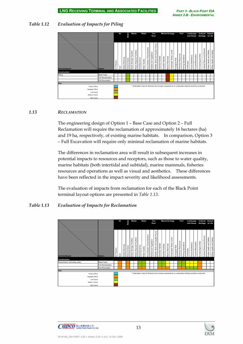
LNG RECEIVING TERMINAL AND ASSOCIATED FACILITIES PART 3 - BLACK POINT EIA ANNEX 2-B - ENVIRONMENTAL
0018180_EIA PART 3 S2.1 ANNEX 2-B V1.DOC 13 DEC 2006
13
Table 1.12 Evaluation of Impacts for Piling
Noi
se
Activity/Hazard Option Air P
ollu
tion
Dus
t
Glo
bal W
arm
ing
Airb
orne
Noi
se
Was
te S
tora
ge F
acilit
ies
Was
te D
ispo
sal F
acilit
ies
Hyd
rody
nam
ics
Wat
er Q
ualit
y
Gro
undw
ater
Cha
ract
eris
tics
Hab
itat a
nd V
eget
atio
n
Wild
life,
Bird
s an
d Aq
uatic
Fau
na
Inte
rtida
l Hab
itats
Subt
idal
Hab
itats
Mar
ine
Mam
mal
s
Und
erw
ater
Noi
se L
evel
s
Ecol
ogic
al R
isk
Fish
erie
s R
esou
rces
Fish
ing
Ope
ratio
ns
Land
scap
e
Visu
al (A
esth
etic
s)
Tour
ism
/Rec
reat
ion
Arch
aeol
ogic
al S
ites
Cul
tura
l Res
ourc
es/G
rave
s
Ons
ite H
ealth
and
Saf
ety
Offs
ite H
ealth
and
Saf
ety
ConstructionPiling Base Case
Full ReclamationFull Excavation
KeyPositive Effect
Negligible Effect
Low Impact
Medium Impact
High Impact
Cultural Heritage
Hazard to Life
Air Waste Water
* Underwater noise for fisheries has not been assessed as no underwater blasting would be conducted
Landscape and Visual
Terr. Ecol.
Fish*Marine Ecology
1.13 RECLAMATION
The engineering design of Option 1 – Base Case and Option 2 – Full Reclamation will require the reclamation of approximately 16 hectares (ha) and 19 ha, respectively, of existing marine habitats. In comparison, Option 3 – Full Excavation will require only minimal reclamation of marine habitats.
The differences in reclamation area will result in subsequent increases in potential impacts to resources and receptors, such as those to water quality, marine habitats (both intertidal and subtidal), marine mammals, fisheries resources and operations as well as visual and aesthetics. These differences have been reflected in the impact severity and likelihood assessments.
The evaluation of impacts from reclamation for each of the Black Point terminal layout options are presented in Table 1.13.
Table 1.13 Evaluation of Impacts for Reclamation
Noi
se
Activity/Hazard Option Air P
ollu
tion
Dus
t
Glo
bal W
arm
ing
Airb
orne
Noi
se
Was
te S
tora
ge F
acilit
ies
Was
te D
ispo
sal F
acilit
ies
Hyd
rody
nam
ics
Wat
er Q
ualit
y
Gro
undw
ater
Cha
ract
eris
tics
Hab
itat a
nd V
eget
atio
n
Wild
life,
Bird
s an
d Aq
uatic
Fau
na
Inte
rtida
l Hab
itats
Subt
idal
Hab
itats
Mar
ine
Mam
mal
s
Und
erw
ater
Noi
se L
evel
s
Ecol
ogic
al R
isk
Fish
erie
s R
esou
rces
Fish
ing
Ope
ratio
ns
Land
scap
e
Visu
al (A
esth
etic
s)
Tour
ism
/Rec
reat
ion
Arch
aeol
ogic
al S
ites
Cul
tura
l Res
ourc
es/G
rave
s
Ons
ite H
ealth
and
Saf
ety
Offs
ite H
ealth
and
Saf
ety
ConstructionReclamation (including Jetty) Base Case
Full ReclamationFull Excavation
KeyPositive Effect
Negligible Effect
Low Impact
Medium Impact
High Impact
* Underwater noise for fisheries has not been assessed as no underwater blasting would be conducted
Landscape and Visual
Cultural Heritage
Air Waste Water Hazard to Life
Terr. Ecol.
Fish*Marine Ecology

LNG RECEIVING TERMINAL AND ASSOCIATED FACILITIES PART 3 - BLACK POINT EIA ANNEX 2-B - ENVIRONMENTAL
0018180_EIA PART 3 S2.1 ANNEX 2-B V1.DOC 13 DEC 2006
14
1.14 SITE FORMATION
Site formation works at each option will involve the consideration of the volume of excavated materials, the potential for afteruse, slope stabilisation and maintenance. It is noted that volumes of excavated material and afteruse are considered under excavation and waste generation and disposal, therefore for the purposes of assessing the environmental consequences of site formation the focus has been to identify any key differences between overall site formation, stabilisation and maintenance.
Each of the three layout options will be prepared, excavated and stabilised in similar formats (see Section 1.7 above). As such, it is expected that the differences between the three layouts will not be significant to differentiate between in terms of environmental impacts. Similar impacts to waste generation and disposal as well as landscape, aesthetics and archaeological resources may then be expected to occur for each layout. Thus, for the purposes of this consideration of alternatives, it has been determined that each layout would have the potential to result in similar environmental impacts to resources/receptors as a result of site formation , regardless of configuration or design.
The evaluation of impacts from site formation for each of the Black Point terminal layout options are presented in Table 1.14.
Table 1.14 Evaluation of Impacts for Site Formation
Noi
se
Activity/Hazard Option Air P
ollu
tion
Dus
t
Glo
bal W
arm
ing
Airb
orne
Noi
se
Was
te S
tora
ge F
acilit
ies
Was
te D
ispo
sal F
acilit
ies
Hyd
rody
nam
ics
Wat
er Q
ualit
y
Gro
undw
ater
Cha
ract
eris
tics
Hab
itat a
nd V
eget
atio
n
Wild
life,
Bird
s an
d Aq
uatic
Fau
na
Inte
rtida
l Hab
itats
Subt
idal
Hab
itats
Mar
ine
Mam
mal
s
Und
erw
ater
Noi
se L
evel
s
Ecol
ogic
al R
isk
Fish
erie
s R
esou
rces
Fish
ing
Ope
ratio
ns
Land
scap
e
Visu
al (A
esth
etic
s)
Tour
ism
/Rec
reat
ion
Arch
aeol
ogic
al S
ites
Cul
tura
l Res
ourc
es/G
rave
s
Ons
ite H
ealth
and
Saf
ety
Offs
ite H
ealth
and
Saf
ety
ConstructionSite Formation Base Case
Full ReclamationFull Excavation
KeyPositive Effect
Negligible Effect
Low Impact
Medium Impact
High Impact
* Underwater noise for fisheries has not been assessed as no underwater blasting would be conducted
Air Waste Water Terr. Ecol.
Fish* Landscape and Visual
Cultural Heritage
Hazard to Life
Marine Ecology
1.15 WASTE GENERATION AND DISPOSAL
All options will require the excavation of rock from the existing hillsides in order to provide sufficient flat land to meet the functional requirements of the LNG terminal. However, as the Option 2 layout design will only require negligible excavation, it is assumed that this material can be re-used onsite. In addition, it is expected that up to 6.5 Mm3 of rockfill will need to be imported, possibly from existing construction and demolition (C&D) waste storage facilities. Hong Kong is currently storing surplus C&D material, thus

LNG RECEIVING TERMINAL AND ASSOCIATED FACILITIES PART 3 - BLACK POINT EIA ANNEX 2-B - ENVIRONMENTAL
0018180_EIA PART 3 S2.1 ANNEX 2-B V1.DOC 13 DEC 2006
15
the necessity to import such material would be considered to be a positive impact for the Option 2 layout. In addition, Option 1 – Base Case would also require the import of 3.77 Mm3 of potentially C&D material.
In contrast to Option 2, the design of Option 3 - Full Excavation will result in a surplus of approximately 14.0 Mm3 of rock following excavation and construction works. This material will be exported to allocated waste disposal facilities and would be considered as a potentially high impact to such facilities.
The evaluation of impacts waste generation and disposal for each of the Black Point terminal layout options are presented in Table 1.15.
Table 1.15 Evaluation of Impacts for Waste Generation and Disposal
Noi
se
Activity/Hazard Option Air P
ollu
tion
Dus
t
Glo
bal W
arm
ing
Airb
orne
Noi
se
Was
te S
tora
ge F
acilit
ies
Was
te D
ispo
sal F
acilit
ies
Hyd
rody
nam
ics
Wat
er Q
ualit
y
Gro
undw
ater
Cha
ract
eris
tics
Hab
itat a
nd V
eget
atio
n
Wild
life,
Bird
s an
d Aq
uatic
Fau
na
Inte
rtida
l Hab
itats
Subt
idal
Hab
itats
Mar
ine
Mam
mal
s
Und
erw
ater
Noi
se L
evel
s
Ecol
ogic
al R
isk
Fish
erie
s R
esou
rces
Fish
ing
Ope
ratio
ns
Land
scap
e
Visu
al (A
esth
etic
s)
Tour
ism
/Rec
reat
ion
Arch
aeol
ogic
al S
ites
Cul
tura
l Res
ourc
es/G
rave
s
Ons
ite H
ealth
and
Saf
ety
Offs
ite H
ealth
and
Saf
ety
ConstructionWaste Generation and Disposal Base Case
Full ReclamationFull Excavation
OperationWaste Generation and Disposal Base Case
Full ReclamationFull Excavation
KeyPositive Effect
Negligible Effect
Low Impact
Medium Impact
High Impact
* Underwater noise for fisheries has not been assessed as no underwater blasting would be conducted
Landscape and Visual
Waste Water Terr. Ecol.
Fish*Air Cultural Heritage
Hazard to Life
Marine Ecology
1.16 ANTIFOULANTS
During the operation of the LNG terminal discharges will include cooled water, as seawater will be used for warming the LNG in the Open Rack Vaporizers. For operational reasons, the discharges will likely contain antifoulants. Although all discharges will be designed to comply with the Water Pollution Control Ordinance Technical Memorandum on Standards for Effluents Discharged into Drainage and Sewerage Systems, Inland and Coastal Waters there is the potential for impacts to occur to marine ecological and fisheries habitats within the surrounding waters.
For the purposes of this consideration of alternatives, it has been determined that each layout would have the potential to result in similar environmental impacts to resources/receptors as a result of antifoulant discharge, regardless of configuration or design.
The evaluation of impacts from antifoulants for each of the Black Point terminal layout options are presented in Table 1.16.

LNG RECEIVING TERMINAL AND ASSOCIATED FACILITIES PART 3 - BLACK POINT EIA ANNEX 2-B - ENVIRONMENTAL
0018180_EIA PART 3 S2.1 ANNEX 2-B V1.DOC 13 DEC 2006
16
Table 1.16 Evaluation of Impacts for Antifoulants
Noi
se
Activity/Hazard Option Air P
ollu
tion
Dus
t
Glo
bal W
arm
ing
Airb
orne
Noi
se
Was
te S
tora
ge F
acilit
ies
Was
te D
ispo
sal F
acilit
ies
Hyd
rody
nam
ics
Wat
er Q
ualit
y
Gro
undw
ater
Cha
ract
eris
tics
Hab
itat a
nd V
eget
atio
n
Wild
life,
Bird
s an
d Aq
uatic
Fau
na
Inte
rtida
l Hab
itats
Subt
idal
Hab
itats
Mar
ine
Mam
mal
s
Und
erw
ater
Noi
se L
evel
s
Ecol
ogic
al R
isk
Fish
erie
s R
esou
rces
Fish
ing
Ope
ratio
ns
Land
scap
e
Visu
al (A
esth
etic
s)
Tour
ism
/Rec
reat
ion
Arch
aeol
ogic
al S
ites
Cul
tura
l Res
ourc
es/G
rave
s
Ons
ite H
ealth
and
Saf
ety
Offs
ite H
ealth
and
Saf
ety
OperationAntifoulants Base Case
Full ReclamationFull Excavation
KeyPositive Effect
Negligible Effect
Low Impact
Medium Impact
High Impact
* Underwater noise for fisheries has not been assessed as no underwater blasting would be conducted
Air Terr. Ecol.
Fish* Landscape and Visual
Cultural Heritage
Hazard to Life
Marine EcologyWaste Water
1.17 COOLED WATER DISCHARGE
As mentioned above, the operation of the terminal is expected to involve the intake of seawater into open rack vaporisers and the discharge of cooled seawater. The volume of seawater intake and the cooled seawater in the effluent has the potential to impact marine ecological and fisheries habitats in the surrounding waters through a localised reduction in water temperature.
As with antifoulants, for the purposes of this consideration of alternatives, it has been determined that each layout would have the potential to result in similar environmental impacts to resources/receptors as a result cooled water discharge, regardless of configuration or design.
The evaluation of impacts from cooled water discharge for each of the Black Point terminal layout options are presented in Table 1.17.
Table 1.17 Evaluation of Impacts for Cooled Water Discharge
Noi
se
Activity/Hazard Option Air P
ollu
tion
Dus
t
Glo
bal W
arm
ing
Airb
orne
Noi
se
Was
te S
tora
ge F
acilit
ies
Was
te D
ispo
sal F
acilit
ies
Hyd
rody
nam
ics
Wat
er Q
ualit
y
Gro
undw
ater
Cha
ract
eris
tics
Hab
itat a
nd V
eget
atio
n
Wild
life,
Bird
s an
d Aq
uatic
Fau
na
Inte
rtida
l Hab
itats
Subt
idal
Hab
itats
Mar
ine
Mam
mal
s
Und
erw
ater
Noi
se L
evel
s
Ecol
ogic
al R
isk
Fish
erie
s R
esou
rces
Fish
ing
Ope
ratio
ns
Land
scap
e
Visu
al (A
esth
etic
s)
Tour
ism
/Rec
reat
ion
Arch
aeol
ogic
al S
ites
Cul
tura
l Res
ourc
es/G
rave
s
Ons
ite H
ealth
and
Saf
ety
Offs
ite H
ealth
and
Saf
ety
OperationCooled Water Discharge Base Case
Full ReclamationFull Excavation
KeyPositive Effect
Negligible Effect
Low Impact
Medium Impact
High Impact
Terr. Ecol.
Fish* Landscape and Visual
Air Waste Water Cultural Heritage
Hazard to Life
* Underwater noise for fisheries has not been assessed as no underwater blasting would be conducted
Marine Ecology
1.18 LAYOUT CHARACTERISTICS
The construction of the reclamation, jetty and dredged areas will result in localised alterations in the water flows (both in terms of velocity and

LNG RECEIVING TERMINAL AND ASSOCIATED FACILITIES PART 3 - BLACK POINT EIA ANNEX 2-B - ENVIRONMENTAL
0018180_EIA PART 3 S2.1 ANNEX 2-B V1.DOC 13 DEC 2006
17
direction). Altered water flows have the potential to result in secondary effects on the sedimentary regime in the vicinity of the site; increased or changed water flow patterns have the potential to result in localised scour (ie. resuspension) of seabed sediments. Conversely the creation of areas of calmer or lower velocity water flows have the potential to result in increased sedimentation effects.
The reclamation requirements for layout Options 1 and 2 may be expected to potentially change the hydrodynamics in the surrounding waters. Impacts as a result of these changes may occur to water quality, marine ecological and fisheries sensitive receivers. In addition, the extended footprint of Option 2 – Full Reclamation would likely increase the exposure to visual sensitive receivers south of the site. Such operational impacts are considered to be a disadvantage of this layout in comparison to the others under investigation.
The evaluation of impacts from the layout characteristics for each of the Black Point terminal layout options are presented in Table 1.18.
Table 1.18 Evaluation of Impacts for Layout Characteristics N
oise
Activity/Hazard Option Air P
ollu
tion
Dus
t
Glo
bal W
arm
ing
Airb
orne
Noi
se
Was
te S
tora
ge F
acilit
ies
Was
te D
ispo
sal F
acilit
ies
Hyd
rody
nam
ics
Wat
er Q
ualit
y
Gro
undw
ater
Cha
ract
eris
tics
Hab
itat a
nd V
eget
atio
n
Wild
life,
Bird
s an
d Aq
uatic
Fau
na
Inte
rtida
l Hab
itats
Subt
idal
Hab
itats
Mar
ine
Mam
mal
s
Und
erw
ater
Noi
se L
evel
s
Ecol
ogic
al R
isk
Fish
erie
s R
esou
rces
Fish
ing
Ope
ratio
ns
Land
scap
e
Visu
al (A
esth
etic
s)
Tour
ism
/Rec
reat
ion
Arch
aeol
ogic
al S
ites
Cul
tura
l Res
ourc
es/G
rave
s
Ons
ite H
ealth
and
Saf
ety
Offs
ite H
ealth
and
Saf
ety
OperationLayout Characteristics Base Case
Full ReclamationFull Excavation
KeyPositive Effect
Negligible Effect
Low Impact
Medium Impact
High Impact
* Underwater noise for fisheries has not been assessed as no underwater blasting would be conducted
Hazard to Life
Air Waste Water Marine EcologyTerr. Ecol.
Fish* Landscape and Visual
Cultural Heritage


![Anti-biofilm activity of ultrashort cinnamic acid peptide derivatives … · concentration (MIC) values for amino terminal peptides in comparison to C-terminal carboxylic acids [5].](https://static.fdocuments.in/doc/165x107/5e7b8d816eee715f350c344d/anti-biofilm-activity-of-ultrashort-cinnamic-acid-peptide-derivatives-concentration.jpg)