
CONTAINERSHIP UNDER COMBINED LOADING OF … · ssc-243 (sl-7-3) structural analysis of sl-7...
60
.- SSC-243 (SL-7-3) Q % “J i STRUCTURAL ANALYSIS OF SS-7 CONTAINERSHIP UNDER COMBINED LOADING OF VERTICAL, LATERAL AND TORSIONAL MOMENTS USING FINITE ELEMENT TECHNIQUES This document has been approved for public release and sale; its distribution is unlimited. SHIP STRUCTURE COMMITTEE 1974 ,,.— ._ .
Transcript of CONTAINERSHIP UNDER COMBINED LOADING OF … · ssc-243 (sl-7-3) structural analysis of sl-7...
.-
SSC-243
(SL-7-3)
Q%“J
i STRUCTURAL ANALYSIS OF SS-7CONTAINERSHIP UNDER COMBINED LOADING
OF VERTICAL, LATERAL AND TORSIONALMOMENTS USING FINITE ELEMENT TECHNIQUES
This document has been approvedfor public release and sale; its
distribution is unlimited.
SHIP STRUCTURE COMMITTEE
1974
,,.— ._ .
SHIP STRUCTURE COMMl~EEAN INTERAGENCYADVISORY
COMMITTEEDEDICATEDTO IMPROVINGTHE STRUCTURE OF SHIPS
MEMBER AGENCIES: ADDRESSCORRESPONDENCE TO:UNITED STATES COAST GUARD SECRETARY
NAVAI SHIP SYSTEM5COMMAN0
MILITARY SEALIFT COMMAND
SHIP STR(JCTURE COMMITTEE
U.S. COAST GUARD HEA130UAR1EHS
MARITIME ADMINISTRATION WASHINGTON,’D.C. 20590
AMERICAN BLIREAU OF SHIPPING
SSC-243
8 AUG ?974This report is one of a group of Ship Structure Committee Reports
which describes the SL-7 Instrumentation Program. This program, a jointlyfunded undertaking of Sea-Land Service, Inc., the American Bureau of Shipping“andthe Ship Structure Committee, represents an excellent example of coop-eration between private industry, regulatory authority and government. Thegoal of the program is to advance understanding of the performance of ships’hull structures and the effectiveness of the analytical and experimentalmethods used in their design. While the experiments and analyses of theprogram are keyed to the SL-7 Containersh<p and a considerable body of datawill be developed relating specifically to that ship, the conclusions of the
program will be completely general, and thus applicable to any surface shipstructure.
The program includes measurement of hull stresses, accelerationsand environmental and operating data on the SS Sea-Land McLean, developmentand installation of a microwave radar wavemeter for measuring the seawayencountered by the vessel, a wave tank model study and a theoretical hydro-dynamic analysis which relate to the wave induced loads, a structural modelstudy and a finite element structural analysis which relate to the structuralresponse, and installation,of long term stress recorders on each of the eightvessels of the class. In addition, work is underway to develop the initialcorrelations of the results of the several program elements.
Resul”tsof each of the program”elements will be published as ShipStructure Committee Reports and each of the reports relating to this programwill be identified by an SL- designation along with the usual SSC- number.A list of all of the SL- reports published to date is included on the backcover of this report.
This report contains the finite element structural analyses ofthe vessel.
W. M. BenkertRear Admiral, U. S. Coast GuardChairman, Ship Structure Committee
,-
SSC-243
(SL-7-3)
STRUCTURAL ANALYSIS OF SL-7 CONTAINERSHIP
UNDER COMBINED LOADING OF VERTICAL, LATERAL AND
TORSIONAL MOMENTS USING FINITE ELEMENT TECHNIQUES
by
A. M. Elbatouti, D. Liu, and Ii. Y. Jan
American Bureau of Shipping
This document has been approved for pub’Ziemkasa andsale; its distmhtion is unlimited.
U. S. Coast Guard HeadquartersWashington, i).C,
1974
ABSTRACT
The entire SL-7 container vesrel hull structure is analyzed bythe DAISY finite element computer program. The ship, loaded with con-tainers, placed in oblique quasi-static regular waves, is subject .to com-bined vertical, lateral and torsional loads. Stress distributions par-ticularly in the deck region are presented and investigated from the anal-ysis using the reduced element substructure feature in the program. Finemesh analyses are also presented at different locations of the ship. Thecomputed stresses are discussed in connection with the placement of straingages instrumentation on the “SEA-LAND McLEAN”.
-ii-
CONTENTS
PAGE
1
CHAPTER
I INTRODUCTION
3II LOADINGS AND STRUCTURAL MODE LLING
Loading on the Vessel 3
7Structural Modelling
Boundary Supports
111 RJZSULTS AND DISCUSSION
Displacements
Stresses 16
General Ship Response to Combined
Longitudinal, Lateral and Torsional
Moments
Substructure General Response
Section Frame 222
Section Frames 156–158 23
23Section Frames 188–192
23Deck Wing ROX Forward to Engine
Room Frames 142-150
Wing Box–Transverse Box Connection
Frames 176–182
37Stress Distribution in Connection
with Strain Gauge Instrumentation
CONCLUSIONS AND COMMENTS
RJ?.FERJ?JJCESAND ACKNOWLEDG~NT
-iii-
LIST OF FIGURES
—--. -—-
Wave Geometry
First Loading Case (curves)
Second Loading Case (curves)Loads, Use of Symmetry and Anti–Symmetry
SL-7 General ArrangementSL–7 Typical Section
Coarse Mesh Model bef~re SubstructuringSubstructure LayoutSubstructure ModelsSubstructure Grid Form (9B as an example)
Fine Mesh Models OutlineFine Grid Form (model 1 as an example)
Overall Displacement, First Loading CaseDeformation of Transverse Box Fr. 160.
Deformation of Transverse Box Fr. 17S.
Predicted Distribution of Stress Component
Wing BOX Stress Response
Total Longitudinal Stresses Fr. 222.
Vertical Bending Longitudinal Stresses E’r. 222.Anti–symmetric Longitudinal Stresses Fr. 222.
Total Shear Stresses Fr. 222.Shear Stresses Due to Vertical Bending Fr. 222.Shear Stresses Due to Anti-symm. Loading Fr. 22.2.Lateral Bending Stresses and Shear Stresses Fr.157.
Torsional Stresses Fr. 157 %/2.Wave Induced Vertical Bending and Shear StressesFr . 190.
“Longitudinal and Transverse Stresses, Port S&d@Sub . 142-150.
Longitudinal and Transverse Stresses Starboard Side
Sub . 142-150.Fine Mesh:M. Ilk. Longitudinal Stresses Fr.142-146Wave Induced Vertical Bending Stiresses Fr.142-146
Lateral Bending and Torsional St_resses F.r.142–146Stress Resolution of Trans. Box Fr. 178
Longitudinal and Transverse Stresses, Port SideSub. 168-178.Longitudinal and Transverse Stresses, Starboard SideSub. 168-178.M. 13k. Longitudinal St-resses Model 1, Fine Mesh
S~bstructure vs Fine Mesh Results Model 1
Trans. Stresses of Trans. Box Fr. 178
-iv-
E’AGE
4
556788991212‘12I.(j151617
182020212%
2222
2425
26
27
28
2930
30
3132
33
3434
35
LIST OF FIGURES (L’ont’d)
1?llGURE
38
39
40
41
42
43
4445
46
47
48
?Wl~~-S~m. stresses, -Trans. Box F~. ~78
First L.C.
~Ilti-Symm. Stresses, Trans. Box ~~. 178Second L.c.Hatch distortion vs. Stresses Fr. 178
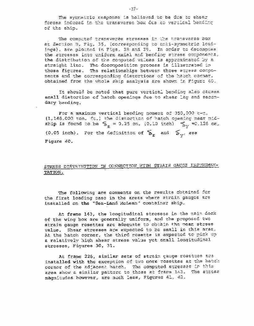
Longitudinal and Trans. Stresses, P.S.,
Sub . 226-235
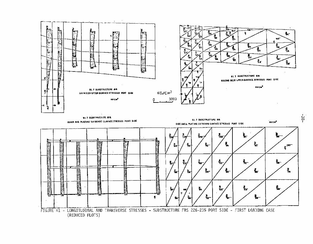
Longitudinal and Trans. Stresses, Starboard SideSub . 226-235Coarse Mesh Deck Stresses, STBD, Fr.234 Forward
Coarse Mesh Deck Stresses, P.S., Fr.234–FoNardLongitudinal and Trans. Stresses, Port Side
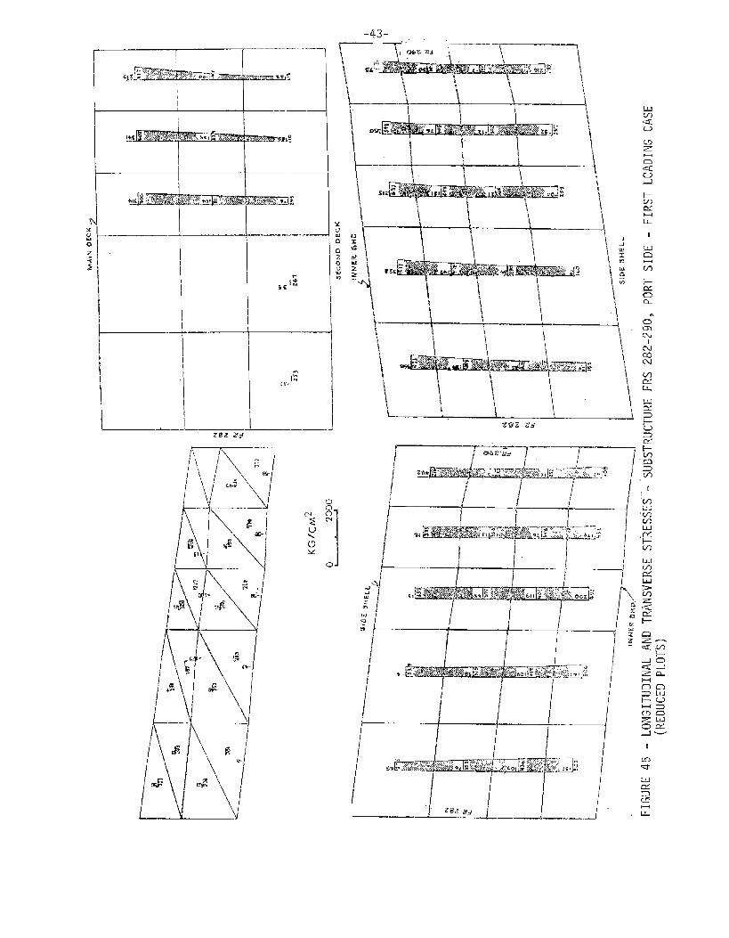
sub . 282-290
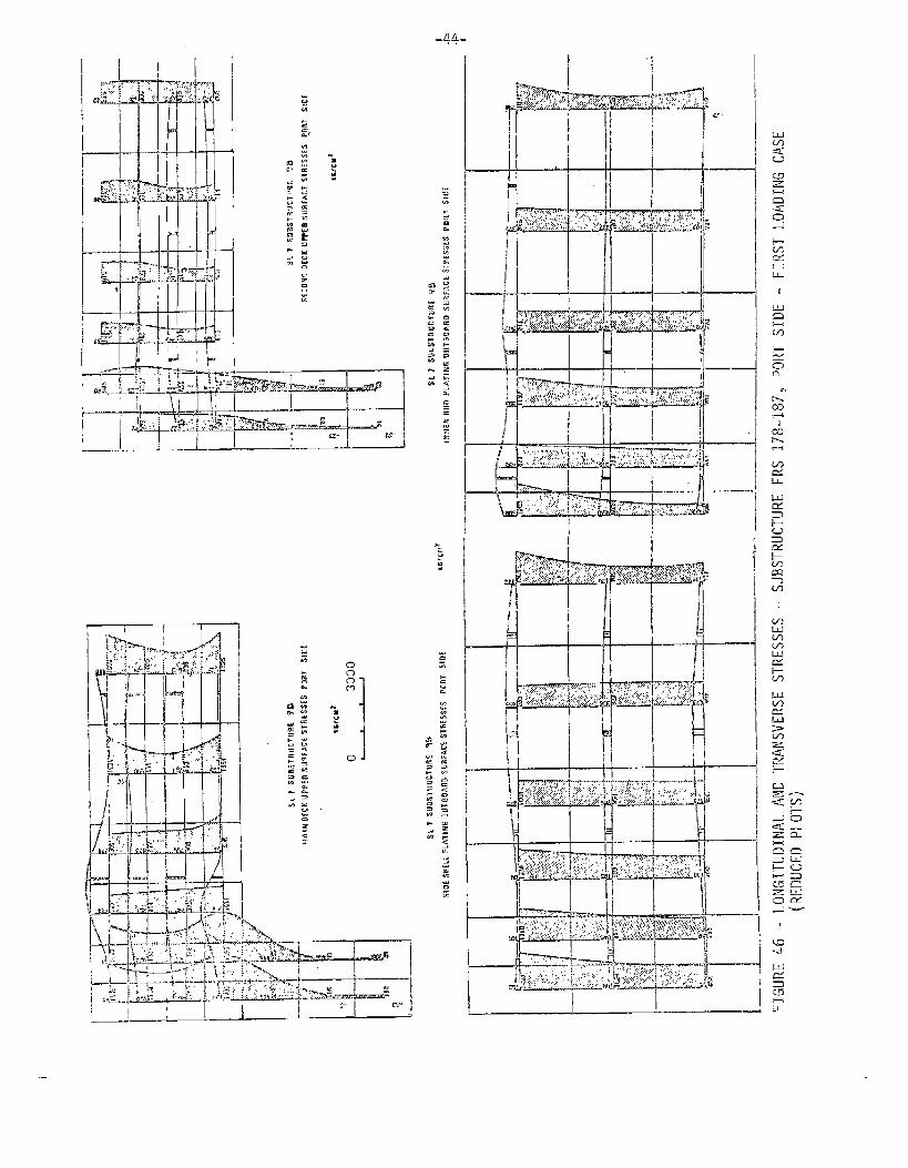
Longitudinal and Trans. Stresses, Port SideSub. 178-187
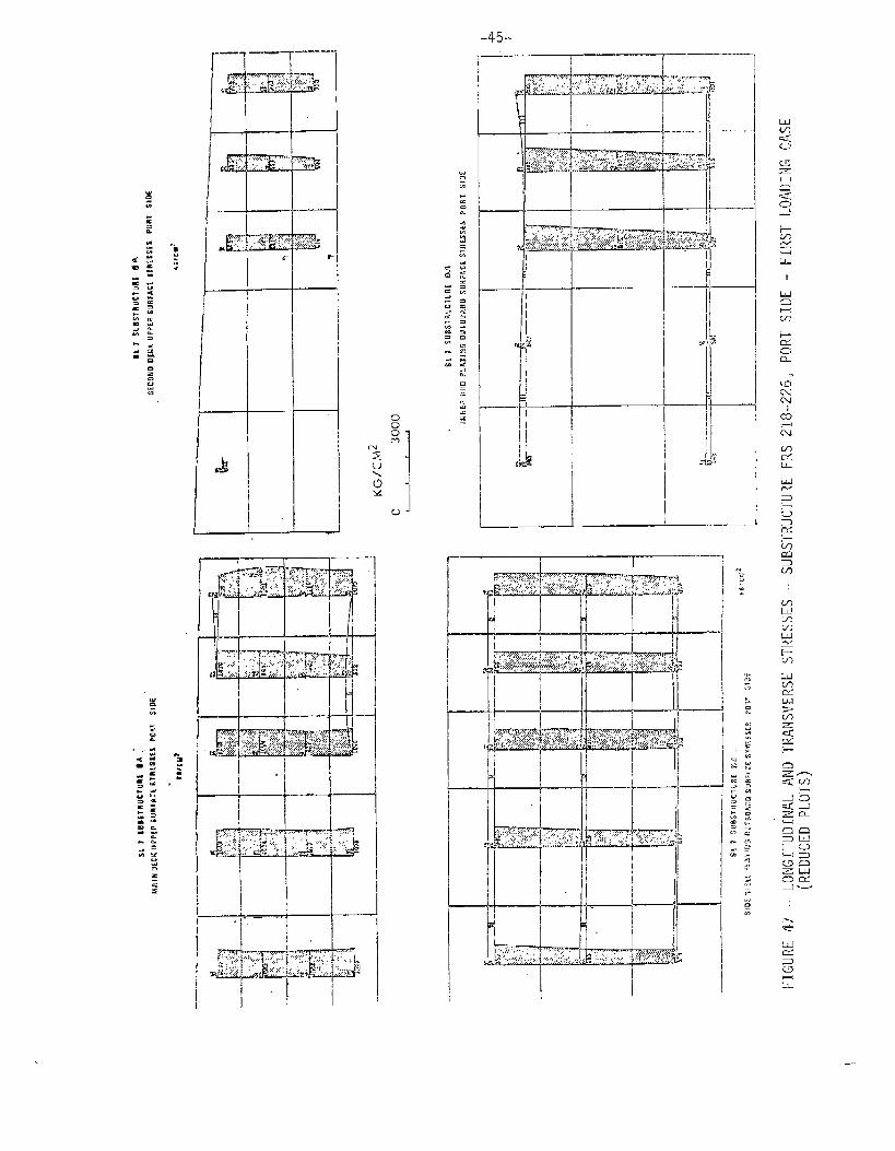
Longitudinal and Trans. Stresses, Port Side
Sub . 218-226
Longitudinal and Trans. StressesJ Starboard SideSub. 218-226
PAGE
35
36
3638
39
401
4143’
44
45
46
-v-
SHIP STRUCTURE COMMITTEE
The SHIP STRUCTURE COMMITTEE Is constituted to prosecute a researchprogram to Improve the hull structures of ships by an extension of knowledgepertaining to design, materials and methods of fabrication.
RADhlW. N. Benkert, LJSCG, ChairmanChief, Office of Merchant Marine Safety
U.S. Coast Guard Headquarters
CAPT J. E. Rasmussen, USN PIT.M. PitkinHead, Ship Systems Engineering Asst. Administrator for
and Design Department Commercial DevelopmentNaval Ship Engineering Center Maritime Aclmin~stratlonNaval Ship Systems Command
Mr. K, Morland CAPT L. L. Jackson, USNVice President Maintenance and Repair OfficerAmerican Bureau of Shipping Military Sea7ift Command
SHIP STRUCTURE SUBCOMMITTEE
The SHIP STRUCTURE SUBCOMMITTEE acts for the Ship Strudture Committeeon technical matters by providing technicalof goals and objectives of the program, andresults in terms of ship structural design,
NAVAL SHIP SYSTEMS COMMAND
Mr. P. M. Palermo - MemberMr. J. B. O’Brien - Contract AdministratorMr. G. Sorkin - MemberMr. C. H. Pohler - Member
U.S. COAST GUARD
CDR C. S. Loosmore - SecretaryCAPT D. J. Linde - MemberCDR E. L. Jones - MemberCDR W. PI.Devlin - Member
MARITIME ADMINISTRATION
Mr. J. J. Nachtsheim - ChairmanMr. F. Dashnaw - MemberMr. F. Seibold - MemberMr. R. K. Kiss - Member
MILITARY SEALIFT COMMAND
Mr. R. R. Askren - MemberMr. T. W. Chapman - MemberCDR A. McPherson, USN - MemberMr. A: B. Stavovy - Member
ANIERICAN BU~~i~ OF ~HIPPING
Mr. S. G. Stlansen - PlemlserMr. 1. L. Stern - Member -vi-
coordlnation for the determinationby evaluating and interpreting theconstruction and operat~on.
NATIONAL ACADEMY OF SCIENCES.Shlp Research Committee
W. R. M. Rumke - LiaisonProf. J. E. Goldberg - Liaison
SOCIETY OF NAVAL ARCHITECTS & MARINEENGINEERS
Mr. T. M. 13ue!rmann- Llalson
5R~T~SH NAVY STA~~
CDR P. C. Bryan, RCNC - Liaison
WELDING RESEARCH COUNCIL
Mr. 1(.1-1.Kooprnan- Liaison
INTERNATIONAL SHIP STRUCTURES CONGRESS
Prof. J. H, Evans - Liaison
U.S. COAST GUARD ACADEMY
CWWTER I
Introduction
The finite element analysis of the entire hull structure of
the SL-7 container ship is an effort towards better understandingof the response of container ships in an oblique seaway.
With batch openings approaching 85% of the .sl~ip”sbeam, the
torsional rigidity of the container ship9s hull girder is con–
siderably different from that of the traditiona~ cargo shiD whose
torsional rigidity ‘was approximated by the assumption of a-closed
box hull girder cross section. Further, the abnupt changes indeck stiffness ak the engine room housing and at the closed ends
of the vessel i-nay accentuate longitudinal stresses due to thewarping restraint present at these locatiion.s. Numerous ques~ionsand spec~~a’~~ons were raised concerning the skress level aT@/Or
deformations at various locations of the deck structure. AccoTd–ingly, the reduced element substructure techmi~ue is used in thefinite element modelling of these areas of concern. (~)o (s)’~.
The reduced element substructure approach can briefly be
described as a local analysis of a refined model within tlhe over-all analysis. An automatic process for reducing &he in-keractivefreedoms :between the substructure and the rest_ of the structure
using interpolation functions is employed. The more refinedlocal model is integrated within the computation of the overall
ship analysis and local resulb can be automatically generated.
The procedure is comparable to finite element substructuring,with the exceptior. that the desirable feakure of interpolationof boundary displacements is automatically provided for. This
feature is most useful in the transition region between a fineand. coarse grid, wherein interpolation ensures displacementcompatibility between adjacent elements. (3)0 Chapter 11 de–scribes the ship modelling in further detail.
Preprocessor Proqrams
1.
2.
3.
4.
SHIP MOMENT -——
-.L-
with the vessel’s lines, steel, fuel and
cargo weight distributions. and wave profile specified,
the program performs a static balance of the vessel todetermine sinkaqe and trim. Vertical shear and bending
moments are calculated, and for a vessel in oblique waves,
inertia loads are introduced so that quasi–static values
of lateral and torsional moments are obtained.
EXAM – generates the finite element structural model ofthe hull structure. Using few inputs with the SEUPMOM
outputs of draft, trim and wave profile, EXAM also auto–
matically calculates the hydrostatic pressures at node
points in the model,
EXPLOT - provides a C.ALCOMP line plot of the model gener-
ated by EXAM. !rhe plots are two-dimensional and indicate
nodal points and freedom patterns, as well as the elements.
Plots of any or all of the structural portions of thevessel cau be made.
LOADER – takes the EXAM output and rearranges it in a—manner suitable for the DAISY program. It calculates the
statically consistent nodal point loads from the nodal
pressures provided by EXAM. I’t also calculates the weight
of the individual structural elements and translates -them
into nodal point loads.
Stress plotting is carried out by a postprocessor program
called “STRPLOT’U. It generates CALCOMP plots of the DAISYP calculated stresses, either as principal stresses or coordinate
stresses.
-3-
CHXPTER 11
LOADINGS AND STRUCTURAL MODELLING
Loadincr on the Vessel
Forces acting an
“inertia forces, fuel,and cargo weights are
tally calculated from
the vessel consist of its own steel weight.cargo ‘weight, and sea way loads. The steel
well defined. Steel weights are automati–
the geometric properties of the structuralelements used in the model. The fuel loads are distributed onthe tank bottom nodes. The container weights are represented asconcentrated point loads acting on the double bottom and crossdeck members, at the container corner locations. Inertia loadsare estimated from the mass distribution of the vessel. and are
applied so as to place the vessel in dynamic equilibrium. The
sea loads are computed from the program SHIPMOM for the ship
poised statically on a wave. Although this static calculation
is admittedly highly idealized, a &omparison had been made of theIongitiudinal strength calculations for the vessel fully loaded bystatic and dynamic methods. For the latter, the strip theorycalculations as described by Grim (2) are used for comparison.
Using a half wave height of 1.01 h0”4 where A is the wavelengthin feet, and calculating the longitudinal bending moments forvarious wavelengths and headings, both methods of calculation
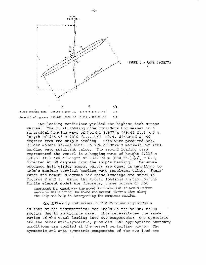
indicated the same critical loading condition. The condition that0 to a wave of one-half the ship lengththe vessel is heading 60
(wave crest amidships] produced the critical loading, Figure 1.In general, the static values are usually on the high side. How’-ever, an equivalent static simulation which produces the same
magnitudes of sea loadings, considering some of the dynamic ef-’fects , seems a proper approximation for the time ,being.
Although the number of loading conditions that can be han–died by the DAISY program is virtually unlimited, only a seleckednumber of conditions were used in the DAISY analysis in view of
the time and manpower required to analyze the computed results of
each. The number of load conditions for the SL–7 container shipwas six. For all conditions, the vessel was considered to carrya full load of fuel and containers, and only the vessel’s load–ing and wave configuration were varied. Among the conditionsanalyzed by the DAISY program were the head wave and still–water
condition, as well as several cases with the vessel headed 60°
to various waves.
-4-
WAVE
DIRECTION
II
[
—— —— ———---
]/
I
d.w“/“’’”// \
/’.’1\\\
-+-,“ \i-A
\
FIGURE 1 - W,VE GEOMETRY.
First loading case 246.95 m (810 ft] a.972 m (.39.43 ft) 0.9
EcconcI loading case 192.073m (630 ft) s.112 m (26.61 ft) 0.7
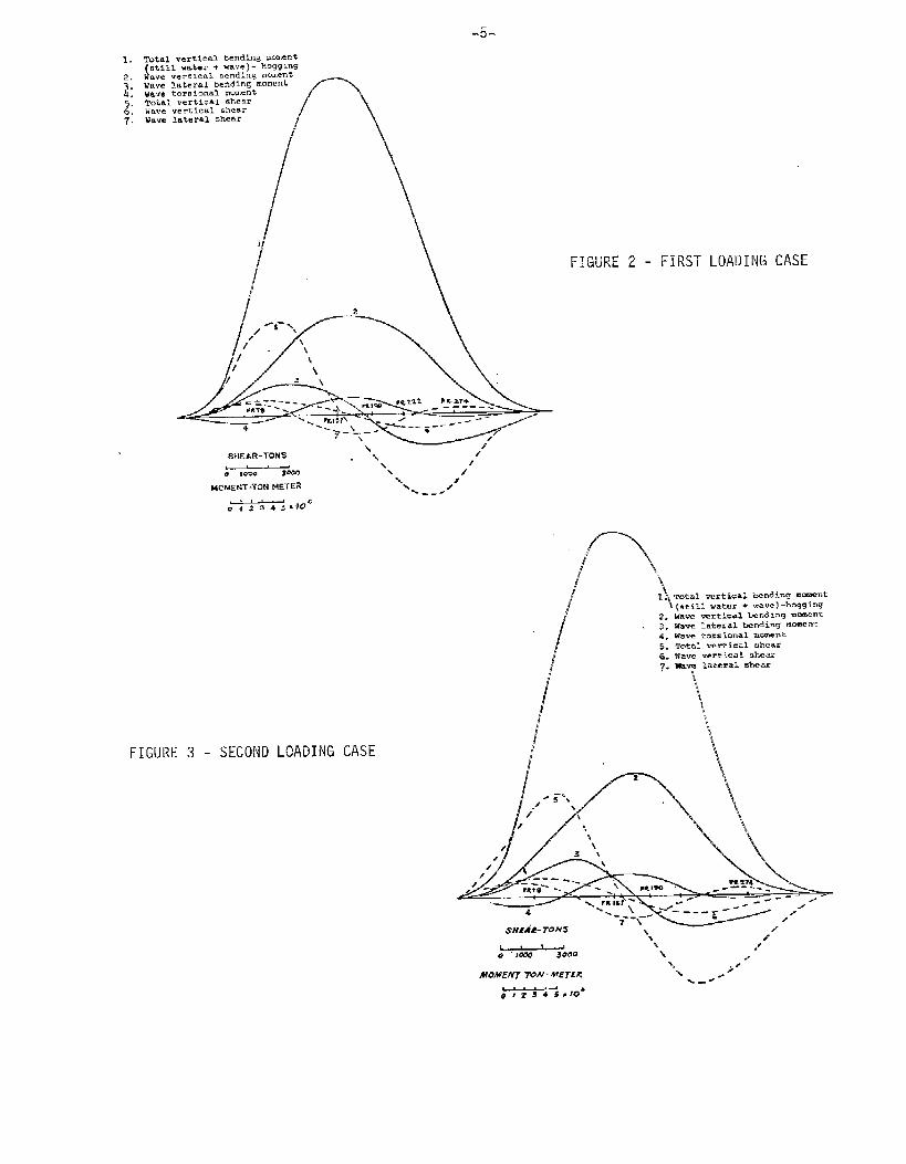
TWO loading conditions yielded &he highest deck stressvalues. The first loading case considers the vessel in asinusoidal hogging wave of height 8.972 m (2’3.43 ft.) and alength of 246.95 m (810 ft..), )i\h =0.9, directed at 60degrees from the ship’s heading. ~~is wave prcduced hull
girder moment values equal to 75% of Grim’s maximum vertical
bending wave resultant value. Tb.e second loading case
represented the vessel iv. a hogging wave of Ineight 8.112 m{2~.61 ft.) and a ~eng~~ of 192.(373 m (630 fk.),)j~~ = 0.7,
directed at 60 degrees from the ship’s heading. Tne wal,7e–
produced hull girder moment values are equal in magnitude to
Grim’s maximum vertical bendirq wave resultamk val~le. shear
force and moment diagrams for these loadings are shown in
Figures 2 and 30 Since khe act-dal loadings applied on thefinite element model are discre’ce~ these curves do not
is
represmt the &xact way the model is loaded but it would ra~~erserve in visualizing tlheforce and moment distribution alongthe ship and help in interpreting the omputer results.
One diffimulw that arises ti this mntainer ship analysis
that of the unsymmetrical sea loads on the ;essel cross
section due to an oblique wave. This necessitates the sepa–
ration of the total loading inko two components : one symmetric
and the other anti–symmetric, provided that appro~ziatie boundary
conditions are applied at. the vessel centerline plane. The
symmetric and anti–symmetric components of the sea load are
—-5-
FIGURE 2 - FIRST LOADING CASE
FIGURE 3 - SECOND LOADING CASE
“\\
\ >-Mo.w.WTTON- METER ‘-% .
%-~
4#z3450Joa
-6-
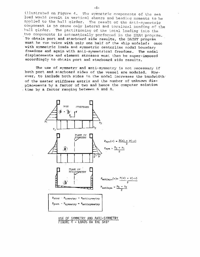
illustrated cm Figure 4.. The syiwnetric compon~nts o? the seaload would result. in vertical shears and bendir.g moments to beaplL>l.iedto the hull girder. TIIe result of the anti–symmetriccomponent is @ cause only la’wral and torsional bending of the
.hul.l girder. The pa~titionirlq of the total loading into thetwo compon~nts is automatically performed in the EX2W proqram.
To obtain port and starb~ard side results, the DAISY program
must be run twice with only one half of the ship modeled: oncewith symmetric loads and symmetric centerline nodal boundaryfreedoms and again with anti–symmetrical freedoms. The nodaldisplacements and element stresses must then be super–imposed
accordingly to obtain port and starboard side results.
The use of symmetry and anti–symmetry is not necessary if-
both port and starboard sides of Lhe vessel are modeled. How-ever, to include both sides in the model increases the bandwidth’
of the master stiffness matrix and the number of unknown dis–
placements by a factor of two and hence the computer solution.time by a factor ranging between 6 and 8.
J’.:“p
MATE OF
Iymmy
i,,’~ i \--\—\
1 J,
Ip]+P~
F7
P=m(x) = p(x) +P-x
2
Pgym = % + PI
2
,U?IAtJE OF “
MJTISSETRY
1.
(b’ i‘antis~(x)= ‘[x) - *(-XJ
2
P PI - P2antisym ‘ _
2
‘sthd = ‘s.ymwhry - Pantisymnetry
pport “ ?Sm,etry + ‘antisymnetry
USE OF SYMMETRY AND ANTI-SYMMETRYFIGURE 4 - LOADS ON THE SHIP
-7-
S+RWTURil’ MODELLING
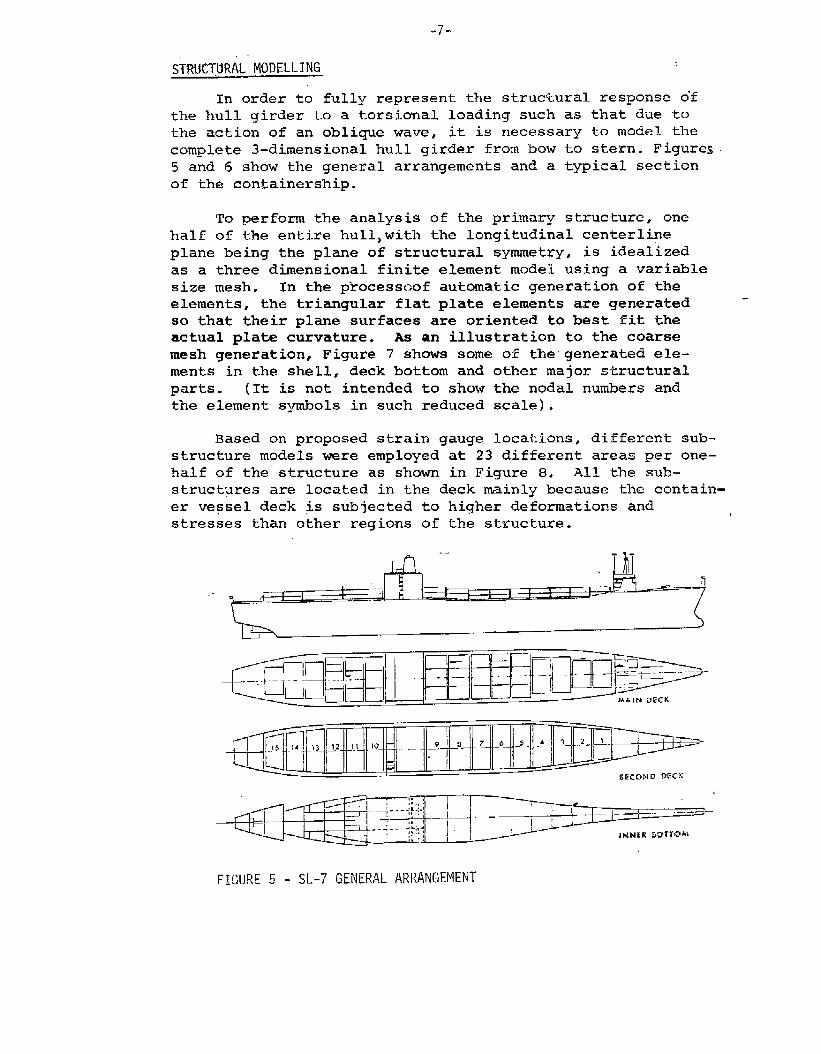
In order to fully represent the structural response o-f
the hull girder to a torsional loading such as that due tothe action of an oblique wave, it is necessary to model the
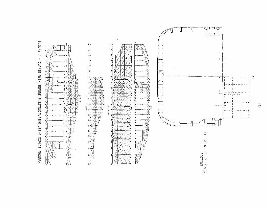
complete 3-dimensional hull girder from bow to stern. Figures
5 and 6 show the general arrangements and a typical sectionof the con$ainership.
To perform the analysis of the primary structure, one
half of the entire hull,with the longitudinal centerline
plane being the plane of structural symmetry, is idealized
as a three dimensional finite element model using a variable
size mesh. In the processoof automatic generation of theelements, the triangular flat plate elements are generatedso that their plane surfaces are oriented to best fit &heactual plate curvature. As an illustration to the coarsemesh generation, Figure 7 shows some of the”generated ele-
ments in the shell, deck bottom and other major structural
parts. (It is not intended to show the nodal numbers andthe element symbols in such reduced scale).
Based on proposed strain gauge locations, different sub-
structure models were employed at 23 different areas per one–half of the structure as shown in Figure B. All the sub-structures are located in the deck mainly because the contain-
er vessel deck @ subjected to higher deformations andstresses than other regions of the structure.
.-
1
t
J I —-
?
FIGURE 5 - SL-7 GENERAL ARRANGEMENT
I
(!0I
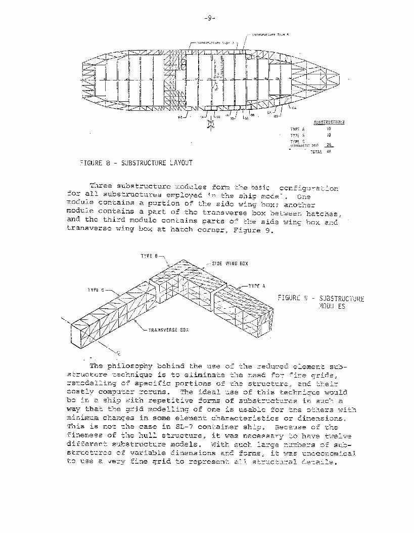
-9-
—Suhotruct. v ‘meAI
.
FIGURE 9 - stii7sTRucTlJREMODULES
_lo_
The chosen mesh is believed to give a fair indication as to
the stress level in the substructure. Also it would be enough
to represent the true stiffness of its major structural members.The reduced element substructure which indicates high stress
levels has been remodeled with very fine grids in order toobtain detailed stress distributions. Here all structural mem–
hers are considered in the fine grid models. The table on page 11provides more information about the problem size and the type ofelements employed in the analyses.
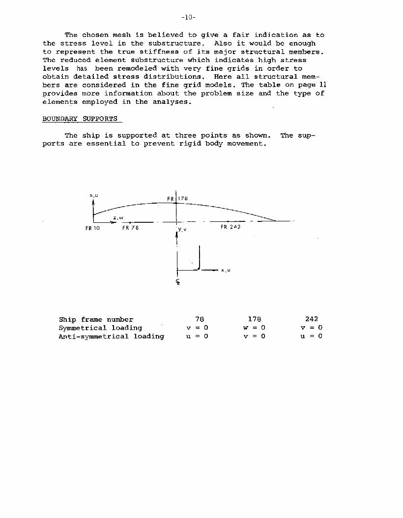
BOUNDARY SUPPORTS
The ship is supported at three points as shown. The sup-ports are essential to prevent rigid body movement.
X,u
#Ff! 178
Z,w—. — -
FR 10 FR 78 “Y.vFR 242
I
u— X,u
Ship frame number 78
Symmetrical loading V=o
Anti-symmetrical loading U=o
178 242
W=o V=o
V=o U=o
-11-
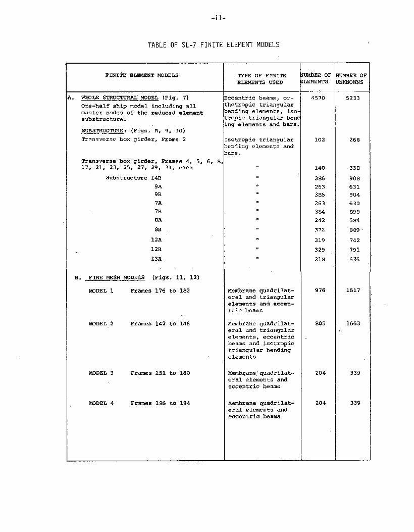
TABLE OF SL-7 FINITE ELEMENT MODELS
FINI’iEELEMENTMODELS
i. WHOLE STRUCTURAL-MODEL (Fig. 7)
One-half ship model including allmaster nodes of the reduced elementsubstructure.
SUBSTRUCTURE : (Figs. 8, 9, 10)
Transverse box girder, Frame 2
Transverse box girder, Frames 4, 5. 6. 817, 21; 23, 25,-27, 24, 31, each
Substructure
,-
13. FINE MESH MODELS
14B
9A
9B
7A
7B
8A
8B
12A
12B
13A
(Figs. 11, U)
MODEL 1 Frames 176 to 182
MODEL 2 Frames 142 to 146
MODEL 3 Frames 151 to 160
WDEL 4 Frames 186 to 194
TYPE OF FINITE
ELEMENTS USED
ccentric beams, or-thotropic triangularending elements, isoropic triangular benng elements and bars
sotropic triangularending e~ements andars.
u
M
,1
I*r,
,,
“
,,
11
n
,,
Membrane quadrilat-eral and triangulareIements and eccen-tric beams
Membrane quadrilat-eral and triangularelements, eccentricbeams and isotropic
triangular bendingelements
Membrane:quadri lat-eral elements andeccentric beams
Membrane quadrilat-eral elements andeccentric beams
tiER OFLEMENTs
4570
102
140
386
263
386
263
384
242
372
319
329
218
976
805
204
204
UMBER OFNKNOWNS
5233
268
338
908
631
904
630
899
584
889
742
791
536
1617
1663..
339
339
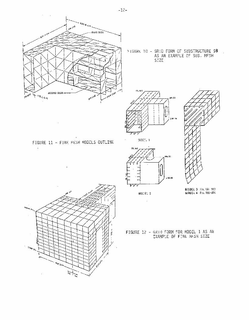
-12-
FIGURE 10 - GRID FORM OF SUBSTRUCTURE 9BAS AN EXAMl]LE OF SUB. MESHSIZE
FIGURE 11 - FINE MESH MODELS OUTLINE
MODEL2
FIGURE 12 - GRID FORM FOR MODEL 1 AS AN
DISPLACEMENTS,—.. —
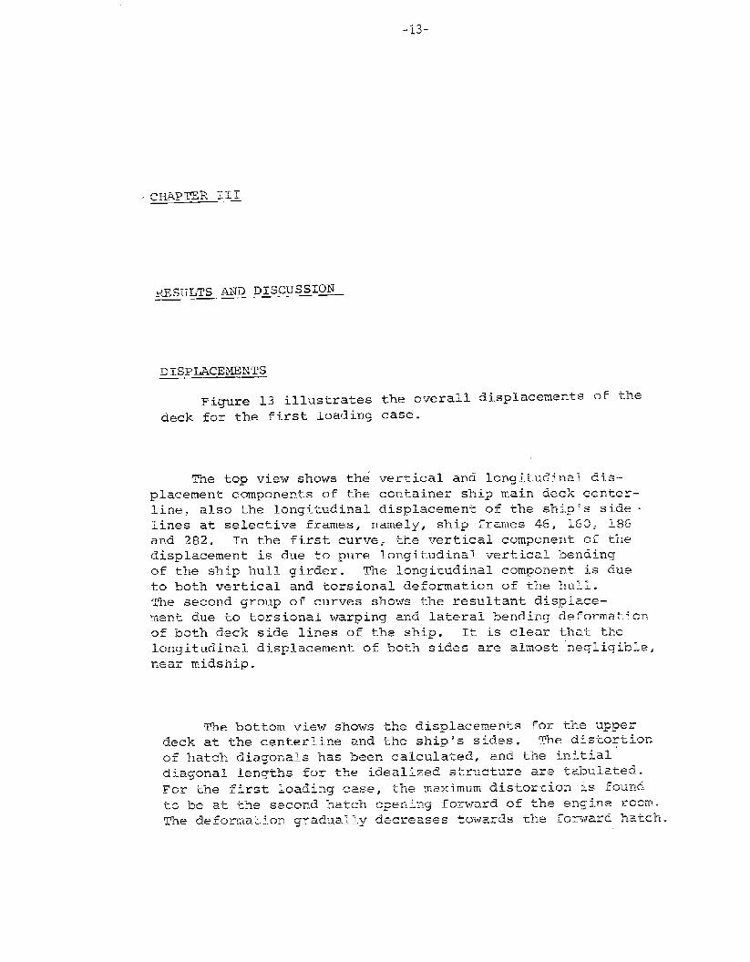
Fiq.lre 13 illustrates the overall displacements 05 the
deck. for the first loading case.
‘I’hetop view shows khi vertical and longitudinal dis–
placement components of the container ship main deck center–
liner also the longitudinal displacement of the ShiRos side ‘
lines at selective frames, namely, ship frames 46r 150, ~%and 282. In the first curver the vertical component of thedisplacement is due to pure longitudinal vertical bending
of the ship hull girder. The longitudinal component is due
to both vertical and torsional deformation of the hull.The second group of curves shows ‘r-heresultant displace–
ment due to torsional warping and lateral “bending deformationof bobh deck side lines of tune ship. lt is clear that thelongitudinal displacement of both sides are almost “negligible,
near midship.
~ne bottom view shows the displacements for the ‘dppe~deck at the centerline and the ship’s sidss. The distortion
of hatch diagonals has been calculated, and the initialdia~onal Ienqths for Yne idealized skr’aetw.re are tiahu~~tie~~.
For the first loading case, the maximum dis-~arkion is found
to be at the second hatch opening forward of the enqine room.
The deformation gradually decreases towads tYJe forward hatch.
HATCH DIAGONAL EXPANSION IN CM“’..<,~
HATCH MO. I 2 3 4 .5 6 7 8 9
d 2048.197 2046,749 2494.283 2494.189 ‘--- – ‘7’“-“-2969.781 296?.800 2965.790 3036.431 303&46? IF
EXPANSION 0.382 0,634 0.896 .125 1.510 2.056 1.989 2.413 1.695 -P
EC< L“.’P1”wu ANO , Al~R_AL OISPLASUI%l S
FIGURE 13 - OVERALL DISPLACEMENTS OF SL-7 DECK AND FRONT HATCHES DIAGONAL EXPANSIONSi,
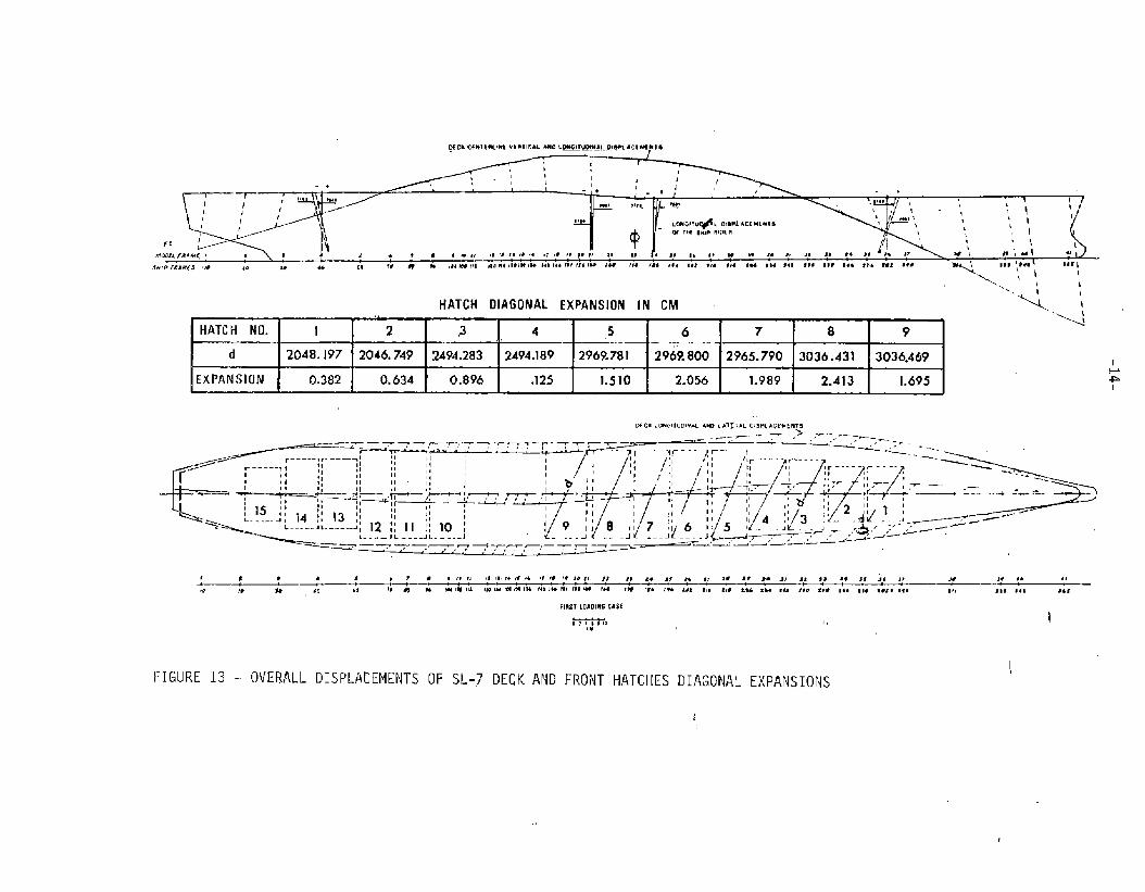
Figurs 14 shows the local deformation ‘f ‘he ‘ransverse
box girders at ship frame 160. It shows the total deformation
of the transverse box substructure at frame 160 and the decom-
posed deformation of the edge AA to symmetric and anti-sym-
metric components. The deflectad shape is plotted relative to
a midpoint on the box top. This allows us to visualize the
substructure end distortions and the symmetric deformationdue to shear lag in the transverse box.
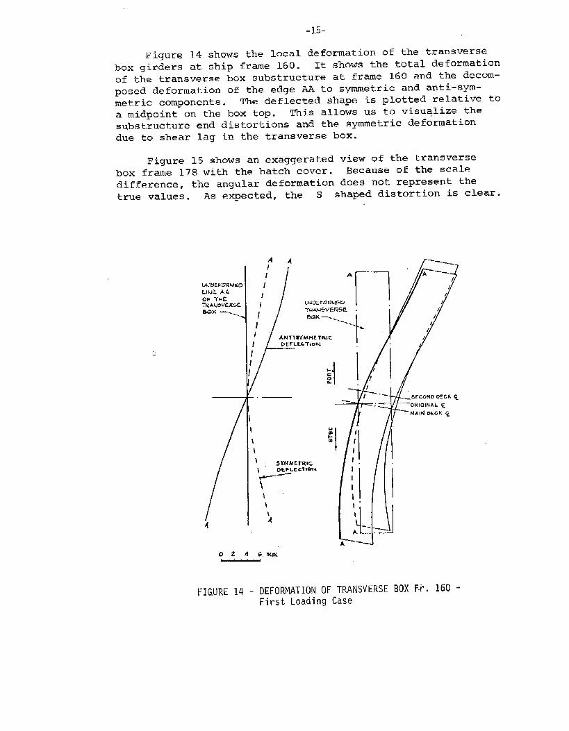
Figure 15 shows an exaggerated view of the transverse
box frame 178 with the hatch cover. Because of the scale
difference, the angular deformation does not represent thetrue values. AS expected, the S shaped distortion is clear.
A?
I
II
/
II
AIUTISYMMETRIC
/’
t
-.— SECOND DECK ~
I 0
\
\
\ SYMME1711C
‘yc’T-
i“ I
\ 1’
\ 1A
-.A‘-. -J
i-----d0 Z A 6.IUVL
FIGURE 14 - DEFORMATION OF TRANSVERSE BOX F-i. 160 -First Loading Case
-~l~_
ItiRELATIOX70TEEUNDEFLECTED$WUCTIJQETHEDEFLECTIONISMAQNIFIE3APP%OXIMA7LL?300TIMES
Fro 178 -
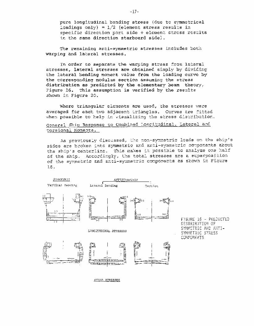
16.
ANTISYMm~Z’C
I rLe.te?al Bending T02-s Lon
-18-
Figure 16 shows predicted stress distributions based upon
general structural response of a simple prismatic hull girder.
Although we do not expect to have exact similar response from
the finite element structural madel, the stress distributionshould generally have the same trend as those predicted above.Exceptions could be made for the stress distributions around
the side wing boxes since the predicted stress distributions donot include many structural members as used in the substructureanalysis.
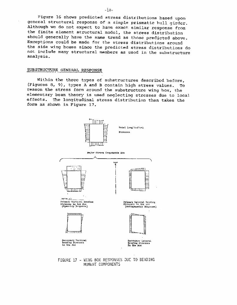
SUBSTRUC7?u~ GENERAL RESPONSE
Within the three types of substructures described before,
(Figures 8, 9), types.A and B contain high stress values. To
reason the stress form around the substructure wing box, the
elementary beam theory is used neglecting stresses due to local
effects. The longitudinal stress distribution then takes theform as shown in Figure 17.
Total Longltudlnnl
Stresses
Frbary Vercicnl %nding Primary Lateral BendingStresses in the BOX
(Symzetry Response)$treumes In the BOX
(AnClsymmetry Re.p.nse )
nSecondary VerticalBending Stressesin the Box
FIGURE 17 - WING BOX RESPONSESMOMENT COMPONENTS
SeCOndQry LateralBendLng Stressesin the wx
JUE TO BENDING
-19-
Due to local effects, the actual stress distribution will”
not be linear. The box corner rigidity provides restraint at
the edges of each of the four plate panels. This will cause alittle rise in stress values near box corners, and the actualdistribution will be nonlinear as shown by the dotted line in
Figure 17.
Different stress components are presented at various
locations of the ship as designated by ship frame numbers,
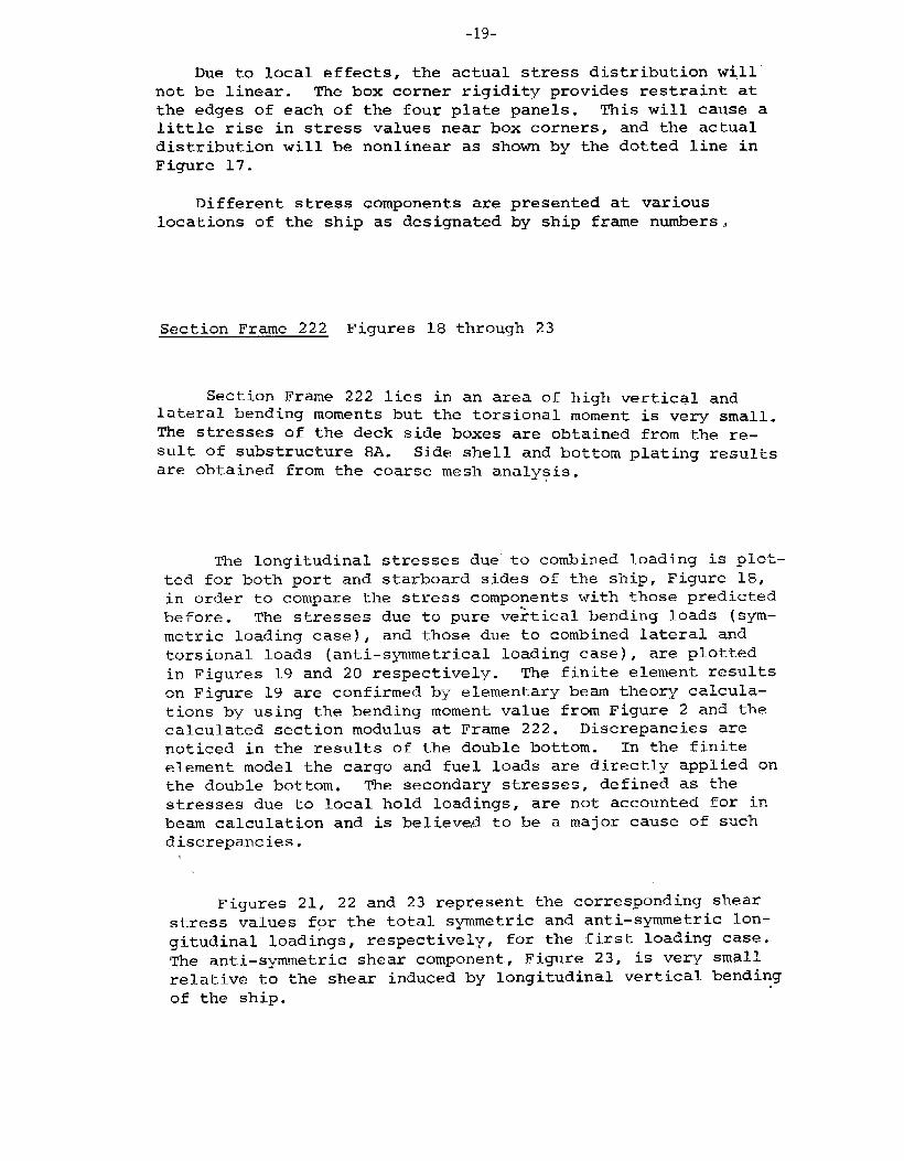
Section Frame 222 Figures 18 through 23
Section Frame 222 lies in an area of high vertical andlateral bending moments but the torsional moment is very small.
The stresses of the deck side boxes are obtained from the re-
sult of substructure 8A. Side shell and bottom plating resultsare obtained from the coarse mesh analysis.
The longitudinal stresses due’”to combined loading is plot-
ted for both port and starboard sides of the ship, Figure 18,
in order to compare the stress components with those predictedbefore. The stresses due to pure ve;tical bending loads (sym–
metric loading case) , and those due to combined lateral and
torsional loads (anti–symmetrical loading case), are plotted
in Figures 19 and 20 respectively. The finite element results
on Figure 19 are confirmed by elementary beam theory calcula–
tions by using the bending moment value from Figure 2 and thecalculated section modulus at Frame 222. Discrepancies are
noticed in the results of the double bottom. In the finite
element model the cargo and fuel loads are directly applied on
the double bottom. The secondary stresses, defined as the
stresses due to local hold loadings, are not accounted for in
beam calculation and is believed to be a major cause of suchdiscrepancies.
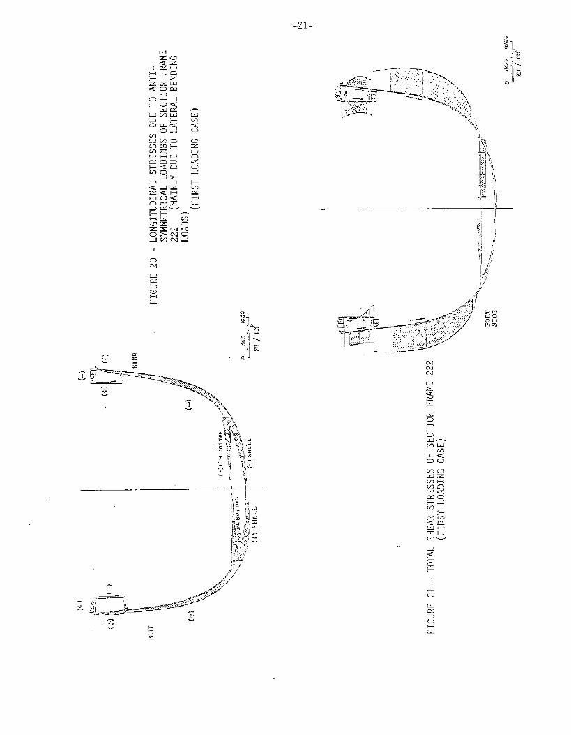
Figures 21, 22 and 23 represent the corresponding shear
stress values for the total symmetric and anti–symmetric lon–
gitudinal loadings, respectively, for the first loading case.
The anti–symmetric shear component, Figure 23, is very small
relative to the shear induced by longitudinal vertical bendingof the ship.
-20.
cc
.“-
<1
,+
-J
L
-7
.
c)w
L
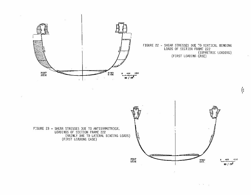
FIGURE 22 - SHEAR STRESSES DUE TO VERTICAL BENDINGLOADS OF SECTION FRAME 222
(SYMMETRIC(FIRsT LOADING CASE)
LOADING)
FIGURE 23 - SHEAR STRESSES DUE TO ANTISYMMETRICALLOADINGS OF SECTION FRAME 222
(MAINLY DuE TO LATERAL 13ENbING LOADS)(FIRST LOADING CASE)
PORTSIDE s!DE
-23-
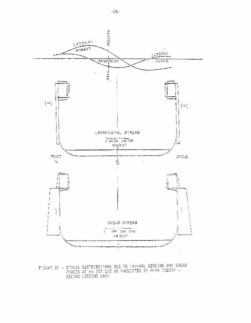
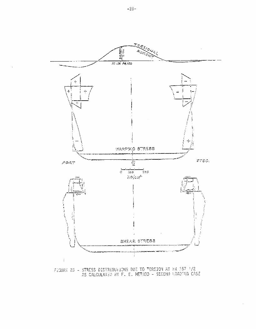
Section Frames 156-158. Figures 24, 25.
This section is subjected to “high values of combined moments
for the second loading case. The presented stresses are takenfrom fine mesh analysis of Model 3 (Fig. 11). They correspond
to the anti–symmetric component of the loadings. The stresses
are resolved into two components corresponding to lateral bend–
ing (Figure 24) and torsion (Figure 25) respectively. For pure
lateral bending (lateral shearing forces included), the stress
components are obtained by utilizing the elementary beam theory.
For pure torsion, the total computed values of warping andshear stresses for anti–symmetric loadings, less those shown in
Figure 24, are plotted in Figure 25. It is worth noting that
the distribution of torsional moment, as shown on the topof Figure 25, is arbitrarily referred to the base line of thevessel. This does not represent the true torsional momenton this section of the ship, hut. it serves the purpose of
demonstrating the procedure of interpretation of the stresses
without tackling the question of the exact location of the
shear center for this type of vessel.
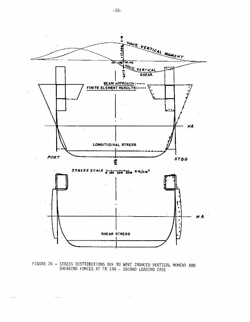
Sect.i,onFrames 188-192. Figure 25.
The presented stresses here are taken from ti.hefine meshanalysis of Model 4 (Fig. 11) running between frames 186 and194. The computed longitudinal and shear stresses in the
deck and side shell platings between Fr. 188-192 due to Wave
induced vertical moment and shearing force are plotted inFigure 26. The top diagram shows the distribution of loadingsalong the length of the vessel. It is interesting to note thatthe longitudinal stresses computed by means of both the finite
element techniques and the elementary beam theory are in goodagreement. This seems to confirm the validity of the beamapproach for calculating the hull girder bending stresses for
this type of vessel. The agreement is less for the shear stressdistributions, which may be attributed to local bending notcounted for in the beam approach.
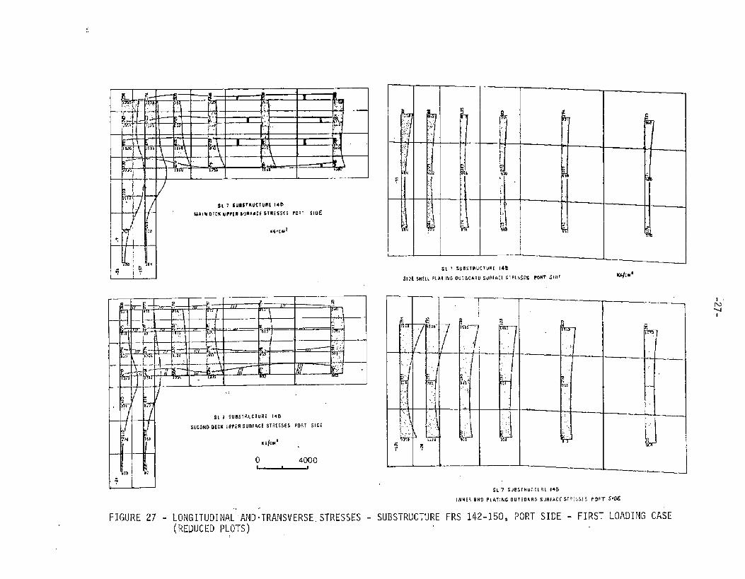
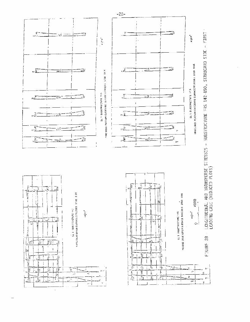
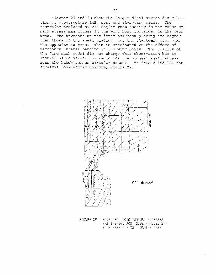
Deck Winq Box Forward to Engine Room Housinq Frames 142-150,
Figures 27 through 31.
~n the overall analysis of the ship, this part of the
structure is modelled as substructure 14B. In the subsequent
fine mesh analysis the portion from frames 142 to 146 is
remodeled as shown in Fig. 11 as Model 2.
-24-
I
,[
.26-
1
Y*
IBEAM APPROACH:— 1 I
EMENT RESULTS:===== “ ●
\
FINIT& EL-E _ ____ _
LONGITUDINAL STRESS
~OA? T sT&o
,
I
PSHEAR STREBS
L I
!
1●●.●● N“ A
FIGURE 26 - STRESS DISTRIBUTIONS DUE TO WAVE INDUCED VERTICAL MOMENT ANDSHEARING FORCES AT FR 190 - SECOND LOADING CASE
J!,L- , 4
.,
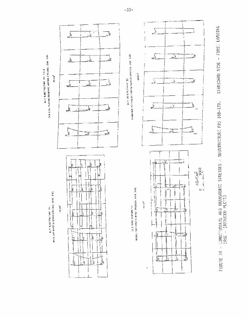
FIGURE 27 - LONGITUDINAL”AND.TRANSVERSE.(REDUCED PL~Ts)
I.;.,:.,,..,.,.,::,
u~
~
—-
‘4
/-
— ..
*
,q
L_
.—
R
$4“0
ISt 7 S.UBSTFILCTURE148
SIRISHIL1 PLATING OUT BOAR OSdR6hCI SIP(3S= POUT smfI@cd
:
j
w
._
-., ”
,.’.,.,
:.,
I,.,,,...,.,.m
G7
T- ..
E_1U13
.,, ;
?:a
SUBSTRUCTURE FRS 142-150, PORT SIDE - FIRST LOADING CASE
1
-28_
---—~-. -..
“-T-–T––.-..
II I I
i,,,:_. I —-.—.
I
1
-—
j--f ‘“-~4
S-’----L .F!ti: ‘ !.: /
1--—-.-–-l--—-~ “1-...——..”
+
L.—
__. —.
-;; --,-,---.
.—— .—
p -,—AL,-. .-
._. .— .——~----
!:
Y lk!_,_ .
--—._:: —..-.—” -- -1,
I
I._. .-— ——-“—. ~ —.
.,?r!l -—.-= .
..—.—,
I
.—, —:—————— ‘+ .“
—.—.——_ 1.— ..— J__ . .—.-— L.——a :———. —.——
r-–-r. .. ~.__J_, I
‘1
i --——1...-—.1...–—1 ----- .J_...~! -d[ ..__.J.~ ._~_J ..- -..! --- -—- -
—
-m, .--.30:
—
IIIII
I I II
II I
I,—- 4 ——— — ——.
1 II II
..- -.xI I I I
Tmi:I II
I ;1I I I
I ;1I I I ;1
—
III .—— .— - —
1 I; , I
—
I I .1
I I I 1
I
i--lm
u-
1
0m
IAcl?3usIL
-31-
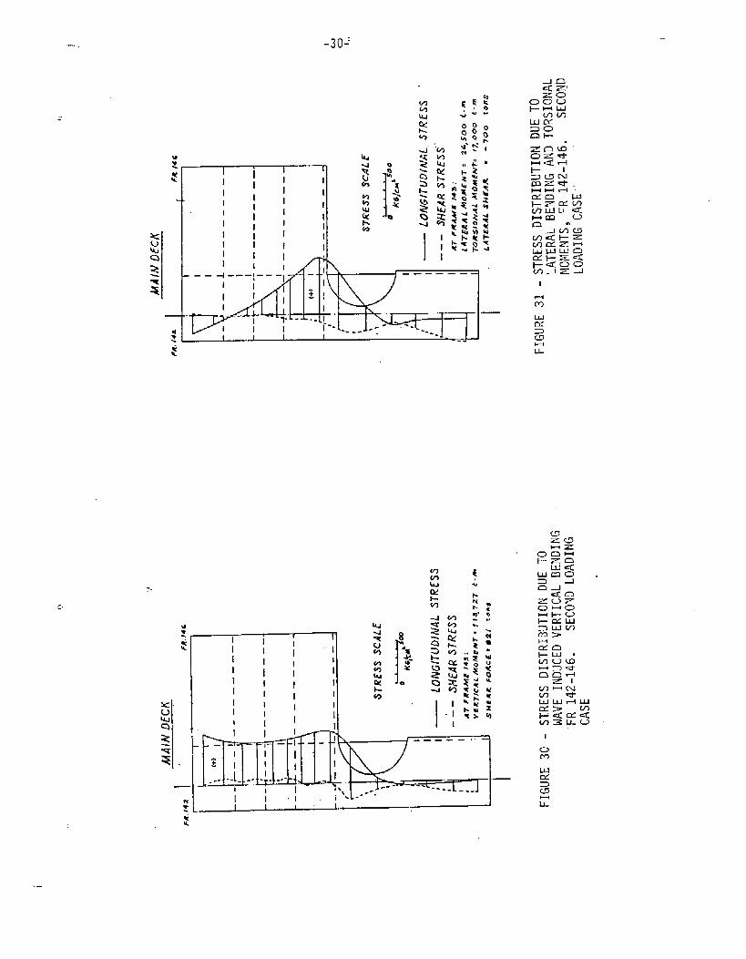
The computed longitudinal-and shear stress components
in the main deck plating near Fr. 143 corresponding to thewave–induced vertical bending are shown in Figure 30. The
stress components due to lateral bending and torsion areshown in Figure 31. It can be seen that the distr~%ution oflongitudinal stress components away from the hatch corner,
due to pure wave–induced vertical bending, may%e considered
uniform, (Fig. 30), and those corresponding to lateral bend-
ing and torsion may be represented by a straight line (Fig.31).—
Wincf Box-Transverse Box Connection at Fram& 178. Figures 32
through 40.
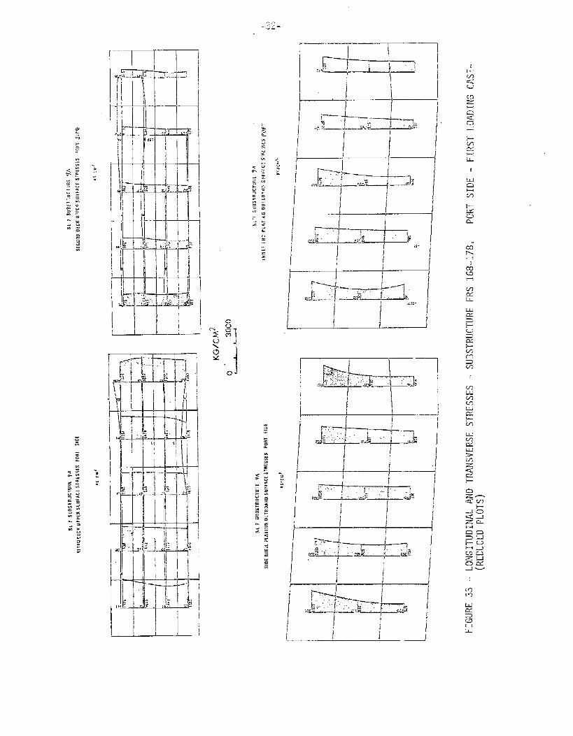
This portion of the deck structure is connected by twosub–structures, 9A and 9B, Figures 8, 10, and fine mesh model1, Fig. 11.
Figures 33 and 34 show the longitudinal stress distribu-tion of substructure 9A.
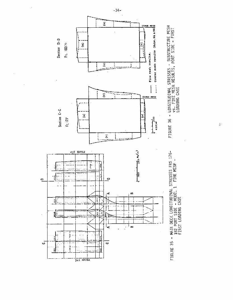
Figure 3!5 shows the fine mesh results of a part of the
deck structure running between ship frames 176 and 182. Thestress distribution an the deck is generally uniform at two
locations, namely, frames 177 and 180-1/2. The longitudinalstress distribution arou”nd the wing box cross section is plot–
ted, Figure 36, and compared with the stress results of sub-structure 9B at the same location. The stress pattern is aspredicted in Figure 17.
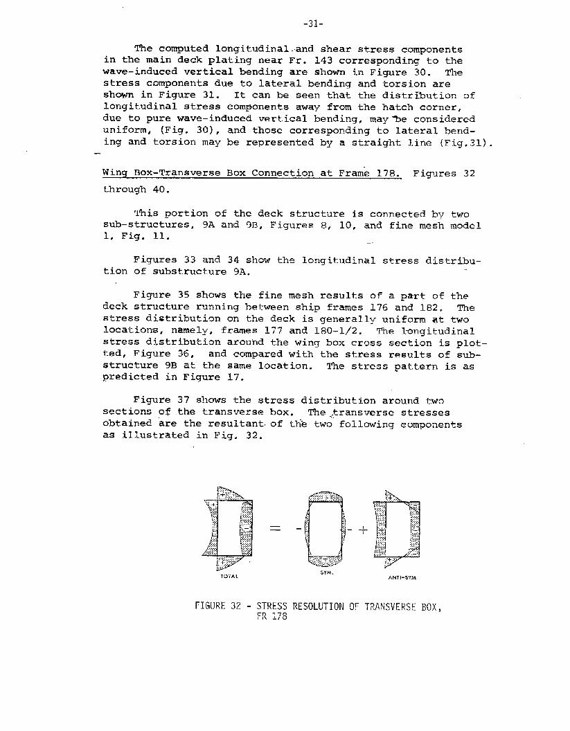
Figure 37 shows the stress distribution around two
sections of the transverse box. The .,$ransverse stressesobtained “are the resultant. of the two following components
as illustrated in Fig. 32.
FIGURE 32 - STRESS RESOLUTION OF TRANSVERSE HI)(,R? 178
-33-
,_,—-.— --- ——- 1
... .. .. ... . _.T---
I-~-l
rrr’l–
I _Ll
-34-
a
I 1!I
+II- aPTS
/----- )
1’I,
------ .-J
E~ ,1
- 1g~..-—- - -1‘
!
t
\I ‘- ‘1
“1u
L---- . 3x
0
~:I1
: +--– --- J----- ”--J
&---
?91IWb’M!I
.::. : .. ,.! .. .. . .. . .. . . i
- . . —.— .-. ———- -.., ;,..
s
“1 :
...- :.- .— f -
:,:,,,,,,.,. .. ,, . .,. .......... ,..-’.’ ,:
-: .Y. ----- - ,.
. ..:
- : : :. .,.:. ._ :;- .-.. ,: : ..:-:...:: ., . . .. . . . ;- ._—
-— .4
...
m : :; ,,:
.
g .....~ .- .
——— ...” —- .——. —
9LT Iwtyd
.4
1< ,Im
. .
1
wm
IL
r-l
1-WJ
1
u-)m
F-1I-L
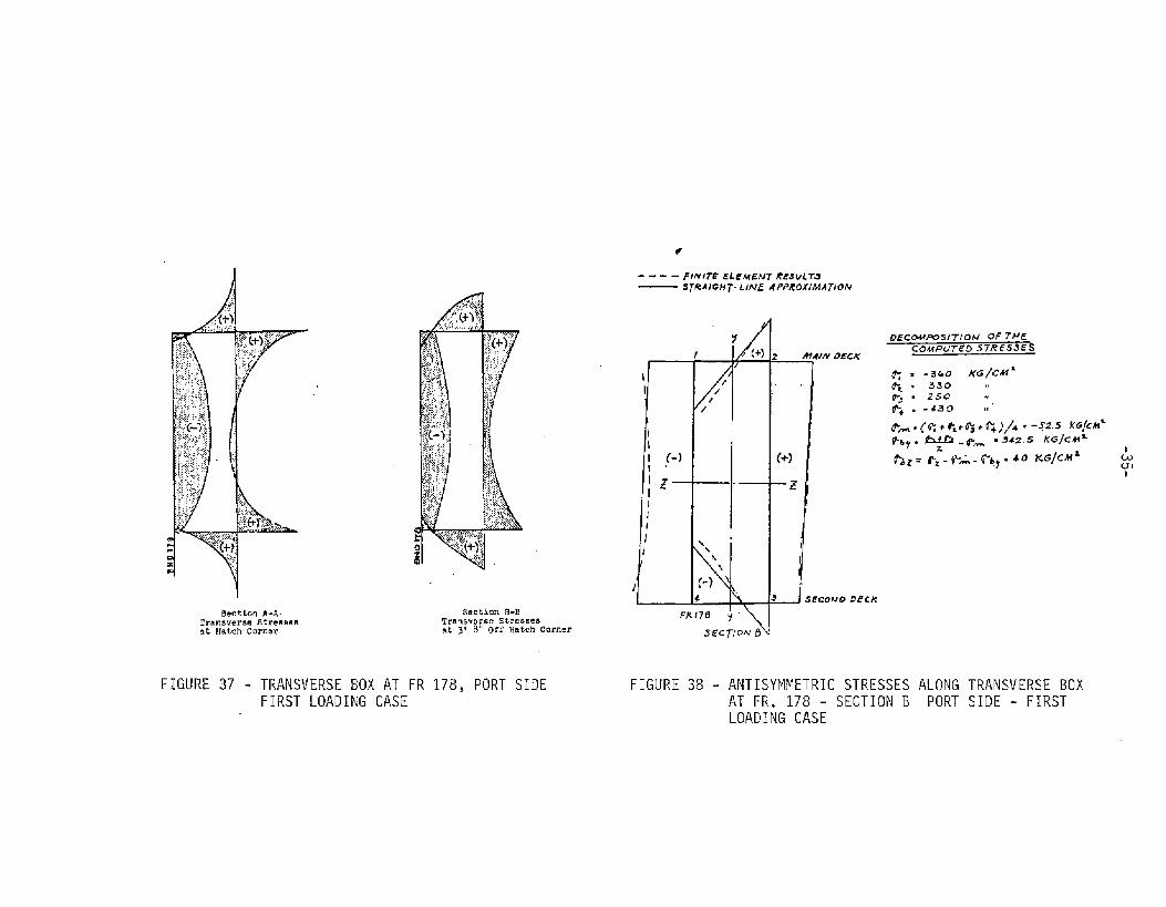
Section A-A.Transverse Stre6eesat Hatch Corner
Section B-BTransverse Stre6Besat 3( 8“ Off Hatch Corner
FIGURE 37 - TRANSVERSE BOX AT FR 178, PORT SIDEFIRST LOADING CASE
QECMFOSITIOff OFT.4E
M4/fv OECKCOMPUTEO 57RES3ES
FIGURE 38 - ANTISYMMETRIC STRESSES ALONG TRANSVERSE BOXAT FR. 178 - SECTION B PORT SIDE - FIRSTLOADING CASE
CLU1I
.
[ —— --— —-”-’—. .-%
KG/CM2
mid
TTI
1i I L v v v v
LONGITUD-Sti~L-ANEITRANSVERSE STRESSES - SUBSTRUCTURE FRS 226-235 PORT SIDE -
/“L &
/
%r-%r
zfirL
/“kAA-
?-
/
&-
%E
FIRST LOADING CASE
c!.)mI
(REDucED PLoTs)
-3Y-
‘$
:
l--!
Tn connection wit,h the proposed so called “stress” gages—
~~ FT. 186 1./4, port and starboard, (Ref. 9)0 the peak-to–peak
vert$cal and lateral “bending skresses which are in the order of
1,400 Kg!cm 2 (20,000 psi) and 900 Kg/cm2 (13,000 psi], respec-
tively, might be expected if the vessel would experience severe
seas during the instrumentation period. I-L is expected that no
significant warping stress will Toe recorde~ at this section
because it is so close tio tble zero–twist point tif the vessel.
At frameHowever, fromto similarityframe 226, it
same.
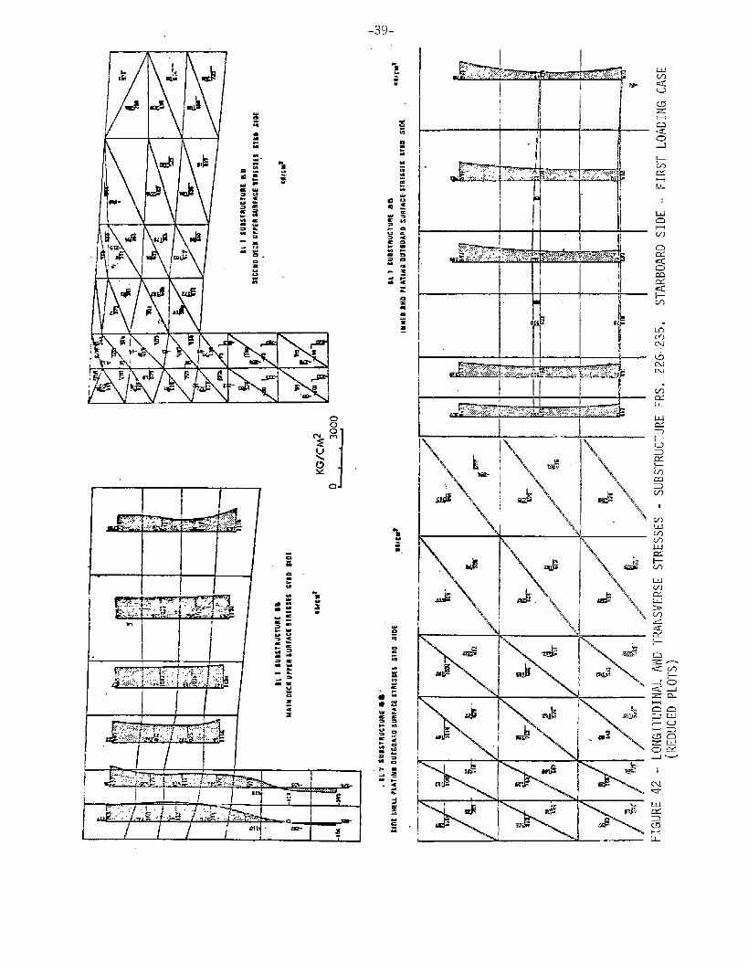
There is~ocation, frames 73–80, ~94-196-and 242-244. Since the second
hatch f9rward of the engine room experienced the maximum hatch
diagonal distortion, a portion of the transverse box frames
17’8-190 is included in fine mesh, model 1. The results are
discussed previously, Figures 36 through 40.
259. a very coarse grid is used in this area.
&he coarse mesh results, Figures 43, 44, and duein structural configuration to that location at
is expected that the stress pattern will be the
no detail qrid employed in the transverse box
FIGURE 43 - COARSE MESH DECK STRESSES (KG/CM2), STARBOARD SIDE, FIRSTLOADING CASE
I
II
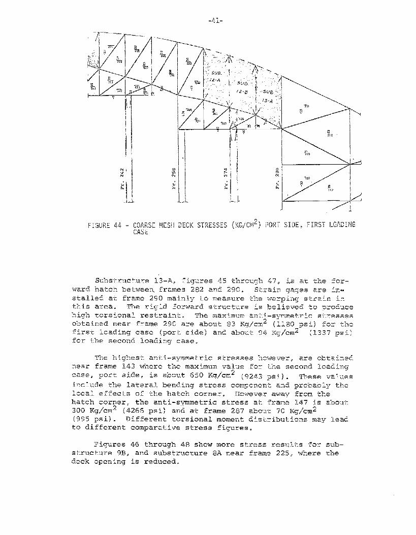
FIGURE 4.4- COARSE MESH DECK STRESSES (KG/CMz) PORT SIDE, FIRST LOADINGCASE
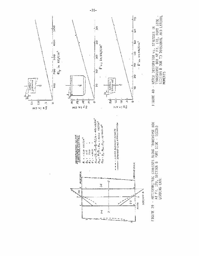
The ‘nifghest anti–symmetric skresse~ ?ncweverp are obtainednear frame 143 where the maximum value for the second loading
case, port. sided is abo+~t EJ50 Kq/cm.2 (q~~.~ ~=~) ~ These va?uesinclude the lateral. bending stress componep.’c and probably the
local effects of the hatch corner. 130we-ver away frQm &hJehatch corner, the anti-symnetric stress ati frame 147 is about300 Kq/cm2 (4266 psi) and at frame 287 about 70 Kg/mn~
(995 psi). Different torsional moment distributions may leadto different comparative stress figures.

-42-
It is worth noting that the substructu.ring of the deck lo–
cations was based on early proposed strain gage placement. How–
ever, in a later stage of the SL–7 instrumentation prqram and
after the computer calculations were completed, more gages were
assigned in locations not covered by substructures or fine
mesh models. (Compare instrumentation plan (7) witih sub-
structure layout, Figure 8, and fine mesh models. Figure 11) .
—,-” .———. -—
I———.
4.. —
—. .—
ZE!Z ,?3-
EEiEal
...—-... —....—
—..—. u
1-
_J._L_L- I l\
b—
2
.r’.m4
C&r-l
mc=L
w)mlVIu-!L.!CLF-W)
ri-m
-45-1
-— —... —
R-
Q_
I
$1 1 SUSSTRIJCTURE @A
MA IHDISS UPPER SLIRFACE STRISSES STBD $10[
l——————_L_—l 1,
&i
KG/Ch42o 3000L&
S1 7 S!J8STRUCTUBE 8A
l!SHiFl BHII PLATING IJIITBDARO SUFIFAC&STBESSIS ST8D SIDi EL/cd
!
-Lm
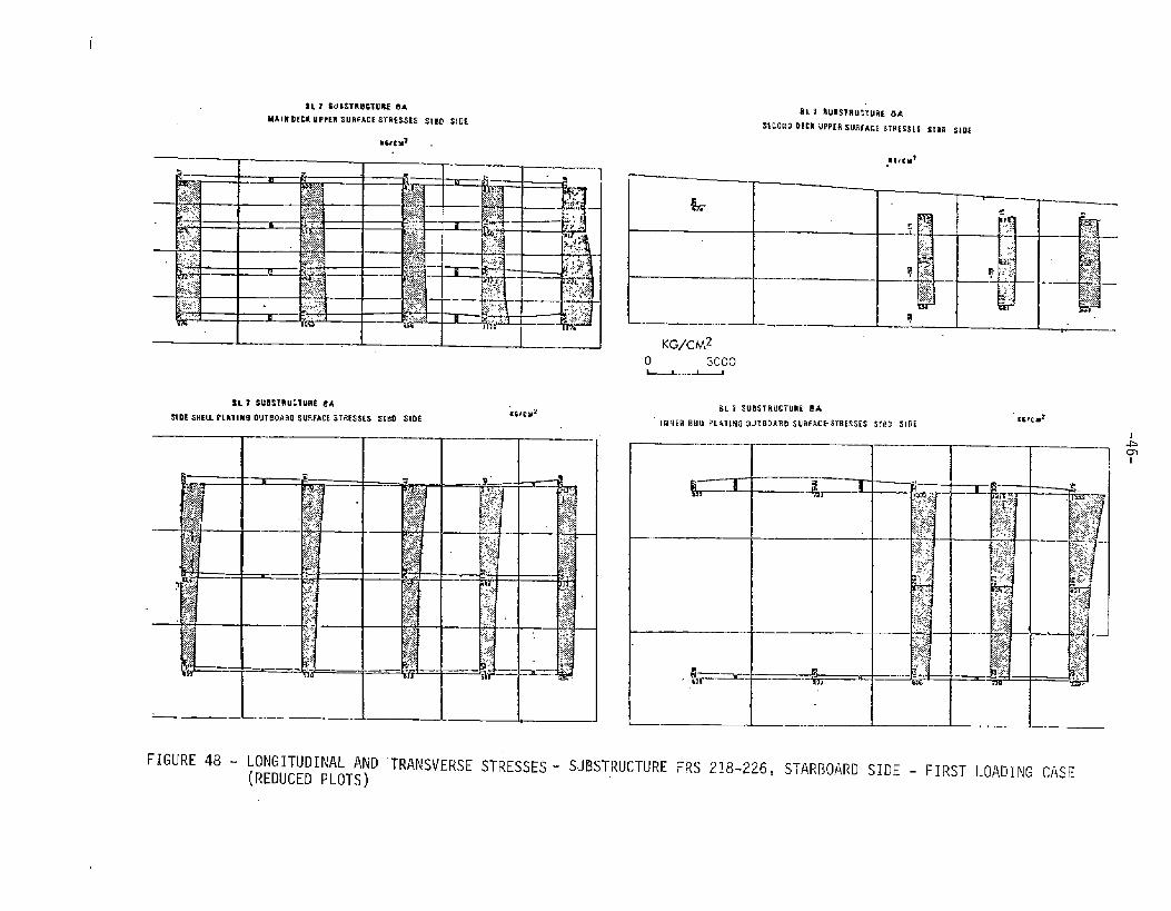
FIGURE 48 - LONGITUDINAL AND “TRANsVER$jEsTRESSES - SUBSTRUCTURE FRS .218-226, STAR130ARD SIDE - FIRST LOADING CASE(REDUCED PLOTS)
-47-
CHAPTER IV
CONCLUSIONS AND COMMENTS
1. Local deformation due to the non–prismatic nature of thestructure and the deck openings can cause considerable
increase in the total stress level as observed in theinner bulkhead plating of substructure 14–B, Figure 27.
2. A relationship between hatch distortion and the trans-verse box stress values is introduced. The finite elementstress distribution in this area suggested the linearityof the stress pattern. This approach is to be verified bythe experimental results when available.
3. The Navier Beam Hypothesis as applied to the open deck box
girder appears to be adequate in predicting the primary
response of the container ship under vertical bending
moments.
4. Interpretations of the stress results at the locations ofsome strain gages on the “S@a-Land M~Lean” are made. Earlyoutput .of the finite element results had helped in the
determination of the final location of some gages.
5. For the first loading case, the Following noteworthy valueshave been ’observed from the finite element calculations:
a.
b.
c.
d.
e.
Zero twisting angle is found near rn~ilslnip frame 190.
The maximum diagonal hatch distortion amounted to2.4 ems. (0.94 inch), in the second hatch forward ofthe engine room compartment.
In deck areas where substructures were not employed,
the maximum longitudinal stresses attained are about
1400 Kg/cm 2 (19,900 psi) on the port side and about1300 Kg/cm 2 (18,48’6 psi) on the; starboard side.
On the side shell platings the maximum longitudinalstresses obtained are in the neighborhood of 2000
Kg/cm2 (28,440 psi) between frames 210 and 242.
A particular region of high stresses is found in themain deck forward of the engine room housing, frames
142-144. The maximum longitudinal stress at frame 143is 2750 Kg/’cm2 (39,105 psi).
-48-
REFERENCES
1.
2.
3.
4.
5.
6.
7.
Stiansen, S. G., Elbatouti, A., “’Finite Element Analysis of
Container Ships”, Symposium on the Computer in Finite Element
Analysis of Ship Structures, Tucson, Arizona, March, 1972.
0. Grim, “SL-7 Containership. Calculations of the Vertical,Horizontal and Torsional Loads Occurring in Waves”, 1970,
for J. J. Henry Co., Inc.
H. A.” Kamel, et al. “The Computer in Ship Structure Design”,
ONR International S~posium on Numerical and Computer Methods
in Structural Mechanics. The University of Illinois, Sep-
tember 1971,
H. A. Kamel,
1, 2, AugustArizona.
H. A. Kamel,
Urbana.
A. Elbatouti, “DAISY Engineers Manual”, Volumes
1970, American Bureau of Shipping, University of
A. Miller, “DAISY, Programmers’ Manual”, May 1972,
American Bureau of Shipping, University of Arizona.
D. Liu, “SHIPMOM”, “EXAM”, “EXPLOT”, “LOADER”, Engineering
Manuals, August 1970, American Bureau of Shipping, University
of Arizona.
Design and Installation of a Ship ResponseSystem Aboard the SL–7 Class S.S. Sea–LandMaterials Research, E-1395 (b).
ACKNOWLEDGEMENT
The authors are indebted to Sea Landproviding all the information on the ship
analysis.
The authors also wish to acknowledge
InstrumentationMcLean. Teledyne
Services, Inc.subject to the
the efforts of
for
IX. Hussein Kamel, Professor, Aerospace and Mechanical En–
gineering Department, University of Arizona, who is the author
of the DAISY computer program.
Appreciation is also extended to many
Research and Development Department of the
Shipping for their efforts and assistance.
members of the
American Bureau of
.
S?curit\- Class ltlratlon
DOCUMENT CONTROL DATA- R&D,S,. c,, rti f,. <18.. s,{; <.!,.0. 0{ [,![?, body of ahxtra<. [ i,, IL! indcxi,>b: ,jr>notaiion .>.,1 he et)!eted wf]en (IIC overall report ;S rl;; s.zl[rd)
ORIGINATINGACTIW’TY([corporateaulbor) 2a. REPORTSECURITYCLA551F!CAT10NUnclassified
American Bureau of Shipping 2b. GROUP
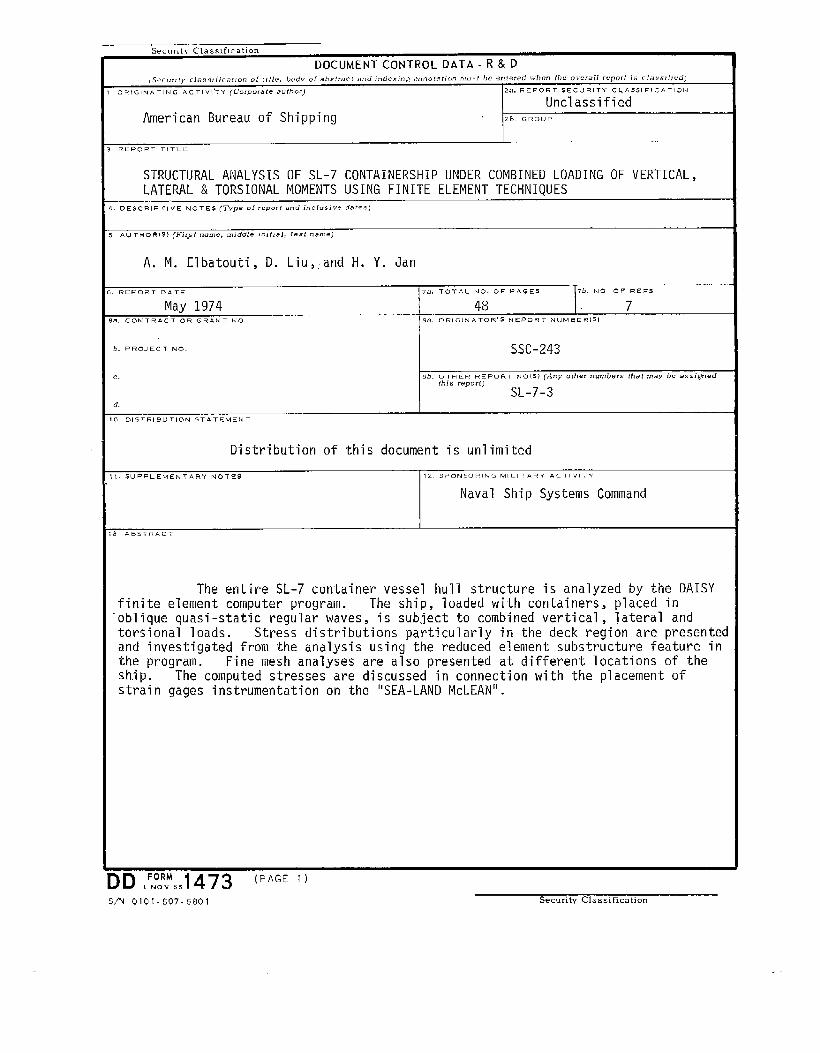
REPORTTITLE
STRUCTURAL ANALYSIS OF SL-7 CONTAINERSHIP UNDER COMBINED LOADING OF VERTICAL,LATERAL & TORSIONAL MOMENTS USING FINITE ELEMENT TECHNIQUES
DE SCRIP HUE NOTES (TYPe 01 ,CPO,I and in C! LISi V? dsro$)
ALI~MORtSI (Fir+t ritim~, middle inilial, last rIame)
A. M. Elbatouti, D. Liu,,and H. Y. Jan
REPORT DATE 7ii. TOTAL NO. OF PAGES Tb. NO OF REF5
May 1974 48 7.,CONTRACT Oa GRANT NO. w. 0RIGINATOR,5 MEPORT NUMBERi51
b. PROJECT NO, SSC-243
c, ~b. OTHER REPORT Hots) (Any other numbers (Ilai ,mey hc as=ignedthis reporf)
SL-7-3d,
0 DISTRIBUTION STATEMENT
Distribution of this document is unlimited
1. SUPPLEMENTARY NOTEs
3 AB5TRACT
12. SPONSORING MILITARY ACTIVITY
Naval Ship Systems Command
The entire SL-7 container vessel hull structure is analyzed by the DAISYfinite element computer program. The ship, loaded with containers, placed in“oblique quasi-static regular waves, is subject to combined vertical, lateral andtorsional loads. Stress distributions particularly in the deck region are presentedand investigated from the analysis using the reduced element substructure feature inthe program. Fine mesh analyses are also presented at different locations of theship. The computed stresses are discussed in connection with the placement ofstrain gages instrumentation on the “SEA-LAND McLEAI!”.
lD!iWe,1473 (PAGE’)S/N 0101-807-6801 Security Classification
Securltv Class ltlcatlon
4KEY WORDS
LINK A
ROLE WT
Ll
ROLE
0
WT
(PAGE 2) Security Classification
LINK C
ROLE WT
—
Nationa
SHIP RESEARCH COMMITTEEMaritime Transportation Research BoardAcademy of Sciences-National Research Council
The Ship Research Committee has technical cognizance of the interagencyShip Structure Committee’s research program:
PROF. J. E. GOLDBERG, Chairman, $c~o02 of Cioil Engineemkg, Puzdue Univerw<ty
PROF. R, W. CLOUGH, Prof. o.fCivil EnqineeFinq.Unive-rs{tziof Cal{fomiaDR. S. R.MR. G. E.MR. W. W.MR. D. P.MR. R. C.MR. H. S.
HELLER, Jr., ~’ma~, Civi2 &“Mech.E~~. Dept., y~~ >atholieUniv. of AmericaKAMPSCHAEFER, Jr., Manager, TechnicalSawxk%, ARMCO Ske~2 Corpo~ationOF”FNER, ConsultingEngineer,San FranciscoROSEMAN, Chief Naval Areh{tect,Hgdronautics,Jnc.STRASSER, Di?ectorofl%smrch, NeuportNezx Sh<pbuiZding& DFy Dock Co.TOWNSEND, Vice President,(7,S.Sa2vaqeAssociation.Inc.
DR. S. YUKAWA, ConsultingEngineer: GeneraZElzctrie Company”AR. R. W. RUMKE, Executive Secretary, Ship Research Committee
Advisory Group I, “Ship Response and Load Criteria”, prepared the projectprospectus and evaluated ”the proposals for this project:
MR. D. P. ROSEMAN, Chairman, Chief Naval A~ehiteck,Hydronautics,Inc.PROF. J. L. BOGDANOFF, School of Aeronaut~cs& A.st~onautiics,Purdue Un<vemityMR. M. D. BURKHART, Head, Marine Seiwzee Affairs, Off& of Oc~anog~apherof the NavyDR. C. CHRYSSOSTOMIDIS, Asst. Prof. ofN~al ArchiteckWe, Mass. Inst. of TechnologyMR. C. W. COWARD, HuZZ TechnicalManage?, NQwportNeus Shipbuilding& Dry Dock Co.DR.. R:,GLASFELD, Naval Arelzit@ct,G~neralDynamicsCo~porationDR. J.’E. HALKYARD, Senior ocean EngineaY,Kennecott ExplO~at~On, Inc.
DR. N. H. JASPER, Techn{ca2Director,Naval Coasta2SystemsLaboratoryMR. R. G. KLINE, Assoc. Research Consultant,U.S. S&eeZ CorporationPROF. J, LANDWEBER, Instituteof Hydraulic.Research,The Universityof IowaDR. M, K. OCHI, Researeh Scienkisk, Nava2 Ship Research & DevelopmentCente~PROF. J, C. SAMUELS, Dept. of EzectricazEngineering,Howard UniversityPROF. M. SHINOZUKA, Dept. of Ciz)ilEngineering& fig. Mechan{cs,CoZumbiaUnivasityPROF. R. A. YAGLE, Ppof. of Nava~ Architecture,
The SL-7 Program Advisory Committeeguidance, and reviewed the project reports with
Universityof Michigan
provided the liaison technicalthe investigator:
Neupo~tNeus Shipbuilding& Dry Dock Co. IMR. R. C. STRASSER, Chairman, Dip. of Research=MR. E. R. ASHEY, Ass-t. for Advanced Technology,Nav;l Ship Engin~eringCentmPROF. E. V. LEWIS, Directorof f(esearch,Webb Instituteof NavaZ ArchitectureMR. J. H. ROBINSON, Staff Navaz Architect,Naval Ship Rese~ch & DevezopmentiCentie~MR. D. P. ROSEMAN, Chief”flavalA~chitect,Hydronautics,Inc.PROF. R. A. YAGLE, Prof. of Naval A~chitecture,Unive~sityoftvl+zigan
.
.
SHIP STRUCTURE COMMITTEE PUBLICATIONS
SSC-234,
SSC-235,
SSC-236,
SSC-237,
SSC-238,
SSC-239,
SSC-240,
SSC-241,
SSC-242,
SL-7-1 ,
SL-7-2,
SL-7-3,
These documents are distributed by the National TechnicalInformation Sewiee, Springfield, Vu. 22151. These doc-uments have been announced in the Clearinghouse jouzwzalU.S. Government Research & Development Repo~tz (USGRDR)under the indicated AD numbers.
@vaZuatiion-ofMethods for .Ex&apolation of Ship Bending Stress Databy D, Hoffman, R. van Hooff, and E. V. Lewis. 1972. AD 753224
Effect of Temperature and Strain Upon Ship Steels by R. L. Rothmanand R. E. Monroe. 1973. AD 768891
A Method for Digitizing, prepa~ing and Using Library Tapes of ShipSt~ess and Environment Data by il. E. Johnson, Jr., d. Il. Flaherty,and I. J. Walters. 1973. AD 767388
Computer Progrwns fop the Digitizing and Using of Lib~a?y Tapes ofShip Stress and Environment Data by A. E. Johnson, Jr.,J. A. Flaherty, and I. J. Walters. 1973. AD 768863
Design and Installation of a Ship Response Instm.mentation SystemAboard the SL-7 CLass Containe~ship S.S. SEA-LAND McLEAN byR. A. Fain. 1974.
Wave Loads in a Model of the SL-7 ContainershipRunning at ObliqueHeadings in Regular Waves by J. F. Dalzell and M. J. Chiocco. lg74.
Load C~itez+a fop Sh{p Structural Design by E. V. Lewis, R. vanHooff, D. Hoffman, R. B. Zubaly, and W. M. Maclean. 1973. AD 767389.
Thermoelastie Model SLudies of C~yogenic Tanke? Structu~es byH. Becker and A. Colao. 1973. AD 771217
Fast Fractu?e Resistance and C~ack Arrest in St~uetupaZ Steels byG. T. Hahn, R. G. Hoagland, M. F. Kanninen, A. R. Rosenfield andR. Sejnoha. 1973. AD 775018
SL-7 PUBLICATIONS TO DATE
(SSC-238) - Design and Installation ofa Ship Response InstrumentationSystem Aboard the SL-7 CZass Containership S.S. SEA-LAflDMcLEAN byR. A...Fain. 1974.
(SSC-239) - Wave Loads in a Modal of the SL-7 Containership Runningat Oblique Headings in Regular Waves by J. F. Dalzell andM. J. Chiocco. 1974.
(SSC-243) - St~uctuyaZ Anulysis of SL-7 Containership Under CombinedLoading of Vertical, Lateral and Torsional Moments Using FiniteElement l’eehniquesby A. M. Elbatouti, D. Litiand H. Y. Jan. ~974”
- — —.. ..———..——.—. ..


![Linear Guideways - aratron.se with VDI 2230. Table 2.1 Static structural safety Loading f SL; f SM [min.] Normal loading 1.25 – 3.00 With impact and vibration 3.00 – 5.00 1) ...](https://static.fdocuments.in/doc/165x107/5b0980a37f8b9a51508d60f5/linear-guideways-with-vdi-2230-table-21-static-structural-safety-loading-f-sl.jpg)
