Container Unloading using Robotized...
80
Container Unloading using Robotized Palletizing – A study for automation of Container Unloading at Elgiganten’s central warehouse Master of Science Thesis in the Production Engineering Programme PATRIK GUSTAFSSON-SKOGLUND KARL SÖDERENG Department of Product and Production Development Division of Production Systems CHALMERS UNIVERSITY OF TECHNOLOGY Gothenburg, Sweden, 2012
Transcript of Container Unloading using Robotized...

Container Unloading using Robotized Palletizing – A study for automation of Container Unloading at Elgiganten’s
central warehouse
Master of Science Thesis in the Production Engineering Programme
PATRIK GUSTAFSSON-SKOGLUND
KARL SÖDERENG
Department of Product and Production Development
Division of Production Systems
CHALMERS UNIVERSITY OF TECHNOLOGY
Gothenburg, Sweden, 2012
Container Unloading using Robotized Palletizing
- A study for automation of Container Unloading at Elgiganten’s central warehouse
PATRIK GUSTAFSSON-SKOGLUND
KARL SÖDERENG © PATRIK GUSTAFSSON-SKOGLUND & KARL SÖDERENG, 2012
Master of Science Thesis Work
Department of Product and Production Development
Chalmers University of Technology
SE-412 96 Gothenburg
Sweden
Telephone: + 46 (0)31-772 1000
Front cover:
Own Picture
Caption:
Robotized Palletizing
Chalmers Reproservice
Gothenburg, Sweden, 2012
Preface
This Master of Science thesis work was performed during the spring term of 2012 at the
department of Product and Production Development at Chalmers University of Technology in
Gothenburg. The thesis covered 30 credits and is the final examination in the master program,
Production Engineering. This project is carried out in collaboration with Front Automation
AB in Jönköping and one-third of the time has been spent at the site and the rest at Chalmers
in Gothenburg.
We want to thank individuals and organisations who have helped us during this project. First
of all, we would like to thank Front Automation AB, who has given us the opportunity to
perform our master thesis within industrial robotics and for always supporting us with the
information needed. We are very thankful for the coaching and guidance provided by our
supervisor Jonatan Berglund during the project. Also, we want to thank the examiner, Rolf
Berlin, and robot expert, Per Nyqvist, for their knowledge input to specific parts of the
project.
Many thanks are also directed to Johan Olsson at Tepro Machine & Pac Systems AB, Jesper
Lundstedt at Robotics Division ABB AB, Cuong Lien Elgiganten AB, Andreas Lövgren at
DHL Exel Supply Chain AB and Eskil Laago at IKEA Svenska AB.
Gothenburg, Sweden, May 2012
_______________________ _______________
Patrik Gustafsson-Skoglund Karl Södereng
Abstract
As the globalisation increases and many companies are locating their production in low cost
countries, effective logistics becomes more and more important. The automation of
distribution centres and central warehouses is a vital topic today. A problematic as well as
labour intensive field at central warehouses is the container unloading procedure, which today
still often consists of manual work. The container unloading procedure consists of unloading
containers, filled with cartons of varying sizes and weights, and placing these in a
predetermined pattern on a pallet. To reduce the risk of work related injuries automation is an
alternative considered by more and more companies.
The case studied is Elgiganten’s central warehouse. Elgiganten is included in the Norwegian
cooperate group, Elkjop, which is an actor within the consumer electronics business. This
giant warehouse covers 100 000 square meters and serves all Elkjop stores in the Nordic
region. The purpose of this study was to evaluate the potential of using robotized palletizing
and suitable aids for the application Container Unloading at Elgiganten’s central warehouse.
This study included an evaluation of the recently developed software, Palletizing PowerPac,
which is a software dedicated for palletizing procedures. Analyses of the work environment
with regards to ergonomics were made with the purpose to investigate how this could be
improved. During the project a suitable gripper has been selected for the large variety of
cartons present at Elgiganten.
The results from this study showed that robotized palletizing using Palletizing PowerPac was
feasible. With the selected gripper, cartons with weights less than 30 kg and side lengths of
600 mm or less should be handled. Two solutions, ParceLift and Empticon, were evaluated to
be most appropriate for Elgiganten to use in combination with robotized palletizing for the
application Container Unloading. The major advantage of introducing aids and robotized
palletizing was found to be the reduced risk of musculoskeletal disorders.
Keywords: Robotized palletizing, Vacuum gripping, Palletizing PowerPac, Container
unloading

Table of Contents
1 Introduction ........................................................................................................................ 1
Background .................................................................................................................. 1 1.1
Problem Formulation ................................................................................................... 2 1.2
Purpose ........................................................................................................................ 3 1.3
Delimitations ............................................................................................................... 3 1.4
Specification of Question Formulation ........................................................................ 3 1.5
Report Disposition ....................................................................................................... 4 1.6
2 Methodology ...................................................................................................................... 5
Collection of Data ........................................................................................................ 5 2.1
Evaluation of Palletizing PowerPac ............................................................................ 5 2.2
Verification at Front Automation ................................................................................ 5 2.3
Analyses of Proposed Solutions .................................................................................. 7 2.4
3 Theoretical Framework ...................................................................................................... 8
Industry Characteristics ............................................................................................... 8 3.1
3.1.1 Container Transportation ...................................................................................... 8
3.1.2 Pallets and Palletizing .......................................................................................... 9
Industrial Robots .......................................................................................................... 9 3.2
3.2.1 Robot Programming ........................................................................................... 12
3.2.2 Palletizing PowerPac .......................................................................................... 13
Gripping Technologies .............................................................................................. 16 3.3
3.3.1 Classification of Grippers ................................................................................... 16
3.3.2 Requirements on a Gripper ................................................................................ 18
3.3.3 Vacuum Gripping ............................................................................................... 18
3.3.4 Vacuum Theory .................................................................................................. 19
Identification Systems ............................................................................................... 20 3.4
Ergonomics ................................................................................................................ 21 3.5
3.5.1 REBA ................................................................................................................. 21
3.5.2 NIOSH ................................................................................................................ 22
3.5.3 JACK .................................................................................................................. 23
Systematic Evaluation ............................................................................................... 24 3.6
Existing Solutions ...................................................................................................... 24 3.7
3.7.1 ParceLift ............................................................................................................. 24
3.7.2 Empticon ............................................................................................................ 25
3.7.3 ParcelRobot ........................................................................................................ 26
3.7.4 Random Box Mover ........................................................................................... 27
3.7.5 TEUN ................................................................................................................. 29
3.7.6 Copal .................................................................................................................. 29
3.7.7 IKEA .................................................................................................................. 30
3.7.8 Attends ............................................................................................................... 30
4 Analysis ............................................................................................................................ 31
Work Procedure at Elgiganten ................................................................................... 31 4.1
Palletizing PowerPac ................................................................................................. 32 4.2
4.2.1 Strong points ...................................................................................................... 32
4.2.2 Deficiencies and Teething Problems .................................................................. 33
4.2.3 Applicability in the case Elgiganten ................................................................... 37
Key Factors for a Solution at Elgiganten ................................................................... 38 4.3
4.3.1 Carton Dimensions and Characteristics ............................................................. 38
4.3.2 Cycle Time ......................................................................................................... 41
4.3.3 Gripper Design ................................................................................................... 42
4.3.4 Capacity Level .................................................................................................... 46
Evaluation of Solutions ............................................................................................. 47 4.4
4.4.1 Analysis of Existing Solutions ........................................................................... 47
4.4.2 Pugh Matrix ........................................................................................................ 49
4.4.3 Kesselring ........................................................................................................... 50
Proposed Solutions .................................................................................................... 50 4.5
4.5.1 Proposition A: ParceLift .................................................................................... 50
4.5.2 Proposition B: Empticon .................................................................................... 51
4.5.3 Robotized Palletizing ......................................................................................... 51
5 Discussion ........................................................................................................................ 53
6 Conclusion ........................................................................................................................ 55
References ................................................................................................................................ 56
Appendix – Ergonomics .............................................................................................................. I

Abbreviations
ISO International Organisation for Standardisation
NIOSH The National Institute for Occupational Safety and Health
PzPP Palletizing PowerPac
REBA Rapid Entire Body Assessment
TEU Twenty-foot equivalent unit
TOF Time Of Flight

Container Unloading using Robotized Palletizing Introduction
1
1 Introduction
In times of increased globalization the transportation and demand for automatized logistic
solutions also increase. Many goods are today transported in containers, by ships, trains and
trucks. The management of loading and unloading goods from containers is carried out in
different ways depending on type of goods and distance. If the goods have to be transported a
far distance the filling degree is important, which in many cases make the loading and
unloading process problematic.
The application ”Container Unloading” is common amongst various distribution centres,
where goods are reloaded for further distribution to different department stores. The work
procedure consists of unloading containers, filled with cartons of varying sizes and weights,
and placing these in a predetermined pattern on a pallet for further distribution by truck.
This report starts with a background to the project and the foreseen difficulties that have to be
taken into consideration. In the introduction part the purpose and delimitations of the project
is presented.
Background 1.1
The case studied is Elgiganten’s central warehouse. Elgiganten is included in the Norwegian
cooperate group, Elkjop, which in turn is owned by the British consumer electronics’
company, DSG International. This giant warehouse covers 100 000 square meters and serves
all Elkjop stores in the Nordic region [1]. Consumer electronic is a tough business, where the
actors always compete about having the lowest prices. Because of struggling with keeping
low prices the profit margin per unit will decrease. Another problem Elgiganten has to handle
is the high absence of employees due to heavy lifts and stressed work environment [2]. This
problem motivates an automated solution for the manual work of unloading containers.
Elgiganten has seasonal variation in demand, which affects the requirements of the central
warehouse. At the autumn there is a peak in demand, which in turn affects the central
warehouse a couple of months earlier. There is also a peak in the spring when all the grills are
arriving for the summer. During other months of the year the demand is much lower, which of
course affects the proposed solutions.
This study was also performed in collaboration with Front Automation. Front Automation is a
Preferred Partner by ABB Robotics. This means that the work is performed in close
collaboration with ABB to develop and supply system solutions where the ABB products are
used and integrated. Within the field picking, packing and palletizing Front Automation is the
preferred system integrator in Sweden by ABB.
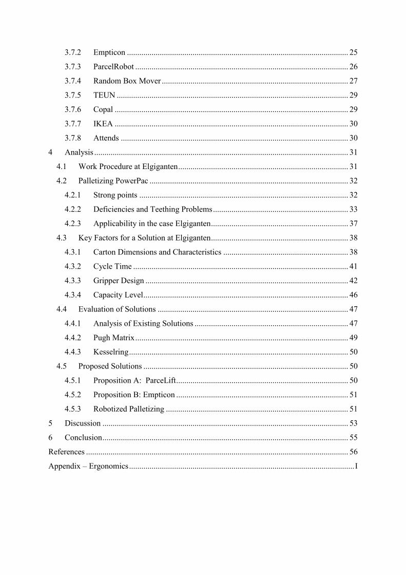
At Elgiganten, the application Container Unloading is divided into two stages, referred to as
Stage One and Stage Two. Stage One consists of unloading containers filled with cartons, see
number one in Figure 1. Number two in Figure 1 is the telescopic conveyor belt, which
transports the cartons from the container to the next stage. Stage Two consists of placing these
cartons in a predetermined pattern on a pallet, see number three in Figure 1. This procedure is
Container Unloading using Robotized Palletizing Introduction
2
called palletizing. The pallet and cartons are then wrapped in plastic film, see number four in
Figure 1. At Elgiganten today, the application Container Unloading requires four operators
per shift and consists of entirely of manual work.
Figure 1: Principle layout of the current environment.
Problem Formulation 1.2
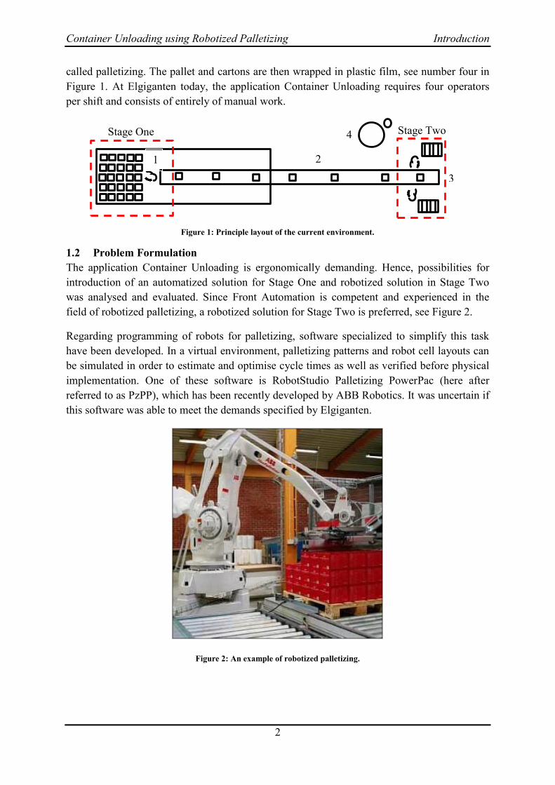
The application Container Unloading is ergonomically demanding. Hence, possibilities for
introduction of an automatized solution for Stage One and robotized solution in Stage Two
was analysed and evaluated. Since Front Automation is competent and experienced in the
field of robotized palletizing, a robotized solution for Stage Two is preferred, see Figure 2.
Regarding programming of robots for palletizing, software specialized to simplify this task
have been developed. In a virtual environment, palletizing patterns and robot cell layouts can
be simulated in order to estimate and optimise cycle times as well as verified before physical
implementation. One of these software is RobotStudio Palletizing PowerPac (here after
referred to as PzPP), which has been recently developed by ABB Robotics. It was uncertain if
this software was able to meet the demands specified by Elgiganten.
Figure 2: An example of robotized palletizing.
1 2
3
4 Stage One Stage Two

Container Unloading using Robotized Palletizing Introduction
3
Technology for gripping of cartons is another area that will be highlighted in this study. Due
to the broad variety of carton sizes, weights and orientations, the number of required gripping
devices and the design of these will be analysed.
At a first glance at a palletizing operation the complexity seems to be low, but there are many
factors to consider. The orientation of the cartons, the pick approach and the velocities are
some issues to manage. Another factor to consider is the visual appearance of the finished
pallets. In some cases the containers at Elgiganten hold more than one type of cartons, which
further increase the complexity. Currently, more than hundred different carton sizes are
present and approximately hundred new products are introduced every year. This means that
the solution must be flexible in order to handle the product variety. It is desirable for
operators, with neither technical education nor programming experience, to be able to
program new palletizing procedures within 20 minutes. Therefore, high demands on user-
friendliness are also required for the proposed solutions.
Purpose 1.3
Due to unsatisfactory work environment, the purpose is to evaluate potential solutions in
Stage One and define if robotized palletizing, using Palletizing PowerPac, is feasible and
applicable in Stage Two. The study will investigate the possibilities to improve the work
procedure of Container Unloading at Elgiganten with respect to cost-effective, ergonomic and
technical aspects.
Delimitations 1.4
The software PzPP was used for programming the robot. The reason for selecting this
software was based on two factors. Firstly, the software was recently released and therefore
no earlier studies exist. This makes software more interesting from an analytical point of
view. Secondly, earlier experiences and knowledge in RobotStudio, in which PzPP is
integrated, made the selection even more evident. The work procedure of Container
Unloading also consists of wrapping the pallets in plastic film and will not be considered in
this study.
Since it was complicated to estimate the gains of improved work environment in financial
terms, no financial analysis of the ergonomics have been made.
Due to the broad variety in weights, this study only focused on products weighing 30 kg or
less.
The following delimitations have been established:
Programming and evaluation will only be done on ABB’s PzPP and no other similar
software.
No investigation on how to wrap the pallets in plastic film will be made.
No financial analysis of the ergonomics has been made.
Products with weight more than 30 kg will not be included in the study
Specification of Question Formulation 1.5
The following questions are established in order to clarify the purpose of this study:
Container Unloading using Robotized Palletizing Introduction
4
Is it feasible for an operator with no experience in robot programming to setup a new
palletizing procedure in ABB’s software within 20 minutes?
Is it feasible to use robot palletizing for the whole range of products in the case
Elgiganten and if not which products are feasible?
How will the productivity be affected by the introduction of a robot solution?
How will the work environment be affected at Elgiganten?
What will the capacity level of the proposed solutions be?
Is it feasible and cost-effective to unload containers within two hours by using
robotized palletizing?
Report Disposition 1.6
The following chapter, Chapter 2, describes the methodology used in the project. In Chapter 3
the basic theory for the analysis is structured. The basic theory consists of e.g. general
information about robots, the software used, gripping technologies and ergonomic methods.
The situation analysis at the case of Elgiganten is highlighted in Chapter 4, which is the
analysis section. Also, the selection of grippers and cartons in focus are motivated in this
chapter. The report ends with a discussion and conclusion of the proposed solutions for
Elgiganten.

Container Unloading using Robotized Palletizing Methodology
5
2 Methodology
In this chapter a description of the way data were collected, the software PzPP was evaluated
and how the analysis was performed. The methodology is divided in four sections, Collection
of Data, Evaluation of Palletizing PowerPac, Verification at Front Automation and Analyses
of the Proposed Solutions.
Collection of Data 2.1
As a start, literature studies using Chalmers library and databases served as a base for the
collection of data for the theoretical framework. Study visits to and active dialogues with
relevant companies were kept in order to obtain expertise information and suggestions on
solutions for problems that occurred during the project. Visits to Elgiganten were also made
with the purpose of gathering data needed for ergonomic and productivity studies of the
manual work. The gathered data consisted of work postures and motions, cycle times and
operators’ view points on the work environment. The data constituted films, pictures and
unstructured interviews with the employees. The ergonomic studies were structured by two
methods, Rapid Entire Body Assessment (REBA) and The National Institute of Occupational
Safety and Health (NIOSH), and the human simulation software Jack. REBA is used for
analysing postures, while NIOSH is focusing on motions and are often used in this type of
operations. Jack was used for visualizing the ergonomic problem at Elgiganten and
highlighting specific parts of the body that are particularly burdened. Both methods and the
software were used because they complement each other. The ergonomic analyses were made
in three cases with varying pick approaches. Also guidelines provided by the Swedish work
environment authority, Arbetsmiljöverket, were used.
An Excel file containing data about e.g. carton dimensions and quantities was received from
Elgiganten, which served as a base in the selection of cartons in focus and gripper. From the
Excel file the number of arriving containers each month was established, which indicated a
suitable capacity level.
Evaluation of Palletizing PowerPac 2.2
The software PzPP is used for simulating robotized palletizing. Its possibilities and
deficiencies were studied by using various carton sizes and pallet patterns that are present at
Elgiganten. To verify the simulations, a physical robot station at Front Automation, see
section 2.3 was used to test accuracy, repeatability and robustness of the software. For
evaluation of user-friendliness, subjective impressions such as logical layout, appropriate
warnings and the time constraint of maximum 20 minutes was used. The usability was
analysed using simulation and rated upon for which product types robotized palletizing is
suitable in both cost-effective and productivity aspects.
Verification at Front Automation 2.3
To verify simulations made in PzPP, investigate robot performance and appropriate robot
motion values as well as suitable gripper design, a robot station at Front Automation was
Container Unloading using Robotized Palletizing Methodology
6
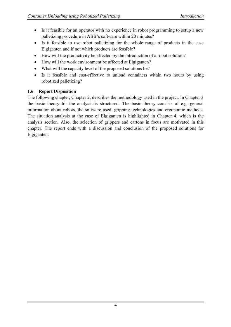
used. The layout of the station consisted of two conveyors, a robot and a gripping tool, see
Figure 3.
Figure 3: Layout of robot station at Front Automation.
The conveyors constituted in- and out feeders which were arranged perpendicular to each
other and have a height of 40 cm. The robot is model IRB460 by ABB and was positioned on
a stand with a height of 80 cm. For further specifications regarding the robot, see [3].
As gripping tool, a vacuum pad called UniGripper was used. The tool, see Figure 4, had a
suction area of 200x300 mm with foam thickness 10 mm and circular suction activators with
radii five mm distributed over the pad. The tool was equipped with an optional function called
“floating plate”, which allowed compensation for variations in carton heights. During
verifications, tests were made both with and without the floating plate function.
The verifications were carried out by repeatedly gripping a carton at the in feeder and move it
to the out feeder, which created the pallet pattern seen in Figure 3. The cartons had
dimensions 400x600x250 mm (width, length and height) with weights ranging from nine kg
to fifteen kg.

Container Unloading using Robotized Palletizing Methodology
7
Figure 4: Gripping tool called UniGripper to the left and vacuum pad design to the right.
Analyses of Proposed Solutions 2.4
To analyse the proposed solutions different approaches and methods have been used. The
dimensions analysed were productivity, cost-effectiveness and ergonomics. For all solutions,
two states were compared and analysed. The Current State refers to the current situation at
Elgiganten today, where no automation is present. The Future State refers to when an
improvement of the manual work in Stage One and robotized palletizing in Stage Two of the
application Container Unloading are implemented. Since no physical implementation was
made at Elgiganten in Future State, all analyses were done through simulation in PzPP and
verifications at Front Automation’s robot station.
When analysing productivity, changes in output of products and application cycle time
between the two states was measured. This yielded a ratio between the states and thus
productivity was given.
When the work environment was analysed with regards to ergonomics, REBA and NIOSH
lifting equation were used in each state. Note that the ergonomic analysis was only carried out
for Stage One because the results for Stage Two will be almost the same. From an ergonomic
viewpoint the work procedure is the same in Stage Two even if the procedure is performed in
reverse order compared to Stage One.
To systematically evaluate the proposed solutions, two evaluation methods, Pugh matrix and
Kesselring matrix was used. The Pugh matrix is a decision-matrix for comparing possible
solutions based on given criteria to a reference solution. Solutions considered better than the
reference solution are further analysed in a Kesselring matrix, where the criteria are assigned
weights.
Regarding analysing the robustness of the solution, this has been made both in the software
PzPP and in the physical robot station at Front Automation. The purpose of this analysis was
to investigate how robust the solution is concerning disturbance factors, such as operator
errors and error detection by the software. The analysis also covers evaluation of PzPP, its
robustness and reliability.

Container Unloading using Robotized Palletizing Theoretical Framework
8
3 Theoretical Framework
In this chapter, Industry Characteristics basic knowledge of Industrial Robots and Robot
Programming is highlighted. Also, Gripping Technologies and Identification Systems are
presented. Last the Ergonomic and Systematic Evaluation methods that are used in this study
and Existing Solutions are described.
Industry Characteristics 3.1
To further understand the problem a description of characteristics in the industry is presented.
This section begins with general information about transportation of objects by containers and
follows by a description of what to consider when palletizing. Finally, a presentation of
Elgiganten and their business is made.
3.1.1 Container Transportation
Since globalisation increases, the transportations of finished goods are increasing as well.
Many of the fastest growing economies in production are located in Southeast Asia, but the
consumption per capita is still highest in the Western world [4] [5]. The most cost-effective
transportation alternative for this far distance is by ship see Figure 5 [6].
Figure 5: Transportation costs per unit over distances.
When the distances are shorter it is more cost-effective and flexible to transport by truck or by
train. The figure covers the three most common transportation systems, where C1 is the cost
for transporting one unit by truck, C2 is the cost for transporting one unit by train and C3
refers to cost for shipping transportation of one unit. The distance D1 is normally located
between 500 and 750 km from departure while D2 is near 1500 km. Noteworthy, this figure is
simplicity of the reality and for a further analysis of transportation situation in a particular
case a more exactly calculated version is needed.
Container Unloading using Robotized Palletizing Theoretical Framework
9
In year 2009 the transportation by ship amounts to over 27 million TEUs [7], where one TEU
is equal to one 20 foot container. In transportation of goods by ship the most common way is
to use containers. A main advantage of using ships instead of trains is transportation volume,
which are significantly higher for ships. Products not dependent on time are also beneficial to
transport by ship. There are mainly three different types of standard containers, 20 foot, 40
foot and 40 foot High Cube [8].
3.1.2 Pallets and Palletizing
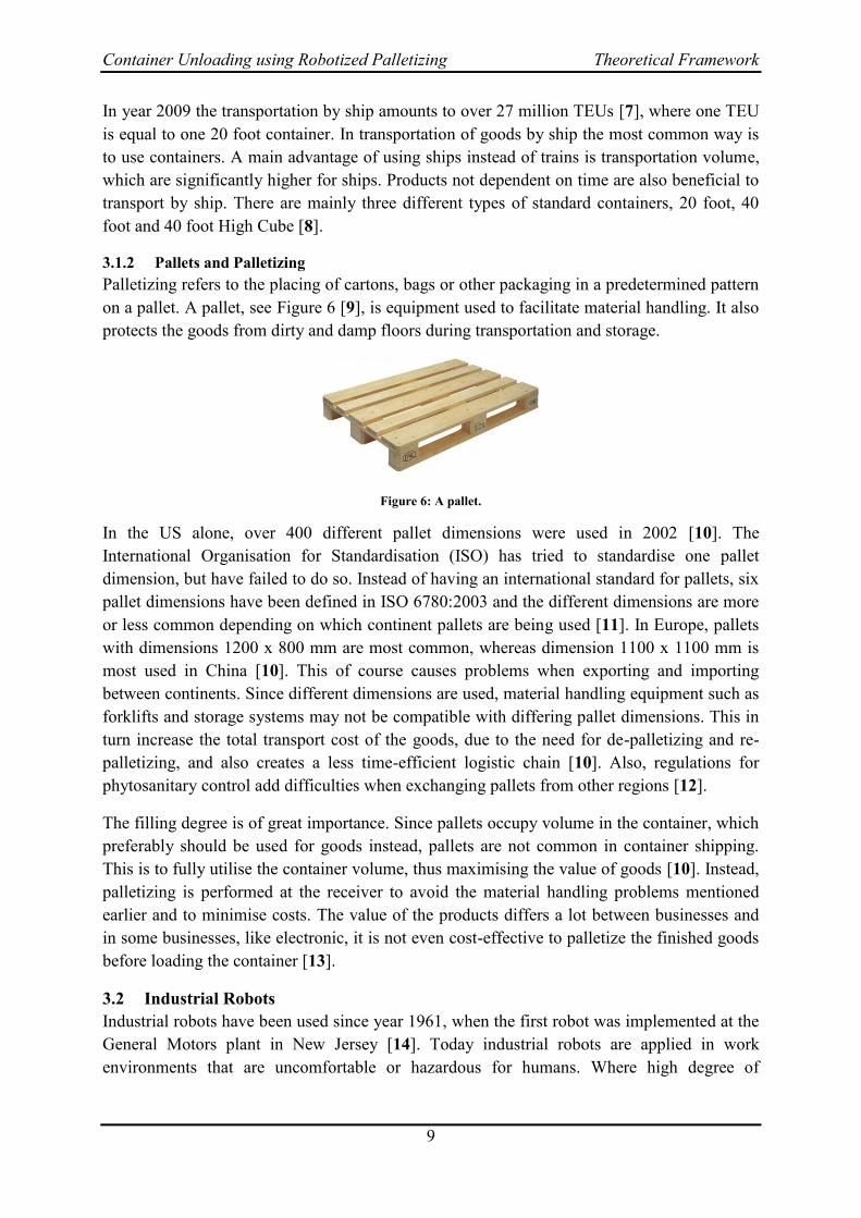
Palletizing refers to the placing of cartons, bags or other packaging in a predetermined pattern
on a pallet. A pallet, see Figure 6 [9], is equipment used to facilitate material handling. It also
protects the goods from dirty and damp floors during transportation and storage.
Figure 6: A pallet.
In the US alone, over 400 different pallet dimensions were used in 2002 [10]. The
International Organisation for Standardisation (ISO) has tried to standardise one pallet
dimension, but have failed to do so. Instead of having an international standard for pallets, six
pallet dimensions have been defined in ISO 6780:2003 and the different dimensions are more
or less common depending on which continent pallets are being used [11]. In Europe, pallets
with dimensions 1200 x 800 mm are most common, whereas dimension 1100 x 1100 mm is
most used in China [10]. This of course causes problems when exporting and importing
between continents. Since different dimensions are used, material handling equipment such as
forklifts and storage systems may not be compatible with differing pallet dimensions. This in
turn increase the total transport cost of the goods, due to the need for de-palletizing and re-
palletizing, and also creates a less time-efficient logistic chain [10]. Also, regulations for
phytosanitary control add difficulties when exchanging pallets from other regions [12].
The filling degree is of great importance. Since pallets occupy volume in the container, which
preferably should be used for goods instead, pallets are not common in container shipping.
This is to fully utilise the container volume, thus maximising the value of goods [10]. Instead,
palletizing is performed at the receiver to avoid the material handling problems mentioned
earlier and to minimise costs. The value of the products differs a lot between businesses and
in some businesses, like electronic, it is not even cost-effective to palletize the finished goods
before loading the container [13].
Industrial Robots 3.2
Industrial robots have been used since year 1961, when the first robot was implemented at the
General Motors plant in New Jersey [14]. Today industrial robots are applied in work
environments that are uncomfortable or hazardous for humans. Where high degree of

Container Unloading using Robotized Palletizing Theoretical Framework
10
accuracy and repeatability is required, e.g. in arc welding, robots are also favourable to
implement.
The difference between accuracy and repeatability is illustrated in Figure 7 [15]. The
definition of repeatability is the ability of the robot to reach a certain position over and over
again. Accuracy of the robot specifies how closely it can reach this position.
Figure 7: Illustration of accuracy and repeatability.
Robots are constructed of joints and links, which can easily be compared to the human body.
Each link is connected with another link by a joint. Each joint, or axis, provides the robot with
the degrees-of-freedom of motion and the number of degrees-of-freedom often classifies the
robots. Joint types can exist in form of both translational and rotational characteristic. Almost
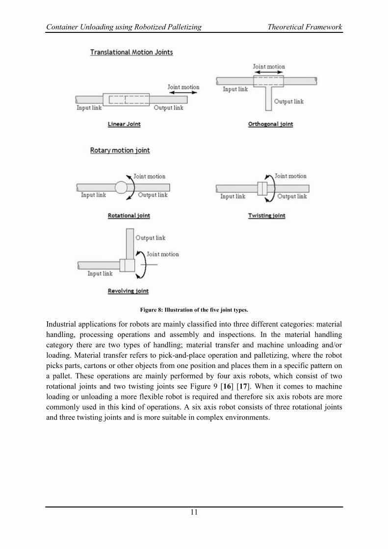
all industrial robots are made up using one or more of these five joint types, see Figure 8:
Linear – The axes of the input link and output link are parallel. It is translational
sliding motion.
Orthogonal – This joint type is the same as the linear joint type, but the output link is
perpendicular to the input link during the movement.
Rotational – In this rotational motion, the rotation is around an axis which is
perpendicular to the axes of the input and output links.
Twisting – Same as the rotational joint type but the rotary motion is around an axis
which is parallel to the axes of the links.
Revolving – The joint motion of this joint type is the same as the twisting joint type
but the output link is perpendicular to the input link during the move.
Container Unloading using Robotized Palletizing Theoretical Framework
11
Figure 8: Illustration of the five joint types.
Industrial applications for robots are mainly classified into three different categories: material
handling, processing operations and assembly and inspections. In the material handling
category there are two types of handling; material transfer and machine unloading and/or
loading. Material transfer refers to pick-and-place operation and palletizing, where the robot
picks parts, cartons or other objects from one position and places them in a specific pattern on
a pallet. These operations are mainly performed by four axis robots, which consist of two
rotational joints and two twisting joints see Figure 9 [16] [17]. When it comes to machine
loading or unloading a more flexible robot is required and therefore six axis robots are more
commonly used in this kind of operations. A six axis robot consists of three rotational joints
and three twisting joints and is more suitable in complex environments.

Container Unloading using Robotized Palletizing Theoretical Framework
12
Figure 9: A six axis robot to the left and a four axis robot to the right.
In process operations like spot welding, arc welding, spray coating, robots are preferably
implemented because of the level of quality and the repeatability a robot can achieve. In this
kind of operations the possibility to adjust the angle of the tool is important and therefore 6
axis robots are mainly used.
Assembly and inspection is a combination of the two previous categories. In more simple and
frequent operations it is cost-effective to implement a robot instead of having employees
perform these operations with risk of getting ergonomic injuries. In operations where high
degree of flexibility is required humans are still the most preferred solution [14].
3.2.1 Robot Programming
Each robot needs a program to follow when performing the motions for the operation. The
program is established either by online or offline programming or a combination of them. In
online programming the program is established by moving the robot to the desired positions,
called jogging. This jogging operation is performed by a handheld device called
TeachPendant [14]. In this device it is also possible to, for example change digital inputs and
digital outputs manually, adjust in the program and get instructions when problems occur. In
online programming you are basically teaching the robot a sequence by moving the robot to
different positions in the sequence.
In offline programming, on the other hand, computer software is used for establishing the
program for the robot. One benefit of offline programming compared with online
programming is downtime in production while new program is constructing. The program is
made in the computer software and the production is just stopped during implementation of
the new program or verification of positions between the virtual model and the reality.
Another benefit with offline programming is the ability to test the program before
implementation.

Container Unloading using Robotized Palletizing Theoretical Framework
13
3.2.2 Palletizing PowerPac
This section will describe the way of working with ABB RobotStudio’s add-in PzPP in order
to create pallets with products as specified by the user. The purpose with the software is to
create and simulate palletizing processes in an easy, quick and flexible way without the need
of any robot programming skills. Rather than programming pick-and-place sequences,
conveyors and gripping tools, the system is configured in a window based environment.
Compared to traditional methods this will radically reduce programming time [18].
PzPP is a further development of ABB’s palletizing software PickMaster5 with the aim to
simplify the simulation of palletizing processes even more. The main difference between the
software, see Figure 10 is that PzPP offers a visualised simulation environment for the whole
palletizing process, whereas in PickMaster5 this is not available [19] [20]. Also, PzPP is
integrated in RobotStudio instead of being a stand-alone application [21] [19].
Figure 10: PickMaster5 to the left and its successor PzPP to the right.
Before any work with PzPP can take place, the virtual controller for the robot system in
RobotStudio must be prepared in order for all necessary signals used to be included. This is
done when a new robot system is created and is called the “Prepare for PickMaster”-option.
ABB has included most of their four- and six axis robots to choose from. Once a robot has
been chosen and the system is created, the PzPP is ready for use.
The PzPP menu tab in RobotStudio is seen in Figure 11. It contains ten different categories
with different build components, where the following five categories are necessary in the
workflow of creating a simulated palletizing process:
Build Cell Product Data Programming Validate Simulation
Figure 11: The PzPP menu tab in RobotStudio.
In the “Build Cell” category, tools and product feeders are imported and added to the robot
and robot cell respectively. ABB has included five standard tools as SmartComponents to

Container Unloading using Robotized Palletizing Theoretical Framework
14
choose from. These tools contain functions such as vacuum picking for cartons, claw gripping
for bags and pallet searching. Since there are standard tools, editing of tool signals is not
needed [21]. For transportation of products and pallets in and out of the robot cell, conveyor
tracks called feeders are used. Three types of feeders are commonly used; in-, out- and pallet
feeder.
Dimensions and weights of products and pallets are defined in the “Product Data” category,
see Figure 12. When products and pallets are defined, pallet patterns based on data in the
previous step are automatically generated. The generated patterns are then added to the pallet
layer by layer, see Figure 13.
Figure 12: Definition of dimensions and weight of a carton.

Container Unloading using Robotized Palletizing Theoretical Framework
15
Figure 13: Selection of automatically generated pallet patterns
The next category, “Programming”, handles how the tool should pick products and how the
palletizing job is to be performed. In Pick Setting, the orientation and displacement of the
tool, see Figure 14, with respect to the product is specified.
Figure 14: Orientation and displacement of tool.
To create the palletizing process, a job is added using the “Add Job”-button, where feeders for
feeding the robot with products are assigned and which feeder to use for placing the pallet
pattern is defined.
The last category before simulation, “Validate”, is used to ensure that the robot is able to
reach all pick and place targets. This is done by using the “Check Reach”-button. Optionally,
the palletizing process can be previewed before actual simulation takes part.

Container Unloading using Robotized Palletizing Theoretical Framework
16
In “Simulation” the palletizing process is downloaded to the virtual controller in RobotStudio
and simulated, see Figure 15, before any implementations to the physical robot controller are
made.
Figure 15: Snapshot of the simulated palletizing process.
After all steps have been completed and the simulation generated a satisfactory result, the
palletizing project is complete and can be applied in the real robot cell.
Gripping Technologies 3.3
This section will describe what the definition of a gripper is, give examples of different types
of gripping technologies used in automated systems and define the requirements put on a
gripper. A deeper explanation of vacuum grippers and how to achieve vacuum will also be
provided.
3.3.1 Classification of Grippers
Grippers are defined in one way as [22]:
“Grippers are subsystems of handling mechanisms which provide temporary
contact with the object to be grasped. They ensure the position and orientation
when carrying and mating the object of the handling equipment”
There are different ways for gripping an object. Figure 16 shows gripping of a spherical
object using six variants of grippers [22].

Container Unloading using Robotized Palletizing Theoretical Framework
17
Figure 16: Six different ways of gripping a spherical object.
The classification of grippers can be made into four different categories as per below:
Impactive mechanical grippers
Ingressive grippers
Contigutive prehension
Astrictive grippers
Impactive mechanical grippers, for example gripper two and three in Figure 16, use
mechanical force to grip the object. These grippers are the most frequently used types and
consists normally of two or four fingers depending on the object to be gripped. In order to
manipulate the fingers, different drive systems are used. Drive systems are of mechanical,
pneumatic, hydraulic or magnetic types. The choice of appropriate system depends on criteria
and rankings of these, such as gripping force, costs, maintenance and controllability. Typical
object materials for impactive mechanical grippers are rigid objects.
Ingressive grippers are used for objects that made of non-solid materials, such as textiles. By
using serrated edges, gripping in a pinch-like manner is achieved. In contrast to impactive
grippers, ingression is applied on one surface and the object can be held without the need to
continuously apply force.
Contigutive prehension includes grippers that use either chemo- or thermo adhesion, see
gripper six in Figure 16. For chemo adhesion, tapes which are spun upon spools or
permanently tacky pads are utilized to attach the object to the gripper. This requires changing
the tape or cleaning the pads after a number of cycles in order to obtain the same retention
force. Thermo adhesion uses small droplets of water in combination with liquid carbon
dioxide. As the water freezes, an adhesive layer is formed between the object and the gripper.
Astrictive grippers have the ability to provide retention force without the need of any
compressive stresses. Vacuum suction, electro- and magnet adhesion, see gripper four and
five in Figure 16, are examples of this type of gripping technology. Grippers of this type

Container Unloading using Robotized Palletizing Theoretical Framework
18
require, a continuous stream of energy, i.e. air or electricity, to preserve the retention between
object and gripper [22].
3.3.2 Requirements on a Gripper
When selecting a gripper, four characteristics and requirements come into play [22]:
Technological requirements
Effects of gripped objects
Handling equipment
Environmental parameters
Prehension time, gripping path and number of objects gripped per cycle is defined as
technological requirements. Effects on gripped objects include mass, type of material,
temperature and tolerances of the object. One example is that grippers using magneto
adhesion are limited to magnetically susceptible objects, such as iron and steel. There are
correlations between gripper and object, such as object mass and gripping force needed,
object position and gripping, that need to be taken into consideration. Factors regarding
handling equipment are what type of connections, mechanical, electrical or fluidic, are desired
as well as the positional accuracy of the object required by the application. The environmental
parameters include ambient temperature and humidity, vibrations and possible
contaminations.
3.3.3 Vacuum Gripping
In automated processes with short cycles times where the object is relatively rigid and has a
non-porous surface, vacuum gripping is suitable [23]. Depending on the design of the vacuum
gripping tool, plastic bags and objects with curved surfaces is also subject to this type of
gripping [22]. There are different types of gripping approaches where either suction cups or
vacuum pads as depicted in Figure 17 are used [24]. A vacuum pad comprises of mainly three
parts, but the design of parts and additional features vary depending on manufacturer [24]
[25]. The top part in Figure 17 is the housing for the vacuum generator and a manometer for
measuring of the obtained vacuum. The middle part is a valve module which contains vacuum
regulation valves. A foam sealing mat is used at the bottom for secure gripping of objects and
to reduce sliding.

Container Unloading using Robotized Palletizing Theoretical Framework
19
Figure 17: Exploded view of a vacuum pad.
3.3.4 Vacuum Theory
At sea level, the atmospheric pressure is 101,325 kPa or 1013 mBar. As the altitude increases,
the atmospheric pressure decreases. For vacuum to occur, a difference in atmospheric
pressure and applied vacuum pressure must exist. The prehension force Fp on an object has a
proportional linear relationship to these pressures and the prehension surface area A as, Eq.
5.3 [22]:
( ) [1]
where,
= atmospheric pressure [bar]
= applied vacuum pressure [bar]
A = effective interface area between suction cup and object surface [m2]
For astrictive grippers using vacuum suction, the vacuum is created by a vacuum generator
which clears the air between the pad and the object. Since the pad and the object are in
contact, no air can enter and vacuum is created.
When prehension is achieved, additional factors have to be considered. The following
equation gives the effective suction force Fs with respect to these factors, Eq. 5.4 [22]:
( )
[2]
where,
n = deformation coefficient for suction cups
= system efficiency considering leakage losses
z = number of suction cups [pcs]
s = safety factor
m = mass of object [kg]
g = force of gravity [m/s2]
further parameters are described in equation [1].
Container Unloading using Robotized Palletizing Theoretical Framework
20
s is given as [26]:
1: For very controlled conditions with very little risk for injury and/or machine failure.
1.5 Default value.
3-5 High or very high risk for personal injury and/or machine failure
Identification Systems 3.4
Several approaches and possibilities to robot vision systems are available. This section will
first present the steps performed in a general machine vision system and then two different
technologies used.
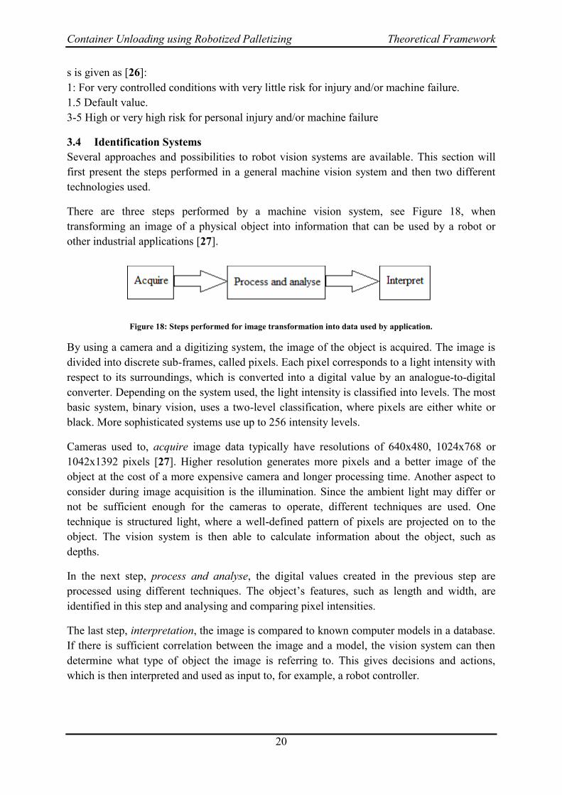
There are three steps performed by a machine vision system, see Figure 18, when
transforming an image of a physical object into information that can be used by a robot or
other industrial applications [27].
Figure 18: Steps performed for image transformation into data used by application.
By using a camera and a digitizing system, the image of the object is acquired. The image is
divided into discrete sub-frames, called pixels. Each pixel corresponds to a light intensity with
respect to its surroundings, which is converted into a digital value by an analogue-to-digital
converter. Depending on the system used, the light intensity is classified into levels. The most
basic system, binary vision, uses a two-level classification, where pixels are either white or
black. More sophisticated systems use up to 256 intensity levels.
Cameras used to, acquire image data typically have resolutions of 640x480, 1024x768 or
1042x1392 pixels [27]. Higher resolution generates more pixels and a better image of the
object at the cost of a more expensive camera and longer processing time. Another aspect to
consider during image acquisition is the illumination. Since the ambient light may differ or
not be sufficient enough for the cameras to operate, different techniques are used. One
technique is structured light, where a well-defined pattern of pixels are projected on to the
object. The vision system is then able to calculate information about the object, such as
depths.
In the next step, process and analyse, the digital values created in the previous step are
processed using different techniques. The object’s features, such as length and width, are
identified in this step and analysing and comparing pixel intensities.
The last step, interpretation, the image is compared to known computer models in a database.
If there is sufficient correlation between the image and a model, the vision system can then
determine what type of object the image is referring to. This gives decisions and actions,
which is then interpreted and used as input to, for example, a robot controller.
Container Unloading using Robotized Palletizing Theoretical Framework
21
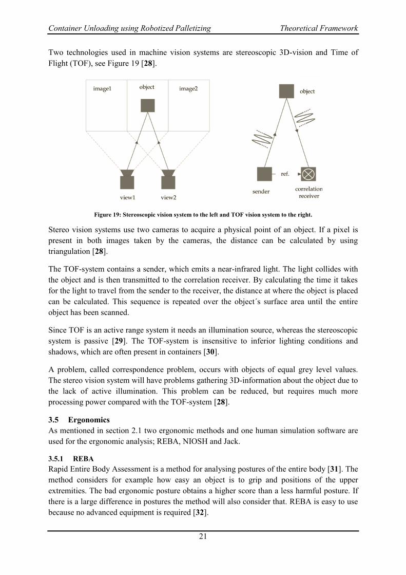
Two technologies used in machine vision systems are stereoscopic 3D-vision and Time of
Flight (TOF), see Figure 19 [28].
Figure 19: Stereoscopic vision system to the left and TOF vision system to the right.
Stereo vision systems use two cameras to acquire a physical point of an object. If a pixel is
present in both images taken by the cameras, the distance can be calculated by using
triangulation [28].
The TOF-system contains a sender, which emits a near-infrared light. The light collides with
the object and is then transmitted to the correlation receiver. By calculating the time it takes
for the light to travel from the sender to the receiver, the distance at where the object is placed
can be calculated. This sequence is repeated over the object´s surface area until the entire
object has been scanned.
Since TOF is an active range system it needs an illumination source, whereas the stereoscopic
system is passive [29]. The TOF-system is insensitive to inferior lighting conditions and
shadows, which are often present in containers [30].
A problem, called correspondence problem, occurs with objects of equal grey level values.
The stereo vision system will have problems gathering 3D-information about the object due to
the lack of active illumination. This problem can be reduced, but requires much more
processing power compared with the TOF-system [28].
Ergonomics 3.5
As mentioned in section 2.1 two ergonomic methods and one human simulation software are
used for the ergonomic analysis; REBA, NIOSH and Jack.
3.5.1 REBA
Rapid Entire Body Assessment is a method for analysing postures of the entire body [31]. The
method considers for example how easy an object is to grip and positions of the upper
extremities. The bad ergonomic posture obtains a higher score than a less harmful posture. If
there is a large difference in postures the method will also consider that. REBA is easy to use
because no advanced equipment is required [32].
Container Unloading using Robotized Palletizing Theoretical Framework
22
REBA consists mainly of four steps:
1. Select a sample principle
2. Collect body postures
3. Analyse the postures
4. Compile the result
The sample can be selected by identification of bad work postures, analysis of time sampling
or through task analysis. In identification of bad work postures the whole work cycle is
observed and some hazardous work postures are selected. Analysis of time sampling refers to
the posture a worker/operator has at a specific time for example every tenth second during a
period of ten to twenty minutes. For the task analysis the work cycle is divided different
operations were each operation’s posture can be analysed.
In collection of the body postures a video camera is commonly used but just photos works
well when identifying work postures.
When analysing the postures and compiling the results it is important to explain and motivate
why a posture causes a certain score. This will facilitate the improvement work of the
operations.
3.5.2 NIOSH
The Revised NOISH Lifting equation is a method for analysing motions during lifting [31]
[33]. Experts from The National Institute of Occupational Safety and Health in USA have
developed an equation, which considers factors related to workload tolerances in order to
identify limiting values of the maximal load that should be handled. Two common limiting
values are: Action Limit (AL, which is recommended lifting limit) and Maximum Permissible
Limit (MPL, which is maximum lifting limit). Values lower than AL can be performed by 99
% of all men and 75 % of all women without risk of injury. Work situations, which give
values higher than MPL-level, indicates that there are high risks of getting hurt and these
situations must be improved immediately.
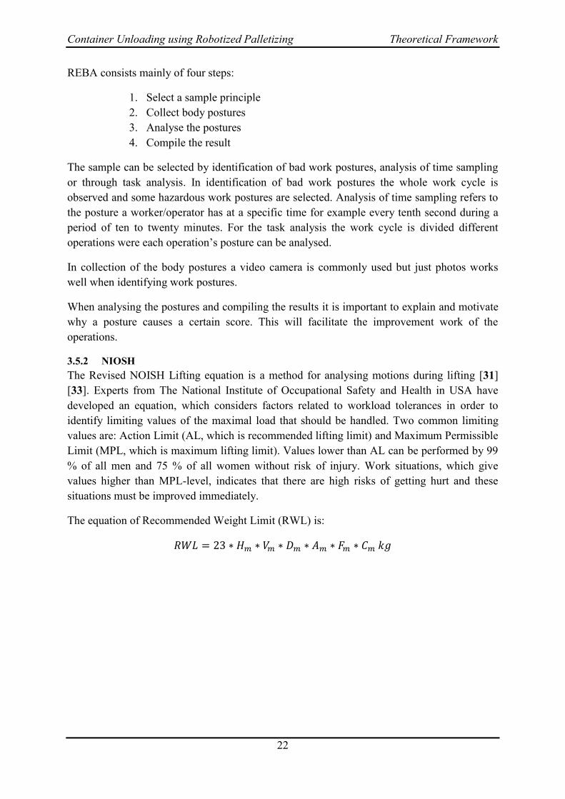
The equation of Recommended Weight Limit (RWL) is:
Container Unloading using Robotized Palletizing Theoretical Framework
23
Figure 20: Definition of the lifting variables H, V, D, A, F and C.
where,
= a horizontal factor = 25/H, where H is the horizontal distance from the
operators’ feet to the gripping position of the object.
= a vertical factor = 1-0,003│V-75│, where V is the vertical distance from
the operators’ feet to the gripping position of the object.
= a distance factor = 0,82 + 4,5/D, where D is the lifting distance.
= an asymmetric constant = 1-0,0032A, where A is the asymmetric angle
relative upper body when lifting.
= a frequency factor and has a value between zero and one. This value could
be found in Table 6 in Appendix – Ergonomics.
= a coupling factor, which has a value between zero and one and is also
received from Table 7 in Appendix – Ergonomics.
3.5.3 JACK
The Centre of Human Modelling and Simulation at the University of Pennsylvania began to
develop Jack in mid-1980s. During the beginning of the development they had significant
support by the US Army and NASA, but today it is marketed and developed by multinational
conglomerated company, Siemens.
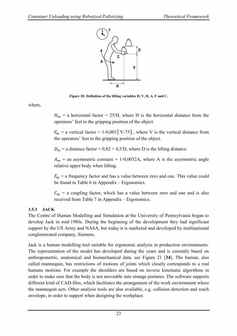
Jack is a human modelling tool suitable for ergonomic analysis in production environments.
The representation of the model has developed during the years and is currently based on
anthropometric, anatomical and biomechanical data, see Figure 21 [34]. The human, also
called mannequin, has restrictions of motions of joints which closely corresponds to a real
humans motions. For example the shoulders are based on inverse kinematic algorithms in
order to make sure that the body is not moveable into strange postures. The software supports
different kind of CAD-files, which facilitates the arrangement of the work environment where
the mannequin acts. Other analysis tools are also available, e.g. collision detection and reach
envelope, in order to support when designing the workplace.
Container Unloading using Robotized Palletizing Theoretical Framework
24
Figure 21: A human representation in Jack from 1980s to the left and current representation to the right.
The software enables creation of animations in a Task Simulation Builder. In the builder it is
possible to put together different tasks, e.g. put, go and reach, into a sequence. From this
sequence it is possible to acquire an ergonomic report consisting of joint angles, joint torques
and percentage of the population who is capable of executing the sequence without risk of
injury.
Systematic Evaluation 3.6
For selecting the most appropriate and applicable solution for Elgiganten two systematic
evaluation methods, Pugh matrix and Kesselring matrix, has been used. In the Pugh matrix the
different solutions is compared to a reference, which often constitute of the existing solution.
This comparison is based on the predetermined criteria. Solutions better or worse than the
reference in the specific criteria get a plus respective minus. If it is impossible to separate the
solution and the reference a zero is marked. The solution/-s with the highest net value is
passed to the further development process.
The second method used, Kesselring matrix, uses the same criteria but in this matrix the
criteria is weighted. The weighting varies between one and five and if a criterion is important
the assigned value is five. The total score from the solutions are compared to an ideal
solution.
Existing Solutions 3.7
In this section several existing solutions for the application Container Unloading is presented.
The four following solutions refer to Stage One, which is unloading the cartons from the
container to the conveyor belt. Stage One is further described in section 1.1. After these four
solutions, two solutions for both Stage One and Stage Two are presented. This section is
ended with a description of the Container Unloading procedure at Attends and IKEA.
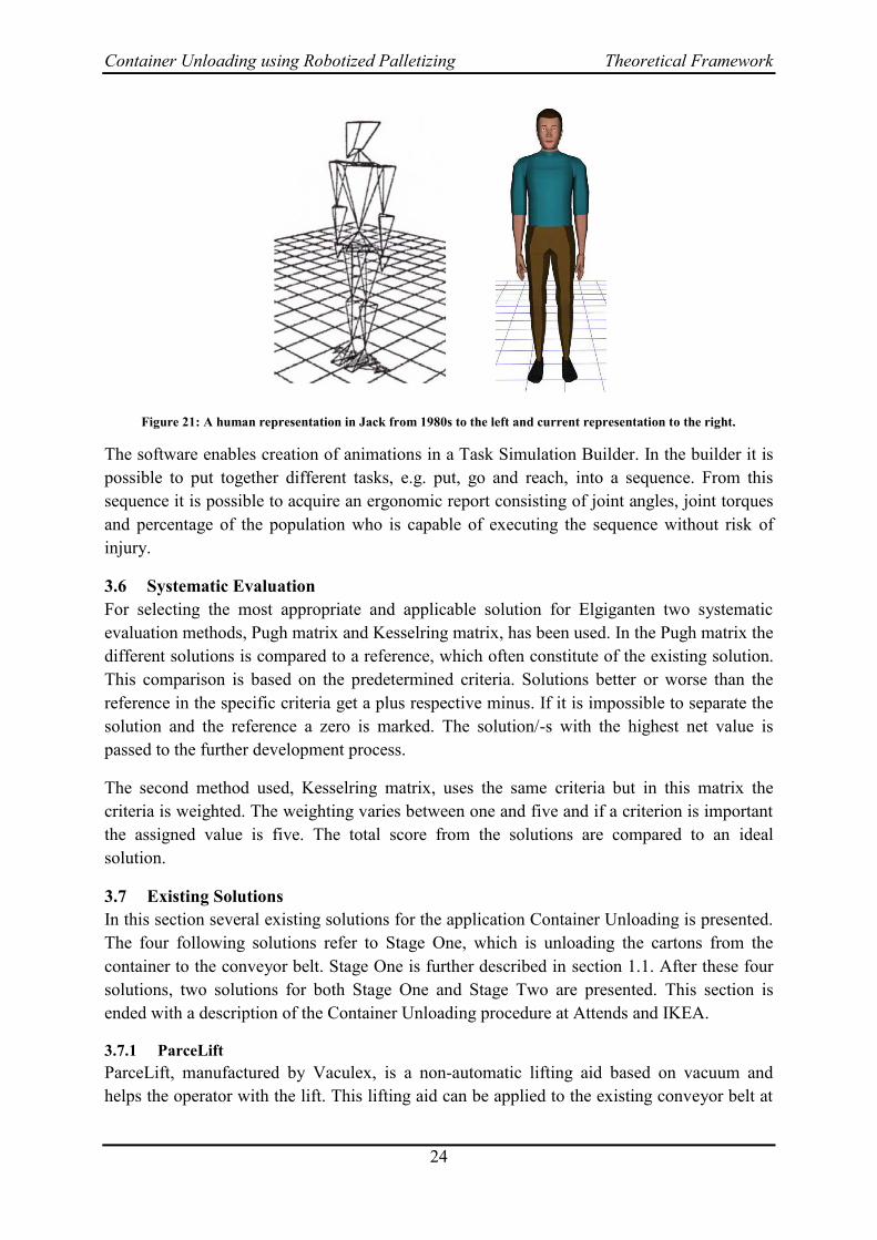
3.7.1 ParceLift
ParceLift, manufactured by Vaculex, is a non-automatic lifting aid based on vacuum and
helps the operator with the lift. This lifting aid can be applied to the existing conveyor belt at
Container Unloading using Robotized Palletizing Theoretical Framework
25
Elgiganten, see Figure 22. ParceLift is specially developed for loading and unloading
containers [35]. From an ergonomic point of view this helping device is better than manual
work [36]. The tool can be attached to the cartons from all sides, which increase the flexibility
of it.
Figure 22: The ParceLift.
ParceLift has a recommended max load of 40 kg and the unloading capacity is limited by the
operator. It is suitable for both 20 foot and 40 foot containers because it is applied to the
conveyor belt. The investment cost, which includes full installation, is 250 000 SEK [37].
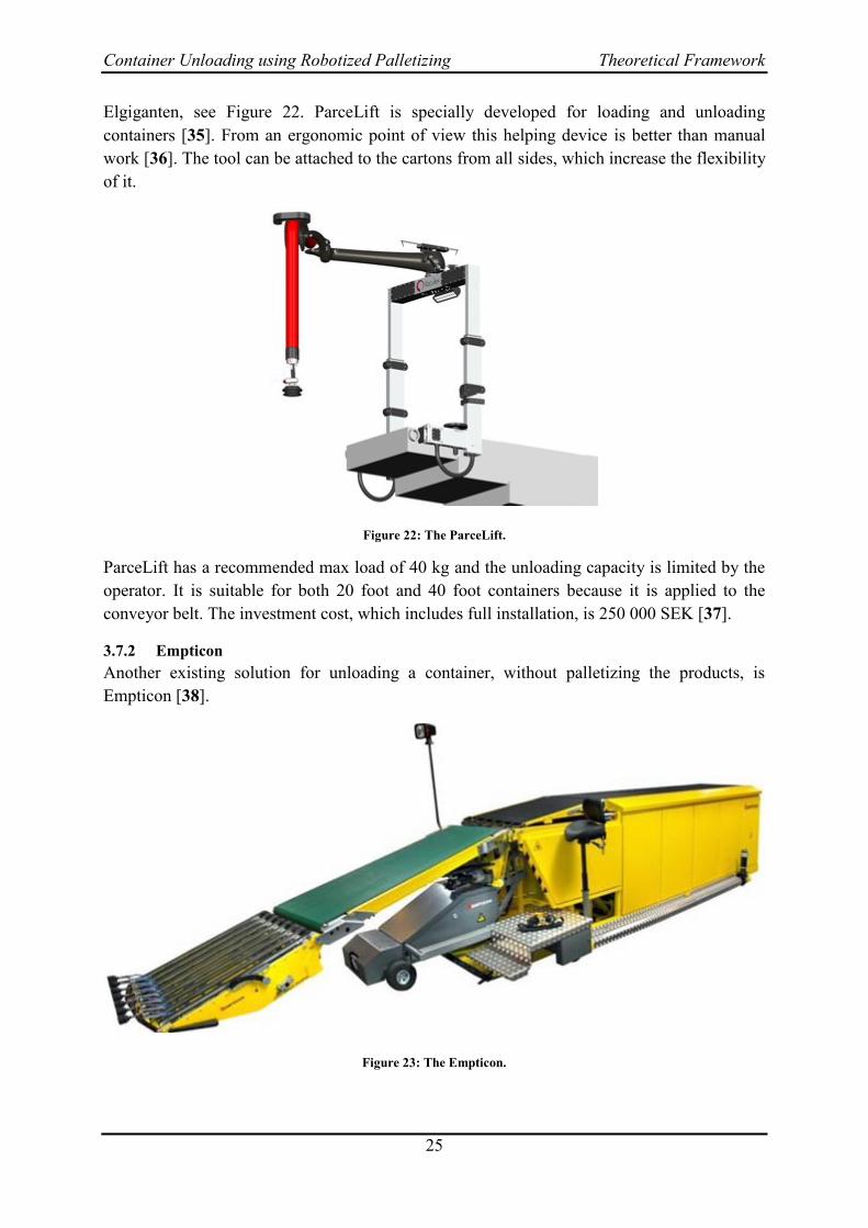
3.7.2 Empticon
Another existing solution for unloading a container, without palletizing the products, is
Empticon [38].
Figure 23: The Empticon.
Container Unloading using Robotized Palletizing Theoretical Framework
26
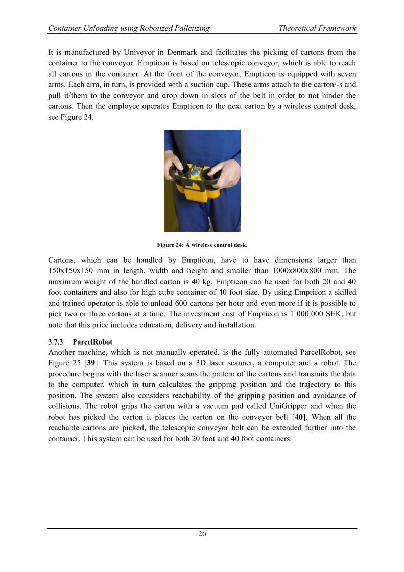
It is manufactured by Univeyor in Denmark and facilitates the picking of cartons from the
container to the conveyor. Empticon is based on telescopic conveyor, which is able to reach
all cartons in the container. At the front of the conveyor, Empticon is equipped with seven
arms. Each arm, in turn, is provided with a suction cup. These arms attach to the carton/-s and
pull it/them to the conveyor and drop down in slots of the belt in order to not hinder the
cartons. Then the employee operates Empticon to the next carton by a wireless control desk,
see Figure 24.
Figure 24: A wireless control desk.
Cartons, which can be handled by Empticon, have to have dimensions larger than
150x150x150 mm in length, width and height and smaller than 1000x800x800 mm. The
maximum weight of the handled carton is 40 kg. Empticon can be used for both 20 and 40
foot containers and also for high cube container of 40 foot size. By using Empticon a skilled
and trained operator is able to unload 600 cartons per hour and even more if it is possible to
pick two or three cartons at a time. The investment cost of Empticon is 1 000 000 SEK, but
note that this price includes education, delivery and installation.
3.7.3 ParcelRobot
Another machine, which is not manually operated, is the fully automated ParcelRobot, see
Figure 25 [39]. This system is based on a 3D laser scanner, a computer and a robot. The
procedure begins with the laser scanner scans the pattern of the cartons and transmits the data
to the computer, which in turn calculates the gripping position and the trajectory to this
position. The system also considers reachability of the gripping position and avoidance of
collisions. The robot grips the carton with a vacuum pad called UniGripper and when the
robot has picked the carton it places the carton on the conveyor belt [40]. When all the
reachable cartons are picked, the telescopic conveyor belt can be extended further into the
container. This system can be used for both 20 foot and 40 foot containers.

Container Unloading using Robotized Palletizing Theoretical Framework
27
Figure 25: The ParcelRobot.
The ParcelRobot enables unloading of up to 500 cartons per hour and cartons up to 60 kg can
be handled. Dimensions of the cartons can differ between 200 to 600 mm for each edge length
[41]. The investment cost of this system is 2 500 000 SEK.
3.7.4 Random Box Mover
The company Universal Robotics has developed an application called “Random Box Mover”
(RBM) for detection, identification and moving of cartons distributed in a random pattern.
RBM uses structured light and low-cost cameras for stereoscopic 3D-vision, see Figure 26.
Figure 26: Principal layout of Random Box Mover.
The image processing is managed by the company’s own software, Spatial Vision Robotics,
which generates the position of the carton by using the coordinates (X, Y and Z) together with
Container Unloading using Robotized Palletizing Theoretical Framework
28
the rotation of the carton in a given coordinate frame. This serves as an input to the PC-based
software where the information is converted to suite chosen robot controller and as a result,
the robot knows where the carton is located.
The system is universal in the sense that it works with several different robot brands and
models. Combined with a Motoman MH50-20 robot using the DX100 controller, RBM has
the capacity to move 720 cartons per hour that are positioned in any orientation. The
application manages cartons with dimensions varying from 152 x 152 x 3 mm to cubic cartons
with side lengths of 1219 mm. The accuracy can be varied between ± 0.5 mm to ± 5 mm
depending on the requirements of precision [42].
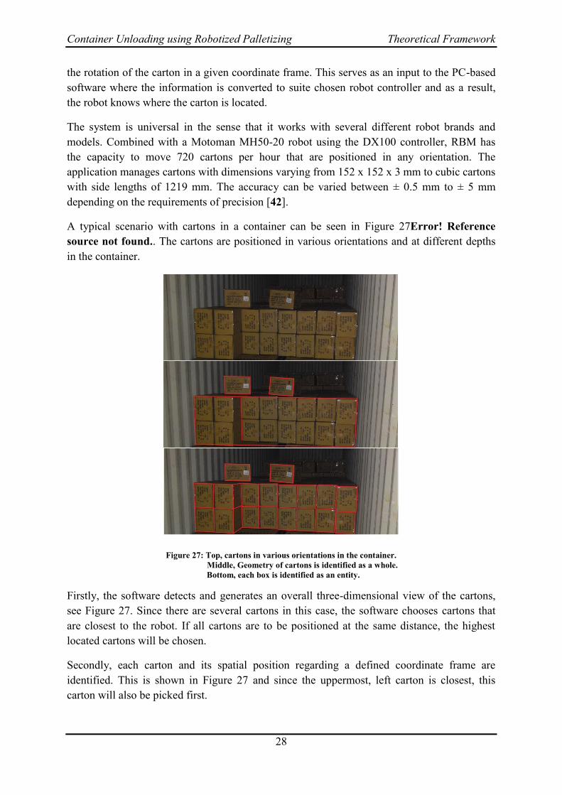
A typical scenario with cartons in a container can be seen in Figure 27Error! Reference
source not found.. The cartons are positioned in various orientations and at different depths
in the container.
Figure 27: Top, cartons in various orientations in the container.
Middle, Geometry of cartons is identified as a whole.
Bottom, each box is identified as an entity.
Firstly, the software detects and generates an overall three-dimensional view of the cartons,
see Figure 27. Since there are several cartons in this case, the software chooses cartons that
are closest to the robot. If all cartons are to be positioned at the same distance, the highest
located cartons will be chosen.
Secondly, each carton and its spatial position regarding a defined coordinate frame are
identified. This is shown in Figure 27 and since the uppermost, left carton is closest, this
carton will also be picked first.
Container Unloading using Robotized Palletizing Theoretical Framework
29
Using the calculation software, 3D Calculator, provided by Universal Robotics it is possible
to estimate at which distances the cameras should be placed in order to have desired field of
vision. As input, carton dimensions, robot reach, size of work envelope as well as location and
type of cameras are defined.
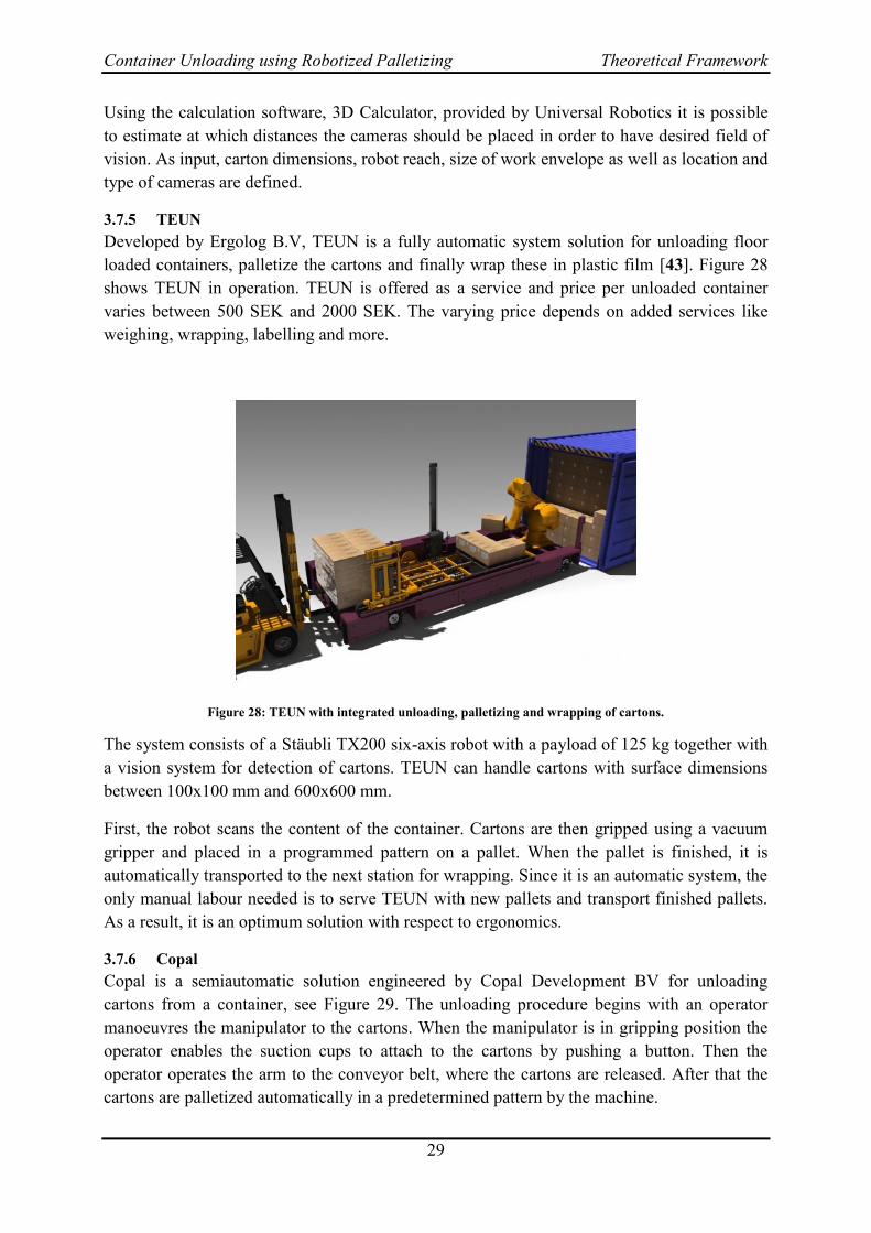
3.7.5 TEUN
Developed by Ergolog B.V, TEUN is a fully automatic system solution for unloading floor
loaded containers, palletize the cartons and finally wrap these in plastic film [43]. Figure 28
shows TEUN in operation. TEUN is offered as a service and price per unloaded container
varies between 500 SEK and 2000 SEK. The varying price depends on added services like
weighing, wrapping, labelling and more.
Figure 28: TEUN with integrated unloading, palletizing and wrapping of cartons.
The system consists of a Stäubli TX200 six-axis robot with a payload of 125 kg together with
a vision system for detection of cartons. TEUN can handle cartons with surface dimensions
between 100x100 mm and 600x600 mm.
First, the robot scans the content of the container. Cartons are then gripped using a vacuum
gripper and placed in a programmed pattern on a pallet. When the pallet is finished, it is
automatically transported to the next station for wrapping. Since it is an automatic system, the
only manual labour needed is to serve TEUN with new pallets and transport finished pallets.
As a result, it is an optimum solution with respect to ergonomics.
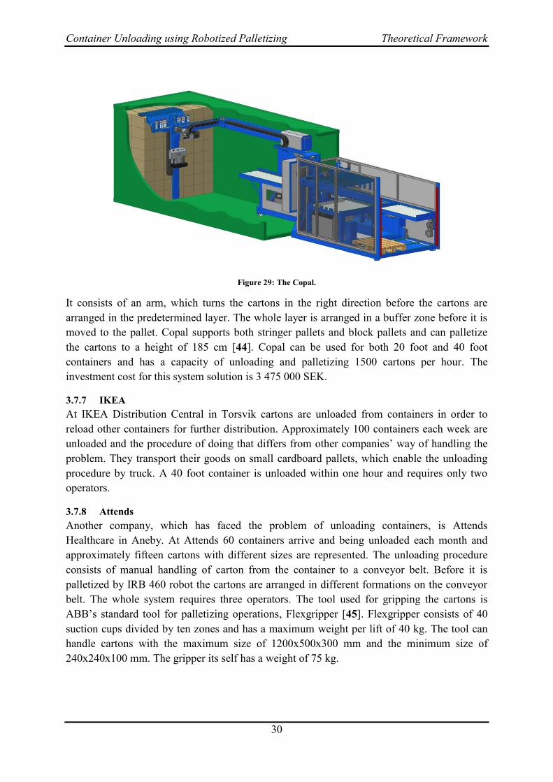
3.7.6 Copal
Copal is a semiautomatic solution engineered by Copal Development BV for unloading
cartons from a container, see Figure 29. The unloading procedure begins with an operator
manoeuvres the manipulator to the cartons. When the manipulator is in gripping position the
operator enables the suction cups to attach to the cartons by pushing a button. Then the
operator operates the arm to the conveyor belt, where the cartons are released. After that the
cartons are palletized automatically in a predetermined pattern by the machine.
Container Unloading using Robotized Palletizing Theoretical Framework
30
Figure 29: The Copal.
It consists of an arm, which turns the cartons in the right direction before the cartons are
arranged in the predetermined layer. The whole layer is arranged in a buffer zone before it is
moved to the pallet. Copal supports both stringer pallets and block pallets and can palletize
the cartons to a height of 185 cm [44]. Copal can be used for both 20 foot and 40 foot
containers and has a capacity of unloading and palletizing 1500 cartons per hour. The
investment cost for this system solution is 3 475 000 SEK.
3.7.7 IKEA
At IKEA Distribution Central in Torsvik cartons are unloaded from containers in order to
reload other containers for further distribution. Approximately 100 containers each week are
unloaded and the procedure of doing that differs from other companies’ way of handling the
problem. They transport their goods on small cardboard pallets, which enable the unloading
procedure by truck. A 40 foot container is unloaded within one hour and requires only two
operators.
3.7.8 Attends
Another company, which has faced the problem of unloading containers, is Attends
Healthcare in Aneby. At Attends 60 containers arrive and being unloaded each month and
approximately fifteen cartons with different sizes are represented. The unloading procedure
consists of manual handling of carton from the container to a conveyor belt. Before it is
palletized by IRB 460 robot the cartons are arranged in different formations on the conveyor
belt. The whole system requires three operators. The tool used for gripping the cartons is
ABB’s standard tool for palletizing operations, Flexgripper [45]. Flexgripper consists of 40
suction cups divided by ten zones and has a maximum weight per lift of 40 kg. The tool can
handle cartons with the maximum size of 1200x500x300 mm and the minimum size of
240x240x100 mm. The gripper its self has a weight of 75 kg.
Container Unloading using Robotized Palletizing Analysis
31
4 Analysis
In this chapter the analysis of the Container Unloading is presented. The first section
describes the work procedure at Elgiganten where ergonomic results are presented. In the
second section the software, PzPP, is evaluated and its applicability to the case Elgiganten is
presented. The third section covers the key factors for a solution at Elgiganten such as carton
dimensions and characteristics and gripper design. The fourth section describes systematic
evaluation of suitable solutions. Finally, two proposed solutions are presented together with a
robotized palletizing solution
Work Procedure at Elgiganten 4.1
In this section a deeper analysis of the situation at Elgiganten is presented. The situation
analysis will cover the operators’ work methods and the ergonomic situation.
The principle layout of the Container Unloading procedure is presented in Figure 1 in section
1.1. When the operator unloads the container, see number one in Figure 1, there is no lifting
aid available for facilitate the managing of cartons. The telescopic conveyor is adjustable
further into the container as the number of cartons decreases. This means that the operator
does not have to carry the cartons far distances. The conveyor is also adjustable in height in
order to minimise the required lift, but still a lifting aid would be desirable from an ergonomic
point of view. The fact that the operator is working under stressful conditions means that the
possibility to adjust the height of the conveyor belt is not frequently used. A stressful
environment usually deteriorate ergonomic situation [46]. The operator tend to stand on the
cartons when unloading the container in order to easily reach cartons high up even if it is
clearly marked that this is not allowed. If this leads to more cassations is not shown but
damaged cartons are harder to sell. During winter the operator needs to work under cold
conditions, which further affects the ergonomic situation negatively [47].
At the other end of the telescopic conveyor the cartons have to be placed in a pattern on the
pallet. This palletizing procedure also has several ergonomic shortages. The roller conveyor,
which is connected to the telescopic conveyor, is not adjustable in height, which means that a
short operator has to work at the same height as a tall operator. When the cartons are placed
on the pallet the operator needs to bend over the pallet and has to place the cartons with
precision, which is not desirable from an ergonomic point of view [48]. The filled pallet is
picked up by a truck driver, but a new pallet has to be manually handled from stack of pallet
nearby. There are lifting aids available but not used, because they are not easy enough to use
and there is no clear directive from the management team that the aids should be used. At the
palletizing operation there is no possibility to stop the conveyor which means the operator in
the container determines the work speed.
Since Elgiganten today has a telescopic conveyor at the manual workstation for Unloading
Container, it is reasonable to include it in the proposed solutions. The layout of the robot cell
should be arranged so the conveyor is moveable to another arriving gate, which it is today.

Container Unloading using Robotized Palletizing Analysis
32
When analysing the work procedure from an ergonomics point of view by the ergonomic tool,
REBA and NIOSH, the results indicate bad work conditions. The results from the REBA
analysis show that a redesign of the workstation is necessary soon or immediately because the
risk is high or very high at the moment, see Appendix - Ergonomics. Also, the method of
NIOSH confirms the bad ergonomic conditions, see Appendix - Ergonomics. According to
the method the maximum weight that is acceptable to handle in those conditions is always less
than fifteen kg. In the worst case, which is gripping cartons from the floor and gripping
cartons at a height of around 1,75 meters above floor level, the maximum acceptable weight is
around five kg. Those specified weights are lower than what a large part of the cartons weigh,
which is a severe problem for Elgiganten, see Figure 36. According to guidelines provided by
Arbetsmiljöverket, the maximum allowed weight is fifteen kg when the lift is executed 45
centimetres out from the body. The third most injured body part is the back, which is
endangered during manual managing of cartons [49].
Palletizing PowerPac 4.2
This section will firstly highlight the strong points in PzPP. Secondly various problems with
the software are given. These problems arose after having used the software and analysed it
more thoroughly. The problems have been categorized as deficiencies and teething problems.
Deficiencies are considered as more severe problems than the teething problems, since the
teething problems can most probably be fixed until the next software update release. Finally,
the applicability in the case Elgiganten and how well suited PzPP is in this case will be
analysed.
4.2.1 Strong points
There are several strong points to PzPP. The software environment in PzPP has a logical
layout with symbols that are easy to understand, see Figure 11. This makes it quick for the
user to get familiar with the different steps needed in the make of a palletizing process. The
approach of not having to do any otherwise necessary traditional text-based robot
programming is neat and makes the software easier to understand for a non-experienced user.
To be able to export product data and pallet patterns as XML-files is a time-saving feature,
since this eliminates the need to re-enter data for all products if these are to be used in another
robot station. Also, if there are many different products with various dimensions and weights,
it is not desirable to have all these product data imported in PzPP at the same time. This leads
to a lot of scrolling and searching for the right type of product in the Product Data window.
Thus, having each product as an XML-file and only importing the products needed at the time
simplifies this matter significantly.
There are options to manually edit and customise the patterns e.g. adjusting each products
individual position and orientations on the pallet see Figure 30. Pallet patterns are shown
graphically in a three-dimensional view which can be rotated and zoomed as the user wishes.
This gives good feedback and makes it easier to control and verify that the correct patterns
have been created. If pallet filling degree is an important parameter, the automatically
generated patterns can be sorted on filling degree and the maximum value can easily be
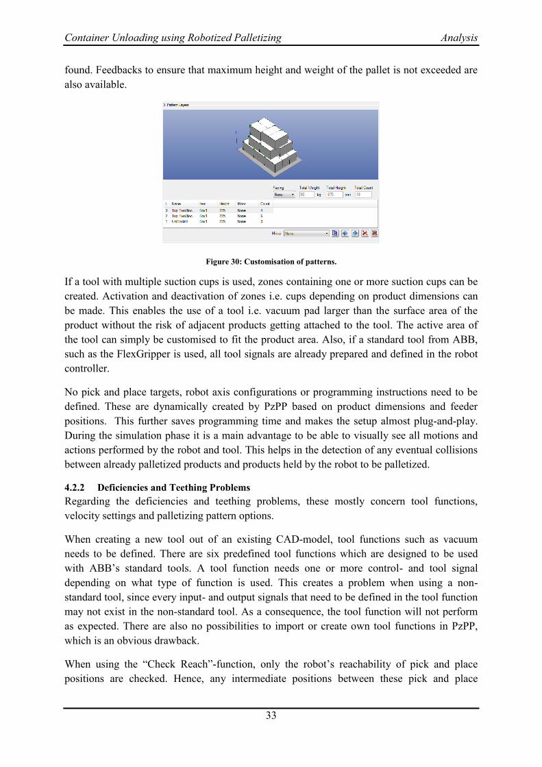
Container Unloading using Robotized Palletizing Analysis
33
found. Feedbacks to ensure that maximum height and weight of the pallet is not exceeded are
also available.
Figure 30: Customisation of patterns.
If a tool with multiple suction cups is used, zones containing one or more suction cups can be
created. Activation and deactivation of zones i.e. cups depending on product dimensions can
be made. This enables the use of a tool i.e. vacuum pad larger than the surface area of the
product without the risk of adjacent products getting attached to the tool. The active area of
the tool can simply be customised to fit the product area. Also, if a standard tool from ABB,
such as the FlexGripper is used, all tool signals are already prepared and defined in the robot
controller.
No pick and place targets, robot axis configurations or programming instructions need to be
defined. These are dynamically created by PzPP based on product dimensions and feeder
positions. This further saves programming time and makes the setup almost plug-and-play.
During the simulation phase it is a main advantage to be able to visually see all motions and
actions performed by the robot and tool. This helps in the detection of any eventual collisions
between already palletized products and products held by the robot to be palletized.
4.2.2 Deficiencies and Teething Problems
Regarding the deficiencies and teething problems, these mostly concern tool functions,
velocity settings and palletizing pattern options.
When creating a new tool out of an existing CAD-model, tool functions such as vacuum
needs to be defined. There are six predefined tool functions which are designed to be used
with ABB’s standard tools. A tool function needs one or more control- and tool signal
depending on what type of function is used. This creates a problem when using a non-
standard tool, since every input- and output signals that need to be defined in the tool function
may not exist in the non-standard tool. As a consequence, the tool function will not perform
as expected. There are also no possibilities to import or create own tool functions in PzPP,
which is an obvious drawback.
When using the “Check Reach”-function, only the robot’s reachability of pick and place
positions are checked. Hence, any intermediate positions between these pick and place

Container Unloading using Robotized Palletizing Analysis
34
positions are not checked. As a result, PzPP will state that the robot is able to perform the
whole palletizing process without complications. However, when the palletizing process is
simulated in the software or downloaded to the physical robot controller, an error message
about the inability to reach an intermediate position will occur. In order to discover this
problem the whole palletizing process has to be executed before any detection of the
mentioned problem is made, since the problem will start to occur for pallets with heights close
to the robot’s work range limit. To solve this problem, a certain amount of modifications in a
routine used in PzPP to calculate intermediate positions is needed. Due to this the purpose and
robustness of simulating the palletizing process to discover eventual problems before a
physical implementation will be made is lost. Hence, an option in the “Check Reach”-function
to enable checking the reachability of intermediate positions is desirable.
When values for robot velocities, accelerations and decelerations called motion values, are
defined in PzPP, these values are only possible to define for a certain product. If a new
product is created and the user wishes to use the same motion values as for the previous
product this cannot be done. Instead, the whole procedure must be repeated for every new
product that is created. Often it is possible to use the same velocities, accelerations and
decelerations whether a product’s dimensions and weight are similar to a product with already
defined motion values. It would therefore be more efficient to be able to create a group of
products where all products in that group use the same motion values.
The defined motion values can be tuned online at the physical robot station by using a
Tuning-function provided by PzPP on the TeachPendant. This is to create a smooth flow of
motions between the pick and place positions as well as the motions values when the robot
approach and depart defined targets. However, it is only possible to tune motion values for the
states when the robot is holding a product. Thus, motion values when the robot approaches a
product for picking or departs after placing a product is not possible to tune. Instead these
values have to be set offline in PzPP. This makes the Tuning-function a half-measure and less
capable of fulfilling desired settings.
Regarding the palletizing pattern options, a deficiency is that it is only possible to rotate a
product around the Z-axis. In addition, all products belonging to the same layer on the pallet
have to have the same orientation with regards to the X- and Y-axis. Therefore, if it is desired
to have every other layer with the product rotated around the X- and/or Y-axis, see Figure 31,
a new product has to be created. The products are identical with the only difference that the
sizes in Y and Z have been shifted, yielding a standing product instead of a lying product. As
the number of products increases so does the number of XML-files, which might be a
problem for a company like Elgiganten with a large variety of products.
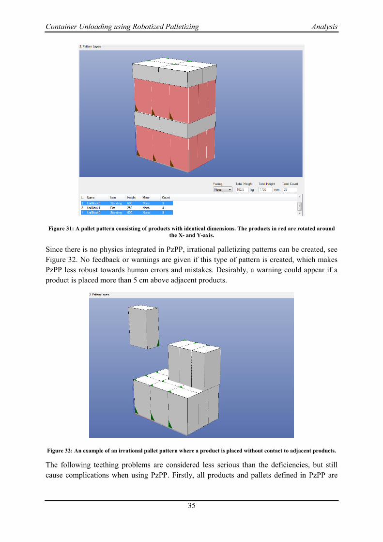
Container Unloading using Robotized Palletizing Analysis
35
Figure 31: A pallet pattern consisting of products with identical dimensions. The products in red are rotated around
the X- and Y-axis.
Since there is no physics integrated in PzPP, irrational palletizing patterns can be created, see
Figure 32. No feedback or warnings are given if this type of pattern is created, which makes
PzPP less robust towards human errors and mistakes. Desirably, a warning could appear if a
product is placed more than 5 cm above adjacent products.
Figure 32: An example of an irrational pallet pattern where a product is placed without contact to adjacent products.
The following teething problems are considered less serious than the deficiencies, but still
cause complications when using PzPP. Firstly, all products and pallets defined in PzPP are

Container Unloading using Robotized Palletizing Analysis
36
lost if the robot station is closed before PzPP is deactivated. To avoid this problem, the
following procedure has to be done:
Open station
Activate PzPP
(Work with PzPP)
Deactivate PzPP
Close station
(Quit RobotStudio)
If the user forgets to perform this procedure and a lot of different products and pallet sizes
have been defined, everything has to be defined once again, which is an outermost tedious
and time consuming work. XML-files are not affected by this teething problem.
Secondly, when creating and using a non-standard tool from a CAD-model, input and output
signals need to be specified for the tool. The number of input and output signals depend on
what functions are included in the tool. Connections of signals are made between tool and
controller, which are then saved in a so called “tool profile”. The purpose of the tool profile is
that the connections do not have to be made every time PzPP is started. However, the
problem is that this does not always work as intended. During the use of PzPP and also when
PzPP is restarted, the connections are lost which resulted in error messages and the
connection procedure had to be done again. Also, set values, such as bit values, are not
always applied for certain tool functions. Due to this, the user is uncertain which values are
current and if the tool will perform as expected. This further decreases the robustness and
reliability of the software.
Finally, the graphics in the visual simulation sometimes behave irrationally. An example of
this behaviour can be seen in Figure 33.
Figure 33: Graphics problems when running simulation in PzPP. Products and pallets appear in random places.
The aim is to create the same pallet pattern as in Figure 31. As seen, products and pallets
appear in irregular positions. Though the robot, by analysing robot movements, appear to be
picking and placing pallets and products in correct positions, the final graphical positions of
Container Unloading using Robotized Palletizing Analysis
37
these objects are not correct. Furthermore, the robot graphically fails to attach and release
products during the picking- and placing sequences. This behaviour also appears in a random
pattern and cannot be traced to any specific settings in PzPP.
Other problems that can be characterised as a more of a subjective issue is firstly that PzPP
gets slower and slower the more it is used in a session. Frequent restarts of both PzPP and
RobotStudio are needed in order to speed up the software. Secondly, due to hidden and read-
only modules and routines in PzPP, it is somewhat problematic to modify programming code
if needed. Finally, in the “Pallet Pattern” window, an option to ensure that the total pallet
height do not exceed a height set by the user. This option does not fully function, since it is
possible to set a maximum height, create a pallet pattern that exceeds this height and then
download and run the palletizing process to the real robot. From a safety viewpoint this is not
desirable.
Though PzPP simplifies steps in the palletizing procedure, such as calculations of robot
movements and pallet patterns, other steps are more difficult to modify. These steps are
mainly related to tool functions and events, where modification of the programming code
generated by PzPP is often needed.
4.2.3 Applicability in the case Elgiganten
In this section, the suitability of implementing PzPP as part of a solution for robotized
palletizing will be analysed. The strong points and deficiencies mentioned earlier in section
4.2.1 will serve as a base for this analysis.
When new products arrive at Elgiganten, these have to be defined in the “Product Data”
category and a pallet pattern has to be created. This process is done within minutes and needs
no direct prior knowledge about PzPP. Therefore it is believed that a non-experienced
operator can learn and perform these steps quickly. Regarding the pick settings, these may
cause difficulties if several products are to be picked at a time. The orientation and
displacement of the tool need to be changed, which in turn requires knowledge about how the
tool is configured and designed. Due to the unstable behaviour of PzPP, some experience in
this process is essential.
As stated in [18], no robot programming skills are needed, but it was shown during the
analysis that these skills indeed are needed. When, rather than if, a problem occurs in PzPP
knowledge in robot programming to derive and solve the problem is required. The
documentation provided with PzPP is at the moment not circumstantial, which further
complicates the troubleshooting procedure.
The aim of having operators with no previous experience in this field to create a new
palletizing procedure within 20 minutes using PzPP is therefore assumed to be not fulfilled.
Instead, one operator needs to be trained in PzPP and responsible for the creation of new
palletizing procedures. This should also create consistency and make the procedure efficient
and effective.
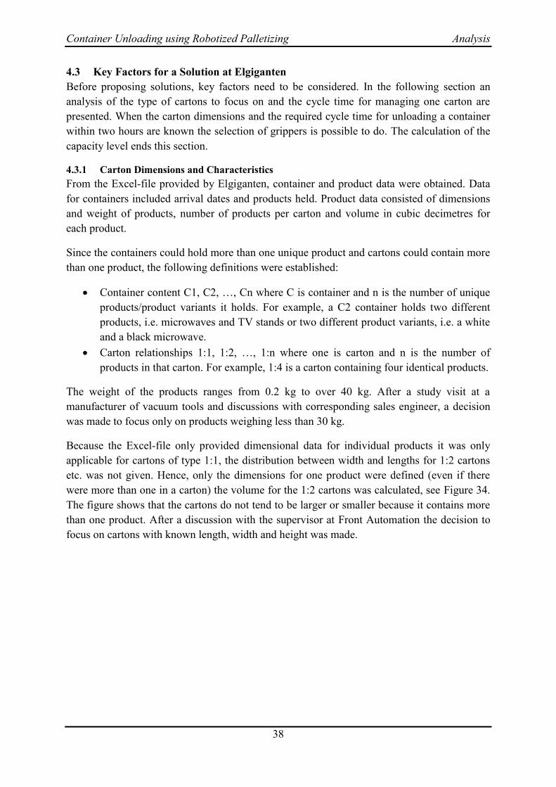
Container Unloading using Robotized Palletizing Analysis
38
Key Factors for a Solution at Elgiganten 4.3
Before proposing solutions, key factors need to be considered. In the following section an
analysis of the type of cartons to focus on and the cycle time for managing one carton are
presented. When the carton dimensions and the required cycle time for unloading a container
within two hours are known the selection of grippers is possible to do. The calculation of the
capacity level ends this section.
4.3.1 Carton Dimensions and Characteristics
From the Excel-file provided by Elgiganten, container and product data were obtained. Data
for containers included arrival dates and products held. Product data consisted of dimensions
and weight of products, number of products per carton and volume in cubic decimetres for
each product.
Since the containers could hold more than one unique product and cartons could contain more
than one product, the following definitions were established:
Container content C1, C2, …, Cn where C is container and n is the number of unique
products/product variants it holds. For example, a C2 container holds two different
products, i.e. microwaves and TV stands or two different product variants, i.e. a white
and a black microwave.
Carton relationships 1:1, 1:2, …, 1:n where one is carton and n is the number of
products in that carton. For example, 1:4 is a carton containing four identical products.
The weight of the products ranges from 0.2 kg to over 40 kg. After a study visit at a
manufacturer of vacuum tools and discussions with corresponding sales engineer, a decision
was made to focus only on products weighing less than 30 kg.
Because the Excel-file only provided dimensional data for individual products it was only
applicable for cartons of type 1:1, the distribution between width and lengths for 1:2 cartons
etc. was not given. Hence, only the dimensions for one product were defined (even if there
were more than one in a carton) the volume for the 1:2 cartons was calculated, see Figure 34.
The figure shows that the cartons do not tend to be larger or smaller because it contains more
than one product. After a discussion with the supervisor at Front Automation the decision to
focus on cartons with known length, width and height was made.
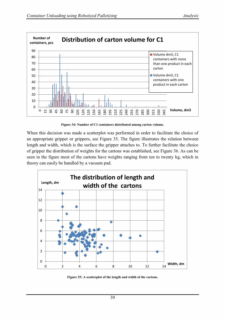
Container Unloading using Robotized Palletizing Analysis
39
Figure 34: Number of C1 containers distributed among carton volume.
When this decision was made a scatterplot was performed in order to facilitate the choice of
an appropriate gripper or grippers, see Figure 35. The figure illustrates the relation between
length and width, which is the surface the gripper attaches to. To further facilitate the choice
of gripper the distribution of weights for the cartons was established, see Figure 36. As can be
seen in the figure most of the cartons have weights ranging from ten to twenty kg, which in
theory can easily be handled by a vacuum pad.
Figure 35: A scatterplot of the length and width of the cartons.
0
10
20
30
40
50
60
70
80
90
0
15
30
45
60
75
90
10
5
12
0
13
5
15
0
16
5
18
0
19
5
21
0
22
5
24
0
25
5
27
0
28
5
30
0
31
5
33
0
34
5
Number of containers, pcs
Volume, dm3
Distribution of carton volume for C1
Volume dm3, C1containers with morethan one product in eachcarton
Volume dm3, C1containers with oneproduct in each carton
0
2
4
6
8
10
12
14
0 2 4 6 8 10 12 14
Length, dm
Width, dm
The distribution of length and width of the cartons

Container Unloading using Robotized Palletizing Analysis
40
Figure 36: Number of cartons in each weight interval.
The total number of cartons, which are manually unloaded during the last 1,5 years, were
calculated from the Excel file. This was done in order to compare number of cartons which
could be handled by the robot with the total number of cartons.
To reduce the complexity of the problem, products that would need additional handling
equipment during the palletizing process were not included in the analyses. An example of
such a product is oil-filled radiators, which have to stand upright on the smallest surface of the
carton, thus making the pallet pattern unsteady. Those radiators constitute less than 6% of the
total number of cartons.
Since it was impossible, in aspects of both time and availability, to test all different cartons
present at Elgiganten, one carton was selected for the verifications at Front Automation
mentioned in section 2.3. The carton is representative for a large number of cartons present at
Elgiganten in terms of dimensions and weight. A main difference though is that this carton
can be seen as a “worst case” scenario with regards to carton characteristics. An ideal carton
is a rigid body which do not deform during picking operations and with its weight uniformly
distributed over its volume. The carton used during the verifications was far from ideal, as can
be seen in Figure 37. Firstly, deformation of the carton’s lifting surface during picking as
indicated by the red arrows in Figure 37. As a consequence, the degree of compression of the
vacuum pad foam differs throughout the tool; see the blue arrow and lines in Figure 37.
0
50000
100000
150000
200000
250000
300000
350000
400000
0-5 5-10 10-15 15-20 20-25 25-30
Number of cartons, pcs
Weight, kg
Number of cartons for each weight intervall
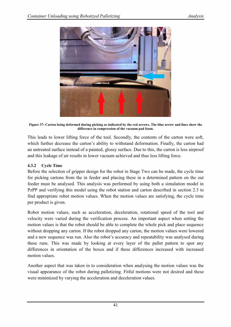
Container Unloading using Robotized Palletizing Analysis
41
Figure 37: Carton being deformed during picking as indicated by the red arrows. The blue arrow and lines show the
difference in compression of the vacuum pad foam.
This leads to lower lifting force of the tool. Secondly, the contents of the carton were soft,
which further decrease the carton’s ability to withstand deformation. Finally, the carton had
an untreated surface instead of a painted, glossy surface. Due to this, the carton is less airproof
and this leakage of air results in lower vacuum achieved and thus less lifting force.
4.3.2 Cycle Time
Before the selection of gripper design for the robot in Stage Two can be made, the cycle time
for picking cartons from the in feeder and placing these in a determined pattern on the out
feeder must be analysed. This analysis was performed by using both a simulation model in
PzPP and verifying this model using the robot station and carton described in section 2.3 to
find appropriate robot motion values. When the motion values are satisfying, the cycle time
per product is given.
Robot motion values, such as acceleration, deceleration, rotational speed of the tool and
velocity were varied during the verification process. An important aspect when setting the
motion values is that the robot should be able to complete the whole pick and place sequence
without dropping any carton. If the robot dropped any carton, the motion values were lowered
and a new sequence was run. Also the robot’s accuracy and repeatability was analysed during
these runs. This was made by looking at every layer of the pallet pattern to spot any
differences in orientation of the boxes and if these differences increased with increased
motion values.
Another aspect that was taken in to consideration when analysing the motion values was the
visual appearance of the robot during palletizing. Fitful motions were not desired and these
were minimized by varying the acceleration and deceleration values.
Container Unloading using Robotized Palletizing Analysis
42
The following motion values with respect to the given aspects mentioned above showed to be
appropriate for the 9 kg carton:
velocity= 2300 mm/s
acceleration/deceleration = 2.5 m/s2
rotational speed = 270 deg/s
When using these values, the cycle time for palletizing 20 cartons was 177 seconds or
approximately nine seconds/carton. In PzPP, the same simulated palletizing procedure yielded
a cycle time of 175 seconds. This difference is marginal and thus PzPP is regarded as reliable
for estimation of expected cycle times for other products and pallet patterns.
Given this cycle time of nine seconds/carton, it is possible to palletize 400 cartons per hour.
4.3.3 Gripper Design
In section 2.3, vacuum gripping is suitable in processes with short cycle times and for objects
that are relatively rigid. Therefore, a vacuum gripper was selected as gripping tool and this
section will describe the procedure of choosing a suitable design.
As mentioned earlier in section 4.3.1 the cartons in focus have a weight of less than 30 kg.
Cartons with weights over 30 kg constitute one percentage of the total volume and are not
included because satisfactory gripping cannot be achieved due to the carton characteristics
mentioned in section 4.3.1.
A major advantage of using vacuum pads is the ability to manage different sizes of cartons.
This flexibility is required in the case Elgiganten, where the variety of carton dimensions is
high.
In section 4.3.2 the cycle time for picking and palletize one carton was given as nine seconds.
Figure 38 shows the number of cartons per container.
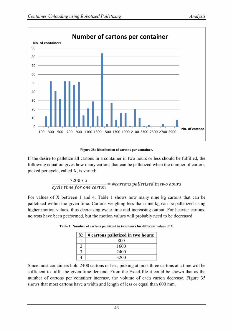
Container Unloading using Robotized Palletizing Analysis
43
Figure 38: Distribution of cartons per container.
If the desire to palletize all cartons in a container in two hours or less should be fulfilled, the
following equation gives how many cartons that can be palletized when the number of cartons
picked per cycle, called X, is varied:
For values of X between 1 and 4, Table 1 shows how many nine kg cartons that can be
palletized within the given time. Cartons weighing less than nine kg can be palletized using
higher motion values, thus decreasing cycle time and increasing output. For heavier cartons,
no tests have been performed, but the motion values will probably need to be decreased.
Table 1: Number of cartons palletized in two hours for different values of X.
X: # cartons palletized in two hours:
1 800
2 1600
3 2400
4 3200
Since most containers hold 2400 cartons or less, picking at most three cartons at a time will be
sufficient to fulfil the given time demand. From the Excel-file it could be shown that as the
number of cartons per container increase, the volume of each carton decrease. Figure 35
shows that most cartons have a width and length of less or equal than 600 mm.
0
10
20
30
40
50
60
70
80
90
100 300 500 700 900 1100 1300 1500 1700 1900 2100 2300 2500 2700 2900
No. of containers
No. of cartons
Number of cartons per container

Container Unloading using Robotized Palletizing Analysis
44
In the analysis of vacuum gripping tools the standard palletizing gripper by ABB, FlexGripper
was studied and compared with vacuum pads. The strong points of vacuum pads in
comparison with the FlexGripper are the low weight and easier maintenance. The vacuum pad
does only use one or two ejectors for each zone on the pad while the FlexGripper uses one
ejector for each suction cup. This increases the number of components, which also increase
the weight. The primary maintenance that needs to be done on a vacuum pad is cleaning and
changing the foam. When the foam is worn the whole bottom of the pad is removed and
replaced with a new one. Maintenance on the FlexGripper requires removal and changing of
suction cups. Due to the construction of the FlexGripper, see [45], the suction cups are
aligned much like berries on a straw. That means if the innermost suction cup has to be
replaced, every suction cup placed in before must be removed first. The investment cost of
having an exchangeable bottom plate is low in compared to increased cost for longer
downtime in production when FlexGripper is used.
During the verifications at Front Automation, tests were carried out in order to analyse and
find out an appropriate vacuum gripper design. It was discovered early in the tests that the
carton height on identical cartons could vary several centimetres. Since the picking position
on the in feeder is fixed in height, the robot always went to this exact position. Due to this,
and because of the sometimes lower carton heights, the carton could not attach to the vacuum
gripper. Therefore, the proposed vacuum gripper should contain a floating plate function as
mentioned in section 2.3, to make the gripper robust against differences in carton heights.
When gripping cartons at Front Automation, a vacuum level of 200 mBar was recorded. This
level differed from the vacuum levels of 600-800 mBar recorded at a manufacturer of vacuum
grippers. The difference was due to the air tubes, which were narrower at Front Automation
and therefore limited the airflow. This in turn lowered the vacuum gripper’s lifting force.
Tests were made where a carton weighing fifteen kg was lifted. The gripper could barely lift
this carton. As another test a pallet weighing fifteen kg and two cartons weighing nine kg each
was lifted, see Figure 39.
Figure 39: Vacuum gripper successfully lifts pallet weighing fifteen kg and two cartons weighing nine kg each.

Container Unloading using Robotized Palletizing Analysis
45
Figure 40: Two additional stripes of adhesive tape on carton as indicated by the red arrows.
This test was successful because the pallet was less deformed compared to lifting the carton.
The 15 kg carton was then slightly modified by adding two additional stripes of adhesive tape,
see Figure 40. Less deformation during lifting was achieved because of the additional tapes.
This resulted in a successful lift, but the carton was not gripped enough to allow any
palletizing movements without dropping.
After changing to larger air tubes, a vacuum level of 400 mBar was recorded and the fifteen
kg carton was easily lifted even without the additional tape stripes.
Another aspect discovered and analysed during the verifications was how to handle when the
area of the vacuum gripper is larger than the surface are of the carton. This caused a problem
when the carton should be placed by adjacent cartons. The already placed adjacent cartons got
attached to the vacuum gripper during the placing procedure, which resulted in displacements
of positions and orientations. An overhang of the vacuum gripper of just three cm was enough
to generate these displacements on a carton weighing nine kg.
As stated in section 4.3.1, most cartons at Elgiganten have widths and lengths less or equal
than 600x600 mm. This motivates a vacuum gripper with dimensions equal or less to the
carton dimensions. In combination with equations [1] and [2] in section 3.3.4, expertise
opinions from a manufacturer of vacuum grippers and the verifications made at Front
Automation, a recommendation for an appropriate gripper design was made.
The vacuum pad suitable for Elgiganten uses a floating plate, which works like a searcher and
compensates for variation in height of the cartons and/or pallet. The pad should have
dimensions of 400x600 mm using twin ejectors and air tubes with inner diameter of at least
ten mm to ensure that satisfactory vacuum levels can be achieved. Since the vacuum pad used
during verification is merely one-fourth in size and successfully managed cartons with poor
characteristics weighing 9 kg, the specified dimensions for the pad will work.

Container Unloading using Robotized Palletizing Analysis
46
To solve the problem with accidently attaching adjacent cartons during placing, the vacuum
gripper’s suction area should be divided into six different zones, called zoning. Each zone can
be either active (vacuum suction possible) or inactive and is independent of the other zones.
Six quadratic zones in identical size on the pad means that each zone has sides of 200 mm,
which merely a few cartons have, see Figure 35. This means the risk of attaching to another
carton while placing is minimal. The zoning is also important when placing several cartons
after each other during the same placing operation. For example, it is desirable to grip two
cartons at a time and place in an orientation which differs from the gripping orientation. This
means that the cartons cannot be placed at the same time but rather one after the other, which
requires a zoning tool.
The foam on the tool used in verifications at Front Automation had a thickness of 10 mm. The
proposed tool should use thicker foam in order to compensate for the deformations of the
carton during lifting operation. This compensation will increase the lifting force, but the
thicker foam wears out faster than thinner foam which increases the maintenance.
The ParcelRobot mentioned in 3.7.3 also use the same type of vacuum pad, which strengthen
the selection of gripper. The selection of a proven technique further increases the credibility
of the recommended gripper.
4.3.4 Capacity Level
Before proposing suitable solutions for the case Elgiganten, the appropriate capacity level
must be calculated. The early view of this case indicates about a highly automated solution for
Elgiganten. After analysing the number of incoming container and cartons per month, this
view was revised. From Figure 41 below a capacity level for the system is approximately
65 000 carton per month and shift. Setup is not considered in the calculation because this time
is hard to estimate.

Container Unloading using Robotized Palletizing Analysis
47
Figure 41: Number of cartons per month.
This calculation assumes that a container always is ready to be unloaded. The setup time
consists of docking of the trailer, securing the container, download the project from computer
to the controller in the robot cell and doing a trial run of the program.
A capacity of unloading 65 000 cartons a month, leads to that less than 400 cartons must be
unloaded each hour. This number of cartons per hour can be handled by all the solutions
presented in section 3.7. This is a lower rate than today, which is desirable from an ergonomic
perspective. If the robot is the limiting factor there is no point for the operators to stress as
today. As mentioned in section 4.1 in a stressed environment affects the operator’s physical
and mental health.
Evaluation of Solutions 4.4
Based on the factors mentioned in the previous sections, a suitable solution for Elgiganten
needed to be presented. The systematic evaluation procedure consisted of two methods, the
Pugh matrix and the Kesselring matrix. Before the evaluation procedure, the analysis of the
possible solutions is made.
4.4.1 Analysis of Existing Solutions
By using ParceLift the operator is able to unload 600 cartons per hour at normal work rate.
The ParceLift has a low investment cost and reduce the ergonomic strain on the operator. An
additional advantage of the lifting aid is the applicability to the existing conveyor belt at
Elgiganten. The tool is easy to use and learning period is short. An obvious drawback of the
ParceLift is that the operators still have to perform all the movements required for gripping
the cartons.
0
20000
40000
60000
80000
100000
120000
No. of cartons, pcs
Number of cartons per month

Container Unloading using Robotized Palletizing Analysis
48
A major advantage with Empticon compared with manual container unloading is that no
heavy loads have to be handled by the operator. This ergonomic advantage will in the long
run end up in lower cost caused by musculoskeletal disorders. Empticon has problem when
heavy cartons with a small width should be pulled, because just a few suction cups can attach
to the carton, which is not enough to pull it to the conveyor. Also the quality of the cartons is
of great importance, otherwise will not the suction cups attach to the carton. The suction cups
can also have problem to attach to the carton/-s if Empticon and the container are not aligned
parallel.
By using the ParcelRobot the ergonomic problem is eliminated, because no operator is
required. The major disadvantages of the system are the investment cost (2 500 000 SEK) and
the payback time. The number of cartons, which is unloaded, needed to be high in order to
reach a payback time in reasonable time.
For Random Box Mover the feasibility is a problem. For example, if cartons with dimensions
200x400x300 mm (width, depth, height) are placed in a work envelope equivalent to a
standard 20 feet sea container, this will result in cameras needing to be positioned at a
distance of 4 meters above the container floor. With a height of a standard container being 2
meters, the problem is obvious. Another deficiency is that RBM can only operate with USB-
cables of lengths less than 5 meters. As a consequence, the PC must be transported along with
the camera system as the robot proceeds into the container. In total, the Random Box Mover
application is a potential solution for detection of work objects in space. The advantages are
its usage of low-cost cameras and ability to adapt to various robot controller systems. Due to
the need for cameras to be placed at vertical distances beyond standard container heights, this
is a considerable drawback. Because of additional cost (robot etc.) the total cost for this
system is high.
The major advantage of using TEUN is that just a truck driver, which is loading and
unloading the machine with an empty respective full pallet, is required. One drawback of the
solution is that the system is offered as a service and therefore is the payback time difficult to
calculate.
At IKEA the ergonomic problems are low in comparison to Elgiganten because the unloading
procedure is managed by trucks. Unfortunately, the cardboard pallets used are not applicable
to Elgiganten because it is not cost-effective as stated in section 3.1.1. The number of
unloaded containers at IKEA is extensively larger than for Elgiganten. A major advantage of
this solution is that it is not sensitive for high product variety, which IKEA also has.
At Attends the number of arriving containers are about 60 a month, which is comparable with
Elgiganten. However, the number of variants is fewer and the weight of the cartons is lower at
Attends than at Elgiganten. Large part of the system solution is applicable at Elgiganten but
the gripper is not, see section 4.3.3.
Generally, an advanced solution for container unloading at Elgiganten is not suitable because
of the low number of arriving containers and their current level of automation is low.
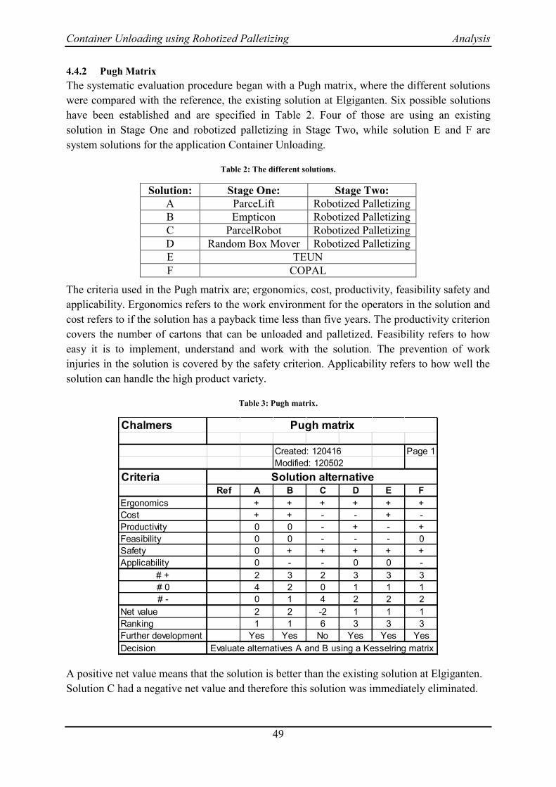
Container Unloading using Robotized Palletizing Analysis
49
4.4.2 Pugh Matrix
The systematic evaluation procedure began with a Pugh matrix, where the different solutions
were compared with the reference, the existing solution at Elgiganten. Six possible solutions
have been established and are specified in Table 2. Four of those are using an existing
solution in Stage One and robotized palletizing in Stage Two, while solution E and F are
system solutions for the application Container Unloading.
Table 2: The different solutions.
Solution: Stage One: Stage Two:
A ParceLift Robotized Palletizing
B Empticon Robotized Palletizing
C ParcelRobot Robotized Palletizing
D Random Box Mover Robotized Palletizing
E TEUN
F COPAL
The criteria used in the Pugh matrix are; ergonomics, cost, productivity, feasibility safety and
applicability. Ergonomics refers to the work environment for the operators in the solution and
cost refers to if the solution has a payback time less than five years. The productivity criterion
covers the number of cartons that can be unloaded and palletized. Feasibility refers to how
easy it is to implement, understand and work with the solution. The prevention of work
injuries in the solution is covered by the safety criterion. Applicability refers to how well the
solution can handle the high product variety.
Table 3: Pugh matrix.
A positive net value means that the solution is better than the existing solution at Elgiganten.
Solution C had a negative net value and therefore this solution was immediately eliminated.
Chalmers
Created: 120416 Page 1
Modified: 120502
CriteriaRef A B C D E F
Ergonomics + + + + + +
Cost + + - - + -
Productivity 0 0 - + - +
Feasibility 0 0 - - - 0
Safety 0 + + + + +
Applicability 0 - - 0 0 -
# + 2 3 2 3 3 3
# 0 4 2 0 1 1 1
# - 0 1 4 2 2 2
Net value 2 2 -2 1 1 1
Ranking 1 1 6 3 3 3
Further development Yes Yes No Yes Yes Yes
Decision Evaluate alternatives A and B using a Kesselring matrix
Solution alternative
Pugh matrix
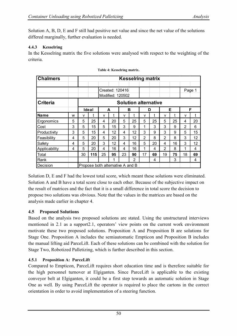
Container Unloading using Robotized Palletizing Analysis
50
Solution A, B, D, E and F still had positive net value and since the net value of the solutions
differed marginally, further evaluation is needed.
4.4.3 Kesselring
In the Kesselring matrix the five solutions were analysed with respect to the weighting of the
criteria.
Table 4: Kesselring matrix.
Solution D, E and F had the lowest total score, which meant these solutions were eliminated.
Solution A and B have a total score close to each other. Because of the subjective impact on
the result of matrices and the fact that it is a small difference in total score the decision to
propose two solutions was obvious. Note that the values in the matrices are based on the
analysis made earlier in chapter 4.
Proposed Solutions 4.5
Based on the analysis two proposed solutions are stated. Using the unstructured interviews
mentioned in 2.1 as a support2.1, operators’ view points on the current work environment
motivate these two proposed solutions. Proposition A and Proposition B are solutions for
Stage One. Proposition A includes the semiautomatic Empticon and Proposition B includes
the manual lifting aid ParceLift. Each of these solutions can be combined with the solution for
Stage Two, Robotized Palletizing, which is further described in this section.
4.5.1 Proposition A: ParceLift
Compared to Empticon, ParceLift requires short education time and is therefore suitable for
the high personnel turnover at Elgiganten. Since ParceLift is applicable to the existing
conveyor belt at Elgiganten, it could be a first step towards an automatic solution in Stage
One as well. By using ParceLift the operator is required to place the cartons in the correct
orientation in order to avoid implementation of a steering function.
Chalmers
Created: 120416
Modified: 120502
Criteria
Name w v t v t v t v t v t v t
Ergonomics 5 5 25 4 20 5 25 5 25 5 25 4 20
Cost 3 5 15 5 15 3 9 1 3 3 9 2 6
Productivity 3 5 15 4 12 4 12 3 9 3 9 5 15
Feasibility 4 5 20 5 20 3 12 2 8 2 8 3 12
Safety 4 5 20 3 12 4 16 5 20 4 16 3 12
Applicability 4 5 20 4 16 4 16 1 4 2 8 1 4
Total 30 115 25 95 23 90 17 69 19 75 18 69
Rank 1 2 4 3 4
Decision Propose both alternative A and B
Kesselring matrix
Solution alternative
Ideal A B D E F
Page 1

Container Unloading using Robotized Palletizing Analysis
51
ParceLift has been successfully implemented at Posten Logistics in Orebro, where a large
variety of cartons are handled every day. The relatively low investment cost and the
applicability to the existing conveyor belt are two things which support this solution.
The bad ergonomic postures are not improved by implementing ParceLift, but the risk of
musculoskeletal disorders is decreased by lowering the workloads, see Appendices NIOSH
Analysis Future State and REBA Analysis Future State.
4.5.2 Proposition B: Empticon
The major advantage of implementing Empticon is the ergonomic benefits. The operator does
not have to manually lift the cartons but operates the conveyor to the cartons. When the
cartons are placed on the conveyor belt, a steering function is needed in order to move the
cartons to a predetermined position. This position needs to be the same for all cartons since
the robot’s picking position is constant. The orientation of the cartons in the container will be
the same on the conveyor belt, because it is not possible by Empticon to re-orient the cartons.
To be a skilled driver of Empticon, quite a long time of practice is required. The personnel
turnover at Elgiganten is at the moment relatively high, probably because of the heavy lifts.
However, if Empticon is to be successfully implemented at Elgiganten, a group of operators
need to be educated and trained to operate the machine.
An investment in Empticon will release the existing conveyor belt, which could be used for
other gates during the peaks in the seasonal variation.
4.5.3 Robotized Palletizing
The robotized palletizing procedure begins with the carton being positioned along two sides,
see Figure 42. For the palletizing procedure this positioning is important, because if the carton
is not oriented in the same way every time the pallet pattern will be disordered

Container Unloading using Robotized Palletizing Analysis
52
Figure 42: Illustration of the robotized palletizing procedure from RobotStudio.
When the positioning is secured, the robot picks the carton by the vacuum pad and palletizes
it on the pallet. As the whole pallet is done, it is transported to the out feeder and a new pallet
from a pallet magazine arrives to the palletizing position. From the out feeder, the ready pallet
is transported by truck to a machine where it is wrapped in plastic film.
One option could be to implement the stretch wrap machine into the cell, but this option is not
chosen because of delimitations earlier in the project.
In construction of a robot cell the safety issues need to be considered. Fences need to be
arranged so no employees are able to enter the cell while the robot is operating. Also, the
fences must not obstruct the robot.

Container Unloading using Robotized Palletizing Discussion
53
5 Discussion
At Elgiganten today the ergonomic strain on the operators is obvious. From the ergonomic
analyses a redesign of the work stations are required as soon as possible. Both Proposition A
and Proposition B decrease the ergonomic strain on the operator, which has been an important
factor in the selection of appropriate solutions.
Both propositions have their strengths and weaknesses. By using Empticon in Stage One a
trained and skilled operator can unload 600 cartons per hour. If ParceLift is used in Stage One
this limitation estimated to 700 cartons per hour. The robotized palletizing in Stage Two has a
limitation of 400 cartons per hour when just one carton is picked and palletized at a time. If
more cartons are palletized at the same time, the cycle time per carton will decrease and
higher productivity is achieved. It is important that Stage Two is the limiting factor.
Otherwise, the stress on operators in Stage One will increase which in turn will increase the
ergonomic strain.
When analysing other similar cases of Container Unloading, it is obvious that the proposed
solutions are successfully implemented, which strengthens the solutions. At Attends, manual
unloading containers and palletizing cartons by a robot is performed. Approximately fifteen
containers each week are unloaded, which is a volume that is comparable to that at
Elgiganten. The reason for not using lifting aids when unloading the container is because of
the low weight of the cartons. According to Attends it is preferable and economically viable
to implement robotized palletizing even though the carton weights are not as high as in the
case Elgiganten. During the study visit at IKEA Distribution Central at Torsvik another
interesting Container Unloading procedure was discovered. At IKEA all containers arrive
with cartons already palletized on cardboard pallets, which means whole pallets can be
unloaded directly by truck. Even though the solution was interesting to analyse further, this
type of solution was not considered in the case Elgiganten. This was because of the perquisite
from Elgiganten that the cartons will arrive in containers as per today.
Inputs from the study visits at Attends have affected the selection of gripper. An obvious
problem with FlexGripper is the suction cups ability to compensate for different height of the
products. This deficiency was adjusted by higher suctions cups, but these in turn lead to
undesirable swinging motions during acceleration or deceleration. At Attends the variety of
carton dimensions is low in compared with Elgiganten. Higher variation of sizes of the
cartons needs a more flexible gripper. Thus, selecting a vacuum pad was motivated. When
designing a gripper, the variation in carton quality and its ability to withstand deformation are
an important factor to consider. At Elgiganten the carton quality differs between the products.
Cartons that contain more than one product often have worse quality.
When it comes to managing the seasonal variations at Elgiganten, the best way from an
ergonomic perspective is to add extra shifts. This will also increase the utilization rate of the
robot. Another alternative is to use two operators in Stage One and decrease the cycle time for
the robot by picking several cartons at a time. In the proposed solution, the robot is the bottle

Container Unloading using Robotized Palletizing Discussion
54
neck which is preferable from an ergonomic point of view. If even higher capacity is required
other gates can be used manually as today.
The implementation of robotized palletizing at Elgiganten will require efforts from
Elgiganten. To get the solution applicable, an operator with technical interests is needed and
he or she should be responsible preparations and verifications needed when new products
arrive. The teething problems in PzPP need to be eliminated before the software is robust
enough to implement at Elgiganten. Also, operators should be trained and skilled in PzPP in
order to solve eventual problems that arise. A possibility would be to implement robotized
palletizing for approximately five products that represent a major share of the total volume.
The number of products can then be increased after the first five products are being palletized
without difficulties. In that way, operators get accustomed to both software and the new way
of working.
Additional factors that need to be considered on implementation are carton identification
systems and conveyor buffers. An identification system, for example bar code reader, is
needed if different cartons are to be on the conveyor at the same time. This is to inform the
robot about which carton is to be picked. For picking several cartons at a time, a buffer system
is needed to provide the robot with the correct number of cartons.
The consequences for the physical workload and musculoskeletal disorders will decrease,
according to REBA, when implementing lifting aids and robotized palletizing. Since the
characteristics of labour shifts from manual work to partially manual work, the ergonomic
strain will decrease [50]. The implementation will result in lower movement velocities, which
also decrease the ergonomic strains.
By using ParceLift in Stage One the operators’ complaint of lower back pain will decrease
[36]. At a case study at Posten in Orebro the absence due to illness was lowered by 5-10 %.
Since Elgiganten today hires its personnel through a staffing company, the absence due to
illness is not known. This does not mean that this is not a problem for Elgiganten. If it is
discovered that operators from the staffing company got musculoskeletal disorders because of
the bad ergonomic work stations at Elgiganten, this is a serious problem.
On the market today interesting solutions for unloading containers exist and therefore the
choice of analysing them was made. As mentioned before, not all of them are suitable to
Elgiganten, but still interesting if the number of arriving cartons per month at Elgiganten
increases. The method to study existing solutions instead of developing totally new concept
has its strengths and weaknesses. One strongpoint of studying existing solutions is that the
technique is well-tried and tested in reality. If a new concept is proposed, this concept will not
be tested in full production, which is a deficiency compared to the existing solutions. A
weakness of focusing on existing solutions is the limitation of the possible solutions for
Elgiganten. To increase the number possible solutions for Elgiganten further existing
solutions of other business could have been analysed.

Container Unloading using Robotized Palletizing Conclusions
55
6 Conclusion
In this section conclusions drawn from the analyses made and from the study in general are
presented.
For operators with no experience in robot programming, it is not likely that it will be possible
to setup a new palletizing procedure within 20 minutes using PzPP. Instead, Elgiganten need
to assign operators educated and trained in PzPP for this task.
It will be feasible and cost-effective to use robotized palletizing at Elgiganten for products
weighing less than 30 kg and side lengths of 600 mm when using the proposed vacuum pad.
The productivity will be unchanged or improved and depends on how well Elgiganten is able
to utilize the robot cell. A capacity of unloading 65 000 cartons a month will be possible if the
proposed solutions are implemented. Due to the varying quality of the cartons and the ability
to withstand deformation during lifting it is difficult to predict if it is possible to unload
containers within two hours. This is because the carton quality dictates the maximum
permitted motion values and hence the cycle time.
The work environment with regards to ergonomics will be improved significantly as shown
by the analyses if the proposed solutions are implemented. In Stage One, the workload is
reduced resulting in facilitation of unloading cartons. In Stage Two, the ergonomic problems
are completely eliminated.
The proposed solutions for Stage One and the robotized solution for Stage Two are
appropriate levels of automation for Elgiganten. Due to the manual work procedure at
Elgiganten with automation present, fully automatic solutions would not have been suitable
and was therefore not proposed. If and when the conditions change in terms of containers
handled per year, other analysed solutions can be of interest.

Container Unloading using Robotized Palletizing References
56
References
[1] Elgiganten. (2011, Dec) Detta är Elgiganten - Elgiganten. [Online].
http://www.elgiganten.se/cms/c-l7EKeQuwRGUAAAEo9AtgPisz/detta-ar-elgiganten
[2] Previa. (2012) Elgiganten - Previa. [Online].
http://www.previa.se/previa/templates/case____3854.aspx
[3] ABB Robotics. (2011, March) ABB Robotics. [Online].
http://www05.abb.com/global/scot/scot241.nsf/veritydisplay/95c9da16ac8a4d92c12578
38002bf7ef/$file/ROB0206EN_A_IRB%20460%20data%20sheet.pdf
[4] Global Finance. (2010, April) Countries with the Highest GDP Growth 2000-2010.
[Online]. http://www.gfmag.com/tools/global-database/economic-data/10304-countries-
with-the-highest-gdp-growth-2000-2010.html#axzz1kx7xVGPM
[5] UNPD World Bank. (1998) Private per-capita consumption. [Online].
http://atlas.aaas.org/natres/intro_popups.php?p=percap
[6] Dr. Jean-Paul Rodrigue. (2012) THE GEOGRAPHY OF TRANSPORT SYSTEMS.
[Online]. http://people.hofstra.edu/geotrans/eng/ch3en/conc3en/transcost.html
[7] World Shipping Council. (2012) World Shipping Council. [Online].
http://www.worldshipping.org/about-the-industry/containers/global-container-fleet
[8] Dr. Jean-Paul Rodrigue. (2012) THE GEOGRAPHY OF TRANSPORT SYSTEMS.
[Online]. http://people.hofstra.edu/geotrans/eng/ch3en/conc3en/containerfleet.html
[9] EPAL. (2012, January) EPAL Pallet System. [Online]. http://www.epal-
pallets.de/uk/produkte/paletten.php
[10] Gaël Raballand and Enrique Aldaz-Carroll, "HOW DO DIFFERING STANDARDS
INCREASE TRADE COSTS? THE CASE OF PALLETS," no. 3519, 2005.
[11] (2009, March) ISO - International Organization for Standardization. [Online].
http://www.iso.org/iso/iso_catalogue/catalogue_tc/catalogue_detail.htm?csnumber=305
24
[12] International Standards for Phytosanitary Measures. (2009) Regulation of wood
packaging material in international trade. [Online].
http://www.ispm15.com/ISPM15_Revised_2009.pdf
[13] Dr. Jean-Paul Rodrigue. (2012) THE GEOGRAPHY OF TRANSPORT SYSTEMS.
[Online].
Container Unloading using Robotized Palletizing References
57
http://people.hofstra.edu/geotrans/eng/ch4en/conc4en/tbl_containertransloading.html
[14] Mikell P. Groover, "Industrial Robotics," in Automation, Production Systems, and
Computer-Integrated Manufacturing, Holly Stark, Ed. New Yersey, USA: Pearson
Prentice Hall, 2008, ch. 8, pp. 229-265.
[15] ABB, "Special Report: Robotics," ABB Review , March 2005.
[16] Global Robots FZE. (2012, May) Global Robots FZE. [Online].
http://www.globalrobots.ae/robot_guide/images/ABBIRB6400M94Amovements.jpg
[17] atsi. (2012, May) http://www.atsi.cc/articulating-arm-robot.htm. [Online].
https://encrypted-
tbn0.google.com/images?q=tbn:ANd9GcQbave24aFG64zUP4Qt_Qyecz0AB0B-
US5XDlnBk0FQcBRUCkw_Mw
[18] ABB Robotics. (2011, March) RobotStudio Palletizing PowerPac Industrial software
products. [Online].
http://www05.abb.com/global/scot/scot241.nsf/veritydisplay/8194b916f2b7c1e7c12578
64004a3dc4/$file/ROB0211EN_A_Palletizing%20PowerPac%20data%20sheet_final.p
df
[19] ABB Robotics. (2007) ABB Robot Manuals. [Online].
http://www.abbrobots.co.uk/files/3HAC025829-001_rev-_en.pdf
[20] ABB Robotics. (2011, June) RobotStudio Palletizing PowerPac highlights ABB
expanded palletizing portfolio at Interpack 2011. [Online].
http://www.prlog.org/11544365-robotstudio-palletizing-powerpac-highlights-abb-
expanded-palletizing-portfolio-at-interpack-2011.html
[21] ABB. (2011, November) ABB Palletizing Software - Programvara (Robotics). [Online].
http://www05.abb.com/global/scot/scot352.nsf/veritydisplay/102e0a70c151c493c12579
440034d13d/$file/PalletizingPowerPacUserManual.pdf
[22] Gareth J Monkman, Stefan Hesse, Steinmann Ralf, and Schunk Henrik, Robot
Grippers. Weinheim: Wiley-Vch Verlag GmbH & Co, 2007.
[23] Schmalz. (2011, September) Schmalz. [Online].
http://www.schmalz.com/data/kataloge/01_VT/gb/01_Catalog-Components_EN.pdf
[24] (2005) Protech. [Online]. http://www.protech.hu/robotos_megfogok.pdf
[25] Unigripper. (2012) UniGripper Intelligent Vacuum. [Online].
http://unigripper.com/index.php/en/functions
Container Unloading using Robotized Palletizing References
58
[26] Bosch Rexroth. (2012, February) Rexroth Bosch Group. [Online].
http://www.boschrexroth.com/computation/vacuum/help_safety.jsp
[27] Mikell P. Groover, "Inspection Technology," in Automation, Production Systems, and
Computer-Integrated Manufacturing, Holly Stark, Ed. New Yersey, USA: Pearson
Prentice Hall, 2008, ch. 22, pp. 674-712.
[28] Stephan Hussmann, Thorsten Ringbeck, and Bianca Hagebeuker, "A Performance
Review of 3D TOF Vision Systems in Comparison to Stereo Vision Systems," in Stereo
vision. Croatia: In-Teh, 2008, ch. 7, pp. 103-120.
[29] Stephan Hussmann and Thorsten Liepert, "Three-Dimensional TOF Robot Vision
System," IEEE TRANSACTIONS ON INSTRUMENTATION AND MEASUREMENT,
vol. 58, no. 1, pp. 141-146, January 2009.
[30] Bernd Scholz-Reiter, Hendrik Thamer, and Claudio Uriarte, "Towards 3D Object
Recognition for Universal Goods in Logistic," in Advances in Communications,
Computers, Systems, Circuits and Devices, Tenerife, 2010, pp. 250-254.
[31] Anna-Lisa Osvalder, Linda Rose, and Stig Karlsson, "Metoder," in Arbete och teknik på
människans villkor, Gunnar Lagerström, Ed. Stockholm, Sverige: Prevent, 2008, ch. 9,
pp. 463-610.
[32] Sue Hignett and Lynn McAtamney, "Rapid Entire Body Assessment (REBA)," Applied
Ergonomics, vol. 31, pp. 201-205, June 1999.
[33] Thomas R. Waters, Vern Putz-Anderson, and Arun Garg, APPLICATIONS MANUAL
FOR THE REVISED NIOSH LIFTING EQUATION. Cincinnati, Ohio: U.S.
DEPARTMENT OF HEALTH AND HUMAN SERVICES, 1994.
[34] Peter Blanchonette, "Jack Human Modelling Tool: A Review," Air Operations
Division; Defence Science and Technology Organisation, Melbourne, Technical Report
DSTO-TR-2364, 2010.
[35] Vaculex. (2011) Vaculex - Working with ease. [Online].
http://www.vaculex.com/Products/Lifters/VaculexParceLift.aspx
[36] Vaculex AB. (2011) Case Study - Posten Logistics Örebro. [Online].
http://www.vaculex.com/References/Casestudies/CasestudyPostenLogistics%C3%96re
bro.aspx
[37] Johan Fogelberg, Sales Support Vaculex, 2012, Email.
[38] Empticon. (2011) Empticon by Univeyor. [Online].
Container Unloading using Robotized Palletizing References
59
http://www.empticon.com/media/6136/empticon-uk-lowress.pdf
[39] Wolfgang Echelmeyer, Alice Kirchheim, and Eckhard Well, "Robotics-Logistics:
Challenges for Automation of Logistic Processes," in International Conference on
Automation and Logistics, Qingdao, September 2008, pp. 2099-2103.
[40] B Scholz-Reiter, W Echelmeyer, and E Wellbrock, "Development of a Robot-Based
System for Automated Unloading of Variable Packages out of Transport Units and
Containers," in International Conference on Automation and Logistics, Qingdao, China,
2008, pp. 2766-2770.
[41] Wolfgang Echelmeyer, Alice Kirchheim, Hülya Akbiyi, and Marco Bonini,
Performance Indicators for Robotics Systems in Logistics Applications, July 2011,
IROS Workshop on Metrics and Methodologies for Autonomous Robot Teams in
Logistics (MMART-LOG), 2011.
[42] Universal Robotics. (2011, January) Random Box Moving | Universal Robotics.
[Online]. http://www.universalrobotics.com/random-box-mover
[43] TEUN. (2011) TEUN.com - TEUN takes a load off your hands. [Online].
www.teun.com/en
[44] Copal Development BV. copal-development.nl. [Online]. http://www.copal-
development.nl/folders/Folder_Container_unloader.pdf
[45] (2011, March) ABB Robotics. [Online].
http://www05.abb.com/global/scot/scot241.nsf/veritydisplay/12282933368eeeefc12578
5000576ea9/$file/ROB0210EN_A_FlexGripper%20Vacuum%20data%20sheet_final.p
df
[46] Ingela Thylefors, "Psykosocial arbetsmiljö," in Arbete och Teknik på människans
villkor. Stockholm, Sweden: Prevent, 2008, ch. 1, pp. 19-129.
[47] Mats Boghard et al., "Fysikaliska faktorer," in Arbete och teknik på människans villkor.
Stockhom, Sverige: Prevent, 2008, ch. 5, pp. 191-337.
[48] Nokubonga Slindele Ngcamu, "AWKWARD WORKING POSTURES AND
PRECISION PERFORMANCE AS AN EXAMPLE OF THE RELATIONSHIP
BETWEEN ERGONOMICS AND PRODUCTION QUALITY," Department of
Human Kinetics and Ergonomics, Grahamstown, Master Thesis 2009.
[49] Arbetsmiljöverket, "Arbetsskador 2010," Arbetsmiljöverket, Statistic report ISSN 1652-
1110, 2011.

Container Unloading using Robotized Palletizing References
60
[50] Istvan Balogh, Kerstina Ohlsson Ohlsson, Gert-Åke Hansson, Tomas Engström, and
Staffan Skerfving, "Increasing the degree of automation in a production system:
Consequences for the physical workload," Industrial Ergonomics, no. 36, pp. 353-365,
Febraury 2006.
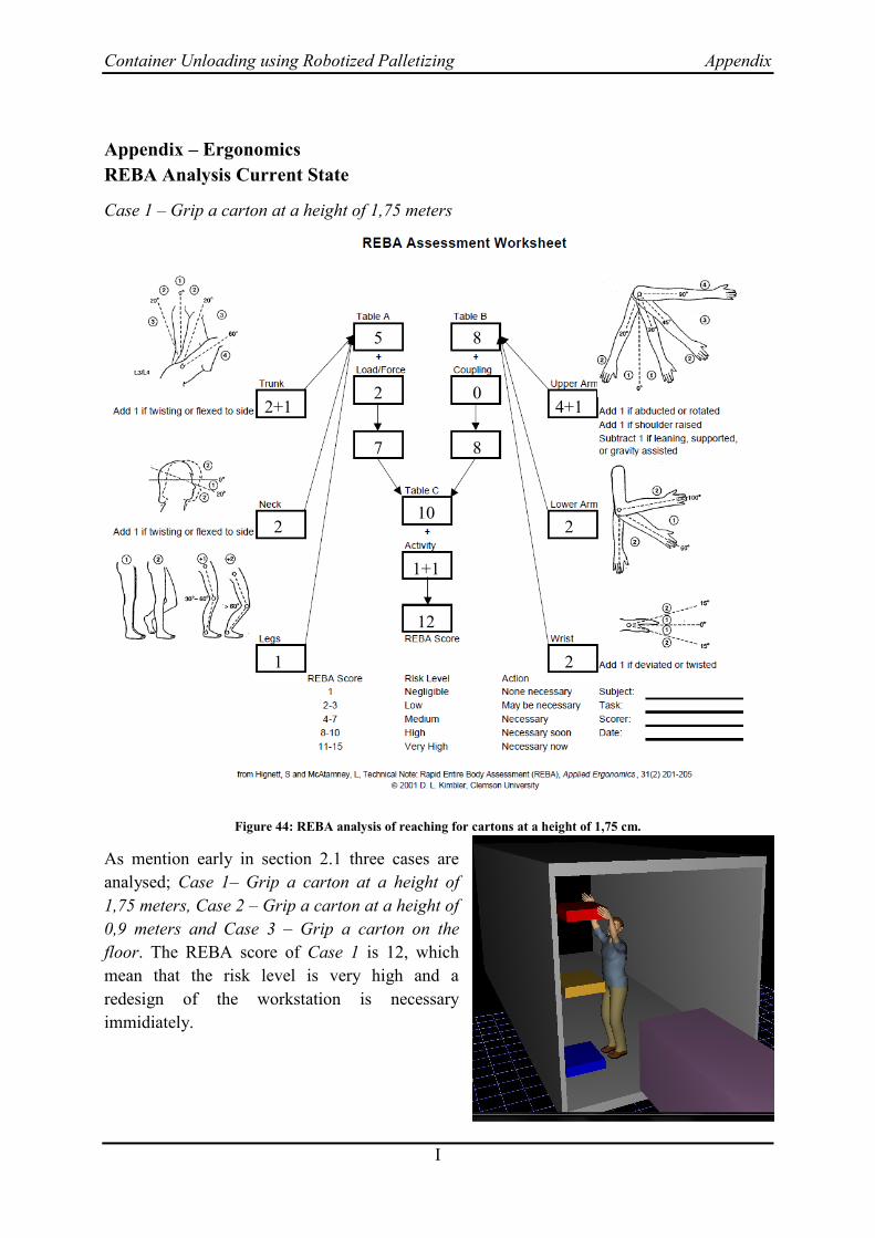
Container Unloading using Robotized Palletizing Appendix
I
Appendix – Ergonomics
REBA Analysis Current State
Case 1 – Grip a carton at a height of 1,75 meters
Figure 44: REBA analysis of reaching for cartons at a height of 1,75 cm.
As mention early in section 2.1 three cases are
analysed; Case 1– Grip a carton at a height of
1,75 meters, Case 2 – Grip a carton at a height of
0,9 meters and Case 3 – Grip a carton on the
floor. The REBA score of Case 1 is 12, which
mean that the risk level is very high and a
redesign of the workstation is necessary
immidiately.
2+1
2
1
7
2
5 8
0
8
10
1+1
12
4+1
2
2
Figure 43: Illustration from Jack.

Container Unloading using Robotized Palletizing Appendix
II
Case 2 – Grip a carton at a height of 0,9 meters
Figure 45: REBA analysis of gripping cartons at a height of 0,9 meters.
For Case 2 is the REBA Score 9, which mean a
redesign of the workstation is required soon
because the risk level is high.
2
2
1
6
2
4 4
0
4
7
1+1
9
3
2
1
Figure 46:Illustration from Jack.

Container Unloading using Robotized Palletizing Appendix
III
Case 3 – Grip a carton on the floor
Figure 47: REBA analysis of gripping cartons on the floor.
REBA Score is 13, which mean that the work
posture is risky and has to be avoided. In this work
posture a lifting aid would be helpful in order to
reduce the load and the risk of injuries in the lower
back.
4
2
1+2
9
2
7 7
0
7
11
1+1
13
4+1
2
1
Figure 48: Illustration from Jack.

Container Unloading using Robotized Palletizing Appendix
IV
Table 5: Tables for REBA.
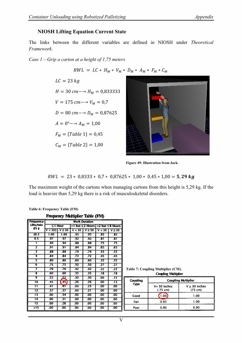
Container Unloading using Robotized Palletizing Appendix
V
NIOSH Lifting Equation Current State
The links between the different variables are defined in NIOSH under Theoretical
Framework.
Case 1 – Grip a carton at a height of 1,75 meters
{ }
{ }
The maximum weight of the cartons when managing cartons from this height is 5,29 kg. If the
load is heavier than 5,29 kg there is a risk of musculoskeletal disorders.
Figure 49: Illustration from Jack.
Table 6: Frequency Table (FM)
Table 7: Coupling Multiplier (CM).

Container Unloading using Robotized Palletizing Appendix
VI
Case 2 – Grip a carton at a height of 0,9 meters
{ }
{ }
To secure that no risk of musculoskeletal disorders when gripping cartons at a height of 0,9
meters the maximum weight is 14,17 kg.
Figure 50: Illustration from Jack.
Table 8: Frequency Table (FM)
Table 9: Coupling Multiplier (CM).
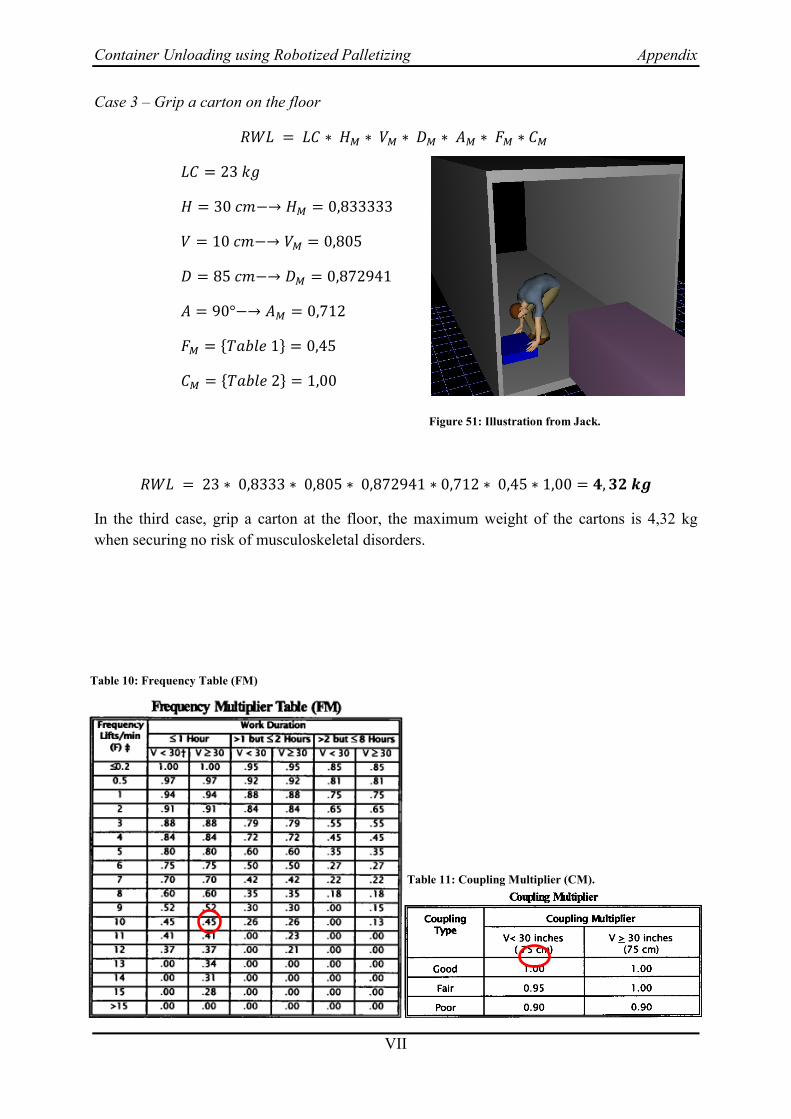
Container Unloading using Robotized Palletizing Appendix
VII
Case 3 – Grip a carton on the floor
{ }
{ }
In the third case, grip a carton at the floor, the maximum weight of the cartons is 4,32 kg
when securing no risk of musculoskeletal disorders.
Figure 51: Illustration from Jack.
Table 10: Frequency Table (FM)
Table 11: Coupling Multiplier (CM).

Container Unloading using Robotized Palletizing Appendix
VIII
REBA Analysis Future State
Case 1 – Grip a carton at a height of 1,75 meters
Figure 53: REBA analysis of reaching for cartons at a height of 1,75 cm.
The analysis of the Future State included the
same three cases as the Current State;
Case 1– Grip a carton at a height of 1,75 meters,
Case 2 – Grip a carton at a height of 0,9 meters
and Case 3 – Grip a carton on the floor. By using
ParceLift in Stage One the REBA score of Case 1
is 4, which mean that risk level is dramatically
lowered to a medium level. Redesign of the
workstation is necessary, but close to may be
necessary.
1
2
1
1
0
1 4
0
4
2
1+1
4
4
1
1
Figure 52: Illustration from Jack.
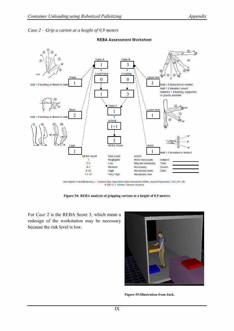
Container Unloading using Robotized Palletizing Appendix
IX
Case 2 – Grip a carton at a height of 0,9 meters
Figure 54: REBA analysis of gripping cartons at a height of 0,9 meters.
For Case 2 is the REBA Score 3, which mean a
redesign of the workstation may be necessary
because the risk level is low.
1
2
1
1
0
1 3
0
3
1
1+1
3
3
1
1
Figure 55:Illustration from Jack.

Container Unloading using Robotized Palletizing Appendix
X
Case 3 – Grip a carton on the floor
Figure 56: REBA analysis of gripping cartons on the floor.
REBA Score is 7, which mean that the work posture
is at a medium risk level.
3
2
2
5
0
5 4
0
4
5
1+1
7
4
1
1
Figure 57: Illustration from Jack.

Container Unloading using Robotized Palletizing Appendix
XI
NIOSH Lifting Equation Future State
The links between the different variables are defined in NIOSH under Theoretical
Framework.
Case 1 – Grip a carton at a height of 1,75 meters
{ }
{ }
The maximum weight of the cartons when managing cartons from this height is 6,35 kg. If the
load is heavier than 6,35 kg there is a risk of musculoskeletal disorders, which will not occur
when implementing ParceLift.
Figure 58: Illustration from Jack.
Table 12: Frequency Table (FM)
Table 13: Coupling Multiplier (CM).

Container Unloading using Robotized Palletizing Appendix
XII
Case 2 – Grip a carton at a height of 0,9 meters
{ }
{ }
To secure that no risk of musculoskeletal disorders when gripping cartons at a height of 0,9
meters the maximum weight is 17 kg. When using ParceLift any loads higher than 17 kg will
be handled.
Figure 59: Illustration from Jack.
Table 14: Frequency Table (FM)
Table 15: Coupling Multiplier (CM).

Container Unloading using Robotized Palletizing Appendix
XIII
Case 3 – Grip a carton on the floor
{ }
{ }
In the third case, grip a carton at the floor, the maximum weight of the cartons is 6,14 kg
when securing no risk of musculoskeletal disorders.
Figure 60: Illustration from Jack.
Table 16: Frequency Table (FM)
Table 17: Coupling Multiplier (CM).