ABC LauraJaqueline. A AffeAnnaalle B BÄR BÄR Baum Baum bunt bunt.
ANSI CatalogueOur product range
Contacts
Lined Pipes
Spacers
Flanged Elbows
Flanged Tees
Flanged Lateral Tees
Flanged Crosses
Instrument Tees
Reducers
Valves
Blind Flanges
Expansion Joints
Spectacle Blinds
Nozzle Liners / Dip Pipes
Hoses
Special Parts
Accessories
Technical Specifications

English version BAUM catalogue ANSI-Your contacts-2018 baum-lined-piping.com
Innovation and quality. BAUM.
Headquarters in Birkenfeld
BAUM lined piping GmbH, located in Birkenfeld (Ger-many), manufactures the complete range of PTFE-lined piping components - according to both DIN and ANSI standards.
For more than 30 years, BAUM lined piping GmbH is a family- owned and independent company which enjoys flexibility result-ing from quick decisions. With excellent products, global referenc-es and several subsidiaries around the world, we are a strong and reliable partner.
First priority:
QUALITYWe offer long-term safety and se-curity to chemical manufacturers:
• certification according DIN EN ISO 9001
• qualification according Pres-sure Equipment Directive (PED)
• FDA-conformity of the lining
Urgent solutions to challenges:
FLEXIBILITYWe react quickly to individual requirements:
• quick decisions and a motivated team
• state of the art technical pro-duction equipment, including internal steel fabrication
What does BAUM offer to you?
Individual piping systems:
INDIVIDUALITYFor some issues in plant manu-facturing there are no standard solutions. We thrive to offer solutions to special or difficult applications. We are able to achieve this via:
• vertical integration of our production
• in-house construction
• independence from sup- contractors
The BAUM-Team

English version BAUM catalogue ANSI-Your contacts-2018 baum-lined-piping.com
Your contacts at BAUM!The success of BAUM GmbH is based on the indi-vidual customer care in every stage of the joint business relationship. An experienced and com-mitted sales team accompanies and supports
you from your initial contact to the successful completion of your order, including the after-sales management — in Germany and worldwide.
Sales ManagerFrank EscherTel. +49. 7082. 94 36 - [email protected]
Sales Northwestern GermanyPeter SchardtTel. +49. 6479. 91 18 46 [email protected]
Sales Northwestern GermanyChristian SchardtTel. +49. 6479. 6 98 60 50 [email protected]
Sales South/Eastern Germany, Switzerland and AustriaMichael SchmaußTel. +49. 7082. 94 36 - 15 [email protected]
Sales France and BeneluxKerstin LauschTel. +49. 7082. 94 36 - 16 [email protected]
Sales Switzerland and SpainCatharina MüllerTel. +49. 7082. 94 36 - 61 [email protected]
Sales Eastern EuropeIgor PetrovTel. +49. 7082. 94 36 - 19 [email protected]
Sales Skandinavia, South-East Asiaand AustraliaClaudia SchmaußTel. +49. 7082. 94 36 - 63 [email protected]
Sales Near and Middle East,Spain, Latin AmericaMiguel ArrietaTel. +49. 7082. 94 36 - 73 [email protected]
Sales Asia and ItalyLin LinTel. +49. 7082. 94 36 - [email protected]
Sales ChinaJian XuTel. +86. 21. 57 21 97 [email protected]
Sales USAGary Morrison jr.Tel. +1. 713. 5 39 44 93 [email protected]
Sales USAGary Morrison sen.Tel. +1. 304. 343 25 [email protected]
Sales USAJeff FarrellTel. +1. 716. 909 79 89 [email protected]

Lined Pipes

Lined Pipes (Class 150)Our pipes are lined, totally strainless, with paste-extrud-ed PTFE and fully automatically tested. Depending on the nominal pipe size, we produce pipes up to a total length of 6 metres.

baum-lined-piping.comEnglish version BAUM catalogue ANSI-P-2018
Lined Pipes (Class 150)Materials:• carbon steel• stainless steelLining materials:• PTFE (virgin or conductive)• PP PP (up to nominal pipe size
NPS 12“)Flanges• fix-loose• fix-fix• loose-loose
Other pressure rating:• Class 300Special features: • earthing stud/lug• vent hole extension• flange stopper Optional extras: • final painting• non-destructive testing
NPSLining thickness Possible vacuum
standard thick-walled 23° C 150° C 200° C
1“
1½“
2“
3“
4“
6“
8“
10“
10“
L = Total lengthLmin = Minimum total length with flanges fix-loosed1 = Outer diameter of the piped4 = Raised face diameterK = Bolt circle diametersmin = Minimum flare thicknessa1 = Minimum length with fixed flange and smin
a2 = Minimum length with loose flange and smin
Technical data valid for the pressure rating Class 150. a1 and a2 depend on construction type and lining thickness.
Nominal pipe sizes over NPS 20“ up to NPS 1000“ on request.
Vacuum resistance: = full vacuum = limited vacuum = no vacuum
Please refer to the next higher nominal pipe size if your nomi-nal pipe size is not listed.
½“ 70 6000 26.7 34.9 60.3 3.0 14.6 18.2 4 x ½“ 2.1 0.8
¾“ 94 6000 26.7 42.9 69.9 3.0 16.2 19.7 4 x ½“ 2.1 1.4
1“ 98 6000 33.4 50.8 79.4 3.0 17.7 21.3 4 x ½“ 3.0 2.0
1¼“ 104 6000 42.2 63.5 88.9 3.0 19.3 22.9 4 x ½“ 4.0 2.7
1½“ 109 6000 48.3 73.0 98.4 3.0 20.9 24.5 4 x ½“ 4.8 3.5
2“ 115 6000 60.3 92.1 120.7 3.0 22.5 26.6 4 x ⅝“ 6.4 5.3
2½“ 126 6000 73.0 104.8 139.7 3.0 25.7 30.5 4 x ⅝“ 9.8 8.4
3“ 127 6000 88.9 127.0 152.4 3.0 27.3 32.4 4 x ⅝“ 12.8 10.2
4“ 137 6000 114.3 157.2 190.5 3.0 27.3 32.9 8 x ⅝“ 18.1 14.3
5“ 159 6000 141.3 185.7 215.9 4.0 28.3 34.5 8 x ¾“ 25.1 18.2
6“ 163 6000 168.3 215.9 241.3 4.5 30.4 37.0 8 x ¾“ 32.8 22.6
8“ 182 6000 219.1 269.9 298.5 5.0 34.0 41.8 8 x ¾“ 49.2 37.3
10“ 188 4000 273.0 323.8 362.0 7.5 38.1 47.0 12 x ⅞“ 72.8 50.7
12“ 209 4000 323.8 381.0 431.8 5.0 37.2 47.1 12 x ⅞“ 84.0 77.0
14“ 249 3000 355.6 412.8 476.3 5.0 40.4 55.0 12 x 1“ 92.5 101.2
16“ 261 3000 406.4 469.9 539.8 5.0 42.0 56.6 16 x 1“ 106.2 128.9
18“ 280 2000 457.0 533.4 577.9 5.0 45.1 59.7 16 x 1⅛“ 119.8 144.6
20“ 291 2000 508.0 584.2 635.0 5.0 48.3 62.9 20 x 1⅛“ 133.5 177.6
NPS L (mm) d1
(mm)
d4
(mm)
K
(mm)
smin
(mm)
a1
(mm)
a2
(mm)
No. of bolts x
thread (UNC)
Weights
min. max. Pipe(ca. kg/m)
Pair of flanges (ca. kg)

Spacers

Spacers Form F (Class 150)Flexible up to the last millimetre! For total lengths up to 25 mm we recommend Spacers Form F made of solid PTFE.

baum-lined-piping.comEnglish version BAUM catalogue ANSI-SF-2018
Spacers Form F (Class 150)Materials:• PTFE (virgin or conductive)• PP (up to nominal pipe size NPS 12”)Other pressure rating:• Class 300
Optional extras: • reinforcement ring• filled PTFE Spacers Form F are also available as Inclined Spacers with various angles.
L = Total lengthd2 = Inner diameterd8 = Outer diameterTechnical data valid for the pressure rating Class 150.
NPSLining thickness Possible vacuum
standard thick-walled 23° C 150° C 200° C
1“
1½“
2“
3“
4“
6“
8“
10“
10“
Different nominal pipe sizesand total lengths on request.
Vacuum resistance: = full vacuum = limited vacuum = no vacuum
Please refer to the next higher nominal pipe size if your nominal pipe size is not listed.
NPS L (mm) d2
≈ (mm)
d8
(mm)
Weights
(ca. g/mm)min. max.
½“ 10 15 15 44 2.9
¾“ 10 20 15 54 4.5
1“ 10 20 20 63 6.0
1¼“ 10 20 29 73 7.6
1½“ 10 20 35 83 9.6
2“ 10 20 45 101 13.8
2½“ 10 20 57 122 19.6
3“ 10 20 70 133 21.6
4“ 10 20 93 170 34.2
5“ 10 20 119 194 39.6
6“ 10 20 144 219 46.0
8“ 10 20 191 273 64.2
10“ 10 20 239 324 80.8
12“ 10 20 290 405 135.0
14“ 10 25 326 445 154.9
16“ 10 25 372 510 205.5
18“ 10 25 428 545 192.2
20“ 10 25 470 600 234.9

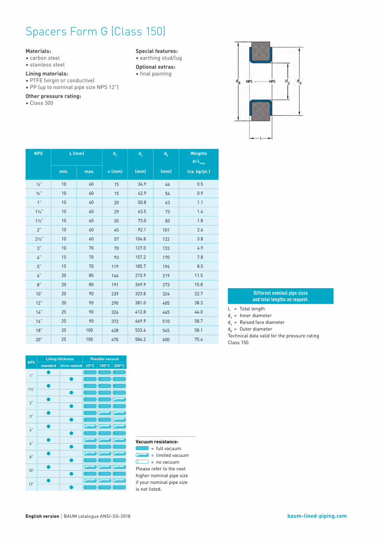
Spacers Form G (Class 150)For total lengths from 10 – 100 mm we reinforce the Spacers Form G with a resilient metal core.
baum-lined-piping.comEnglish version BAUM catalogue ANSI-SG-2018
Spacers Form G (Class 150)Materials:• carbon steel• stainless steelLining materials:• PTFE (virgin or conductive)• PP (up to nominal pipe size NPS 12”)Other pressure rating:• Class 300
Special features: • earthing stud/lugOptional extras: • final painting
L = Total lengthd2 = Inner diameterd4 = Raised face diameterd8 = Outer diameterTechnical data valid for the pressure rating Class 150.
NPSLining thickness Possible vacuum
standard thick-walled 23° C 150° C 200° C
1“
1½“
2“
3“
4“
6“
8“
10“
12“
Different nominal pipe sizesand total lengths on request.
Vacuum resistance: = full vacuum = limited vacuum = no vacuum
Please refer to the next higher nominal pipe size if your nominal pipe size is not listed.
NPS L (mm) d2
≈ (mm)
d4
(mm)
d8
(mm)
Weights at Lmax
(ca. kg/pc.)min. max.
½“ 10 60 15 34.9 44 0.5
¾“ 10 60 15 42.9 54 0.9
1“ 10 60 20 50.8 63 1.1
1¼“ 10 60 29 63.5 73 1.4
1½“ 10 60 35 73.0 83 1.8
2“ 10 60 45 92.1 101 2.6
2½“ 10 60 57 104.8 122 3.8
3“ 10 70 70 127.0 133 4.9
4“ 15 70 93 157.2 170 7.8
5“ 15 70 119 185.7 194 8.5
6“ 20 80 144 215.9 219 11.5
8“ 20 80 191 269.9 273 15.8
10“ 20 90 239 323.8 324 22.7
12“ 20 90 290 381.0 405 38.3
14“ 25 90 326 412.8 445 44.0
16“ 25 90 372 469.9 510 58.7
18“ 25 100 428 533.4 545 58.1
20“ 25 100 470 584.2 600 75.4

Spacers Form H (Class 150)Spacers Form H with a total length up to 250 mm consist of a pressure-resistant, but lightweight metal core with interior lining.

baum-lined-piping.comEnglish version BAUM catalogue ANSI-SH-2018
Spacers Form H (Class 150)Materials:• carbon steel• stainless steelLining materials:• PTFE (virgin or conductive)• PP (up to nominal pipe size NPS 12“)Other pressure rating:• Class 300
Special features: • earthing stud/lug• vent hole extensionOptional extras: • final painting• non-destructive testing
L = Total lengthd1 = Outer diameter of the steel piped4 = Raised face diameterd8 = Outer diameterTechnical data valid for the pressure rating Class 150.
NPSLining thickness Possible vacuum
standard thick-walled 23° C 150° C 200° C
1“
1½“
2“
3“
4“
6“
8“
10“
12“
Different nominal pipe sizesand total lengths on request.
Vacuum resistance: = full vacuum = limited vacuum = no vacuum
Please refer to the next higher nominal pipe size if your nominal pipe size is not listed.
NPS L (mm) d1
(mm)
d4
(mm)
d8
(mm)
Weights at Lmax
(ca. kg/pc.)min. max.
½“ 60 100 26.7 34.9 39.0 0.3
¾“ 60 100 26.7 42.9 47.0 0.3
1“ 60 100 33.4 50.8 54.0 0.4
1¼“ 60 100 42.2 63.5 67.0 0.6
1½“ 60 100 48.3 73.0 77.0 0.7
2“ 60 100 60.3 92.1 97.0 1.0
2½“ 60 100 73.0 104.8 108.0 1.4
3“ 70 125 88.9 127.0 131.0 2.3
4“ 70 125 114.3 157.2 161.0 3.2
5“ 70 150 141.3 185.7 190.0 5.2
6“ 80 150 168.3 215.9 219.0 6.6
8“ 80 200 219.1 269.9 270.0 12.4
10“ 80 200 273.0 323.8 324.0 17.0
12“ 80 200 323.8 381.0 381.0 21.7
14“ 80 250 355.6 412.8 413.0 31.4
16“ 90 250 406.4 469.9 470.0 37.6
18“ 100 250 457.0 533.4 533.4 44.8
20“ 100 250 508.0 584.2 586.0 49.2

Inclined Spacers (Class 150)Flexible in every situation! The Inclined Spacers can be delivered in any angle, tapered on one side only or on both sides.

baum-lined-piping.comEnglish version BAUM catalogue ANSI-AS-2018
Inclined Spacers (Class 150)Material:• PTFE (virgin or conductive)Other pressure rating:• Class 300The standard angle for Inclined Spacer is 3°,other angles on request.
L = Total lengthd2 = Inner diameterd8 = Outer diameterTechnical data valid for the pressure rating Class 150.
NPSLining thickness Possible vacuum
standard thick-walled 23° C 150° C 200° C
1“
1½“
2“
3“
4“
6“
8“
Different nominal pipe sizes and total lengths on request.
Vacuum resistance: = full vacuum = limited vacuum = no vacuum
Please refer to the next higher nominal pipe size if your nominal pipe size is not listed.
NPS L
(mm)
d2
≈ (mm)
d8
(mm)
Weights
(ca. kg/pc.)
1“ 15 20 63 0.1
1¼“ 15 29 73 0.1
1½“ 15 35 83 0.1
2“ 20 45 101 0.3
2½“ 20 57 122 0.4
3“ 20 70 133 0.4
4“ 25 93 170 0.9
5“ 25 119 194 1.0
6“ 35 144 219 1.6
8“ 35 191 273 2.2

Flanged Elbows

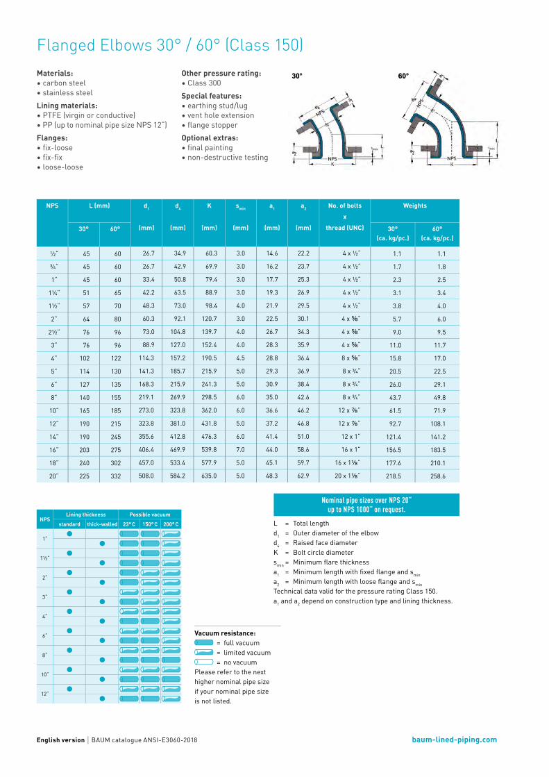
Flanged Elbows 30° / 60° (Class 150)The BAUM manufacturing technology with paste-extruded PTFE liner assures an optimum flow and an exact fitting of the liner in the elbow segment.
baum-lined-piping.comEnglish version BAUM catalogue ANSI-E3060-2018
Flanged Elbows 30° / 60° (Class 150)Materials:• carbon steel• stainless steelLining materials:• PTFE (virgin or conductive)• PP (up to nominal pipe size NPS 12“)Flanges:• fix-loose• fix-fix• loose-loose
Other pressure rating:• Class 300Special features: • earthing stud/lug• vent hole extension• flange stopper Optional extras: • final painting• non-destructive testing
NPSLining thickness Possible vacuum
standard thick-walled 23° C 150° C 200° C
1“
1½“
2“
3“
4“
6“
8“
10“
12“
L = Total lengthd1 = Outer diameter of the elbowd4 = Raised face diameterK = Bolt circle diametersmin = Minimum flare thicknessa1 = Minimum length with fixed flange and smin
a2 = Minimum length with loose flange and smin
Technical data valid for the pressure rating Class 150.a1 and a2 depend on construction type and lining thickness.
Nominal pipe sizes over NPS 20“ up to NPS 1000“ on request.
Vacuum resistance: = full vacuum = limited vacuum = no vacuum
Please refer to the next higher nominal pipe size if your nominal pipe size is not listed.
NPS L (mm) d1
(mm)
d4
(mm)
K
(mm)
smin
(mm)
a1
(mm)
a2
(mm)
No. of boltsx
thread (UNC)
Weights
30° 60° 30°(ca. kg/pc.)
60° (ca. kg/pc.)
½“ 45 60 26.7 34.9 60.3 3.0 14.6 22.2 4 x ½“ 1.1 1.1
¾“ 45 60 26.7 42.9 69.9 3.0 16.2 23.7 4 x ½“ 1.7 1.8
1“ 45 60 33.4 50.8 79.4 3.0 17.7 25.3 4 x ½“ 2.3 2.5
1¼“ 51 65 42.2 63.5 88.9 3.0 19.3 26.9 4 x ½“ 3.1 3.4
1½“ 57 70 48.3 73.0 98.4 4.0 21.9 29.5 4 x ½“ 3.8 4.0
2“ 64 80 60.3 92.1 120.7 3.0 22.5 30.1 4 x ⅝“ 5.7 6.0
2½“ 76 96 73.0 104.8 139.7 4.0 26.7 34.3 4 x ⅝“ 9.0 9.5
3“ 76 96 88.9 127.0 152.4 4.0 28.3 35.9 4 x ⅝“ 11.0 11.7
4“ 102 122 114.3 157.2 190.5 4.5 28.8 36.4 8 x ⅝“ 15.8 17.0
5“ 114 130 141.3 185.7 215.9 5.0 29.3 36.9 8 x ¾“ 20.5 22.5
6“ 127 135 168.3 215.9 241.3 5.0 30.9 38.4 8 x ¾“ 26.0 29.1
8“ 140 155 219.1 269.9 298.5 6.0 35.0 42.6 8 x ¾“ 43.7 49.8
10“ 165 185 273.0 323.8 362.0 6.0 36.6 46.2 12 x ⅞“ 61.5 71.9
12“ 190 215 323.8 381.0 431.8 5.0 37.2 46.8 12 x ⅞“ 92.7 108.1
14“ 190 245 355.6 412.8 476.3 6.0 41.4 51.0 12 x 1“ 121.4 141.2
16“ 203 275 406.4 469.9 539.8 7.0 44.0 58.6 16 x 1“ 156.5 183.5
18“ 240 302 457.0 533.4 577.9 5.0 45.1 59.7 16 x 1⅛“ 177.6 210.1
20“ 225 332 508.0 584.2 635.0 5.0 48.3 62.9 20 x 1⅛“ 218.5 258.6

Flanged Elbows 45° / 90° (Class 150)The BAUM manufacturing technology with paste-extruded PTFE liner assures an optimum flow and an exact fitting of the liner in the elbow segment.

baum-lined-piping.comEnglish version BAUM catalogue ANSI-E4590-2018
Flanged Elbows 45° / 90° (Class 150)
NPSLining thickness Possible vacuum
standard thick-walled 23° C 150° C 200° C
1“
1½“
2“
3“
4“
6“
8“
10“
12“
Types of Flanged Elbows 90°:• from nominal pipe size NPS 12“ as
two-part component• from nominal pipe size NPS 20“ as
three-part component
Materials:• carbon steel• stainless steelLining materials:• PTFE (virgin or conductive)• PP (up to nominal pipe size NPS 12“)Flanges:• fix-loose• fix-fix• loose-loose
Other pressure rating:• Class 300Special features: • earthing stud/lug• vent hole extension• flange stopper Optional extras: • final painting• non-destructive testing
Vacuum resistance: = full vacuum = limited vacuum = no vacuum
Please refer to the next higher nominal pipe size if your nominal pipe size is not listed.
L = Total lengthd1 = Outer diameter of the elbowd4 = Raised face diameterK = Bolt circle diametersmin = Minimum flare thicknessa1 = Minimum length with fixed flange and smin
a2 = Minimum length with loose flange and smin
Technical data valid for the pressure rating Class 150. a1 and a2 depend on construction type and lining thickness.
Nominal pipe sizes over NPS 20“up to NPS 1000“ on request.
NPS L (mm) d1
(mm)
d4
(mm)
K
(mm)
smin
(mm)
a1
(mm)
a2
(mm)
No. of bolts
x
thread (UNC)
Weights
45° 90° 45° 90° SR
SR LR (ca. kg/pc.) (ca. kg/pc.)
½“ 44 65 26.7 34.9 60.3 3.0 14.6 22.2 4 x ½“ 1.1 1.1
¾“ 44 75 26.7 42.9 69.9 3.0 16.2 23.7 4 x ½“ 1.7 1.8
1“ 44 89 127 33.4 50.8 79.4 3.0 17.7 25.3 4 x ½“ 2.4 2.6
1¼“ 51 95 140 42.2 63.5 88.9 3.0 19.3 26.9 4 x ½“ 3.2 3.5
1½“ 57 102 152 48.3 73.0 98.4 4.0 21.9 29.5 4 x ½“ 3.9 4.0
2“ 64 114 165 60.3 92.1 120.7 3.0 22.5 30.1 4 x ⅝“ 5.8 6.2
2½“ 76 127 178 73.0 104.8 139.7 4.0 26.7 34.3 4 x ⅝“ 9.3 10.0
3“ 76 140 197 88.9 127.0 152.4 4.0 28.3 35.9 4 x ⅝“ 11.4 12.3
4“ 102 165 229 114.3 157.2 190.5 4.5 28.8 36.4 8 x ⅝“ 16.4 18.1
5“ 114 190 260 141.3 185.7 215.9 5.0 29.3 36.9 8 x ¾“ 21.5 24.3
6“ 127 203 292 168.3 215.9 241.3 5.0 30.9 38.4 8 x ¾“ 27.5 31.7
8“ 140 229 356 219.1 269.9 298.5 6.0 35.0 42.6 8 x ¾“ 46.7 55.0
10“ 165 279 419 273.0 323.8 362.0 6.0 36.6 46.2 12 x ⅞“ 66.7 80.7
12“ 190 305 483 323.8 381.0 431.8 5.0 37.2 46.8 12 x ⅞“ 100.4 150.9
14“ 190 356 546 355.6 412.8 476.3 6.0 41.4 51.0 12 x 1“ 131.3 202.4
16“ 203 381 610 406.4 469.9 539.8 7.0 44.0 58.6 16 x 1“ 170.0 267.5
18“ 216 419 673 457.0 533.4 577.9 5.0 45.1 59.7 16 x 1⅛“ 193.8 312.5
20“ 241 457 737 508.0 584.2 635.0 5.0 48.3 62.9 20 x 1⅛“ 238.6 469.0
Flanged Tees

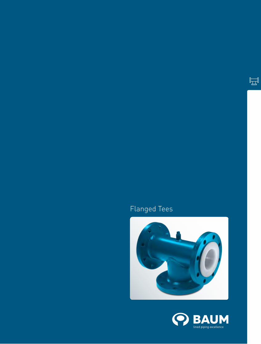
Flanged Tees (Class 150)The one-piece design with PFA or PP lining assures a perfect flow in the base body and at the outlet. The manufacturing of our one-piece Flanged Tees is done by injection moulding. For Flanged Tees with nominal pipe
sizes larger than NPS1 4“, we rely on our approved paste liner. Both manufacturing technologies assure a special smooth and easy-to-clean surface.
baum-lined-piping.comEnglish version BAUM catalogue ANSI-T-2018
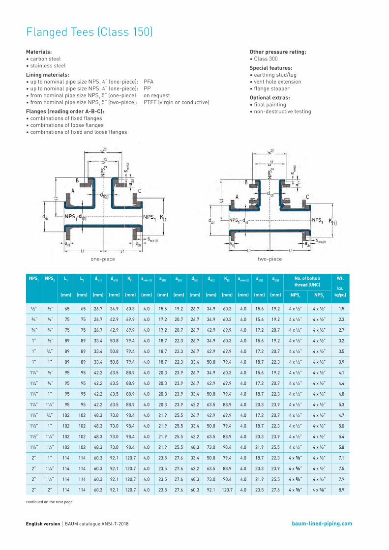
Flanged Tees (Class 150)Materials:• carbon steel• stainless steelLining materials:• up to nominal pipe size NPS1 4“ (one-piece): PFA• up to nominal pipe size NPS1 4“ (one-piece): PP• from nominal pipe size NPS1 5“ (one-piece): on request• from nominal pipe size NPS1 5“ (two-piece): PTFE (virgin or conductive)Flanges (reading order A-B-C):• combinations of fixed flanges • combinations of loose flanges• combinations of fixed and loose flanges
continued on the next page
Other pressure rating:• Class 300Special features: • earthing stud/lug• vent hole extension• flange stopper Optional extras: • final painting• non-destructive testing
one-piece two-piece
NPS1 NPS2 L1
(mm)
L2
(mm)
d1(1)
(mm)
d4(1)
(mm)
K(1)
(mm)
smin (1)
(mm)
a1(1)
(mm)
a2(1)
(mm)
d1(2)
(mm)
d4(2)
(mm)
K(2)
(mm)
smin (2)
(mm)
a1(2)
(mm)
a2(2)
(mm)
No. of bolts xthread (UNC)
Wt.
(ca. kg/pc.)NPS1 NPS2
½“ ½“ 65 65 26.7 34.9 60.3 4.0 15.6 19.2 26.7 34.9 60.3 4.0 15.6 19.2 4 x ½“ 4 x ½“ 1.5
¾“ ½“ 75 75 26.7 42.9 69.9 4.0 17.2 20.7 26.7 34.9 60.3 4.0 15.6 19.2 4 x ½“ 4 x ½“ 2.3
¾“ ¾“ 75 75 26.7 42.9 69.9 4.0 17.2 20.7 26.7 42.9 69.9 4.0 17.2 20.7 4 x ½“ 4 x ½“ 2.7
1“ ½“ 89 89 33.4 50.8 79.4 4.0 18.7 22.3 26.7 34.9 60.3 4.0 15.6 19.2 4 x ½“ 4 x ½“ 3.2
1“ ¾“ 89 89 33.4 50.8 79.4 4.0 18.7 22.3 26.7 42.9 69.9 4.0 17.2 20.7 4 x ½“ 4 x ½“ 3.5
1“ 1“ 89 89 33.4 50.8 79.4 4.0 18.7 22.3 33.4 50.8 79.4 4.0 18.7 22.3 4 x ½“ 4 x ½“ 3.9
1¼“ ½“ 95 95 42.2 63.5 88.9 4.0 20.3 23.9 26.7 34.9 60.3 4.0 15.6 19.2 4 x ½“ 4 x ½“ 4.1
1¼“ ¾“ 95 95 42.2 63.5 88.9 4.0 20.3 23.9 26.7 42.9 69.9 4.0 17.2 20.7 4 x ½“ 4 x ½“ 4.4
1¼“ 1“ 95 95 42.2 63.5 88.9 4.0 20.3 23.9 33.4 50.8 79.4 4.0 18.7 22.3 4 x ½“ 4 x ½“ 4.8
1¼“ 1¼“ 95 95 42.2 63.5 88.9 4.0 20.3 23.9 42.2 63.5 88.9 4.0 20.3 23.9 4 x ½“ 4 x ½“ 5.3
1½“ ¾“ 102 102 48.3 73.0 98.4 4.0 21.9 25.5 26.7 42.9 69.9 4.0 17.2 20.7 4 x ½“ 4 x ½“ 4.7
1½“ 1“ 102 102 48.3 73.0 98.4 4.0 21.9 25.5 33.4 50.8 79.4 4.0 18.7 22.3 4 x ½“ 4 x ½“ 5.0
1½“ 1¼“ 102 102 48.3 73.0 98.4 4.0 21.9 25.5 42.2 63.5 88.9 4.0 20.3 23.9 4 x ½“ 4 x ½“ 5.4
1½“ 1½“ 102 102 48.3 73.0 98.4 4.0 21.9 25.5 48.3 73.0 98.4 4.0 21.9 25.5 4 x ½“ 4 x ½“ 5.8
2“ 1“ 114 114 60.3 92.1 120.7 4.0 23.5 27.6 33.4 50.8 79.4 4.0 18.7 22.3 4 x ⅝“ 4 x ½“ 7.1
2“ 1¼“ 114 114 60.3 92.1 120.7 4.0 23.5 27.6 42.2 63.5 88.9 4.0 20.3 23.9 4 x ⅝“ 4 x ½“ 7.5
2“ 1½“ 114 114 60.3 92.1 120.7 4.0 23.5 27.6 48.3 73.0 98.4 4.0 21.9 25.5 4 x ⅝“ 4 x ½“ 7.9
2“ 2“ 114 114 60.3 92.1 120.7 4.0 23.5 27.6 60.3 92.1 120.7 4.0 23.5 27.6 4 x ⅝“ 4 x ⅝“ 8.9
baum-lined-piping.comEnglish version BAUM catalogue ANSI-T-2018
Flanged Tees (Class 150)
continued on the next page
NPS1 NPS2 L1
(mm)
L2
(mm)
d1(1)
(mm)
d4(1)
(mm)
K(1)
(mm)
smin (1)
(mm)
a1(1)
(mm)
a2(1)
(mm)
d1(2)
(mm)
d4(2)
(mm)
K(2)
(mm)
smin (2)
(mm)
a1(2)
(mm)
a2(2)
(mm)
No. of bolts xthread (UNC)
Wt.
(ca. kg/pc.)NPS1 NPS2
2½“ 1“ 127 127 73.0 104.8 139.7 4.0 26.7 31.5 33.4 50.8 79.4 4.0 18.7 22.3 4 x ⅝“ 4 x ½“ 10.7
2½“ 1¼“ 127 127 73.0 104.8 139.7 4.0 26.7 31.5 42.2 63.5 88.9 4.0 20.3 23.9 4 x ⅝“ 4 x ½“ 11.2
2½“ 1½“ 127 127 73.0 104.8 139.7 4.0 26.7 31.5 48.3 73.0 98.4 4.0 21.9 25.5 4 x ⅝“ 4 x ½“ 11.6
2½“ 2“ 127 127 73.0 104.8 139.7 4.0 26.7 31.5 60.3 92.1 120.7 4.0 23.5 27.6 4 x ⅝“ 4 x ⅝“ 12.6
2½“ 2½“ 127 127 73.0 104.8 139.7 4.0 26.7 31.5 73.0 104.8 139.7 4.0 26.7 31.5 4 x ⅝“ 4 x ⅝“ 14.3
3“ 1“ 140 140 88.9 127.0 152.4 4.0 28.3 33.4 33.4 50.8 79.4 4.0 18.7 22.3 4 x ⅝“ 4 x ½“ 13.2
3“ 1½“ 140 140 88.9 127.0 152.4 4.0 28.3 33.4 48.3 73.0 98.4 4.0 21.9 25.5 4 x ⅝“ 4 x ½“ 14.1
3“ 2“ 140 140 88.9 127.0 152.4 4.0 28.3 33.4 60.3 92.1 120.7 4.0 23.5 27.6 4 x ⅝“ 4 x ⅝“ 15.1
3“ 2½“ 140 140 88.9 127.0 152.4 4.0 28.3 33.4 73.0 104.8 139.7 4.0 26.7 31.5 4 x ⅝“ 4 x ⅝“ 16.9
3“ 3“ 140 140 88.9 127.0 152.4 4.0 28.3 33.4 88.9 127.0 152.4 4.0 28.3 33.4 4 x ⅝“ 4 x ⅝“ 18.0
4“ 1“ 165 165 114.3 157.2 190.5 4.0 28.3 33.9 33.4 50.8 79.4 4.0 18.7 22.3 8 x ⅝“ 4 x ½“ 18.8
4“ 2“ 165 165 114.3 157.2 190.5 4.0 28.3 33.9 60.3 92.1 120.7 4.0 23.5 27.6 8 x ⅝“ 4 x ⅝“ 20.8
4“ 2½“ 165 165 114.3 157.2 190.5 4.0 28.3 33.9 73.0 104.8 139.7 4.0 26.7 31.5 8 x ⅝“ 4 x ⅝“ 22.6
4“ 3“ 165 165 114.3 157.2 190.5 4.0 28.3 33.9 88.9 127.0 152.4 4.0 28.3 33.4 8 x ⅝“ 4 x ⅝“ 23.8
4“ 4“ 165 165 114.3 157.2 190.5 4.0 28.3 33.9 114.3 157.2 190.5 4.0 28.3 33.9 8 x ⅝“ 8 x ⅝“ 26.3
5“ 2½“ 190 190 141.3 185.7 215.9 5.0 29.3 35.5 73.0 104.8 139.7 3.0 25.7 30.5 8 x ¾“ 4 x ⅝“ 43.2
5“ 3“ 190 190 141.3 185.7 215.9 5.0 29.3 35.5 88.9 127.0 152.4 3.0 27.3 32.4 8 x ¾“ 4 x ⅝“ 46.3
5“ 4“ 190 190 141.3 185.7 215.9 5.0 29.3 35.5 114.3 157.2 190.5 3.0 27.3 32.9 8 x ¾“ 8 x ⅝“ 52.1
5“ 5“ 190 190 141.3 185.7 215.9 5.0 29.3 35.5 141.3 185.7 215.9 4.0 28.3 34.5 8 x ¾“ 8 x ¾“ 58.6
6“ 3“ 203 203 168.3 215.9 241.3 7.0 32.9 39.5 88.9 127.0 152.4 3.0 27.3 32.4 8 x ¾“ 4 x ⅝“ 53.1
6“ 4“ 203 203 168.3 215.9 241.3 7.0 32.9 39.5 114.3 157.2 190.5 3.0 27.3 32.9 8 x ¾“ 8 x ⅝“ 59.0
6“ 5“ 203 203 168.3 215.9 241.3 7.0 32.9 39.5 141.3 185.7 215.9 4.0 28.3 34.5 8 x ¾“ 8 x ¾“ 65.6
6“ 6“ 203 203 168.3 215.9 241.3 7.0 32.9 39.5 168.3 215.9 241.3 4.5 30.4 37.0 8 x ¾“ 8 x ¾“ 77.3
8“ 4“ 229 229 219.1 269.9 298.5 6.0 35.0 42.8 114.3 157.2 190.5 3.0 27.3 32.9 8 x ¾“ 8 x ⅝“ 79.2
8“ 5“ 229 229 219.1 269.9 298.5 6.0 35.0 42.8 141.3 185.7 215.9 4.0 28.3 34.5 8 x ¾“ 8 x ¾“ 86.0
8“ 6“ 229 229 219.1 269.9 298.5 6.0 35.0 42.8 168.3 215.9 241.3 4.5 30.4 37.0 8 x ¾“ 8 x ¾“ 97.9
8“ 8“ 229 229 219.1 269.9 298.5 6.0 35.0 42.8 219.1 269.9 298.5 5.0 34.0 41.8 8 x ¾“ 8 x ¾“ 115.4
10“ 5“ 279 279 273.0 323.8 362.0 7.5 38.1 47.0 141.3 185.7 215.9 4.0 28.3 34.5 12 x ⅞“ 8 x ¾“ 112.4
10“ 6“ 279 279 273.0 323.8 362.0 7.5 38.1 47.0 168.3 215.9 241.3 4.5 30.4 37.0 12 x ⅞“ 8 x ¾“ 124.7
10“ 8“ 279 279 273.0 323.8 362.0 7.5 38.1 47.0 219.1 269.9 298.5 5.0 34.0 41.8 12 x ⅞“ 8 x ¾“ 143.0
10“ 10“ 279 279 273.0 323.8 362.0 7.5 38.1 47.0 273.0 323.8 362.0 7.5 38.1 47.0 12 x ⅞“ 12 x ⅞“ 165.2
12“ 6“ 305 305 323.8 381.0 431.8 7.5 39.7 49.6 168.3 215.9 241.3 4.5 30.4 37.0 12 x ⅞“ 8 x ¾“ 159.5
12“ 8“ 305 305 323.8 381.0 431.8 7.5 39.7 49.6 219.1 269.9 298.5 5.0 34.0 41.8 12 x ⅞“ 8 x ¾“ 178.3
12“ 10“ 305 305 323.8 381.0 431.8 7.5 39.7 49.6 273.0 323.8 362.0 7.5 38.1 47.0 12 x ⅞“ 12 x ⅞“ 201.0
12“ 12“ 305 305 323.8 381.0 431.8 7.5 39.7 49.6 323.8 381.0 431.8 5.0 37.2 47.1 12 x ⅞“ 12 x ⅞“ 223.7
14“ 8“ 356 356 355.6 412.8 476.3 10.0 45.4 60.0 219.1 269.9 298.5 5.0 34.0 41.8 12 x 1“ 8 x ¾“ 215.3
14“ 10“ 356 356 355.6 412.8 476.3 10.0 45.4 60.0 273.0 323.8 362.0 7.5 38.1 47.0 12 x 1“ 12 x ⅞“ 239.0
14“ 12“ 356 356 355.6 412.8 476.3 10.0 45.4 60.0 323.8 381.0 431.8 5.0 37.2 47.1 12 x 1“ 12 x ⅞“ 262.5
14“ 14“ 356 356 355.6 412.8 476.3 10.0 45.4 60.0 355.6 412.8 476.3 5.0 40.4 55.0 12 x 1“ 12 x 1“ 304.7

baum-lined-piping.comEnglish version BAUM catalogue ANSI-T-2018
Flanged Tees (Class 150)
L = Total lengthd1 = Outer diameter of the piped4 = Raised face diameterK = Bolt circle diametersmin = Minimum flare thicknessa1 = Minimum length with fixed flange and smin
a2 = Minimum length with loose flange and smin
Technical data valid for the pressure rating Class 150. a1 and a2 depend on construction type and lining thickness.
NPS1
Lining thickness Possible vacuum
standard thick-walled 23° C 150° C 200° C
1“
1½“
2“
3“
4“
6“
8“
10“
12“
Different nominal pipe sizes and total lengths on request.
Vacuum resistance: = full vacuum = limited vacuum = no vacuum
Please refer to the next higher nominal pipe size if your nominal pipe size is not listed.
NPS1 NPS2 L1
(mm)
L2
(mm)
d1(1)
(mm)
d4(1)
(mm)
K(1)
(mm)
smin (1)
(mm)
a1(1)
(mm)
a2(1)
(mm)
d1(2)
(mm)
d4(2)
(mm)
K(2)
(mm)
smin (2)
(mm)
a1(2)
(mm)
a2(2)
(mm)
No. of bolts xthread (UNC)
Wt.
(ca. kg/pc.)NPS1 NPS2
16“ 10“ 381 381 406.4 469.9 539.8 7.0 44.0 58.6 273.0 323.8 362.0 7.5 38.1 47.0 16 x 1“ 12 x ⅞“ 283.3
16“ 12“ 381 381 406.4 469.9 539.8 7.0 44.0 58.6 323.8 381.0 431.8 5.0 37.2 47.1 16 x 1“ 12 x ⅞“ 307.2
16“ 14“ 381 381 406.4 469.9 539.8 7.0 44.0 58.6 355.6 412.8 476.3 5.0 40.4 55.0 16 x 1“ 12 x 1“ 349.6
16“ 16“ 381 381 406.4 469.9 539.8 7.0 44.0 58.6 406.4 469.9 539.8 5.0 42.0 56.6 16 x 1“ 16 x 1“ 402.5
18“ 12“ 419 419 457.0 533.4 577.9 8.0 48.1 62.7 323.8 381.0 431.8 5.0 37.2 47.1 16 x 1⅛“ 12 x ⅞“ 336.3
18“ 14“ 419 419 457.0 533.4 577.9 8.0 48.1 62.7 355.6 412.8 476.3 5.0 40.4 55.0 16 x 1⅛“ 12 x 1“ 379.0
18“ 16“ 419 419 457.0 533.4 577.9 8.0 48.1 62.7 406.4 469.9 539.8 5.0 42.0 56.6 16 x 1⅛“ 16 x 1“ 432.7
18“ 18“ 419 419 457.0 533.4 577.9 8.0 48.1 62.7 457.0 533.4 577.9 5.0 45.1 59.7 16 x 1⅛“ 16 x 1⅛“ 469.9
20“ 12“ 457 457 508.0 584.2 635.0 8.0 51.3 65.9 323.8 381.0 431.8 5.0 37.2 47.1 20 x 1⅛“ 12 x ⅞“ 389.3
20“ 14“ 457 457 508.0 584.2 635.0 8.0 51.3 65.9 355.6 412.8 476.3 5.0 40.4 55.0 20 x 1⅛“ 12 x 1“ 432.4
20“ 16“ 457 457 508.0 584.2 635.0 8.0 51.3 65.9 406.4 469.9 539.8 5.0 42.0 56.6 20 x 1⅛“ 16 x 1“ 486.8
20“ 18“ 457 457 508.0 584.2 635.0 8.0 51.3 65.9 457.0 533.4 577.9 5.0 45.1 59.7 20 x 1⅛“ 16 x 1⅛“ 524.3
20“ 20“ 457 457 508.0 584.2 635.0 8.0 51.3 65.9 508.0 584.2 635.0 5.0 48.3 62.9 20 x 1⅛“ 20 x 1⅛“ 571.1
Flanged Lateral Tees

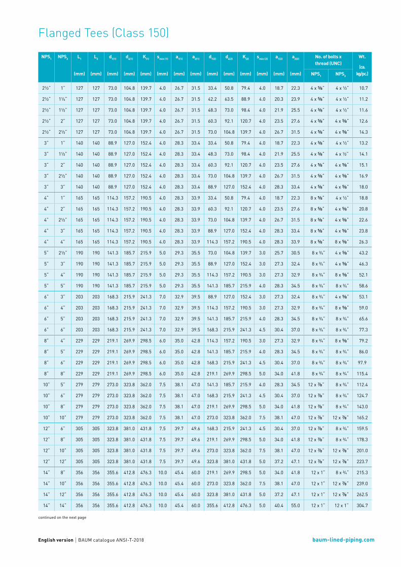
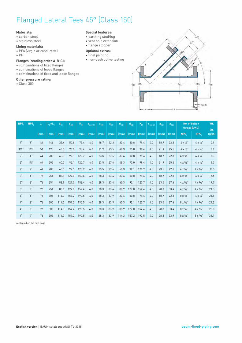
Flanged Lateral Tees 45° (Class 150)The one-piece design with PFA or PP lining offers a low-resistance flow through the entire component by a streamlined geometry.
baum-lined-piping.comEnglish version BAUM catalogue ANSI-TL-2018
Flanged Lateral Tees 45° (Class 150)Materials:• carbon steel• stainless steelLining materials:• PFA (virgin or conductive)• PPFlanges (reading order A-B-C):• combinations of fixed flanges • combinations of loose flanges• combinations of fixed and loose flanges Other pressure rating:• Class 300
continued on the next page
Special features: • earthing stud/lug• vent hole extension• flange stopperOptional extras: • final painting• non-destructive testing
NPS1 NPS2 L1
(mm)
L2 = L3
(mm)
d1(1)
(mm)
d4(1)
(mm)
K(1)
(mm)
smin (1)
(mm)
a1(1)
(mm)
a2(1)
(mm)
d1(2)
(mm)
d4(2)
(mm)
K(2)
(mm)
smin (2)
(mm)
a1(2)
(mm)
a2(2)
(mm)
No. of bolts xthread (UNC)
Wt.
(ca. kg/pc.)NPS1 NPS2
1“ 1“ 44 146 33.4 50.8 79.4 4.0 18.7 22.3 33.4 50.8 79.4 4.0 18.7 22.3 4 x ½“ 4 x ½“ 3.9
1½“ 1½“ 51 178 48.3 73.0 98.4 4.0 21.9 25.5 48.3 73.0 98.4 4.0 21.9 25.5 4 x ½“ 4 x ½“ 6.9
2“ 1“ 64 203 60.3 92.1 120.7 4.0 23.5 27.6 33.4 50.8 79.4 4.0 18.7 22.3 4 x ⅝“ 4 x ½“ 8.3
2“ 1½“ 64 203 60.3 92.1 120.7 4.0 23.5 27.6 48.3 73.0 98.4 4.0 21.9 25.5 4 x ⅝“ 4 x ½“ 9.3
2“ 2“ 64 203 60.3 92.1 120.7 4.0 23.5 27.6 60.3 92.1 120.7 4.0 23.5 27.6 4 x ⅝“ 4 x ⅝“ 10.5
3“ 1“ 76 254 88.9 127.0 152.4 4.0 28.3 33.4 33.4 50.8 79.4 4.0 18.7 22.3 4 x ⅝“ 4 x ½“ 15.5
3“ 2“ 76 254 88.9 127.0 152.4 4.0 28.3 33.4 60.3 92.1 120.7 4.0 23.5 27.6 4 x ⅝“ 4 x ⅝“ 17.7
3“ 3“ 76 254 88.9 127.0 152.4 4.0 28.3 33.4 88.9 127.0 152.4 4.0 28.3 33.4 4 x ⅝“ 4 x ⅝“ 21.3
4“ 1“ 76 305 114.3 157.2 190.5 4.0 28.3 33.9 33.4 50.8 79.4 4.0 18.7 22.3 8 x ⅝“ 4 x ½“ 21.8
4“ 2“ 76 305 114.3 157.2 190.5 4.0 28.3 33.9 60.3 92.1 120.7 4.0 23.5 27.6 8 x ⅝“ 4 x ⅝“ 24.2
4“ 3“ 76 305 114.3 157.2 190.5 4.0 28.3 33.9 88.9 127.0 152.4 4.0 28.3 33.4 8 x ⅝“ 4 x ⅝“ 28.0
4“ 4“ 76 305 114.3 157.2 190.5 4.0 28.3 33.9 114.3 157.2 190.5 4.0 28.3 33.9 8 x ⅝“ 8 x ⅝“ 31.1

baum-lined-piping.comEnglish version BAUM catalogue ANSI-TL-2018
Flanged Lateral Tees 45° (Class 150)
NPS1
Lining thickness Possible vacuum
standard thick-walled 23° C 150° C 200° C
1“
1½“
2“
3“
4“
L = Total lengthd1 = Outer diameter of the piped4 = Raised face diameterK = Bolt circle diametersmin = Minimum flare thicknessa1 = Minimum length with fixed flange and smin
a2 = Minimum length with loose flangeand smin
Technical data valid for the pressure rating Class 150. a1 and a2 depend on construction type and lining thickness.
Different nominal pipe sizes and total lengths on request.
Vacuum resistance: = full vacuum = limited vacuum = no vacuum
Please refer to the next higher nominal pipe size if your nomi-nal pipe size is not listed.
NPS1 NPS2 Possible flanges
fix-fix-fix fix-fix-loose fix-loose-fix loose-fix-fix fix-loose-loose loose-loose-fix loose-fix-Los loose-loose-loose
1“ 1“ - - - - - -
1½“ 1½“ - -
2“ 1“
2“ 1½“ - -
2“ 2“ - - - - - -
3“ 1“
3“ 2“
3“ 3“ - - - - - -
4“ 1“
4“ 2“
4“ 3“ - -
4“ 4“ - - - - - -

Flanged Crosses

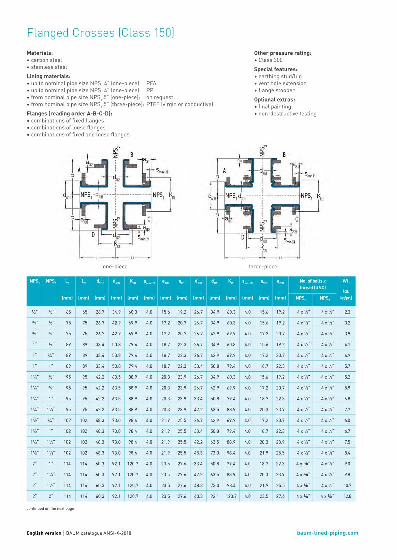
Flanged Crosses (Class 150)The one-piece design with PFA or PP lining assures a perfect flow in all four directions. The manufacturing of our one-piece Flanged Crosses is done by injection moulding. For Flanged Crosses with nominal pipe sizes
larger than NPS1 4“, we rely on our approved paste liner. Both manufacturing technologies assure a specially smooth and easy-to-clean surface.
baum-lined-piping.comEnglish version BAUM catalogue ANSI-X-2018
Flanged Crosses (Class 150)Materials:• carbon steel• stainless steelLining materials:• up to nominal pipe size NPS1 4“ (one-piece): PFA• up to nominal pipe size NPS1 4“ (one-piece): PP• from nominal pipe size NPS1 5“ (one-piece): on request• from nominal pipe size NPS1 5“ (three-piece): PTFE (virgin or conductive)Flanges (reading order A-B-C-D):• combinations of fixed flanges • combinations of loose flanges• combinations of fixed and loose flanges
continued on the next page
Other pressure rating:• Class 300Special features: • earthing stud/lug• vent hole extension• flange stopperOptional extras: • final painting• non-destructive testing
one-piece three-piece
NPS1 NPS2 L1
(mm)
L2
(mm)
d1(1)
(mm)
d4(1)
(mm)
K(1)
(mm)
smin (1)
(mm)
a1(1)
(mm)
a2(1)
(mm)
d1(2)
(mm)
d4(2)
(mm)
K(2)
(mm)
smin (2)
(mm)
a1(2)
(mm)
a2(2)
(mm)
No. of bolts xthread (UNC)
Wt.
(ca. kg/pc.)NPS1 NPS2
½“ ½“ 65 65 26.7 34.9 60.3 4.0 15.6 19.2 26.7 34.9 60.3 4.0 15.6 19.2 4 x ½“ 4 x ½“ 2.3
¾“ ½“ 75 75 26.7 42.9 69.9 4.0 17.2 20.7 26.7 34.9 60.3 4.0 15.6 19.2 4 x ½“ 4 x ½“ 3.2
¾“ ¾“ 75 75 26.7 42.9 69.9 4.0 17.2 20.7 26.7 42.9 69.9 4.0 17.2 20.7 4 x ½“ 4 x ½“ 3.9
1“ ½“ 89 89 33.4 50.8 79.4 4.0 18.7 22.3 26.7 34.9 60.3 4.0 15.6 19.2 4 x ½“ 4 x ½“ 4.1
1“ ¾“ 89 89 33.4 50.8 79.4 4.0 18.7 22.3 26.7 42.9 69.9 4.0 17.2 20.7 4 x ½“ 4 x ½“ 4.9
1“ 1“ 89 89 33.4 50.8 79.4 4.0 18.7 22.3 33.4 50.8 79.4 4.0 18.7 22.3 4 x ½“ 4 x ½“ 5.7
1¼“ ½“ 95 95 42.2 63.5 88.9 4.0 20.3 23.9 26.7 34.9 60.3 4.0 15.6 19.2 4 x ½“ 4 x ½“ 5.2
1¼“ ¾“ 95 95 42.2 63.5 88.9 4.0 20.3 23.9 26.7 42.9 69.9 4.0 17.2 20.7 4 x ½“ 4 x ½“ 5.9
1¼“ 1“ 95 95 42.2 63.5 88.9 4.0 20.3 23.9 33.4 50.8 79.4 4.0 18.7 22.3 4 x ½“ 4 x ½“ 6.8
1¼“ 1¼“ 95 95 42.2 63.5 88.9 4.0 20.3 23.9 42.2 63.5 88.9 4.0 20.3 23.9 4 x ½“ 4 x ½“ 7.7
1½“ ¾“ 102 102 48.3 73.0 98.4 4.0 21.9 25.5 26.7 42.9 69.9 4.0 17.2 20.7 4 x ½“ 4 x ½“ 6.0
1½“ 1“ 102 102 48.3 73.0 98.4 4.0 21.9 25.5 33.4 50.8 79.4 4.0 18.7 22.3 4 x ½“ 4 x ½“ 6.7
1½“ 1¼“ 102 102 48.3 73.0 98.4 4.0 21.9 25.5 42.2 63.5 88.9 4.0 20.3 23.9 4 x ½“ 4 x ½“ 7.5
1½“ 1½“ 102 102 48.3 73.0 98.4 4.0 21.9 25.5 48.3 73.0 98.4 4.0 21.9 25.5 4 x ½“ 4 x ½“ 8.4
2“ 1“ 114 114 60.3 92.1 120.7 4.0 23.5 27.6 33.4 50.8 79.4 4.0 18.7 22.3 4 x ⅝“ 4 x ½“ 9.0
2“ 1¼“ 114 114 60.3 92.1 120.7 4.0 23.5 27.6 42.2 63.5 88.9 4.0 20.3 23.9 4 x ⅝“ 4 x ½“ 9.8
2“ 1½“ 114 114 60.3 92.1 120.7 4.0 23.5 27.6 48.3 73.0 98.4 4.0 21.9 25.5 4 x ⅝“ 4 x ½“ 10.7
2“ 2“ 114 114 60.3 92.1 120.7 4.0 23.5 27.6 60.3 92.1 120.7 4.0 23.5 27.6 4 x ⅝“ 4 x ⅝“ 12.8

baum-lined-piping.comEnglish version BAUM catalogue ANSI-X-2018
Flanged Crosses (Class 150)
continued on the next page
NPS1 NPS2 L1
(mm)
L2
(mm)
d1(1)
(mm)
d4(1)
(mm)
K(1)
(mm)
smin (1)
(mm)
a1(1)
(mm)
a2(1)
(mm)
d1(2)
(mm)
d4(2)
(mm)
K(2)
(mm)
smin (2)
(mm)
a1(2)
(mm)
a2(2)
(mm)
No. of bolts xthread (UNC)
Wt.
(ca. kg/pc.)NPS1 NPS2
2½“ 1“ 127 127 73.0 104.8 139.7 4.0 26.7 31.5 33.4 50.8 79.4 4.0 18.7 22.3 4 x ⅝“ 4 x ½“ 12.9
2½“ 1¼“ 127 127 73.0 104.8 139.7 4.0 26.7 31.5 42.2 63.5 88.9 4.0 20.3 23.9 4 x ⅝“ 4 x ½“ 13.8
2½“ 1½“ 127 127 73.0 104.8 139.7 4.0 26.7 31.5 48.3 73.0 98.4 4.0 21.9 25.5 4 x ⅝“ 4 x ½“ 14.7
2½“ 2“ 127 127 73.0 104.8 139.7 4.0 26.7 31.5 60.3 92.1 120.7 4.0 23.5 27.6 4 x ⅝“ 4 x ⅝“ 16.9
2½“ 2½“ 127 127 73.0 104.8 139.7 4.0 26.7 31.5 73.0 104.8 139.7 4.0 26.7 31.5 4 x ⅝“ 4 x ⅝“ 20.6
3“ 1“ 140 140 88.9 127.0 152.4 4.0 28.3 33.4 33.4 50.8 79.4 4.0 18.7 22.3 4 x ⅝“ 4 x ½“ 15.6
3“ 1½“ 140 140 88.9 127.0 152.4 4.0 28.3 33.4 48.3 73.0 98.4 4.0 21.9 25.5 4 x ⅝“ 4 x ½“ 17.5
3“ 2“ 140 140 88.9 127.0 152.4 4.0 28.3 33.4 60.3 92.1 120.7 4.0 23.5 27.6 4 x ⅝“ 4 x ⅝“ 19.7
3“ 2½“ 140 140 88.9 127.0 152.4 4.0 28.3 33.4 73.0 104.8 139.7 4.0 26.7 31.5 4 x ⅝“ 4 x ⅝“ 23.4
3“ 3“ 140 140 88.9 127.0 152.4 4.0 28.3 33.4 88.9 127.0 152.4 4.0 28.3 33.4 4 x ⅝“ 4 x ⅝“ 25.8
4“ 1“ 165 165 114.3 157.2 190.5 4.0 28.3 33.9 33.4 50.8 79.4 4.0 18.7 22.3 8 x ⅝“ 4 x ½“ 21.7
4“ 2“ 165 165 114.3 157.2 190.5 4.0 28.3 33.9 60.3 92.1 120.7 4.0 23.5 27.6 8 x ⅝“ 4 x ⅝“ 25.9
4“ 2½“ 165 165 114.3 157.2 190.5 4.0 28.3 33.9 73.0 104.8 139.7 4.0 26.7 31.5 8 x ⅝“ 4 x ⅝“ 29.9
4“ 3“ 165 165 114.3 157.2 190.5 4.0 28.3 33.9 88.9 127.0 152.4 4.0 28.3 33.4 8 x ⅝“ 4 x ⅝“ 32.4
4“ 4“ 165 165 114.3 157.2 190.5 4.0 28.3 33.9 114.3 157.2 190.5 4.0 28.3 33.9 8 x ⅝“ 8 x ⅝“ 37.6
5“ 2½“ 190 190 141.3 185.7 215.9 5.0 29.3 35.5 73.0 104.8 139.7 3.0 25.7 30.5 8 x ¾“ 4 x ⅝“ 51.1
5“ 3“ 190 190 141.3 185.7 215.9 5.0 29.3 35.5 88.9 127.0 152.4 3.0 27.3 32.4 8 x ¾“ 4 x ⅝“ 55.5
5“ 4“ 190 190 141.3 185.7 215.9 5.0 29.3 35.5 114.3 157.2 190.5 3.0 27.3 32.9 8 x ¾“ 8 x ⅝“ 64.2
5“ 5“ 190 190 141.3 185.7 215.9 5.0 29.3 35.5 141.3 185.7 215.9 4.0 28.3 34.5 8 x ¾“ 8 x ¾“ 73.5
6“ 3“ 203 203 168.3 215.9 241.3 7.0 32.9 39.5 88.9 127.0 152.4 3.0 27.3 32.4 8 x ¾“ 4 x ⅝“ 63.0
6“ 4“ 203 203 168.3 215.9 241.3 7.0 32.9 39.5 114.3 157.2 190.5 3.0 27.3 32.9 8 x ¾“ 8 x ⅝“ 71.8
6“ 5“ 203 203 168.3 215.9 241.3 7.0 32.9 39.5 141.3 185.7 215.9 4.0 28.3 34.5 8 x ¾“ 8 x ¾“ 81.3
6“ 6“ 203 203 168.3 215.9 241.3 7.0 32.9 39.5 168.3 215.9 241.3 4.5 30.4 37.0 8 x ¾“ 8 x ¾“ 96.3
8“ 4“ 229 229 219.1 269.9 298.5 6.0 35.0 42.8 114.3 157.2 190.5 3.0 27.3 32.9 8 x ¾“ 8 x ⅝“ 94.0
8“ 5“ 229 229 219.1 269.9 298.5 6.0 35.0 42.8 141.3 185.7 215.9 4.0 28.3 34.5 8 x ¾“ 8 x ¾“ 103.9
8“ 6“ 229 229 219.1 269.9 298.5 6.0 35.0 42.8 168.3 215.9 241.3 4.5 30.4 37.0 8 x ¾“ 8 x ¾“ 119.4
8“ 8“ 229 229 219.1 269.9 298.5 6.0 35.0 42.8 219.1 269.9 298.5 5.0 34.0 41.8 8 x ¾“ 8 x ¾“ 147.2
10“ 5“ 279 279 273.0 323.8 362.0 7.5 38.1 47.0 141.3 185.7 215.9 4.0 28.3 34.5 12 x ⅞“ 8 x ¾“ 133.7
10“ 6“ 279 279 273.0 323.8 362.0 7.5 38.1 47.0 168.3 215.9 241.3 4.5 30.4 37.0 12 x ⅞“ 8 x ¾“ 150.0
10“ 8“ 279 279 273.0 323.8 362.0 7.5 38.1 47.0 219.1 269.9 298.5 5.0 34.0 41.8 12 x ⅞“ 8 x ¾“ 179.6
10“ 10“ 279 279 273.0 323.8 362.0 7.5 38.1 47.0 273.0 323.8 362.0 7.5 38.1 47.0 12 x ⅞“ 12 x ⅞“ 212.9
12“ 6“ 305 305 323.8 381.0 431.8 7.5 39.7 49.6 168.3 215.9 241.3 4.5 30.4 37.0 12 x ⅞“ 8 x ¾“ 188.2
12“ 8“ 305 305 323.8 381.0 431.8 7.5 39.7 49.6 219.1 269.9 298.5 5.0 34.0 41.8 12 x ⅞“ 8 x ¾“ 218.7
12“ 10“ 305 305 323.8 381.0 431.8 7.5 39.7 49.6 273.0 323.8 362.0 7.5 38.1 47.0 12 x ⅞“ 12 x ⅞“ 253.2
12“ 12“ 305 305 323.8 381.0 431.8 7.5 39.7 49.6 323.8 381.0 431.8 5.0 37.2 47.1 12 x ⅞“ 12 x ⅞“ 293.3
14“ 8“ 356 356 355.6 412.8 476.3 10.0 45.4 60.0 219.1 269.9 298.5 5.0 34.0 41.8 12 x 1“ 8 x ¾“ 261.4
14“ 10“ 356 356 355.6 412.8 476.3 10.0 45.4 60.0 273.0 323.8 362.0 7.5 38.1 47.0 12 x 1“ 12 x ⅞“ 298.1
14“ 12“ 356 356 355.6 412.8 476.3 10.0 45.4 60.0 323.8 381.0 431.8 5.0 37.2 47.1 12 x 1“ 12 x ⅞“ 339.9
14“ 14“ 356 356 355.6 412.8 476.3 10.0 45.4 60.0 355.6 412.8 476.3 5.0 40.4 55.0 12 x 1“ 12 x 1“ 397.2

baum-lined-piping.comEnglish version BAUM catalogue ANSI-X-2018
Flanged Crosses (Class 150)
NPS1
Lining thickness Possible vacuum
standard thick-walled 23° C 150° C 200° C
1“
1½“
2“
3“
4“
6“
8“
10“
12“
L = Total lengthd1 = Outer diameter of the piped4 = Raised face diameterK = Bolt circle diametersmin = Minimum flare thicknessa1 = Minimum length with fixed flange and smin
a2 = Minimum length with loose flange and smin
Technical data valid for the pressure rating Class 150.a1 and a2 depend on construction type and lining thickness.
Different nominal pipe sizes and total lengths on request.
Vacuum resistance: = full vacuum = limited vacuum = no vacuum
Please refer to the next higher nominal pipe size if your nominal pipe size is not listed.
NPS1 NPS2 L1
(mm)
L2
(mm)
d1(1)
(mm)
d4(1)
(mm)
K(1)
(mm)
smin (1)
(mm)
a1(1)
(mm)
a2(1)
(mm)
d1(2)
(mm)
d4(2)
(mm)
K(2)
(mm)
smin (2)
(mm)
a1(2)
(mm)
a2(2)
(mm)
No. of bolts xthread (UNC)
Wt.
(ca. kg/pc.)NPS1 NPS2
16“ 10“ 381 381 406.4 469.9 539.8 7.0 44.0 58.6 273.0 323.8 362.0 7.5 38.1 47.0 16 x 1“ 12 x ⅞“ 347.4
16“ 12“ 381 381 406.4 469.9 539.8 7.0 44.0 58.6 323.8 381.0 431.8 5.0 37.2 47.1 16 x 1“ 12 x ⅞“ 390.1
16“ 14“ 381 381 406.4 469.9 539.8 7.0 44.0 58.6 355.6 412.8 476.3 5.0 40.4 55.0 16 x 1“ 12 x 1“ 447.9
16“ 16“ 381 381 406.4 469.9 539.8 7.0 44.0 58.6 406.4 469.9 539.8 5.0 42.0 56.6 16 x 1“ 16 x 1“ 521.8
18“ 12“ 419 419 457.0 533.4 577.9 8.0 48.1 62.7 323.8 381.0 431.8 5.0 37.2 47.1 16 x 1⅛“ 12 x ⅞“ 424.8
18“ 14“ 419 419 457.0 533.4 577.9 8.0 48.1 62.7 355.6 412.8 476.3 5.0 40.4 55.0 16 x 1⅛“ 12 x 1“ 483.3
18“ 16“ 419 419 457.0 533.4 577.9 8.0 48.1 62.7 406.4 469.9 539.8 5.0 42.0 56.6 16 x 1⅛“ 16 x 1“ 558.8
18“ 18“ 419 419 457.0 533.4 577.9 8.0 48.1 62.7 457.0 533.4 577.9 5.0 45.1 59.7 16 x 1⅛“ 16 x 1⅛“ 605.2
20“ 12“ 457 457 508.0 584.2 635.0 8.0 51.3 65.9 323.8 381.0 431.8 5.0 37.2 47.1 20 x 1⅛“ 12 x ⅞“ 485.4
20“ 14“ 457 457 508.0 584.2 635.0 8.0 51.3 65.9 355.6 412.8 476.3 5.0 40.4 55.0 20 x 1⅛“ 12 x 1“ 544.6
20“ 16“ 457 457 508.0 584.2 635.0 8.0 51.3 65.9 406.4 469.9 539.8 5.0 42.0 56.6 20 x 1⅛“ 16 x 1“ 621.7
20“ 18“ 457 457 508.0 584.2 635.0 8.0 51.3 65.9 457.0 533.4 577.9 5.0 45.1 59.7 20 x 1⅛“ 16 x 1⅛“ 668.7
20“ 20“ 457 457 508.0 584.2 635.0 8.0 51.3 65.9 508.0 584.2 635.0 5.0 48.3 62.9 20 x 1⅛“ 20 x 1⅛“ 738.9
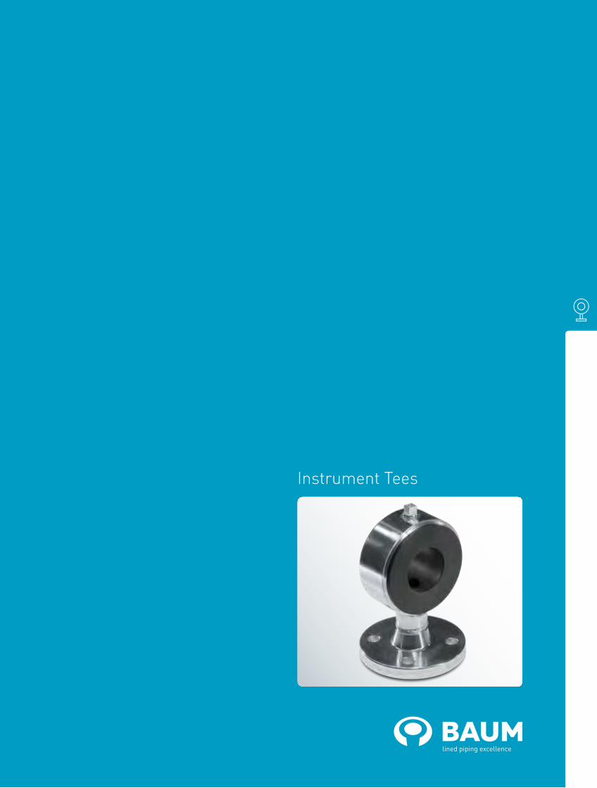
Instrument Tees

Instrument Tees (Class 150)Instrument Tees, also known as gauge connections, are the one-piece solution with PFA or PP lining for the connection to your measuring devices. In case of narrow space, also useable as short tee.

baum-lined-piping.comEnglish version BAUM catalogue ANSI-IT-2018
Instrument Tees (Class 150)Materials:• carbon steel• stainless steelLining materials:• PFA (virgin or conductive)• PPOther pressure rating:• Class 300
continued on the next page
Special features: • earthing stud/lug• vent hole extensionOptional extras: • final painting
NPS1 NPS2 L
(mm)
H
(mm)
d4(2)
(mm)
K(2)
(mm)
smin (2)
(mm)
a1(2)
(mm)
No. of bolts x
thread (UNC)
NPS2
Weights
(ca. kg/piece)
1“ ½“ 50 90 34.9 60.3 4.0 15.6 4 x ½“ 1.5
1“ ¾“ 50 90 42.9 69.9 4.0 17.2 4 x ½“ 1.8
1“ 1“ 50 90 50.8 79.4 4.0 18.7 4 x ½“ 2.1
1¼“ ½“ 50 100 34.9 60.3 4.0 15.6 4 x ½“ 1.4
1¼“ ¾“ 50 100 42.9 69.9 4.0 17.2 4 x ½“ 1.7
1¼“ 1“ 50 100 50.8 79.4 4.0 18.7 4 x ½“ 2.0
1½“ ½“ 50 110 34.9 60.3 4.0 15.6 4 x ½“ 2.1
1½“ ¾“ 50 110 42.9 69.9 4.0 17.2 4 x ½“ 2.4
1½“ 1“ 50 110 50.8 79.4 4.0 18.7 4 x ½“ 2.7
1½“ 1½“ 75 110 73.0 98.4 4.0 21.9 4 x ½“ 4.4
2“ ½“ 50 115 34.9 60.3 4.0 15.6 4 x ½“ 2.8
2“ ¾“ 50 115 42.9 69.9 4.0 17.2 4 x ½“ 3.1
2“ 1“ 50 115 50.8 79.4 4.0 18.7 4 x ½“ 3.4
2“ 1½“ 75 115 73.0 98.4 4.0 21.9 4 x ½“ 5.5
2“ 2“ 90 115 92.1 120.7 4.0 23.5 4 x ⅝“ 7.2
2½“ ½“ 50 125 34.9 60.3 4.0 15.6 4 x ½“ 2.9
2½“ ¾“ 50 125 42.9 69.9 4.0 17.2 4 x ½“ 3.2
2½“ 1“ 50 125 50.8 79.4 4.0 18.7 4 x ½“ 3.5
2½“ 1½“ 75 125 73.0 98.4 4.0 21.9 4 x ½“ 5.7
2½“ 2“ 90 125 92.1 120.7 4.0 23.5 4 x ⅝“ 7.4
3“ ½“ 50 135 34.9 60.3 4.0 15.6 4 x ½“ 4.0
3“ ¾“ 50 135 42.9 69.9 4.0 17.2 4 x ½“ 4.3
3“ 1“ 50 135 50.8 79.4 4.0 18.7 4 x ½“ 4.6
3“ 1½“ 75 135 73.0 98.4 4.0 21.9 4 x ½“ 7.4
3“ 2“ 90 135 92.1 120.7 4.0 23.5 4 x ⅝“ 9.6
4“ ½“ 50 150 34.9 60.3 4.0 15.6 4 x ½“ 5.0
4“ ¾“ 50 150 42.9 69.9 4.0 17.2 4 x ½“ 5.3
4“ 1“ 50 150 50.8 79.4 4.0 18.7 4 x ½“ 5.6
4“ 1½“ 75 150 73.0 98.4 4.0 21.9 4 x ½“ 9.0
4“ 2“ 90 150 92.1 120.7 4.0 23.5 4 x ⅝“ 13.7
5“ ½“ 50 160 34.9 60.3 4.0 15.6 4 x ½“ 6.5
5“ ¾“ 50 160 42.9 69.9 4.0 17.2 4 x ½“ 6.8
5“ 1“ 50 160 50.8 79.4 4.0 18.7 4 x ½“ 7.1
5“ 1½“ 75 160 73.0 98.4 4.0 21.9 4 x ½“ 11.4
5“ 2“ 90 160 92.1 120.7 4.0 23.5 4 x ⅝“ 14.4

baum-lined-piping.comEnglish version BAUM catalogue ANSI-IT-2018
Instrument Tees (Class 150)
NPS1
Lining thickness Possible vacuum
standard thick-walled 23° C 150° C 200° C
1“
1½“
2“
3“
4“
6“
8“
10“
12“
Vacuum resistance: = full vacuum = limited vacuum = no vacuum
Please refer to the next higher nominal pipe size if your nomi-nal pipe size is not listed.
L = Total lengthH = Overall heightd4 = Raised face diameterK = Bolt circle diametersmin = Minimum flare thicknessa1 = Minimum length with fixed flange and
smin
Technical data valid for the pressure rating Class 150. a1 depends on construction type and lining thickness.
Different nominal pipe sizes and total lengths on request.
NPS1 NPS2 L
(mm)
H
(mm)
d4(2)
(mm)
K(2)
(mm)
smin (2)
(mm)
a1(2)
(mm)
No. of bolts x
thread (UNC)
NPS2
Weights
(ca. kg/piece)
6“ ½“ 50 180 34.9 60.3 4.0 15.6 4 x ½“ 7.9
6“ ¾“ 50 180 42.9 69.9 4.0 17.2 4 x ½“ 8.2
6“ 1“ 50 180 50.8 79.4 4.0 18.7 4 x ½“ 8.5
6“ 1½“ 75 180 73.0 98.4 4.0 21.9 4 x ½“ 13.5
6“ 2“ 90 180 92.1 120.7 4.0 23.5 4 x ⅝“ 17.0
8“ ½“ 50 210 34.9 60.3 4.0 15.6 4 x ½“ 10.5
8“ ¾“ 50 210 42.9 69.9 4.0 17.2 4 x ½“ 10.8
8“ 1“ 50 210 50.8 79.4 4.0 18.7 4 x ½“ 11.2
8“ 1½“ 75 210 73.0 98.4 4.0 21.9 4 x ½“ 17.7
8“ 2“ 90 210 92.1 120.7 4.0 23.5 4 x ⅝“ 22.1
10“ 1“ 50 240 50.8 79.4 4.0 18.7 4 x ½“ 13.5
10“ 1½“ 75 240 73.0 98.4 4.0 21.9 4 x ½“ 21.4
10“ 2“ 90 240 92.1 120.7 4.0 23.5 4 x ⅝“ 26.6
12“ 1“ 50 340 50.8 79.4 4.0 18.7 4 x ½“ 22.7
12“ 1½“ 75 340 73.0 98.4 4.0 21.9 4 x ½“ 30.3
12“ 2“ 90 340 92.1 120.7 4.0 23.5 4 x ⅝“ 37.5
14“ 1“ 90 375 50.8 79.4 4.0 18.7 4 x ½“ 47.0
14“ 1½“ 110 375 73.0 98.4 4.0 21.9 4 x ½“ 2.9
14“ 2“ 120 375 92.1 120.7 4.0 23.5 4 x ⅝“ 65.5
16“ 1“ 90 390 50.8 79.4 4.0 18.7 4 x ½“ 53.3
16“ 1½“ 110 390 73.0 98.4 4.0 21.9 4 x ½“ 66.6
16“ 2“ 120 390 92.1 120.7 4.0 23.5 4 x ⅝“ 73.9
18“ 1“ 90 425 50.8 79.4 4.0 18.7 4 x ½“ 49.9
18“ 1½“ 110 425 73.0 98.4 4.0 21.9 4 x ½“ 62.4
18“ 2“ 120 425 92.1 120.7 4.0 23.5 4 x ⅝“ 69.3
20“ 1“ 90 450 50.8 79.4 4.0 18.7 4 x ½“ 74.0
20“ 1½“ 110 450 73.0 98.4 4.0 21.9 4 x ½“ 92.5
20“ 2“ 120 450 92.1 120.7 4.0 23.5 4 x ⅝“ 102.3
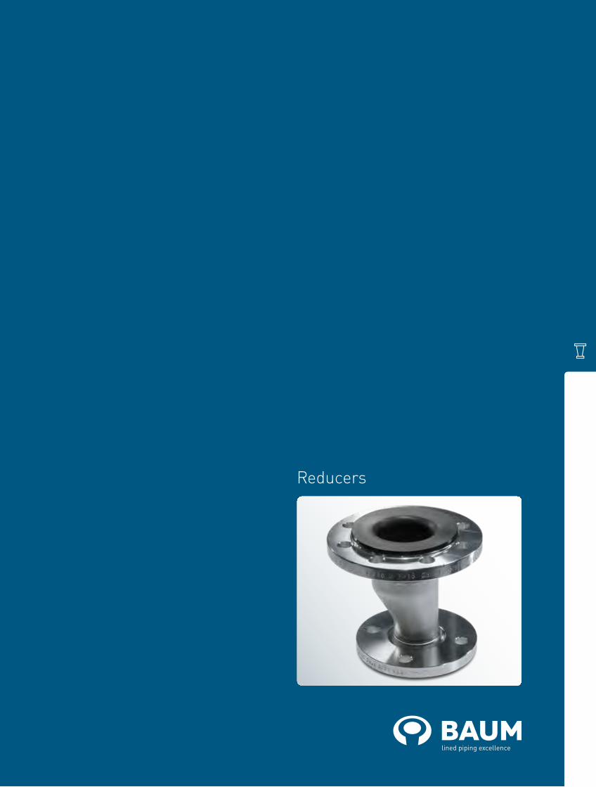
Reducers

Reducing Flanges (Class 150)We have a custom-made solution for transitions between all nominal pipe sizes. Depending on the reduction, lined with PTFE, PFA or PP.

baum-lined-piping.comEnglish version BAUM catalogue ANSI-FR-2018
Reducing Flanges (Class 150)Materials:• carbon steel• stainless steelLining materials:• PTFE (virgin or conductive)• PFA (virgin or conductive)• PPOther pressure rating:• Class 300
continued on the next page
Special features: • earthing stud/lugOptional extras: • final paintingForm K1 (concentric): • NPS1: through holes• NPS2: threaded holesForm K2 (concentric): • NPS1: threaded holes• NPS2: threaded holes
Form K3 (concentric): • NPS1: threaded holes• NPS2: threaded holes on centre line Excentric Reducing Flanges – Form E2 and E3 according to DIN 2848 – on request.
Form K1 Form K2 Form K3
NPS1 NPS2 L
(mm)
Form d4(1)
(mm)
K(1)
(mm)
d4(2)
(mm)
K(2)
(mm)
Liningmaterials
No. of bolts xthread (UNC)
Weights
(ca. kg/piece)NPS1 NPS2
¾“ ½“ 35 K3 42.9 69.9 34.9 60.3 PTFE 4 x ½“ 4 x ½“ 1.8
1“ ½“ 35 K3 50.8 79.4 34.9 60.3 PTFE 4 x ½“ 4 x ½“ 2.2
1“ ¾“ 35 K3 50.8 79.4 42.9 69.9 PTFE 4 x ½“ 4 x ½“ 2.1
1¼“ ¾“ 35 K3 63.5 88.9 42.9 69.9 PTFE 4 x ½“ 4 x ½“ 2.5
1¼“ 1“ 35 K3 63.5 88.9 50.8 79.4 PTFE 4 x ½“ 4 x ½“ 2.5
1½“ ¾“ 35 K2 73.0 98.4 42.9 69.9 PFA 4 x ½“ 4 x ½“ 3.1
1½“ 1“ 35 K3 73.0 98.4 50.8 79.4 PTFE 4 x ½“ 4 x ½“ 3.0
1½“ 1¼“ 35 K3 73.0 98.4 63.5 88.9 PTFE 4 x ½“ 4 x ½“ 3.0
2“ ¾“ 35 K2 92.1 120.7 42.9 69.9 PFA 4 x ⅝“ 4 x ½“ 4.2
2“ 1“ 35 K2 92.1 120.7 50.8 79.4 PFA 4 x ⅝“ 4 x ½“ 4.2
2“ 1¼“ 35 K3 92.1 120.7 63.5 88.9 PTFE 4 x ⅝“ 4 x ½“ 3.8
2“ 1½“ 35 K3 92.1 120.7 73.0 98.4 PTFE 4 x ⅝“ 4 x ½“ 3.8
2½“ ¾“ 35 K2 104.8 139.7 42.9 69.9 PFA 4 x ⅝“ 4 x ½“ 5.8
2½“ 1“ 35 K2 104.8 139.7 50.8 79.4 PFA 4 x ⅝“ 4 x ½“ 5.7
2½“ 1¼“ 35 K2 104.8 139.7 63.5 88.9 PFA 4 x ⅝“ 4 x ½“ 5.6
2½“ 1½“ 35 K3 104.8 139.7 73.0 98.4 PTFE 4 x ⅝“ 4 x ½“ 5.3
2½“ 2“ 35 K3 104.8 139.7 92.1 120.7 PTFE 4 x ⅝“ 4 x ⅝“ 5.2
3“ 1“ 35 K1 127.0 152.4 50.8 79.4 PFA 4 x ⅝“ 4 x ½“ 6.4
3“ 1¼“ 35 K2 127.0 152.4 63.5 88.9 PFA 4 x ⅝“ 4 x ½“ 6.4
3“ 1½“ 35 K2 127.0 152.4 73.0 98.4 PFA 4 x ⅝“ 4 x ½“ 6.3
3“ 2“ 35 K2 127.0 152.4 92.1 120.7 PTFE 4 x ⅝“ 4 x ⅝“ 5.9
3“ 2½“ 35 K2 127.0 152.4 104.8 139.7 PTFE 4 x ⅝“ 4 x ⅝“ 5.8

baum-lined-piping.comEnglish version BAUM catalogue ANSI-FR-2018
Reducing Flanges (Class 150)
continued on the next page
NPS1 NPS2 L
(mm)
Form d4(1)
(mm)
K(1)
(mm)
d4(2)
(mm)
K(2)
(mm)
Lining materials
No. of bolts xthread (UNC)
Weights
(ca. kg/piece)NPS1 NPS2
4“ 1“ 45 K1 157.2 190.5 50.8 79.4 PFA 8 x ⅝“ 4 x ½“ 11.6
4“ 1¼“ 45 K1 157.2 190.5 63.5 88.9 PFA 8 x ⅝“ 4 x ½“ 11.6
4“ 1½“ 45 K1 157.2 190.5 73.0 98.4 PFA 8 x ⅝“ 4 x ½“ 11.5
4“ 2“ 45 K2 157.2 190.5 92.1 120.7 PFA 8 x ⅝“ 4 x ⅝“ 11.4
4“ 2½“ 45 K2 157.2 190.5 104.8 139.7 PTFE 8 x ⅝“ 4 x ⅝“ 10.7
4“ 3“ 45 K3 157.2 190.5 127.0 152.4 PTFE 8 x ⅝“ 4 x ⅝“ 10.5
5“ 1“ 45 K1 185.7 215.9 50.8 79.4 PFA 8 x ¾“ 4 x ½“ 13.8
5“ 1¼“ 45 K1 185.7 215.9 63.5 88.9 PFA 8 x ¾“ 4 x ½“ 13.4
5“ 1½“ 45 K1 185.7 215.9 73.0 98.4 PFA 8 x ¾“ 4 x ½“ 13.4
5“ 2“ 45 K1 185.7 215.9 92.1 120.7 PFA 8 x ¾“ 4 x ⅝“ 13.1
5“ 2½“ 45 K2 185.7 215.9 104.8 139.7 PFA 8 x ¾“ 4 x ⅝“ 12.8
5“ 3“ 45 K2 185.7 215.9 127.0 152.4 PTFE 8 x ¾“ 4 x ⅝“ 11.8
5“ 4“ 45 K3 185.7 215.9 157.2 190.5 PTFE 8 x ¾“ 8 x ⅝“ 11.4
6“ 1“ 45 K1 215.9 241.3 50.8 79.4 PFA 8 x ¾“ 4 x ½“ 16.3
6“ 1¼“ 45 K1 215.9 241.3 63.5 88.9 PFA 8 x ¾“ 4 x ½“ 16.6
6“ 1½“ 45 K1 215.9 241.3 73.0 98.4 PFA 8 x ¾“ 4 x ½“ 16.5
6“ 2“ 45 K1 215.9 241.3 92.1 120.7 PFA 8 x ¾“ 4 x ⅝“ 16.5
6“ 2½“ 45 K1 215.9 241.3 104.8 139.7 PFA 8 x ¾“ 4 x ⅝“ 16.1
6“ 3“ 45 K1 215.9 241.3 127.0 152.4 PFA 8 x ¾“ 4 x ⅝“ 15.6
6“ 4“ 45 K2 215.9 241.3 157.2 190.5 PTFE 8 x ¾“ 8 x ⅝“ 13.7
6“ 5“ 45 K3 215.9 241.3 185.7 215.9 PTFE 8 x ¾“ 8 x ¾“ 13.5
8“ 2“ 45 K1 269.9 298.5 92.1 120.7 PFA 8 x ¾“ 4 x ⅝“ 24.9
8“ 2½“ 45 K1 269.9 298.5 104.8 139.7 PFA 8 x ¾“ 4 x ⅝“ 26.0
8“ 3“ 45 K1 269.9 298.5 127.0 152.4 PFA 8 x ¾“ 4 x ⅝“ 24.9
8“ 4“ 45 K1 269.9 298.5 157.2 190.5 PFA 8 x ¾“ 8 x ⅝“ 25.0
8“ 5“ 45 K1 269.9 298.5 185.7 215.9 PTFE 8 x ¾“ 8 x ¾“ 23.1
8“ 6“ 45 K2 269.9 298.5 215.9 241.3 PTFE 8 x ¾“ 8 x ¾“ 21.9
10“ 2½“ 45 K1 323.8 362.0 104.8 139.7 PFA 12 x ⅞“ 4 x ⅝“ 39.2
10“ 3“ 45 K1 323.8 362.0 127.0 152.4 PFA 12 x ⅞“ 4 x ⅝“ 37.5
10“ 4“ 45 K1 323.8 362.0 157.2 190.5 PFA 12 x ⅞“ 8 x ⅝“ 36.3
10“ 5“ 45 K1 323.8 362.0 185.7 215.9 PTFE 12 x ⅞“ 8 x ¾“ 30.4
10“ 6“ 45 K1 323.8 362.0 215.9 241.3 PTFE 12 x ⅞“ 8 x ¾“ 30.4
10“ 8“ 45 K2 323.8 362.0 269.9 298.5 PTFE 12 x ⅞“ 8 x ¾“ 27.5
12“ 3“ 50 K1 381.0 431.8 127.0 152.4 PTFE 12 x ⅞“ 4 x ⅝“ 55.1
12“ 4“ 50 K1 381.0 431.8 157.2 190.5 PTFE 12 x ⅞“ 8 x ⅝“ 53.4
12“ 5“ 50 K1 381.0 431.8 185.7 215.9 PTFE 12 x ⅞“ 8 x ¾“ 51.0
12“ 6“ 50 K1 381.0 431.8 215.9 241.3 PTFE 12 x ⅞“ 8 x ¾“ 50.8
12“ 8“ 50 K1 381.0 431.8 269.9 298.5 PTFE 12 x ⅞“ 8 x ¾“ 48.9
12“ 10“ 50 K2 381.0 431.8 323.8 362.0 PTFE 12 x ⅞“ 12 x ⅞“ 46.7
14“ 4“ 50 K1 412.8 476.3 157.2 190.5 PTFE 12 x 1“ 8 x ⅝“ 64.3
14“ 5“ 50 K1 412.8 476.3 185.7 215.9 PTFE 12 x 1“ 8 x ¾“ 62.9
14“ 6“ 50 K1 412.8 476.3 215.9 241.3 PTFE 12 x 1“ 8 x ¾“ 62.6
14“ 8“ 50 K1 412.8 476.3 269.9 298.5 PTFE 12 x 1“ 8 x ¾“ 60.8
14“ 10“ 50 K1 412.8 476.3 323.8 362.0 PTFE 12 x 1“ 12 x ⅞“ 56.2
14“ 12“ 50 K2 412.8 476.3 381.0 431.8 PTFE 12 x 1“ 12 x ⅞“ 53.1

baum-lined-piping.comEnglish version BAUM catalogue ANSI-FR-2018
Reducing Flanges (Class 150)
NPSLining thickness Possible vacuum
standard thick-walled 23° C 150° C 200° C
1“
1½“
2“
3“
4“
6“
8“
10“
12“
L = Total lengthd4 = Raised face diameterK = Bolt circle diameterTechnical data valid for the pressure rating Class 150.
Different nominal pipe sizes and total lengths on request.
Vacuum resistance: = full vacuum = limited vacuum = no vacuum
Please refer to the next higher nominal pipe size if your nominal pipe size is not listed.
NPS1 NPS2 L
(mm)
Form d4(1)
(mm)
K(1)
(mm)
d4(2)
(mm)
K(2)
(mm)
Lining materials
No. of bolts xthread (UNC)
Weights
(ca. kg/piece)NPS1 NPS2
16“ 5“ 50 K1 469.9 539.8 185.7 215.9 PTFE 16 x 1“ 8 x ¾“ 84.1
16“ 6“ 50 K1 469.9 539.8 215.9 241.3 PTFE 16 x 1“ 8 x ¾“ 81.7
16“ 8“ 50 K1 469.9 539.8 269.9 298.5 PTFE 16 x 1“ 8 x ¾“ 76.7
16“ 10“ 50 K1 469.9 539.8 323.8 362.0 PTFE 16 x 1“ 12 x ⅞“ 76.4
16“ 12“ 50 K1 469.9 539.8 381.0 431.8 PTFE 16 x 1“ 12 x ⅞“ 68.3
16“ 14“ 50 K2 469.9 539.8 412.8 476.3 PTFE 16 x 1“ 12 x 1“ 63.6
18“ 6“ 50 K1 533.4 577.9 215.9 241.3 PTFE 16 x 1⅛“ 8 x ¾“ 80.2
18“ 8“ 50 K1 533.4 577.9 269.9 298.5 PTFE 16 x 1⅛“ 8 x ¾“ 78.4
18“ 10“ 50 K1 533.4 577.9 323.8 362.0 PTFE 16 x 1⅛“ 12 x ⅞“ 76.1
18“ 12“ 50 K1 533.4 577.9 381.0 431.8 PTFE 16 x 1⅛“ 12 x ⅞“ 73.8
18“ 14“ 50 K1 533.4 577.9 412.8 476.3 PTFE 16 x 1⅛“ 12 x 1“ 72.2
18“ 16“ 50 K2 533.4 577.9 469.9 539.8 PTFE 16 x 1⅛“ 16 x 1“ 69.4
20“ 6“ 50 K1 584.2 635.0 215.9 241.3 PTFE 20 x 1⅛“ 8 x ¾“ 115.0
20“ 8“ 50 K1 584.2 635.0 269.9 298.5 PTFE 20 x 1⅛“ 8 x ¾“ 110.3
20“ 10“ 50 K1 584.2 635.0 323.8 362.0 PTFE 20 x 1⅛“ 12 x ⅞“ 104.5
20“ 12“ 50 K1 584.2 635.0 381.0 431.8 PTFE 20 x 1⅛“ 12 x ⅞“ 100.5
20“ 14“ 50 K1 584.2 635.0 412.8 476.3 PTFE 20 x 1⅛“ 12 x 1“ 95.2
20“ 16“ 50 K1 584.2 635.0 469.9 539.8 PTFE 20 x 1⅛“ 16 x 1“ 87.6
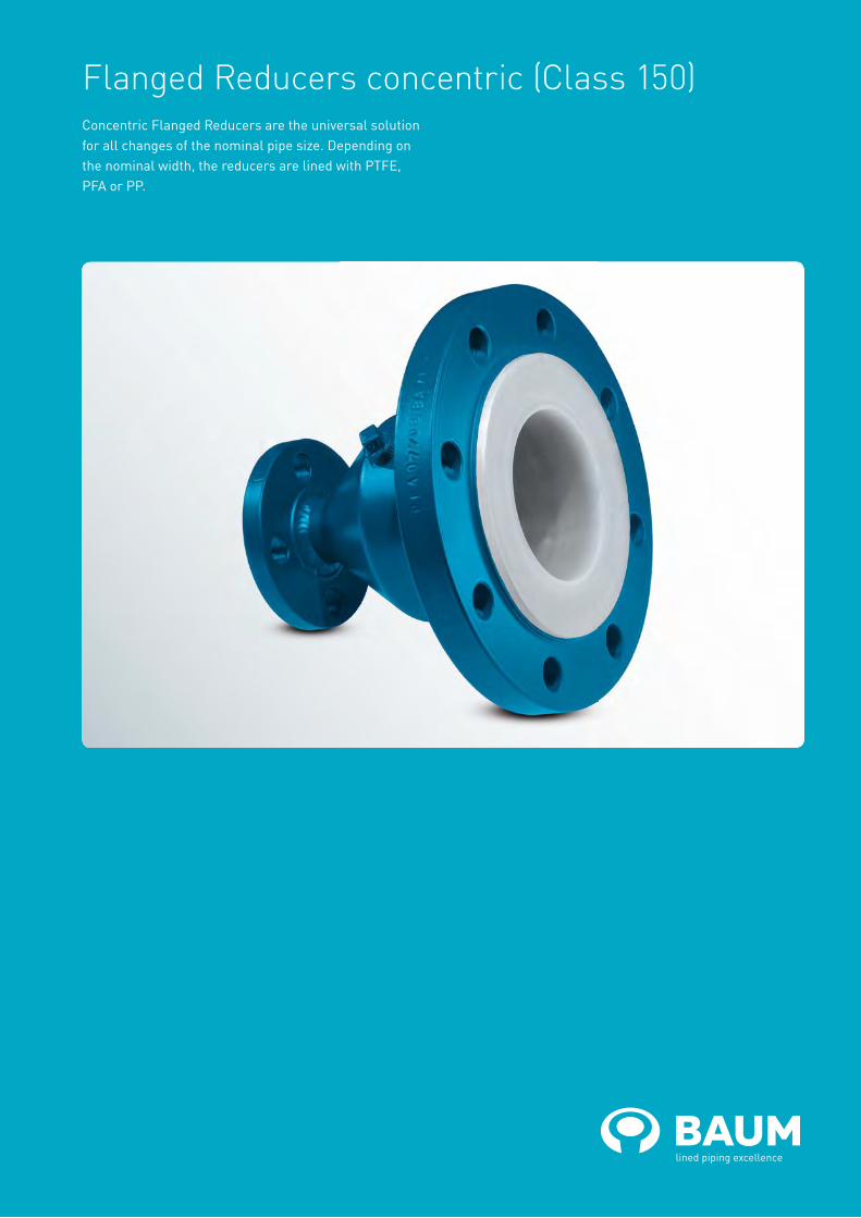
Flanged Reducers concentric (Class 150)Concentric Flanged Reducers are the universal solution for all changes of the nominal pipe size. Depending on the nominal width, the reducers are lined with PTFE, PFA or PP.

baum-lined-piping.comEnglish version BAUM catalogue ANSI-RK-2018
Flanged Reducers concentric (Class 150)Materials:• carbon steel• stainless steelLining materials:• PTFE (virgin or conductive)• PFA (virgin or conductive)• PP
continued on the next page
Flanges:• fix-fix• fix-loose• loose-looseOther pressure rating:• Class 300
Special features: • earthing stud/ lug• vent hole extensionOptional extras: • final painting• non-destructive testing
one-piece two-piece
NPS1 NPS2 L
(mm)
d1(1)
(mm)
d4(1)
(mm)
K(1)
(mm)
smin (1)
(mm)
a1(1)
(mm)
a2(1)
(mm)
d1(2)
(mm)
d4(2)
(mm)
K(2)
(mm)
smin (2)
(mm)
a1(2)
(mm)
a2(2)
(mm)
Lining mate-rials
No. of bolts xthread (UNC)
Wt.
(ca. kg / pc.)
NPS1 NPS2
¾“ ½“ 114 26.7 42.9 69.9 3.0 16.2 19.7 26.7 34.9 60.3 3.0 14.6 18.2 PTFE 4 x ½“ 4 x ½“ 1.5
1“ ½“ 114 33.4 50.8 79.4 3.0 17.7 21.3 26.7 34.9 60.3 3.0 14.6 18.2 PTFE 4 x ½“ 4 x ½“ 1.9
1“ ¾“ 114 33.4 50.8 79.4 3.0 17.7 21.3 26.7 42.9 69.9 3.0 16.2 19.7 PTFE 4 x ½“ 4 x ½“ 2.2
1¼“ ¾“ 114 42.2 63.5 88.9 3.0 19.3 22.9 26.7 42.9 69.9 3.0 16.2 19.7 PTFE 4 x ½“ 4 x ½“ 2.7
1¼“ 1“ 114 42.2 63.5 88.9 3.0 19.3 22.9 33.4 50.8 79.4 3.0 17.7 21.3 PTFE 4 x ½“ 4 x ½“ 3.0
1½“ ¾“ 114 48.3 73.0 98.4 4.0 21.9 25.5 26.7 42.9 69.9 4.0 17.2 20.7 PFA 4 x ½“ 4 x ½“ 2.9
1½“ 1“ 114 48.3 73.0 98.4 3.0 20.9 24.5 33.4 50.8 79.4 3.0 17.7 21.3 PTFE 4 x ½“ 4 x ½“ 3.3
1½“ 1¼“ 114 48.3 73.0 98.4 3.0 20.9 24.5 42.2 63.5 88.9 3.0 19.3 22.9 PTFE 4 x ½“ 4 x ½“ 3.7
2“ 1“ 127 60.3 92.1 120.7 4.0 23.5 27.6 33.4 50.8 79.4 4.0 18.7 22.3 PFA 4 x ⅝“ 4 x ½“ 4.5
2“ 1¼“ 127 60.3 92.1 120.7 3.0 22.5 26.6 42.2 63.5 88.9 3.0 19.3 22.9 PTFE 4 x ⅝“ 4 x ½“ 5.0
2“ 1½“ 127 60.3 92.1 120.7 3.0 22.5 26.6 48.3 73.0 98.4 3.0 20.9 24.5 PTFE 4 x ⅝“ 4 x ½“ 5.0
2½“ 1¼“ 140 73.0 104.8 139.7 4.0 26.7 31.5 42.2 63.5 88.9 4.0 20.3 23.9 PFA 4 x ⅝“ 4 x ½“ 6.4
2½“ 1½“ 140 73.0 104.8 139.7 4.0 26.7 31.5 48.3 73.0 98.4 4.0 21.9 25.5 PTFE 4 x ⅝“ 4 x ½“ 6.6
2½“ 2“ 140 73.0 104.8 139.7 4.0 26.7 31.5 60.3 92.1 120.7 4.0 23.5 27.6 PTFE 4 x ⅝“ 4 x ⅝“ 7.6
3“ 1“ 152 88.9 127.0 152.4 4.0 28.3 33.4 33.4 50.8 79.4 4.0 18.7 22.3 PFA 4 x ⅝“ 4 x ½“ 7.0
3“ 1½“ 152 88.9 127.0 152.4 4.0 28.3 33.4 48.3 73.0 98.4 4.0 21.9 25.5 PFA 4 x ⅝“ 4 x ½“ 7.9
3“ 2“ 152 88.9 127.0 152.4 3.0 27.3 32.4 60.3 92.1 120.7 3.0 22.5 26.6 PTFE 4 x ⅝“ 4 x ⅝“ 8.7
3“ 2½“ 152 88.9 127.0 152.4 3.0 27.3 32.4 73.0 104.8 139.7 3.0 25.7 30.5 PTFE 4 x ⅝“ 4 x ⅝“ 10.5
4“ 2“ 178 114.3 157.2 190.5 4.0 28.3 33.9 60.3 92.1 120.7 4.0 23.5 27.6 PFA 8 x ⅝“ 4 x ⅝“ 11.4
4“ 2½“ 178 114.3 157.2 190.5 4.5 28.8 34.4 73.0 104.8 139.7 4.5 27.2 32.0 PTFE 8 x ⅝“ 4 x ⅝“ 13.3
4“ 3“ 178 114.3 157.2 190.5 4.5 28.8 34.4 88.9 127.0 152.4 4.5 28.8 33.9 PTFE 8 x ⅝“ 4 x ⅝“ 14.3
5“ 2½“ 203 141.3 185.7 215.9 4.0 28.3 34.5 73.0 104.8 139.7 4.0 26.7 31.5 PFA 8 x ¾“ 4 x ⅝“ 15.6
5“ 3“ 203 141.3 185.7 215.9 4.0 28.3 34.5 88.9 127.0 152.4 4.0 28.3 33.4 PFA 8 x ¾“ 4 x ⅝“ 16.6
5“ 4“ 203 141.3 185.7 215.9 4.5 28.8 35.0 114.3 157.2 190.5 4.5 28.8 34.4 PTFE 8 x ¾“ 8 x ⅝“ 19.0

baum-lined-piping.comEnglish version BAUM catalogue ANSI-RK-2018
Flanged Reducers concentric (Class 150)
NPS1
Lining thickness Possible vacuum
standard thick-walled 23° C 150° C 200° C
1“
Bitt
e Rü
cksp
rach
e
1½“
2“
3“
4“
6“
8“
10“
12“
L = Total lengthd1 = Outer diameter of the piped4 = Raised face diameterK = Bolt circle diametersmin = Minimum flare thicknessa1 = Minimum length with fixed flange and smin
a2 = Minimum length with loose flange and smin
Technical data valid for the pressure rating Class 150. a1 and a2 depend on construction type and lining thickness.
The nominal pipe size combinations printed in bold are manufactured in two parts with flanges fix-fix or fix-loose in which the loose flange is generally on the NPS1 side.
Different nominal pipe sizes and total lengths on request.
Vacuum resistance: = full vacuum = limited vacuum = no vacuum
Please refer to the next higher nominal pipe size if your nominal pipe size is not listed.
NPS1 NPS2 L
(mm)
d1(1)
(mm)
d4(1)
(mm)
K(1)
(mm)
smin (1)
(mm)
a1(1)
(mm)
a2(1)
(mm)
d1(2)
(mm)
d4(2)
(mm)
K(2)
(mm)
smin (2)
(mm)
a1(2)
(mm)
a2(2)
(mm)
Lining mate-ri-
als
No. of bolts xthread (UNC)
Wt.
(ca. kg / pc.)
NPS1 NPS2
6“ 3“ 229 168.3 215.9 241.3 4.0 29.9 36.5 88.9 127.0 152.4 4.0 28.3 33.4 PFA 8 x ¾“ 4 x ⅝“ 20.4
6“ 4“ 229 168.3 215.9 241.3 6.0 31.9 38.5 114.3 157.2 190.5 6.0 30.3 35.9 PTFE 8 x ¾“ 8 x ⅝“ 22.9
6“ 5“ 229 168.3 215.9 241.3 6.0 31.9 38.5 141.3 185.7 215.9 6.0 30.3 36.5 PTFE 8 x ¾“ 8 x ¾“ 24.0
8“ 4“ 279 219.1 269.9 298.5 6.0 35.0 42.8 114.3 157.2 190.5 6.0 30.3 35.9 PTFE 8 x ¾“ 8 x ⅝“ 46.3
8“ 5“ 279 219.1 269.9 298.5 6.0 35.0 42.8 141.3 185.7 215.9 6.0 30.3 36.5 PTFE 8 x ¾“ 8 x ¾“ 51.6
8“ 6“ 279 219.1 269.9 298.5 6.0 35.0 42.8 168.3 215.9 241.3 6.0 31.9 38.5 PTFE 8 x ¾“ 8 x ¾“ 39.2
10“ 5“ 305 273.0 323.8 362.0 6.0 36.6 45.5 141.3 185.7 215.9 6.0 30.3 36.5 PTFE 12 x ⅞“ 8 x ¾“ 62.1
10“ 6“ 305 273.0 323.8 362.0 6.0 36.6 45.5 168.3 215.9 241.3 6.0 31.9 38.5 PTFE 12 x ⅞“ 8 x ¾“ 70.4
10“ 8“ 305 273.0 323.8 362.0 6.0 36.6 45.5 219.1 269.9 298.5 6.0 35.0 42.8 PTFE 12 x ⅞“ 8 x ¾“ 60.1
12“ 6“ 356 323.8 381.0 431.8 6.0 38.2 48.1 168.3 215.9 241.3 6.0 31.9 38.5 PTFE 12 x ⅞“ 8 x ¾“ 89.1
12“ 8“ 356 323.8 381.0 431.8 6.0 38.2 48.1 219.1 269.9 298.5 6.0 35.0 42.8 PTFE 12 x ⅞“ 8 x ¾“ 105.6
12“ 10“ 356 323.8 381.0 431.8 6.0 38.2 48.1 273.0 323.8 362.0 6.0 36.6 45.5 PTFE 12 x ⅞“ 12 x ⅞“ 88.4
14“ 8“ 406 355.6 412.8 476.3 7.5 42.9 57.5 219.1 269.9 298.5 7.5 36.5 44.3 PTFE 12 x 1“ 8 x ¾“ 123.2
14“ 10“ 406 355.6 412.8 476.3 7.5 42.9 57.5 273.0 323.8 362.0 7.5 38.1 47.0 PTFE 12 x 1“ 12 x ⅞“ 136.1
14“ 12“ 406 355.6 412.8 476.3 7.5 42.9 57.5 323.8 381.0 431.8 7.5 39.7 49.6 PTFE 12 x 1“ 12 x ⅞“ 122.3
16“ 10“ 457 406.4 469.9 539.8 7.5 44.5 59.1 273.0 323.8 362.0 7.5 38.1 47.0 PTFE 16 x 1“ 12 x ⅞“ 157.4
16“ 12“ 457 406.4 469.9 539.8 7.5 44.5 59.1 323.8 381.0 431.8 7.5 39.7 49.6 PTFE 16 x 1“ 12 x ⅞“ 188.3
16“ 14“ 457 406.4 469.9 539.8 7.5 44.5 59.1 355.6 412.8 476.3 7.5 42.9 57.5 PTFE 16 x 1“ 12 x 1“ 157.9
18“ 10“ 483 457.0 533.4 577.9 8.0 48.1 62.7 273.0 323.8 362.0 8.0 38.6 47.5 PTFE 16 x 1⅛“ 12 x ⅞“ 170.2
18“ 12“ 483 457.0 533.4 577.9 8.0 48.1 62.7 323.8 381.0 431.8 8.0 40.2 50.1 PTFE 16 x 1⅛“ 12 x ⅞“ 201.3
18“ 14“ 483 457.0 533.4 577.9 8.0 48.1 62.7 355.6 412.8 476.3 8.0 43.4 58.0 PTFE 16 x 1⅛“ 12 x 1“ 171.0
20“ 12“ 508 508.0 584.2 635.0 8.0 51.3 65.9 323.8 381.0 431.8 8.0 40.2 50.1 PTFE 20 x 1⅛“ 12 x ⅞“ 224.1
20“ 14“ 508 508.0 584.2 635.0 8.0 51.3 65.9 355.6 412.8 476.3 8.0 43.4 58.0 PTFE 20 x 1⅛“ 12 x 1“ 255.3
20“ 16“ 508 508.0 584.2 635.0 8.0 51.3 65.9 406.4 469.9 539.8 8.0 45.0 59.6 PTFE 20 x 1⅛“ 16 x 1“ 211.3

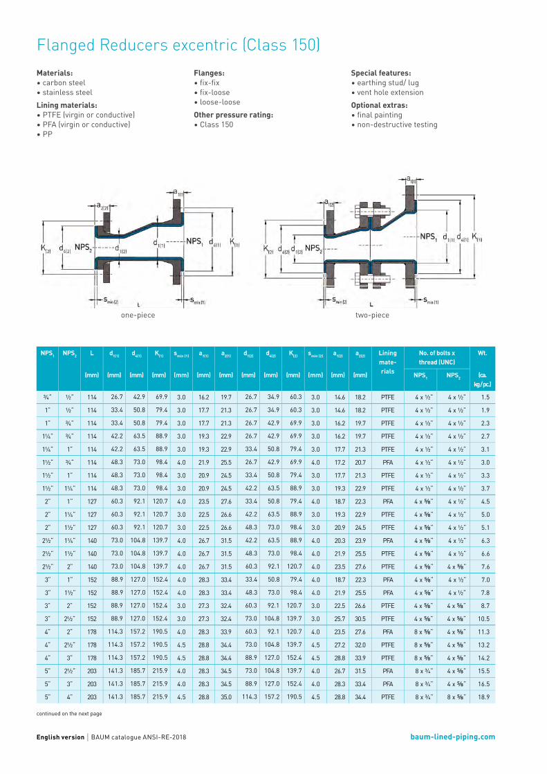
Flanged Reducers excentric (Class 150)In case of horizontal installation, excentric Flanged Reducers enable the complete draining of pipe sections. Depending on the nominal width, the reducers are lined with PTFE, PFA or PP.
baum-lined-piping.comEnglish version BAUM catalogue ANSI-RE-2018
Flanged Reducers excentric (Class 150)Materials:• carbon steel• stainless steelLining materials:• PTFE (virgin or conductive)• PFA (virgin or conductive)• PP
continued on the next page
Flanges:• fix-fix• fix-loose• loose-looseOther pressure rating:• Class 150
Special features: • earthing stud/ lug• vent hole extensionOptional extras: • final painting• non-destructive testing
one-piece two-piece
NPS1 NPS2 L
(mm)
d1(1)
(mm)
d4(1)
(mm)
K(1)
(mm)
smin (1)
(mm)
a1(1)
(mm)
a2(1)
(mm)
d1(2)
(mm)
d4(2)
(mm)
K(2)
(mm)
smin (2)
(mm)
a1(2)
(mm)
a2(2)
(mm)
Lining mate-rials
No. of bolts xthread (UNC)
Wt.
(ca. kg / pc.)
NPS1 NPS2
¾“ ½“ 114 26.7 42.9 69.9 3.0 16.2 19.7 26.7 34.9 60.3 3.0 14.6 18.2 PTFE 4 x ½“ 4 x ½“ 1.5
1“ ½“ 114 33.4 50.8 79.4 3.0 17.7 21.3 26.7 34.9 60.3 3.0 14.6 18.2 PTFE 4 x ½“ 4 x ½“ 1.9
1“ ¾“ 114 33.4 50.8 79.4 3.0 17.7 21.3 26.7 42.9 69.9 3.0 16.2 19.7 PTFE 4 x ½“ 4 x ½“ 2.3
1¼“ ¾“ 114 42.2 63.5 88.9 3.0 19.3 22.9 26.7 42.9 69.9 3.0 16.2 19.7 PTFE 4 x ½“ 4 x ½“ 2.7
1¼“ 1“ 114 42.2 63.5 88.9 3.0 19.3 22.9 33.4 50.8 79.4 3.0 17.7 21.3 PTFE 4 x ½“ 4 x ½“ 3.1
1½“ ¾“ 114 48.3 73.0 98.4 4.0 21.9 25.5 26.7 42.9 69.9 4.0 17.2 20.7 PFA 4 x ½“ 4 x ½“ 3.0
1½“ 1“ 114 48.3 73.0 98.4 3.0 20.9 24.5 33.4 50.8 79.4 3.0 17.7 21.3 PTFE 4 x ½“ 4 x ½“ 3.3
1½“ 1¼“ 114 48.3 73.0 98.4 3.0 20.9 24.5 42.2 63.5 88.9 3.0 19.3 22.9 PTFE 4 x ½“ 4 x ½“ 3.7
2“ 1“ 127 60.3 92.1 120.7 4.0 23.5 27.6 33.4 50.8 79.4 4.0 18.7 22.3 PFA 4 x ⅝“ 4 x ½“ 4.5
2“ 1¼“ 127 60.3 92.1 120.7 3.0 22.5 26.6 42.2 63.5 88.9 3.0 19.3 22.9 PTFE 4 x ⅝“ 4 x ½“ 5.0
2“ 1½“ 127 60.3 92.1 120.7 3.0 22.5 26.6 48.3 73.0 98.4 3.0 20.9 24.5 PTFE 4 x ⅝“ 4 x ½“ 5.1
2½“ 1¼“ 140 73.0 104.8 139.7 4.0 26.7 31.5 42.2 63.5 88.9 4.0 20.3 23.9 PFA 4 x ⅝“ 4 x ½“ 6.3
2½“ 1½“ 140 73.0 104.8 139.7 4.0 26.7 31.5 48.3 73.0 98.4 4.0 21.9 25.5 PTFE 4 x ⅝“ 4 x ½“ 6.6
2½“ 2“ 140 73.0 104.8 139.7 4.0 26.7 31.5 60.3 92.1 120.7 4.0 23.5 27.6 PTFE 4 x ⅝“ 4 x ⅝“ 7.6
3“ 1“ 152 88.9 127.0 152.4 4.0 28.3 33.4 33.4 50.8 79.4 4.0 18.7 22.3 PFA 4 x ⅝“ 4 x ½“ 7.0
3“ 1½“ 152 88.9 127.0 152.4 4.0 28.3 33.4 48.3 73.0 98.4 4.0 21.9 25.5 PFA 4 x ⅝“ 4 x ½“ 7.8
3“ 2“ 152 88.9 127.0 152.4 3.0 27.3 32.4 60.3 92.1 120.7 3.0 22.5 26.6 PTFE 4 x ⅝“ 4 x ⅝“ 8.7
3“ 2½“ 152 88.9 127.0 152.4 3.0 27.3 32.4 73.0 104.8 139.7 3.0 25.7 30.5 PTFE 4 x ⅝“ 4 x ⅝“ 10.5
4“ 2“ 178 114.3 157.2 190.5 4.0 28.3 33.9 60.3 92.1 120.7 4.0 23.5 27.6 PFA 8 x ⅝“ 4 x ⅝“ 11.3
4“ 2½“ 178 114.3 157.2 190.5 4.5 28.8 34.4 73.0 104.8 139.7 4.5 27.2 32.0 PTFE 8 x ⅝“ 4 x ⅝“ 13.2
4“ 3“ 178 114.3 157.2 190.5 4.5 28.8 34.4 88.9 127.0 152.4 4.5 28.8 33.9 PTFE 8 x ⅝“ 4 x ⅝“ 14.2
5“ 2½“ 203 141.3 185.7 215.9 4.0 28.3 34.5 73.0 104.8 139.7 4.0 26.7 31.5 PFA 8 x ¾“ 4 x ⅝“ 15.5
5“ 3“ 203 141.3 185.7 215.9 4.0 28.3 34.5 88.9 127.0 152.4 4.0 28.3 33.4 PFA 8 x ¾“ 4 x ⅝“ 16.5
5“ 4“ 203 141.3 185.7 215.9 4.5 28.8 35.0 114.3 157.2 190.5 4.5 28.8 34.4 PTFE 8 x ¾“ 8 x ⅝“ 18.9
baum-lined-piping.comEnglish version BAUM catalogue ANSI-RE-2018
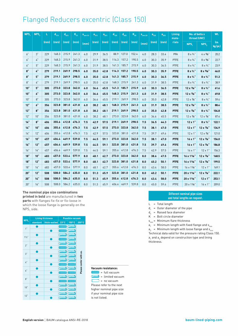
Flanged Reducers excentric (Class 150)
NPS1
Lining thickness Possible vacuum
standard thick-walled 23° C 150° C 200° C
1“
Plea
se c
onfe
r with
us.
1½“
2“
3“
4“
6“
8“
10“
12“
L = Total lengthd1 = Outer diameter of the piped4 = Raised face diameterK = Bolt circle diametersmin = Minimum flare thicknessa1 = Minimum length with fixed flange and smin
a2 = Minimum length with loose flange and smin
Technical data valid for the pressure rating Class 150. a1 and a2 depend on construction type and lining thickness.
Different nominal pipe sizes and total lengths on request.
The nominal pipe size combinations printed in bold are manufactured in two parts with flanges fix-fix or fix-loose in which the loose flange is generally on the NPS1 side.
Vacuum resistance: = full vacuum = limited vacuum = no vacuum
Please refer to the next higher nominal pipe size if your nominal pipe size is not listed.
NPS1 NPS2 L
(mm)
d1(1)
(mm)
d4(1)
(mm)
K(1)
(mm)
smin (1)
(mm)
a1(1)
(mm)
a2(1)
(mm)
d1(2)
(mm)
d4(2)
(mm)
K(2)
(mm)
smin (2)
(mm)
a1(2)
(mm)
a2(2)
(mm)
Lining mate- rials
No. of bolts xthread (UNC)
Wt.
(ca. kg / pc.)
NPS1 NPS2
6“ 3“ 229 168.3 215.9 241.3 4.0 29.9 36.5 88.9 127.0 152.4 4.0 28.3 33.4 PFA 8 x ¾“ 4 x ⅝“ 20.2
6“ 4“ 229 168.3 215.9 241.3 6.0 31.9 38.5 114.3 157.2 190.5 6.0 30.3 35.9 PTFE 8 x ¾“ 8 x ⅝“ 22.7
6“ 5“ 229 168.3 215.9 241.3 6.0 31.9 38.5 141.3 185.7 215.9 6.0 30.3 36.5 PTFE 8 x ¾“ 8 x ¾“ 23.9
8“ 4“ 279 219.1 269.9 298.5 6.0 35.0 42.8 114.3 157.2 190.5 6.0 30.3 35.9 PTFE 8 x ¾“ 8 x ⅝“ 46.0
8“ 5“ 279 219.1 269.9 298.5 6.0 35.0 42.8 141.3 185.7 215.9 6.0 30.3 36.5 PTFE 8 x ¾“ 8 x ¾“ 51.3
8“ 6“ 279 219.1 269.9 298.5 6.0 35.0 42.8 168.3 215.9 241.3 6.0 31.9 38.5 PTFE 8 x ¾“ 8 x ¾“ 38.9
10“ 5“ 305 273.0 323.8 362.0 6.0 36.6 45.5 141.3 185.7 215.9 6.0 30.3 36.5 PTFE 12 x ⅞“ 8 x ¾“ 61.6
10“ 6“ 305 273.0 323.8 362.0 6.0 36.6 45.5 168.3 215.9 241.3 6.0 31.9 38.5 PTFE 12 x ⅞“ 8 x ¾“ 69.8
10“ 8“ 305 273.0 323.8 362.0 6.0 36.6 45.5 219.1 269.9 298.5 6.0 35.0 42.8 PTFE 12 x ⅞“ 8 x ¾“ 59.4
12“ 6“ 356 323.8 381.0 431.8 6.0 38.2 48.1 168.3 215.9 241.3 6.0 31.9 38.5 PTFE 12 x ⅞“ 8 x ¾“ 88.4
12“ 8“ 356 323.8 381.0 431.8 6.0 38.2 48.1 219.1 269.9 298.5 6.0 35.0 42.8 PTFE 12 x ⅞“ 8 x ¾“ 104.8
12“ 10“ 356 323.8 381.0 431.8 6.0 38.2 48.1 273.0 323.8 362.0 6.0 36.6 45.5 PTFE 12 x ⅞“ 12 x ⅞“ 87.4
14“ 8“ 406 355.6 412.8 476.3 7.5 42.9 57.5 219.1 269.9 298.5 7.5 36.5 44.3 PTFE 12 x 1“ 8 x ¾“ 122.1
14“ 10“ 406 355.6 412.8 476.3 7.5 42.9 57.5 273.0 323.8 362.0 7.5 38.1 47.0 PTFE 12 x 1“ 12 x ⅞“ 134.9
14“ 12“ 406 355.6 412.8 476.3 7.5 42.9 57.5 323.8 381.0 431.8 7.5 39.7 49.6 PTFE 12 x 1“ 12 x ⅞“ 121.0
16“ 10“ 457 406.4 469.9 539.8 7.5 44.5 59.1 273.0 323.8 362.0 7.5 38.1 47.0 PTFE 16 x 1“ 12 x ⅞“ 156.0
16“ 12“ 457 406.4 469.9 539.8 7.5 44.5 59.1 323.8 381.0 431.8 7.5 39.7 49.6 PTFE 16 x 1“ 12 x ⅞“ 186.8
16“ 14“ 457 406.4 469.9 539.8 7.5 44.5 59.1 355.6 412.8 476.3 7.5 42.9 57.5 PTFE 16 x 1“ 12 x 1“ 156.3
18“ 10“ 483 457.0 533.4 577.9 8.0 48.1 62.7 273.0 323.8 362.0 8.0 38.6 47.5 PTFE 16 x 1⅛“ 12 x ⅞“ 168.5
18“ 12“ 483 457.0 533.4 577.9 8.0 48.1 62.7 323.8 381.0 431.8 8.0 40.2 50.1 PTFE 16 x 1⅛“ 12 x ⅞“ 199.5
18“ 14“ 483 457.0 533.4 577.9 8.0 48.1 62.7 355.6 412.8 476.3 8.0 43.4 58.0 PTFE 16 x 1⅛“ 12 x 1“ 169.1
20“ 12“ 508 508.0 584.2 635.0 8.0 51.3 65.9 323.8 381.0 431.8 8.0 40.2 50.1 PTFE 20 x 1⅛“ 12 x ⅞“ 222.1
20“ 14“ 508 508.0 584.2 635.0 8.0 51.3 65.9 355.6 412.8 476.3 8.0 43.4 58.0 PTFE 20 x 1⅛“ 12 x 1“ 253.1
20“ 16“ 508 508.0 584.2 635.0 8.0 51.3 65.9 406.4 469.9 539.8 8.0 45.0 59.6 PTFE 20 x 1⅛“ 16 x 1“ 209.0

Valves

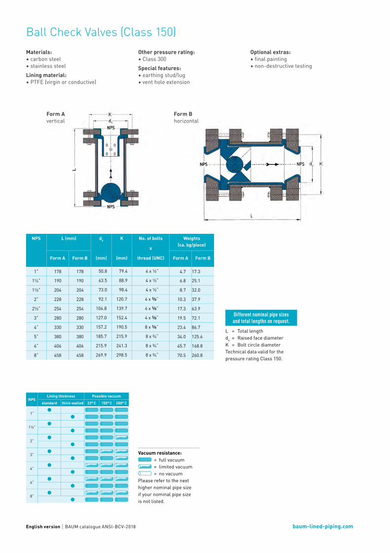
Ball Check Valves (Class 150)Ball Check Valves for horizontal or vertical installation reliably prevent the reverse flow of working medium. At the same time, they offer the least possible resistance in the direction of flow.
baum-lined-piping.comEnglish version BAUM catalogue ANSI-BCV-2018
Ball Check Valves (Class 150)Materials:• carbon steel• stainless steelLining material:• PTFE (virgin or conductive)
Other pressure rating:• Class 300Special features: • earthing stud/lug• vent hole extension
L = Total lengthd4 = Raised face diameterK = Bolt circle diameterTechnical data valid for the pressure rating Class 150.
NPSLining thickness Possible vacuum
standard thick-walled 23° C 150° C 200° C
1“
1½“
2“
3“
4“
6“
8“
Optional extras: • final painting• non-destructive testing
Form Avertical
Form Bhorizontal
Different nominal pipe sizesand total lengths on request.
Vacuum resistance: = full vacuum = limited vacuum = no vacuum
Please refer to the next higher nominal pipe size if your nominal pipe size is not listed.
NPS L (mm) d4
(mm)
K
(mm)
No. of bolts
x
thread (UNC)
Weights(ca. kg/piece)
Form A Form B Form A Form B
1“ 178 178 50.8 79.4 4 x ½“ 4.7 17.3
1¼“ 190 190 63.5 88.9 4 x ½“ 6.8 25.1
1½“ 204 204 73.0 98.4 4 x ½“ 8.7 32.0
2“ 228 228 92.1 120.7 4 x ⅝“ 10.3 37.9
2½“ 254 254 104.8 139.7 4 x ⅝“ 17.3 63.9
3“ 280 280 127.0 152.4 4 x ⅝“ 19.5 72.1
4“ 330 330 157.2 190.5 8 x ⅝“ 23.4 86.7
5“ 380 380 185.7 215.9 8 x ¾“ 34.0 125.6
6“ 406 406 215.9 241.3 8 x ¾“ 45.7 168.8
8“ 458 458 269.9 298.5 8 x ¾“ 70.5 260.8

Bull‘s Eye Sight Indicators (Class 150)Our Bull‘s Eye Sight Indicators – manufactured with high-quality borosilicate glasses – offer you the right view at any time.

baum-lined-piping.comEnglish version BAUM catalogue ANSI-SI-2018
Bull‘s Eye Sight Indicators (Class 150)Flange:• fix-fix• fix-loose• loose-looseOther pressure rating:• Class 300
Special features: • earthing stud/lug• vent hole extension• flange stopper Optional extras: • final painting• non-destructive testing
NPSLining thickness Possible vacuum
standard thick-walled 23° C 150° C 200° C
1“
1½“
2“
3“
4“
NPSLining thickness Possible vacuum
standard thick-walled 23° C 150° C 200° C
6“
8“
10“
12“
L = Total lengthd1 = Outer diameter of the piped4 = Raised face diameterK = Bolt circle diametersmin = Minimum flare thicknessa1 = Mindestlänge bei
Minimum length with fixed flange and smin
a2 = Minimum length with loose flange and smin
Technical data valid for the pressure rating Class 150. a1 and a2 depend on construc-tion type and lining thickness.
Form A Form B
Different nominal pipe sizesand total lengths on request.
Vacuum resistance: = full vacuum = limited vacuum = no vacuum
Please refer to the next higher nominal pipe size if your nominal pipe size is not listed.
Materials:• carbon steel• stainless steelLining materials:• up to nominal pipe size NPS 4“: PFA
(virgin or conductive)• from nominal pipe size NPS 5“: PTFE
(virgin or conductive)• up to nominal pipe size NPS 12“: PP
NPS L
(mm)
Form
(mm)
d1
(mm)
d4
(mm)
K
(mm)
smin
(mm)
a1
(mm)
a2
(mm)
No. of boltsx
thread (UNC)
Weights
(ca. kg/ piece)
1“ 89 A 33.4 50.8 79.4 4.0 18.7 22.3 4 x ½“ 6.1
1¼“ 95 A 42.2 63.5 88.9 4.0 20.3 23.9 4 x ½“ 9.6
1½“ 102 A 48.3 73.0 98.4 4.0 21.9 25.5 4 x ½“ 11.3
2“ 114 A 60.3 92.1 120.7 4.0 23.5 27.6 4 x ⅝“ 15.5
2½“ 127 A 73.0 104.8 139.7 4.0 26.7 31.5 4 x ⅝“ 20.7
3“ 140 A 88.9 127.0 152.4 4.0 28.3 33.4 4 x ⅝“ 24.4
4“ 165 A 114.3 157.2 190.5 4.0 28.3 33.9 8 x ⅝“ 32.2
5“ 190 B 141.3 185.7 215.9 5.0 29.3 35.5 8 x ¾“ 62.7
6“ 203 B 168.3 215.9 241.3 7.0 31.9 38.5 8 x ¾“ 82.5
8“ 229 B 219.1 269.9 298.5 6.0 35.0 42.8 8 x ¾“ 118.2
10“ 280 B 273.0 323.8 362.0 7.5 38.1 47.0 12 x ⅞“ 164.0
12“ 305 B 323.8 381.0 431.8 7.5 39.7 49.6 12 x ⅞“ 213.1
14“ 356 B 355.6 412.8 476.3 10.0 45.4 60.0 12 x 1“ 296.3
16“ 381 B 406.4 469.9 539.8 7.0 44.0 58.6 16 x 1“ 393.7

Blind Flanges

Blind Flanges (Class 150)Any piping needs cleaning connections and also additional connections. Blind flanges close these connections during regular operation.

baum-lined-piping.comEnglish version BAUM catalogue ANSI-FB-2018
Blind Flanges (Class 150)Materials:• carbon steel• stainless steelLining materials:• PTFE (virgin or conductive)• PP (up to nominal pipe size NPS 12“)
Other pressure rating:• Class 300Special features: • earthing stud/lugOptional extras: • final painting
NPSLining thickness Possible vacuum
standard thick-walled 23° C 150° C 200° C
1“
1½“
2“
3“
4“
6“
8“
10“
12“
Vacuum resistance: = full vacuum = limited vacuum = no vacuum
Please refer to the next higher nominal pipe size if your nominal pipe size is not listed.
L = Total lengthd8 = Outer diameterK = Bolt circle diameters = Lining thickness
Technical data valid for the pressure rating Class 150. L depend on construction type and lining thickness.
Different nominal pipe sizes, total lengths and other construction types on request.
NPS L
(mm)
d8
(mm)
K
(mm)
s
(mm)
No. of boltsx
thread (UNC)
Weights
(ca. kg/piece)
½“ 13.6 90 60.3 4.0 4 x ½“ 0.5
¾“ 15.2 100 69.9 4.0 4 x ½“ 0.7
1“ 16.7 110 79.4 4.0 4 x ½“ 1.0
1¼“ 18.3 115 88.9 4.0 4 x ½“ 1.2
1½“ 19.9 125 98.4 4.0 4 x ½“ 1.5
2“ 21.5 150 120.7 4.0 4 x ⅝“ 2.4
2½“ 24.7 180 139.7 4.0 4 x ⅝“ 4.2
3“ 26.3 190 152.4 4.0 4 x ⅝“ 5.0
4“ 27.3 230 190.5 5.0 8 x ⅝“ 7.3
5“ 27.3 255 215.9 5.0 8 x ¾“ 8.9
6“ 28.9 280 241.3 5.0 8 x ¾“ 11.6
8“ 32.0 345 298.5 5.0 8 x ¾“ 20.2
10“ 33.6 405 362.0 5.0 12 x ⅞“ 28.9
12“ 35.2 485 431.8 5.0 12 x ⅞“ 44.3
14“ 38.4 535 476.3 5.0 12 x 1“ 59.4
16“ 40.0 595 539.8 5.0 16 x 1“ 76.6
18“ 43.1 635 577.9 5.0 16 x 1⅛“ 94.3
20“ 46.3 700 635.0 5.0 20 x 1⅛“ 123.8

Expansion Joints

PTFE Expansion Joints, 1 convolute (Class 150)Our PTFE Expansion Joints are highly flexible and provide compensation of vibrations and heat-induced expansion in your production line. PTFE Expansion Joints with 1 convolute allow high working pressures.

baum-lined-piping.comEnglish version BAUM catalogue ANSI-EJ1-2018
PTFE Expansion Joints, 1 convolute (Class 150) - new designDesigns:• up to nominal pipe size NPS 4“ with two ears• from nominal pipe size NPS 5“ with three ears• up to nominal pipe size NPS 2 1/2” with threaded holes• from nominal pipe size NPS 3” with through holesFlange materials:• carbon steel• stainless steelLining material:• PTFE (virgin or conductive)
Flanges:• loose-looseOther pressure ratings: • on requestSpecial features: • limit bolts/hole extensions• earthing stud/lugOptional extras: • final painting
NPS Overpressure resistance (105 Pa) at
Vacuum resistance(105 Pa) at
23° C 100° C 150° C 200° C 23° C 100° C 150° C 200° C
½“ 10.0 10.0 8.3 5.8 -1.00 -1.00 -1.00 -1.00
¾“ 10.0 10.0 8.3 5.8 -1.00 -1.00 -1.00 -1.00
1“ 10.0 10.0 8.3 5.8 -1.00 -1.00 -1.00 -1.00
1¼“ 10.0 10.0 8.3 5.8 -1.00 -1.00 -1.00 -1.00
1½“ 10.0 10.0 8.3 5.8 -1.00 -1.00 -1.00 -1.00
2“ 10.0 10.0 8.3 5.8 -1.00 -1.00 -1.00 -1.00
2½“ 10.0 10.0 8.3 5.8 -1.00 -1.00 -1.00 -1.00
3“ 10.0 10.0 8.3 5.8 -1.00 -1.00 -1.00 -1.00
4“ 10.0 10.0 8.3 5.8 -1.00 -1.00 -1.00 -1.00
5“ 10.0 9.2 6.9 4.8 -1.00 -1.00 -1.00 -0.80
6“ 10.0 9.2 6.9 4.8 -1.00 -1.00 -1.00 -0.80
8“ 10.0 7.7 5.8 4.0 -1.00 -1.00 -1.00 -0.70
10“ 10.0 6.0 4.5 3.2 -1.00 -1.00 -0.80 -0.55
12“ 10.0 6.0 4.5 3.2 -1.00 -1.00 -0.65 -0.45
L = Total lengthd4 = Raised face diameterK = Bolt circle diametersmin = Minimum flare thicknessa2 = Minimum length with loose flange and smin
Technical data valid for the pressure rating Class 150. a2 depends on construction type and lining thickness.
The overpressure resistance is only valid at neutral position of the PTFE Expansion Joint with limit bolts in place. The types of travel stroke, lateral offset and an-gular offset are maximum allowable movements in only one direction. For superpositioned movement the single types of travel need to be limited. The figures stated are average and apply to room temperature.
Different nominal pipe sizes and total lengths on request.
NPS L
(mm)
Stroke ±
(mm)
Lateraloffset
(mm)
Angular offset
max. (°)
d4
(mm)
K
(mm)
smin
(mm)
a2
(mm)
No. of bolts
x
thread (UNC)
Weights
(ca. kg/pc.)
½“ 40 5 2 2 34.9 60.3 3.0 13.0 4 x ½“ 1.1
¾“ 40 5 2 2 42.9 69.9 3.0 13.0 4 x ½“ 1.3
1“ 40 5 2 2 50.8 79.4 3.0 13.0 4 x ½“ 1.5
1¼“ 40 5 2 2 63.5 88.9 3.0 13.0 4 x ½“ 1.7
1½“ 40 5 2 2 73.0 98.4 3.0 13.0 4 x ½“ 2.0
2“ 48 6 2 2 92.1 120.7 4.0 16.0 4 x ⅝“ 3.3
2½“ 54 7 3 3 104.8 139.7 4.0 16.0 4 x ⅝“ 4.1
3“ 60 7 3 3 127.0 152.4 4.0 16.0 4 x ⅝“ 4.9
4“ 64 7 3 4 157.2 190.5 5.0 20.0 8 x ⅝“ 7.8
5“ 70 7 4 4 185.7 215.9 4.5 19.5 8 x ¾“ 9.9
6“ 75 10 4 4 215.9 241.3 5.0 23.0 8 x ¾“ 12.9
8“ 85 10 4 3 269.9 298.5 5.0 25.0 8 x ¾“ 21.2
10“ 93 10 5 3 323.8 362.0 7.5 29.5 12 x ⅞“ 28.6
12“ 100 12 5 3 381.0 431.8 6.0 31.0 12 x ⅞“ 50.0
14“ 103 12 5 2 412.8 476.3 7.5 37.5 12 x 1“ 66.6
16“ 103 12 5 2 469.9 539.8 7.5 37.5 16 x 1“ 80.9
20“ 103 12 5 2 584.2 635.0 8.0 38.0 20 x 1⅛“ 96.9

PTFE Expansion Joints, 2 convolutes (Class 150)Our PTFE Expansion Joints are highly flexible and provide compensation of vibrations and heat-induced expansion in your production line. The possible absorption of move-ment is increased by a higher number of convolutes.

baum-lined-piping.comEnglish version BAUM catalogue ANSI-EJ2-2018
PTFE Expansion Joints, 2 convolutes (Class 150)Flange materials:• carbon steel• stainless steel Lining materials::• PTFE (virgin or conductive)
Flanges:• loose-looseOther pressure ratings: • on request
L = Total lengthd4 = Raised face diameterK = Bolt circle diametersmin = Minimum flare thicknessa2 = Minimum length with loose flange and smin
Technical data valid for the pressure rating Class 150. a2 depends on construction type and lining thickness.
The above shown diagram is only valid at neutral position of the PTFE Expansion Joint with limit bolts in place. The types of travel stroke, lateral offset and angular offset are maximum allowable movements in only one direction. For superpositioned movement the single types of travel need to be limited. The figures stated are average and apply to room temperature.
Special features: • limit bolts/hole extensions• earthing stud/lugOptional extras: • final painting
Different nominal pipe sizes and total lengths on request.
NPS L
(mm)
Stroke ±
(mm)
La-teral offset
(mm)
Angular offset
max. (°)
Vacuum resistanceat
d4
(mm)
K
(mm)
smin
(mm)
a2
(mm)
No. of bolts
x
thread (UNC)
Weights
(ca. kg/pc.)
(105 Pa)
max. (°C)
(105 Pa)
max. (°C)
½“ 28 4 2 7 -1.00 200 - - 34.9 60.3 3.0 11.0 4 x ½“ 1.0
¾“ 28 4 2 7 -1.00 200 - - 42.9 69.9 3.0 11.0 4 x ½“ 1.2
1“ 35 6 3 7 -1.00 200 - - 50.8 79.4 3.0 11.0 4 x ½“ 1.5
1¼“ 35 6 3 7 -1.00 200 - - 63.5 88.9 3.0 13.0 4 x ½“ 1.9
1½“ 35 6 3 7 -1.00 200 - - 73.0 98.4 3.0 13.0 4 x ½“ 2.3
2“ 40 6 3 7 -1.00 200 - - 92.1 120.7 4.0 16.0 4 x ⅝“ 3.7
2½“ 57 9 5 7 -1.00 200 - - 104.8 139.7 4.0 16.0 4 x ⅝“ 5.0
3“ 57 9 5 7 -1.00 200 - - 127.0 152.4 4.0 16.0 4 x ⅝“ 5.7
4“ 67 13 6 7 -1.00 200 - - 157.2 190.5 5.0 20.0 8 x ⅝“ 9.0
5“ 83 13 6 7 -1.00 150 - - 185.7 215.9 4.5 19.5 8 x ¾“ 10.8
6“ 75 13 6 7 -1.00 150 - - 215.9 241.3 5.0 23.0 8 x ¾“ 14.2
8“ 102 13 6 7 -1.00 50 -0.80 150 269.9 298.5 5.0 25.0 8 x ¾“ 23.1
10“ 145 15 6 7 -0.93 45 -0.66 100 323.8 362.0 7.5 29.5 12 x ⅞“ 32.1
12“ 145 20 10 7 -0.85 45 -0.33 100 381.0 431.8 6.0 31.0 12 x ⅞“ 54.2
14“ 145 20 10 7 -0.85 45 -0.33 100 412.8 476.3 7.5 32.5 12 x 1“ 68.1
16“ 145 25 10 7 -0.85 45 -0.33 100 469.9 539.8 7.5 32.5 16 x 1“ 63.9
18“ 145 25 10 7 -0.66 45 -0.30 100 533.4 577.9 8.0 33.0 16 x 1⅛“ 77.6
20“ 145 25 10 7 -0.20 45 -0.13 100 584.2 635.0 8.0 33.0 20 x 1⅛“ 80.2

baum-lined-piping.comEnglish version BAUM catalogue ANSI-EJ2-2018
PTFE Expansion Joints, 2 convolutes (Class 150) – new designDesigns:• up to nominal pipe size NPS 4“ with two ears• from nominal pipe size NPS 5“ with three ears• up to nominal pipe size NPS 2 1/2” with threaded holes• from nominal pipe size NPS 3” with through holesFlange materials:• carbon steel• stainless steelLining material:• PTFE (virgin or conductive)
Flanges:• loose-looseOther pressure ratrings: • on requestSpecial features: • limit bolts/hole extensions• earthing stud/lugOptional extras: • final painting
NPS Overpressure resistance (105 Pa) at
Vacuum resistance(105 Pa) at
23° C 100° C 150° C 200° C 23° C 100° C 150° C 200° C
½“ 10.0 10.0 8.3 5.8 -1.00 -1.00 -1.00 -1.00
¾“ 10.0 10.0 8.3 5.8 -1.00 -1.00 -1.00 -1.00
1“ 10.0 10.0 8.3 5.8 -1.00 -1.00 -1.00 -1.00
1¼“ 10.0 10.0 8.3 5.8 -1.00 -1.00 -1.00 -1.00
1½“ 10.0 10.0 8.3 5.8 -1.00 -1.00 -1.00 -1.00
2“ 10.0 10.0 8.3 5.8 -1.00 -1.00 -1.00 -1.00
2½“ 10.0 10.0 8.3 5.8 -1.00 -1.00 -1.00 -1.00
3“ 10.0 10.0 8.3 5.8 -1.00 -1.00 -1.00 -1.00
4“ 10.0 10.0 8.3 5.8 -1.00 -1.00 -1.00 -1.00
5“ 10.0 9.2 6.9 4.8 -1.00 -1.00 -1.00 -0.80
6“ 10.0 9.2 6.9 4.8 -1.00 -1.00 -1.00 -0.80
8“ 10.0 7.7 5.8 4.0 -1.00 -1.00 -1.00 -0.70
10“ 10.0 6.0 4.5 3.2 -1.00 -1.00 -0.80 -0.55
12“ 10.0 6.0 4.5 3.2 -1.00 -1.00 -0.65 -0.45
L = Total lengthd4 = Raised face diameterK = Bolt circle diametersmin = Minimum flare thicknessa2 = Minimum length with loose flange and smin
Technical data valid for the pressure rating Class 150. a2 depends on construction type and lining thickness.
The overpressure resistance is only valid at neutral position of the PTFE Expansion Joint with limit bolts in place. The types of travel stroke, lateral offset and angular offset are maximum allowable movements in only one direction. For superpositioned movement the single types of travel need to be limited. The figures stated are average and apply to room temperature.
Different nominal pipe sizes and total lengths on request.
NPS L
(mm)
Stroke ±
(mm)
Lateraloffset
(mm)
Angular offset
max. (°)
d4
(mm)
K
(mm)
smin
(mm)
a2
(mm)
No. of bolts
x
thread (UNC)
Weights
(ca. kg/pc.)
½“ 54 6 3 4 34.9 60.3 3.0 13.0 4 x ½“ 1.1
¾“ 54 6 3 4 42.9 69.9 3.0 13.0 4 x ½“ 1.3
1“ 54 6 3 4 50.8 79.4 3.0 13.0 4 x ½“ 1.5
1¼“ 56 6 3 4 63.5 88.9 3.0 13.0 4 x ½“ 1.7
1½“ 56 6 3 4 73.0 98.4 3.0 13.0 4 x ½“ 2.0
2“ 68 10 5 5 92.1 120.7 4.0 16.0 4 x ⅝“ 3.3
2½“ 78 12 5 5 104.8 139.7 4.0 16.0 4 x ⅝“ 4.2
3“ 88 15 5 6 127.0 152.4 4.0 16.0 4 x ⅝“ 5.0
4“ 88 15 8 6 157.2 190.5 5.0 20.0 8 x ⅝“ 7.9
5“ 95 15 8 5 185.7 215.9 4.5 19.5 8 x ¾“ 10.0
6“ 105 15 8 5 215.9 241.3 5.0 23.0 8 x ¾“ 13.1
8“ 110 15 10 5 269.9 298.5 5.0 25.0 8 x ¾“ 21.5
10“ 128 20 10 4 323.8 362.0 7.5 29.5 12 x ⅞“ 29.2
12“ 140 20 10 4 381.0 431.8 6.0 31.0 12 x ⅞“ 50.6
14“ 145 20 10 4 412.8 476.3 7.5 37.5 12 x 1“ 67.6
16“ 145 20 12 3 469.9 539.8 7.5 37.5 16 x 1“ 82.1
20“ 145 30 12 3 584.2 635.0 8.0 38.0 20 x 1⅛“ 98.5

PTFE Expansion Joints, 3 convolutes (Class 150)Our PTFE Expansion Joints are highly flexible and provide compensation of vibrations and heat-induced expansion in your production line. PTFE Expansion Joints with 3 convolutes are the standard solution for most of the applications.

baum-lined-piping.comEnglish version BAUM catalogue ANSI-EJ3-2018
PTFE Expansion Joints, 3 convolutes (Class 150)Flange materials:• carbon steel• stainless steelLining materials:• PTFE (virgin or conductive)
Flanges:• loose-looseOther pressure ratings: • on request
Special features: • limit bolts/hole extensions• earthing stud/lugOptional extras: • final painting
The above shown diagram is only valid at neutral position of the PTFE Expansion Joint with limit bolts in place. The types of travel stroke, lateral offset and angular offset are maximum allowable movements in only one direction. For superpositioned movement the single types of travel need to be limited. The figures stated are average and apply to room temperature.
L = Total lengthd4 = Raised face diameterK = Bolt circle diametersmin = Minimum flare thicknessa2 = Minimum length with loose flange and smin
Technical data valid for the pressure rating Class 150. a2 depends on construction type and lining thickness.
Different nominal pipe sizes and total lengths on request.
NPS L
(mm)
Stroke ±
(mm)
La-teral offset
(mm)
Angular offset
max. (°)
Vacuum resistanceat
d4
(mm)
K
(mm)
smin
(mm)
a2
(mm)
No. of bolts
x
thread (UNC)
Weights
(ca. kg/pc.)
(105 Pa)
max. (°C)
(105 Pa)
max. (°C)
½“ 37 6 4 14 -1.00 200 - - 34.9 60.3 3.0 11.0 4 x ½“ 1.0
¾“ 37 6 4 14 -1.00 200 - - 42.9 69.9 3.0 11.0 4 x ½“ 1.3
1“ 46 13 6 14 -1.00 200 - - 50.8 79.4 3.0 11.0 4 x ½“ 1.5
1¼“ 46 13 6 14 -1.00 200 - - 63.5 88.9 3.0 13.0 4 x ½“ 2.0
1½“ 46 13 6 14 -1.00 200 - - 73.0 98.4 3.0 13.0 4 x ½“ 2.3
2“ 56 15 9 14 -1.00 200 - - 92.1 120.7 4.0 16.0 4 x ⅝“ 3.8
2½“ 77 19 9 14 -1.00 200 - - 104.8 139.7 4.0 16.0 4 x ⅝“ 5.1
3“ 77 25 13 14 -1.00 200 - - 127.0 152.4 4.0 16.0 4 x ⅝“ 5.7
4“ 91 25 13 14 -1.00 200 - - 157.2 190.5 5.0 20.0 8 x ⅝“ 9.2
5“ 111 25 14 14 -1.00 150 - - 185.7 215.9 4.5 19.5 8 x ¾“ 11.0
6“ 130 28 14 14 -1.00 150 - - 215.9 241.3 5.0 23.0 8 x ¾“ 14.7
8“ 137 28 14 14 -1.00 50 -0.80 150 269.9 298.5 5.0 25.0 8 x ¾“ 23.5
10“ 190 30 14 14 -0.93 45 -0.66 100 323.8 362.0 7.5 29.5 12 x ⅞“ 33.1
12“ 190 30 15 14 -0.85 45 -0.33 100 381.0 431.8 6.0 31.0 12 x ⅞“ 55.1
14“ 190 32 18 14 -0.85 45 -0.33 100 412.8 476.3 7.5 32.5 12 x 1“ 69.4
16“ 190 35 20 14 -0.85 45 -0.33 100 469.9 539.8 7.5 32.5 16 x 1“ 65.4
18“ 190 30 20 14 -0.66 45 -0.30 100 533.4 577.9 8.0 33.0 16 x 1⅛“ 79.4
20“ 190 30 25 14 - - -0.13 100 584.2 635.0 8.0 33.0 20 x 1⅛“ 82.2

baum-lined-piping.comEnglish version BAUM catalogue ANSI-EJ3-2018
PTFE Expansion Joints, 3 convolutes (Class 150) – new designDesigns:• up to nominal pipe size NPS 4“ with two ears• from nominal pipe size NPS 5“ with three ears• up to nominal pipe size NPS 2 1/2” with threaded holes• from nominal pipe size NPS 3” with through holesFlange materials:• carbon steel• stainless steelLining material:• PTFE (virgin or conductive)
Flanges:• loose-looseOther pressure levels: • on requestSpecial features: • limit bolts/hole extensions• earthing stud/lugOptional extras: • final painting
NPS Overpressure resistance (105 Pa) at
Vacuum resistance(105 Pa) at
23° C 100° C 150° C 200° C 23° C 100° C 150° C 200° C
½“ 10.0 10.0 7.5 5.3 -1.00 -1.00 -1.00 -1.00
¾“ 10.0 10.0 7.5 5.3 -1.00 -1.00 -1.00 -1.00
1“ 10.0 10.0 7.5 5.3 -1.00 -1.00 -1.00 -1.00
1¼“ 10.0 10.0 7.5 5.3 -1.00 -1.00 -1.00 -1.00
1½“ 10.0 10.0 7.5 5.3 -1.00 -1.00 -1.00 -1.00
2“ 10.0 10.0 7.5 5.3 -1.00 -1.00 -1.00 -1.00
2½“ 10.0 8.3 6.3 4.7 -1.00 -1.00 -1.00 -1.00
3“ 10.0 8.3 6.3 4.7 -1.00 -1.00 -1.00 -1.00
4“ 10.0 8.3 6.3 4.7 -1.00 -1.00 -1.00 -1.00
5“ 10.0 6.9 5.2 3.6 -1.00 -1.00 -1.00 -0.80
6“ 10.0 6.9 5.2 3.6 -1.00 -1.00 -1.00 -0.80
8“ 9.3 4.9 3.7 3.1 -1.00 -1.00 -0.80 -0.55
10“ 7.2 3.2 2.4 1.7 -1.00 -1.00 -0.70 -0.45
12“ 7.2 3.2 2.4 1.7 -1.00 -1.00 -0.50 -0.35
L = Total lengthd4 = Raised face diameterK = Bolt circle diametersmin = Minimum flare thicknessa2 = Minimum length with loose flange and smin
Technical data valid for the pressure rating Class 150. a2 depends on construction type and lining thickness.
The overpressure resistance is only valid at neutral position of the PTFE Expansion Joint with limit bolts in place. The types of travel stroke, lateral offset and angular offset are maximum allowable movements in only one direction. For superpositioned movement the single types of travel need to be limited. The figures stated are average and apply to room temperature.
Different nominal pipe sizes and total lengths on request.
NPS L
(mm)
Stroke ±
(mm)
Lateraloffset
(mm)
Angular offset
max. (°)
d4
(mm)
K
(mm)
smin
(mm)
a2
(mm)
No. of bolts
x
thread (UNC)
Weights
(ca. kg/pc.)
½“ 70 10 6 6 34.9 60.3 3.0 13.0 4 x ½“ 1.1
¾“ 70 10 6 6 42.9 69.9 3.0 13.0 4 x ½“ 1.3
1“ 70 10 6 6 50.8 79.4 3.0 13.0 4 x ½“ 1.5
1¼“ 75 10 6 6 63.5 88.9 3.0 13.0 4 x ½“ 1.7
1½“ 80 15 6 6 73.0 98.4 3.0 13.0 4 x ½“ 2.0
2“ 85 15 9 8 92.1 120.7 4.0 16.0 4 x ⅝“ 3.3
2½“ 100 20 9 8 104.8 139.7 4.0 16.0 4 x ⅝“ 4.3
3“ 110 20 13 10 127.0 152.4 4.0 16.0 4 x ⅝“ 5.1
4“ 110 25 13 10 157.2 190.5 5.0 20.0 8 x ⅝“ 8.1
5“ 120 25 14 10 185.7 215.9 4.5 19.5 8 x ¾“ 10.1
6“ 130 25 14 8 215.9 241.3 5.0 23.0 8 x ¾“ 13.3
8“ 140 40 22 13 269.9 298.5 5.0 25.0 8 x ¾“ 21.8
10“ 165 30 14 6 323.8 362.0 7.5 29.5 12 x ⅞“ 29.9
12“ 175 30 15 6 381.0 431.8 6.0 31.0 12 x ⅞“ 51.2
14“ 190 30 15 6 412.8 476.3 7.5 37.5 12 x 1“ 68.7
16“ 190 35 15 6 469.9 539.8 7.5 37.5 16 x 1“ 83.3
20“ 190 35 20 5 584.2 635.0 8.0 38.0 20 x 1⅛“ 100.1
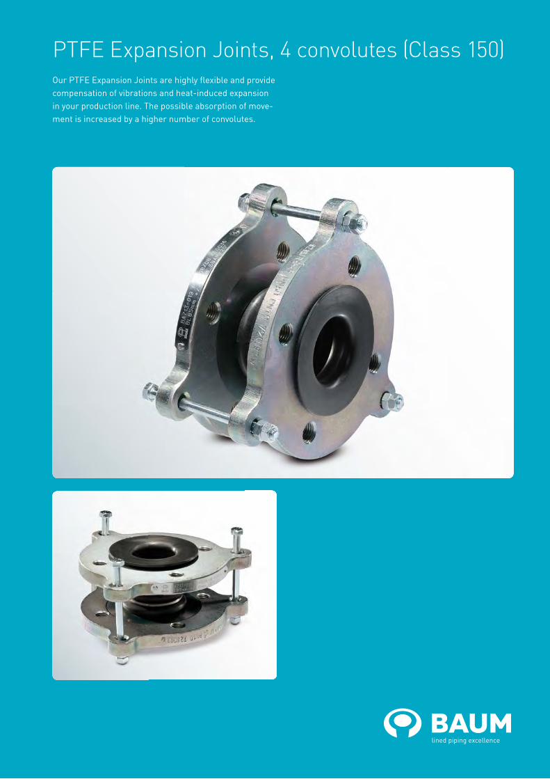
PTFE Expansion Joints, 4 convolutes (Class 150)Our PTFE Expansion Joints are highly flexible and provide compensation of vibrations and heat-induced expansion in your production line. The possible absorption of move-ment is increased by a higher number of convolutes.

baum-lined-piping.comEnglish version BAUM catalogue ANSI-EJ4-2018
PTFE Expansion Joints, 4 convolutes (Class 150) – new designDesigns:• up to nominal pipe size NPS 4“ with two ears• from nominal pipe size NPS 5“ with three ears• up to nominal pipe size NPS 2 1/2” with threaded holes• from nominal pipe size NPS 3” with through holesFlange materials:• carbon steel• stainless steelLining material:• PTFE (virgin or conductive)
Flanges:• loose-looseOther pressure ratings: • on requestSpecial features: • limit bolts/hole extensions• earthing stud/lugOptional extras: • final painting
NPS Overpressure resistance (105 Pa) at
Vacuum resistance(105 Pa) at
23° C 100° C 150° C 200° C 23° C 100° C 150° C 200° C
½“ 10.0 7.4 5.1 3.0 -1.00 -1.00 -1.00 -1.00
¾“ 10.0 7.4 5.1 3.0 -1.00 -1.00 -1.00 -1.00
1“ 10.0 7.4 5.1 3.0 -1.00 -1.00 -1.00 -1.00
1¼“ 10.0 7.4 5.1 3.0 -1.00 -1.00 -1.00 -1.00
1½“ 10.0 7.4 5.1 3.0 -1.00 -1.00 -1.00 -1.00
2“ 10.0 7.4 5.1 3.0 -1.00 -1.00 -1.00 -1.00
2½“ 8.5 6.9 5.1 3.0 -1.00 -0.99 -0.98 -0.96
3“ 8.0 6.6 4.9 2.9 -0.97 -0.96 -0.94 -0.93
4“ 7.4 6.2 4.6 2.7 -0.96 -0.92 -0.89 -0.86
5“ 6.8 5.7 4.3 2.5 -0.93 -0.88 -0.82 -0.77
6“ 6.1 5.2 4.0 2.2 -0.91 -0.84 -0.77 -0.68
8“ 5.1 4.5 3.4 1.8 -0.86 -0.77 -0.66 -0.54
10“ 4.1 3.8 2.8 1.5 -0.81 -0.69 -0.56 -0.40
12“ 3.3 3.0 2.4 1.1 -0.76 -0.62 -0.48 -0.28
L = Total lengthd4 = Raised face diameterK = Bolt circle diametersmin = Minimum flare thicknessa2 = Minimum length with loose flange and smin
Technical data valid for the pressure rating Class 150. a2 depends on construction type and lining thickness.
The overpressure resistance is only valid at neutral position of the PTFE Expansion Joint with limit bolts in place. The types of travel stroke, lateral offset and angular offset are maximum allowable movements in only one direction. For superpositioned movement the single types of travel need to be limited. The figures stated are average and apply to room temperature.
Different nominal pipe sizes and total lengths on request.
NPS L
(mm)
Stroke ±
(mm)
Lateraloffset
(mm)
Angular offset
max. (°)
d4
(mm)
K
(mm)
smin
(mm)
a2
(mm)
No. of bolts
x
thread (UNC)
Weights
(ca. kg/pc.)
½“ 85 13 6 8 34.9 60.3 3.0 13.0 4 x ½“ 1.1
¾“ 85 13 6 8 42.9 69.9 3.0 13.0 4 x ½“ 1.3
1“ 85 13 6 8 50.8 79.4 3.0 13.0 4 x ½“ 1.6
1¼“ 90 13 6 8 63.5 88.9 3.0 13.0 4 x ½“ 1.8
1½“ 98 18 6 8 73.0 98.4 3.0 13.0 4 x ½“ 2.1
2“ 105 20 10 9 92.1 120.7 4.0 16.0 4 x ⅝“ 3.4
2½“ 122 25 10 10 104.8 139.7 4.0 16.0 4 x ⅝“ 4.3
3“ 135 26 12 11 127.0 152.4 4.0 16.0 4 x ⅝“ 5.2
4“ 137 33 15 13 157.2 190.5 5.0 20.0 8 x ⅝“ 8.2
5“ 145 33 15 13 185.7 215.9 4.5 19.5 8 x ¾“ 10.5
6“ 155 33 15 12 215.9 241.3 5.0 23.0 8 x ¾“ 13.6
8“ 175 40 18 10 269.9 298.5 5.0 25.0 8 x ¾“ 22.2
10“ 195 40 18 10 323.8 362.0 7.5 29.5 12 x ⅞“ 30.7
12“ 215 45 18 9 381.0 431.8 6.0 31.0 12 x ⅞“ 51.7
14“ 235 50 22 8 412.8 476.3 7.5 37.5 12 x 1“ 70.0
16“ 235 50 22 8 469.9 539.8 7.5 37.5 16 x 1“ 84.7
20“ 235 50 22 6 584.2 635.0 8.0 38.0 20 x 1⅛“ 102.2

PTFE Expansion Joints, 5 convolutes (Class 150)Our PTFE Expansion Joints are highly flexible and provide compensation of vibrations and heat-induced expansion in your production line. PTFE Expansion Joints with 5 convolutes allow the maximum absorption of movement.

baum-lined-piping.comEnglish version BAUM catalogue ANSI-EJ5-2018
PTFE Expansion Joints, 5 convolutes (Class 150)Flange materials:• carbon steel• stainless steelLining materials:• PTFE (virgin or conductive)
Flanges:• loose-looseOther pressure ratings: • on request
Special features: • limit bolts/hole extensions• earthing stud/lugOptional extras: • final painting
L = Total lengthd4 = Raised face diameterK = Bolt circle diametersmin = Minimum flare thicknessa2 = Minimum length with loose flange and smin
Technical data valid for the pressure rating Class 150. a2 depends on construction type and lining thickness.
The above shown diagram is only valid at neutral position of the PTFE Expansion Joint with limit bolts in place. The types of travel stroke. lateral offset and angular offset are maximum allowable movements in only one direction. For superpositioned movement the single types of travel need to be limited. The figures stated are average and apply to room temperature.
Different nominal pipe sizes and total lengths on request.
NPS L
(mm)
stroke ±
(mm)
lateral offset
(mm)
angular offset
max. (°)
Vacuum resistanceat
d4
(mm)
K
(mm)
smin
(mm)
a2
(mm)
No. of bolts
x
thread (UNC)
Weights
(ca. kg/pc.)
(105 Pa)
max. (°C)
(105 Pa)
max. (°C)
½“ 55 8 5 20
Please confer with us.
34.9 60.3 3.0 11.0 4 x ½“ 1.0
¾“ 55 8 5 20 42.9 69.9 3.0 11.0 4 x ½“ 1.3
1“ 68 8 12 20 50.8 79.4 3.0 11.0 4 x ½“ 1.5
1¼“ 68 8 12 20 63.5 88.9 3.0 13.0 4 x ½“ 2.0
1½“ 80 13 12 20 73.0 98.4 3.0 13.0 4 x ½“ 2.3
2“ 88 19 12 20 92.1 120.7 4.0 16.0 4 x ⅝“ 3.8
2½“ 113 25 13 20 104.8 139.7 4.0 16.0 4 x ⅝“ 5.2
3“ 113 25 16 20 127.0 152.4 4.0 16.0 4 x ⅝“ 5.9
4“ 139 25 16 20 157.2 190.5 5.0 20.0 8 x ⅝“ 9.4
5“ 167 32 16 20 185.7 215.9 4.5 19.5 8 x ¾“ 11.3
6“ 153 32 16 20 215.9 241.3 5.0 23.0 8 x ¾“ 14.9
8“ 207 32 16 20 269.9 298.5 5.0 25.0 8 x ¾“ 24.2
10“ 300 32 16 20 323.8 362.0 7.5 29.5 12 x ⅞“ 35.4
12“ 288 35 18 20 381.0 431.8 6.0 31.0 12 x ⅞“ 56.9
14“ 325 35 18 20 412.8 476.3 7.5 32.5 12 x 1“ 73.1
16“ 343 40 25 20 469.9 539.8 7.5 32.5 16 x 1“ 70.2
18“ 470 40 25 20 533.4 577.9 8.0 33.0 16 x 1⅛“ 89.9
20“ 520 40 25 20 584.2 635.0 8.0 33.0 20 x 1⅛“ 96.7
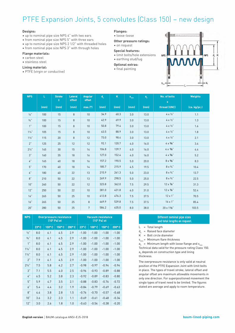
baum-lined-piping.comEnglish version BAUM catalogue ANSI-EJ5-2018
PTFE Expansion Joints, 5 convolutes (Class 150) – new designDesigns:• up to nominal pipe size NPS 4“ with two ears• from nominal pipe size NPS 5“ with three ears• up to nominal pipe size NPS 2 1/2” with threaded holes• from nominal pipe size NPS 3” with through holesFlange materials:• carbon steel• stainless steelLining material:• PTFE (virgin or conductive)
NPS Overpressure resistance (105 Pa) at
Vacuum resistance(105 Pa) at
23° C 100° C 150° C 200° C 23° C 100° C 150° C 200° C
½“ 8.0 6.1 4.5 2.9 -1.00 -1.00 -1.00 -1.00
¾“ 8.0 6.1 4.5 2.9 -1.00 -1.00 -1.00 -1.00
1“ 8.0 6.1 4.5 2.9 -1.00 -1.00 -1.00 -1.00
1¼“ 8.0 6.1 4.5 2.9 -1.00 -1.00 -1.00 -1.00
1½“ 8.0 6.1 4.5 2.9 -1.00 -1.00 -1.00 -1.00
2“ 7.9 6.1 4.5 2.9 -1.00 -1.00 -1.00 -1.00
2½“ 7.5 5.8 4.2 2.7 -0.98 -0.97 -0.94 -0.94
3“ 7.1 5.5 4.0 2.5 -0.96 -0.93 -0.89 -0.88
4“ 6.5 5.2 3.8 2.3 -0.92 -0.89 -0.83 -0.80
5“ 5.9 4.7 3.5 2.1 -0.88 -0.83 -0.76 -0.72
6“ 5.4 4.4 3.2 1.9 -0.84 -0.79 -0.69 -0.63
8“ 4.4 3.8 2.8 1.5 -0.76 -0.70 -0.57 -0.48
10“ 3.6 3.2 2.3 1.1 -0.69 -0.61 -0.48 -0.34
12“ 3.0 2.6 1.8 1.0 -0.63 -0.54 -0.38 -0.20
Flanges:• loose-looseOther pressure ratings: • on requestSpecial features: • limit bolts/hole extensions• earthing stud/lugOptional extras: • final painting
L = Total lengthd4 = Raised face diameterK = Bolt circle diametersmin = Minimum flare thicknessa2 = Minimum length with loose flange and smin
Technical data valid for the pressure rating Class 150. a2 depends on construction type and lining thickness.
The overpressure resistance is only valid at neutral position of the PTFE Expansion Joint with limit bolts in place. The types of travel stroke, lateral offset and angular offset are maximum allowable movements in only one direction. For superpositioned movement the single types of travel need to be limited. The figures stated are average and apply to room temperature.
Different nominal pipe sizes and total lengths on request.
NPS L
(mm)
Stroke ±
(mm)
Lateraloffset
(mm)
Angular offset
max. (°)
d4
(mm)
K
(mm)
smin
(mm)
a2
(mm)
No. of bolts
x
thread (UNC)
Weights
(ca. kg/pc.)
½“ 100 15 8 10 34.9 60.3 3.0 13.0 4 x ½“ 1.1
¾“ 100 15 8 10 42.9 69.9 3.0 13.0 4 x ½“ 1.3
1“ 100 15 8 10 50.8 79.4 3.0 13.0 4 x ½“ 1.6
1¼“ 105 15 8 10 63.5 88.9 3.0 13.0 4 x ½“ 1.8
1½“ 115 20 8 12 73.0 98.4 3.0 13.0 4 x ½“ 2.1
2“ 125 25 12 12 92.1 120.7 4.0 16.0 4 x ⅝“ 3.4
2½“ 145 30 15 14 104.8 139.7 4.0 16.0 4 x ⅝“ 4.4
3“ 160 35 18 16 127.0 152.4 4.0 16.0 4 x ⅝“ 5.2
4“ 165 40 18 16 157.2 190.5 5.0 20.0 8 x ⅝“ 8.3
5“ 170 40 18 14 185.7 215.9 4.5 19.5 8 x ¾“ 10.4
6“ 180 40 22 13 215.9 241.3 5.0 23.0 8 x ¾“ 13.7
8“ 210 50 22 13 269.9 298.5 5.0 25.0 8 x ¾“ 22.5
10“ 240 50 22 12 323.8 362.0 7.5 29.5 12 x ⅞“ 31.3
12“ 250 50 22 10 381.0 431.8 6.0 31.0 12 x ⅞“ 52.4
14“ 265 50 25 10 412.8 476.3 7.5 37.5 12 x 1“ 70.5
16“ 265 50 25 8 469.9 539.8 7.5 37.5 16 x 1“ 85.4
20“ 280 50 25 7 584.2 635.0 8.0 38.0 20 x 1⅛“ 103.5
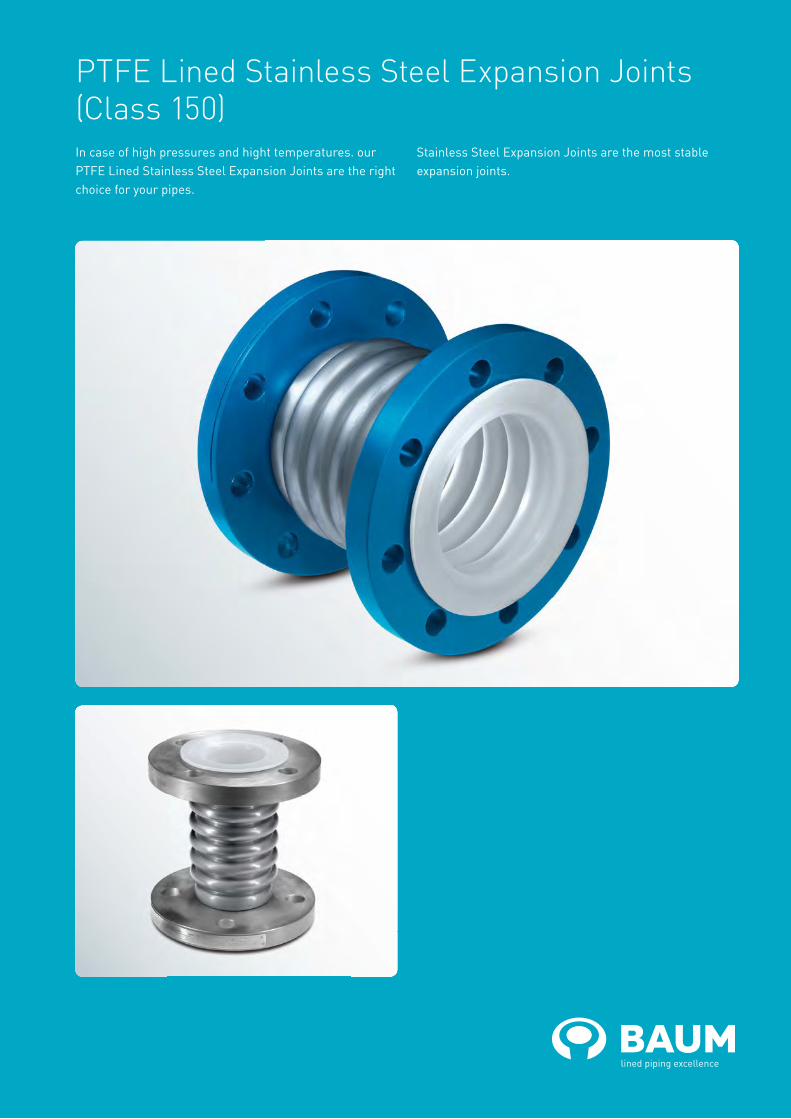
PTFE Lined Stainless Steel Expansion Joints (Class 150)In case of high pressures and hight temperatures. our PTFE Lined Stainless Steel Expansion Joints are the right choice for your pipes.
Stainless Steel Expansion Joints are the most stable expansion joints.

baum-lined-piping.comEnglish version BAUM catalogue ANSI-EJS-2018
PTFE Lined Stainless Steel Expansion Joints (Class 150)Flange materials:• carbon steel• stainless steelLining material:• PTFE (virgin or conductive)Bellow material:• stainless steel
Flanges:• loose-looseOther pressure rating: • Class 300 Special features: • earthing stud/lugOptional extras: • final painting (flanges)
L = Total lengthd4 = Raised face diameterTechnical data valid for the pressure rating Class 150.
Different nominal pipe sizes and total lengths on request.
NPS L
(mm)
Stroke±
(mm)
Axialspring rate
(N/mm)
Vacuum resistance (105 Pa) at
d4
(mm)
No. of bolts
x
thread (UNC)
Weights
(ca. kg/pc.)23° C 160° C
1¼“ 145 4.5 260 0.15 0.30 63.5 4 x ½“ 4.0
1¼“ 220 9.0 130 0.15 0.30 63.5 4 x ½“ 4.0
1½“ 155 5.5 272 0.15 0.30 73.0 4 x ½“ 5.0
1½“ 240 11.0 136 0.15 0.30 73.0 4 x ½“ 5.0
2“ 177 6.5 276 0.15 0.30 92.1 4 x ⅝“ 6.0
2“ 292 13.5 195 0.15 0.30 92.1 4 x ⅝“ 6.0
2½“ 179 8.5 234 0.15 0.30 104.8 4 x ⅝“ 7.0
2½“ 285 16.0 173 0.15 0.30 104.8 4 x ⅝“ 7.5
3“ 183 10.0 220 0.15 0.30 127.0 4 x ⅝“ 7.5
3“ 273 17.5 178 0.15 0.30 127.0 4 x ⅝“ 8.5
4“ 178 10.0 365 0.15 0.30 157.2 8 x ⅝“ 10.0
4“ 266 20.0 183 0.15 0.30 157.2 8 x ⅝“ 11.5
5“ 221 14.5 290 0.25 0.40 185.7 8 x ¾“ 13.0
5“ 363 25.0 290 0.25 0.40 185.7 8 x ¾“ 15.0
6“ 248 15.0 560 0.25 0.40 215.9 8 x ¾“ 17.0
6“ 388 30.0 280 0.25 0.40 215.9 8 x ¾“ 20.0
8“ 246 21.0 412 0.35 0.50 269.9 8 x ¾“ 24.0
8“ 418 39.0 335 0.35 0.50 269.9 8 x ¾“ 30.0
10“ 243 22.0 525 0.40 0.60 323.8 12 x ⅞“ 32.0
10“ 392 40.5 269 0.40 0.60 323.8 12 x ⅞“ 35.0
12“ 287 27.5 480 0.50 0.75 381.0 12 x ⅞“ 37.0
12“ 429 47.5 352 0.50 0.75 381.0 12 x ⅞“ 43.0
14“ 296 30.0 460 0.50 0.75 412.8 12 x 1“ 51.0
14“ 407 46.0 378 0.50 0.75 412.8 12 x 1“ 57.0
16“ 290 26.0 713 0.70 0.90 469.9 16 x 1“ 68.0
16“ 434 52.0 357 0.70 0.90 469.9 16 x 1“ 75.0
18“ 328 35.0 548 0.70 0.90 533.4 16 x 1⅛“ 76.0
18“ 535 65.0 430 0.70 0.90 533.4 16 x 1⅛“ 97.0
20“ 309 28.0 955 - - 584.2 20 x 1⅛“ 97.0
20“ 509 63.0 425 - - 584.2 20 x 1⅛“ 113.0
24“ 336 35.0 548 - - 692.2 20 x 1¼“ 118.0
24“ 484 63.0 305 - - 692.2 20 x 1¼“ 130.0

PTFE Vacuum Expansion Joints (Class 150)PTFE Vacuum Expansion Joints allow full vacuum, also in case of large nominal widths and high temperatures.

baum-lined-piping.comEnglish version BAUM catalogue ANSI-EJV-2018
PTFE Vacuum Expansion Joints (Class 150)Flange materials:• carbon steel• stainless steelLining material:• PTFE (virgin or conductive)Flanges:• loose-loose
Other pressure ratings: • on requestSpecial features: • limit bolts/hole extensions• earthing stud/lugOptional extras: • final painting
NPS Overpressure resistance(105 Pa) at
Vacuum resistance(105 Pa) at
23° C 200° C 200° C
4“ 3.0 3.0 -1.0
6“ 3.0 3.0 -1.0
6“ 3.0 3.0 -1.0
8“ 3.0 3.0 -1.0
10“ 3.0 3.0 -1.0
12“ 3.0 3.0 -1.0
14“ 3.0 1.0 -1.0
16“ 3.0 1.0 -1.0
18“ 3.0 1.0 -1.0
L = Total lengthD = Outer diameterd4 = Raised face diameterK = Bolt circle diametersmin = Minimum flare thicknessa2 = Minimum length with loose flange and smin
Technical data valid for the pressure rating Class 150. a2 depends on construction type and lining thickness.
The overpressure resistance is only valid at neutral position of the PTFE Vacuum Expansion Joint. The figures stated are average and apply to room temperature.
Different nominal pipe sizes and total lengths on request.
NPS L
(mm)
Stroke±
(mm)
D
(mm)
d4
(mm)
K
(mm)
smin
(mm)
a2
(mm)
No. of bolts
x
thread (UNC)
Weights
(ca. kg/pc.)
4“ 95 10 302 157.2 190.5 7.5 23.5 8 x ⅝“ 15.7
6“ 100 15 350 215.9 241.3 7.5 25.5 8 x ¾“ 20.0
8“ 105 15 422 269.9 298.5 7.5 27.5 8 x ¾“ 29.7
10“ 110 18 476 323.8 362.0 7.5 29.5 12 x ⅞“ 37.6
12“ 115 18 535 381.0 431.8 7.5 32.5 12 x ⅞“ 57.4
14“ 120 18 590 412.8 476.3 7.5 32.5 12 x 1“ 66.8
16“ 135 20 670 469.9 539.8 7.5 32.5 16 x 1“ 76.8
18“ 150 20 745 533.4 577.9 7.5 32.5 16 x 1⅛“ 82.2
20“ 160 20 770 584.2 635.0 8.0 33.0 20 x 1⅛“ 91.8

baum-lined-piping.com
PTFE Vacuum Expansion Joints (Class 150) – new designDesigns:• up to nominal pipe size NPS 4“ with two ears• from nominal pipe size NPS 5“ with three ears• up to nominal pipe size NPS 2 1/2” with threaded holes• from nominal pipe size NPS 3” with through holesFlange materials:• carbon steel• stainless steel
Lining material:• PTFE (virgin or conductive)Flanges: • loose-looseOther pressure ratings: • on requestSpecial features: • limit bolts/hole extensions• earthing stud/lugOptional extras: • final painting
NPS Overpressure resistance(105 Pa) at
Vacuum resistance(105 Pa) at
23° C 200° C 200° C
4“ 3.0 3.0 -1.0
5“ 3.0 3.0 -1.0
6“ 3.0 3.0 -1.0
8“ 3.0 3.0 -1.0
10“ 3.0 3.0 -1.0
12“ 3.0 3.0 -1.0
14“ 3.0 3.0 -1.0
16“ 3.0 1.0 -1.0
18“ 3.0 1.0 -1.0
20“ 3.0 1.0 -1.0
24“ 3.0 1.0 -1.0
28“ 1.0 0.5 -1.0
32“ 0.5 0.3 -1.0
36“ 0.1 0.1 -1.0
40“ 0.0 0.0 -1.0
English version BAUM catalogue ANSI-EJV-2018
L = Total lengthd4 = Raised face diameterK = Bolt circle diametersmin = Minimum flare thickness
Technical data valid for the pressure rating Class 150. a2 depends on construction type and lining thickness.
The overpressure resistance is only valid at neutral position of the PTFE Vacuum Expansion Joint with limit bolts in place. The types of travel stroke, lateral offset and angular offset are maximum allowable movements in only one direction. For superpositioned movement the single types of travel need to be limit-ed. The figures stated are average and apply to room temperature.
Different nominal pipe sizes and total lengths on request.
NPS L
(mm)
Stroke±
(mm)
Lateral offset
(mm)
Angular offset
(mm)
d4
(mm)
K
(mm)
smin
(mm)
a2
(mm)
No. of bolts
x
thread (UNC)
Weights
(ca. kg/pc.)
4“ 150 12 3 4 157.2 190.5 7.5 22.5 8 x ⅝“ 19.9
5“ 150 12 4 4 185.7 215.9 7.5 22.5 8 x ¾“ 24.9
6“ 150 12 4 4 215.9 241.3 7.5 25.5 8 x ¾“ 28.8
8“ 150 15 5 4 269.9 298.5 7.5 27.5 8 x ¾“ 44.7
10“ 150 15 6 4 323.8 362.0 7.5 29.5 12 x ⅞“ 56.6
12“ 150 20 7 4 381.0 431.8 7.5 32.5 12 x ⅞“ 91.4
14“ 160 20 7 4 412.8 476.3 7.5 37.5 12 x 1“ 117.2
16“ 160 20 8 3 469.9 539.8 7.5 37.5 16 x 1“ 126.7
20“ 160 20 9 3 584.2 635.0 8.0 38.0 20 x 1⅛“ 130.1
24“ 170
Please determine the desired standard - ASME B 16.47 Series A/B or British Standard 3293 - when contacting our sales department.
28“ 170
32“ 170
36“ 170
40“ 170

Spectacle Blinds
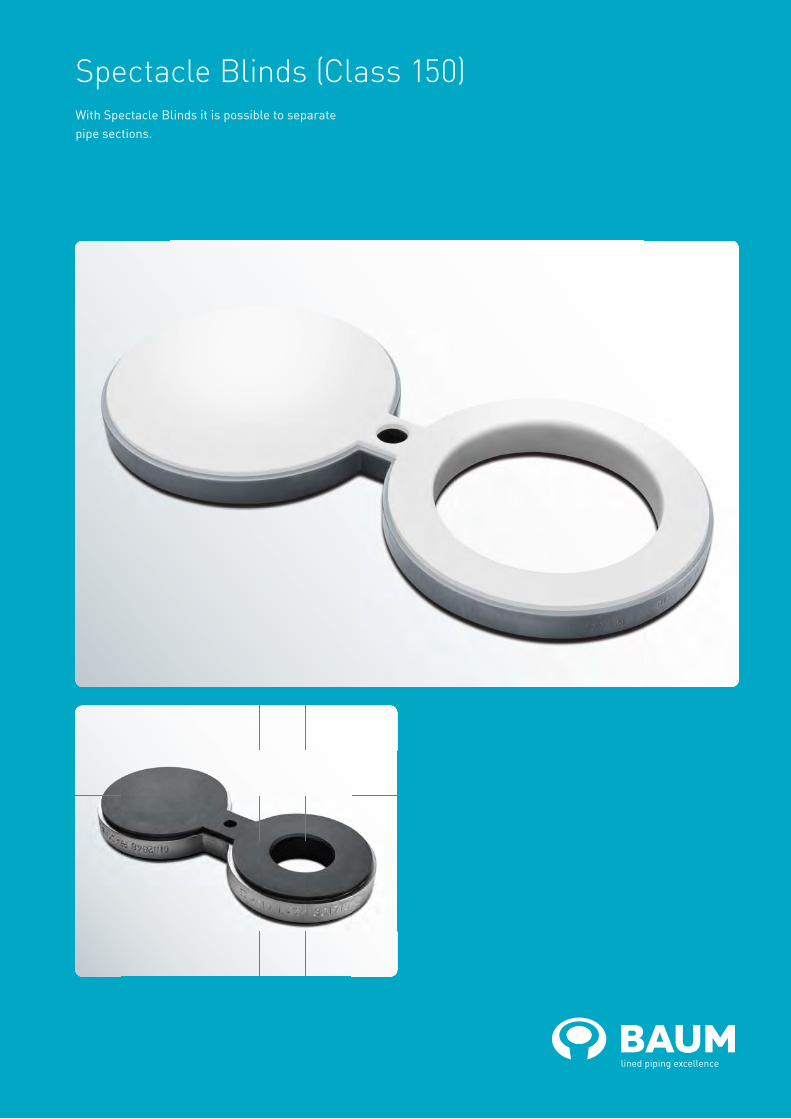
Spectacle Blinds (Class 150)With Spectacle Blinds it is possible to separate pipe sections.

baum-lined-piping.comEnglish version BAUM catalogue ANSI-BS-2018
Spectacle Blinds (Class 150)Materials:• carbon steel• stainless steelLining material:• PFA (virgin or conductive)Other pressure rating:• Class 300
NPSLining thickness Possible vacuum
standard thick-walled 23° C 150° C 200° C
1“
1½“
2“
3“
4“
6“
8“
10“
12“
L = Total length Bmin = Minimum thicknessd2 = Inner diameterd4 = Raised face diameterd8 = Outer diameters = Lining thicknessF = Distance of the circle centersI = Quick-release axle diameterTechnical data valid for the pressure rating Class 150. B depend on construction typeand lining thickness.
Special features: • earthing stud/lugOptional extras: • final painting
Different nominal pipe sizesand total lengths on request.
Vacuum resistance: = full vacuum = limited vacuum = no vacuum
Please refer to the next higher nominal pipe size if your nominal pipe size is not listed.
NPS L
(mm)
Bmin
(mm)
d2
(mm)
d4
(mm)
d8
(mm)
s
(mm)
F
(mm)
I
(mm)
Weights
(ca. kg/pc.)
½“ 100.5 17.2 14.9 34.9 40 4.0 60.5 15.7 0.3
¾“ 117.9 18.7 14.9 42.9 48 4.0 69.9 15.7 0.4
1“ 134.2 20.2 20.6 50.8 55 4.0 79.2 15.7 0.6
1¼“ 156.9 21.7 29.0 63.5 68 4.0 88.9 15.7 0.9
1½“ 173.6 23.7 34.9 73.0 75 4.0 98.6 15.7 1.3
2“ 215.7 25.1 46.5 92.1 95 4.0 120.7 19.1 2.2
2½“ 247.7 28.4 56.6 104.8 108 4.0 139.7 19.1 3.2
3“ 282.3 29.9 71.9 127.0 130 4.0 152.3 19.1 4.6
4“ 350.5 29.9 96.3 157.2 160 4.0 190.5 19.1 6.8
5“ 405.9 29.9 122.1 185.7 190 4.0 215.9 22.4 9.2
6“ 459.3 31.4 148.1 215.9 218 4.0 241.3 22.4 12.4
8“ 572.5 34.4 196.7 269.9 274 4.0 298.5 22.4 21.0
10“ 690.0 36.2 248.4 323.8 328 4.0 362.0 25.4 30.6
12“ 816.8 37.8 298.8 381.0 385 4.0 431.8 25.4 43.5

Nozzle Liners / Dip Pipes
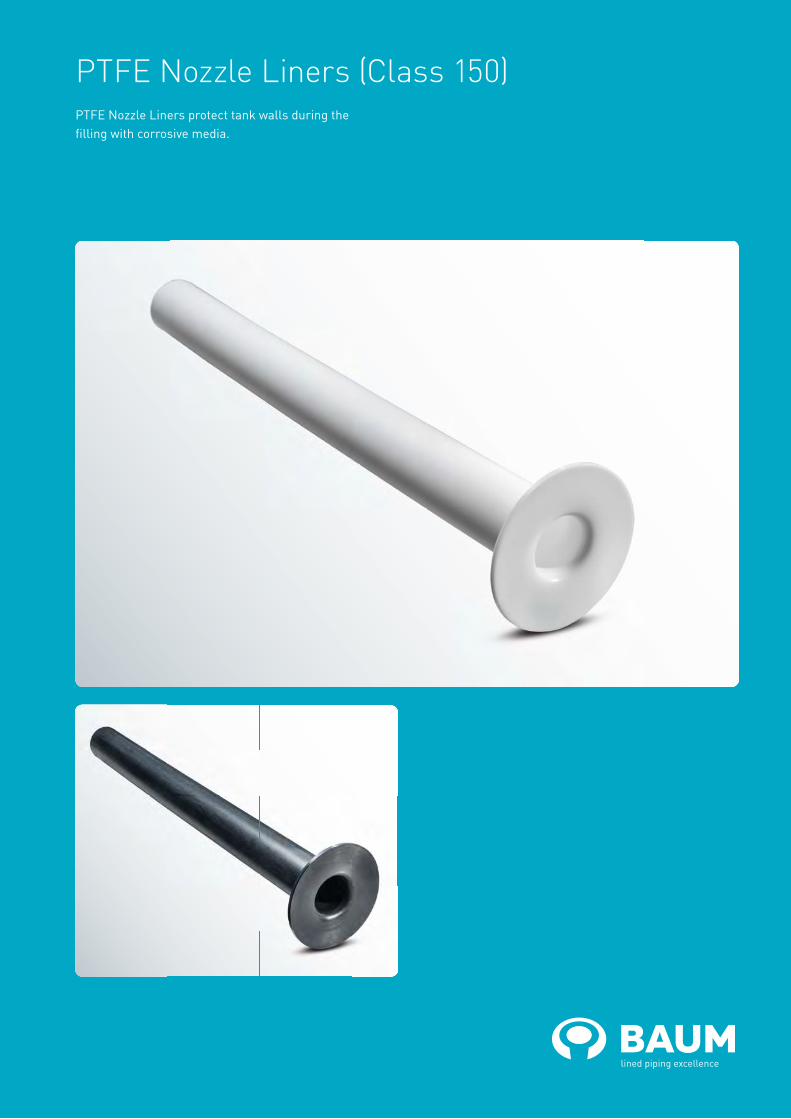
PTFE Nozzle Liners (Class 150)PTFE Nozzle Liners protect tank walls during the filling with corrosive media.

baum-lined-piping.comEnglish version BAUM catalogue ANSI-NL-2018
PTFE Nozzle Liners (Class 150)Material:• PTFE (virgin or conductive)
Lmax = Maximum total lengthd1 = Outer diameter of the piped4 = Raised face diameters = Lining thicknessTechnical data valid for the pressure rating Class 150.
Different outer diameters of the pipe and raised face diameters on request.
NPS Lmax
(mm)
d1
(mm)
d4
(mm)
s
(mm)
Tolerancefor d1
± (mm)
Weights
(ca. kg/m)
1“ 6000 19 50.8 3.0 2 0.3
1¼“ 6000 27 63.5 3.0 2 0.5
1½“ 6000 32 73.0 4.0 2 0.8
2“ 6000 43 92.1 4.0 3 1.1
2½“ 6000 51 104.8 4.0 4 1.3
3“ 6000 66 127.0 4.0 4 1.7
4“ 6000 89 157.2 4.0 5 2.3
5“ 6000 114 185.7 4.5 5 3.3
6“ 6000 139 215.9 4.5 5 4.1
8“ 6000 182 269.9 5.0 6 6.0
10“ 4000 225 323.8 5.0 10 7.4
12“ 4000 283 381.0 5.0 10 9.4
14“ 4000 316 412.8 5.0 10 10.5
16“ 4000 363 469.9 7.5 10 18.0
20“ 2000 468 584.2 8.0 10 24.9

PTFE-lined Dip Pipes (Class 150)PTFE-lined Dip Pipes allow the precise feeding of corrosive media into tanks. Nozzle heads additionally offer the possibility of a directed dispersion of operating media.
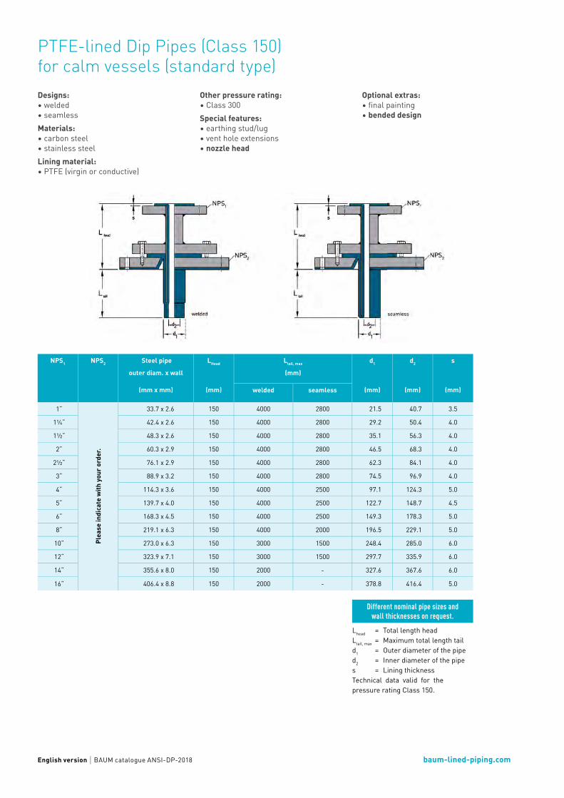
baum-lined-piping.comEnglish version BAUM catalogue ANSI-DP-2018
PTFE-lined Dip Pipes (Class 150) for calm vessels (standard type)Designs:• welded• seamlessMaterials:• carbon steel• stainless steelLining material:• PTFE (virgin or conductive)
Other pressure rating:• Class 300Special features: • earthing stud/lug• vent hole extensions• nozzle head
Lhead = Total length headLtail, max = Maximum total length taild1 = Outer diameter of the pipe d2 = Inner diameter of the pipes = Lining thickness Technical data valid for the pressure rating Class 150.
Optional extras: • final painting• bended design
Different nominal pipe sizes and wall thicknesses on request.
NPS1 NPS2 Steel pipe
outer diam. x wall
(mm x mm)
LHead
(mm)
Ltail, max
(mm)
d1
(mm)
d2
(mm)
s
(mm)welded seamless
1“
Plea
se in
dica
te w
ith y
our o
rder
.
33.7 x 2.6 150 4000 2800 21.5 40.7 3.5
1¼“ 42.4 x 2.6 150 4000 2800 29.2 50.4 4.0
1½“ 48.3 x 2.6 150 4000 2800 35.1 56.3 4.0
2“ 60.3 x 2.9 150 4000 2800 46.5 68.3 4.0
2½“ 76.1 x 2.9 150 4000 2800 62.3 84.1 4.0
3“ 88.9 x 3.2 150 4000 2800 74.5 96.9 4.0
4“ 114.3 x 3.6 150 4000 2500 97.1 124.3 5.0
5“ 139.7 x 4.0 150 4000 2500 122.7 148.7 4.5
6“ 168.3 x 4.5 150 4000 2500 149.3 178.3 5.0
8“ 219.1 x 6.3 150 4000 2000 196.5 229.1 5.0
10“ 273.0 x 6.3 150 3000 1500 248.4 285.0 6.0
12“ 323.9 x 7.1 150 3000 1500 297.7 335.9 6.0
14“ 355.6 x 8.0 150 2000 - 327.6 367.6 6.0
16“ 406.4 x 8.8 150 2000 - 378.8 416.4 5.0
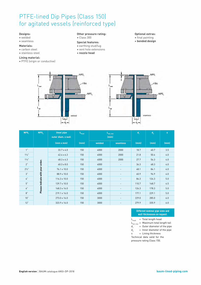
baum-lined-piping.comEnglish version BAUM catalogue ANSI-DP-2018
PTFE-lined Dip Pipes (Class 150) for agitated vessels (reinforced type)
Lhead = Total length headLtail, max = Maximum total length taild1 = Outer diameter of the pipe d2 = Inner diameter of the pipes = Lining thickness Technical data valid for the pressure rating Class 150.
Different nominal pipe sizes and wall thicknesses on request.
NPS1 NPS2 Steel pipe
outer diam. x wall
(mm x mm)
LHead
(mm)
Ltail, max
(mm)
d1
(mm)
d2
(mm)
s
(mm)welded seamless
1“
Plea
se in
dica
te w
ith y
our o
rder
.
33.7 x 4.0 150 4000 2000 18.7 40.7 3.5
1¼“ 42.4 x 6.3 150 4000 2000 21.8 50.4 4.0
1½“ 48.3 x 6.3 150 4000 2000 27.7 56.3 4.0
2“ 60.3 x 8.0 150 4000 - 36.3 68.3 4.0
2½“ 76.1 x 10.0 150 4000 - 48.1 84.1 4.0
3“ 88.9 x 10.0 150 4000 - 60.9 96.9 4.0
4“ 114.3 x 10.0 150 4000 - 84.3 124.3 5.0
5“ 139.7 x 10.0 150 4000 - 110.7 148.7 4.5
6“ 168.3 x 16.0 150 4000 - 126.3 178.3 5.0
8“ 219.1 x 16.0 150 4000 - 177.1 229.1 5.0
10“ 273.0 x 16.0 150 3000 - 229.0 285.0 6.0
12“ 323.9 x 16.0 150 3000 - 279.9 335.9 6.0
Designs:• welded• seamlessMaterials:• carbon steel• stainless steelLining material:• PTFE (virgin or conductive)
Other pressure rating:• Class 300Special features: • earthing stud/lug• vent hole extensions• nozzle head
Optional extras: • final painting• bended design

Hoses

PTFE Chemical Transfer Hoses (Class 150) – smooth bore with stripwound houseThe stripwound hose is a metal protection hose with a high mechanical strength, for higher pressures; the hose is torsion-proofed, high tensile and it has a straight PTFE liner.

baum-lined-piping.comEnglish version BAUM catalogue ANSI-H1-2018
PTFE Chemical Transfer Hoses (Class 150) – smooth bore with stripwound houseMaterials Flanges:• carbon steel• stainless steelMaterial Hoses:• stainless steelLining material:• PTFE (virgin or conductive)Flanges:• fix-fix• fix-loose• loose-loose
Other pressure rating:• Class 300Special features: • earthing stud/lug• flange stopper Optional extras: • final painting (flanges)
Detail X
Lmax = Maximum lengthd4 = Raised face diameterd8 = Outer diameterK = Bolt circle diameterTechnical data valid for the pressure rating Class 150.
Different nominal pipe sizes on request.
NPS Lmax
(mm)
Min. bend radius
(mm)
Max.working pressure
(105 Pa)
d4
(mm)
d8
(mm)
K
(mm)
No. of bolts
x
thread (UNC)
Weights
Hose(ca. kg/m)
Flange(ca. kg/side)
½“ 5000 325 10.0 34.9 19 60.3 4 x ½“ 0.5 0.4
¾“ 5000 350 10.0 42.9 23 69.9 4 x ½“ 0.6 0.6
1“ 5000 350 10.0 50.8 28 79.4 4 x ½“ 0.9 0.8
1¼“ 5000 400 10.0 63.5 35 88.9 4 x ½“ 1.1 1.0
1½“ 5000 550 10.0 73.0 45 98.4 4 x ½“ 1.6 1.3
2“ 5000 750 10.0 92.1 55 120.7 4 x ⅝“ 2.0 2.0
3“ 5000 1300 10.0 127.0 87 152.4 4 x ⅝“ 5.0 3.8
4“ 5000 1500 7.5 157.2 100 190.5 8 x ⅝“ 6.8 5.3

PTFE Chemical Transfer Hoses (Class 150) – smooth bore / annularly corrugating / wire braidThe annularly corrugated hose shows a multitude of self-contained and parallel metal convolutes in equal distance. The annularly corrugated hose has a braiding
to increase the pressure resistance. It has a straight PTFE lining.

baum-lined-piping.comEnglish version BAUM catalogue ANSI-H2-2018
PTFE Chemical Transfer Hoses (Class 150) – smooth bore with annularly corrugating and wire braidMaterials Flanges:• carbon steel• stainless steelMaterial Hoses:• stainless steelLining material:• PTFE (virgin or conductive)Flanges:• fix-fix• fix-loose• loose-loose
Other pressure rating:• Class 300Special features: • earthing stud/luge• flange stopper Optional extras: • final painting (flanges)
Lmax = Maximum lengthd4 = Raised face diameterK = Bolt circle diameterTechnical data valid for the pressure rating Class 150.
Different nominal pipe sizes on request.
NPS Lmax
(mm)
Min.bend radius
(mm)
Max.working pressure
(105 Pa)
d4
(mm)
K
(mm)
No. of bolts
x
thread (UNC)
Weights
Hose(ca. kg/m)
Flange(ca. kg/side)
1“ 5000 350 25 50.8 79.4 4 x ½“ 0.8 0.8
1¼“ 5000 400 20 63.5 88.9 4 x ½“ 1.0 1.0
1½“ 5000 550 16 73.0 98.4 4 x ½“ 1.6 1.3
2“ 5000 750 16 92.1 120.7 4 x ⅝“ 1.6 2.0
2½“ 5000 1000 14 104.8 139.7 4 x ⅝“ 1.8 3.3
3“ 5000 1300 12 127.0 152.4 4 x ⅝“ 2.6 3.8
4“ 5000 1500 10 157.2 190.5 8 x ⅝“ 3.5 5.3
5“ 5000 1800 10 185.7 215.9 8 x ¾“ 5.8 6.0
6“ 5000 2000 10 215.9 241.3 8 x ¾“ 8.2 7.4
8“ 5000 2500 10 269.9 298.5 8 x ¾“ 11.0 12.0

PTFE Spiral Hoses (Class 150)The spiral-convoluted PTFE hose offers a high flexibility, but shows a low pressure resistance.
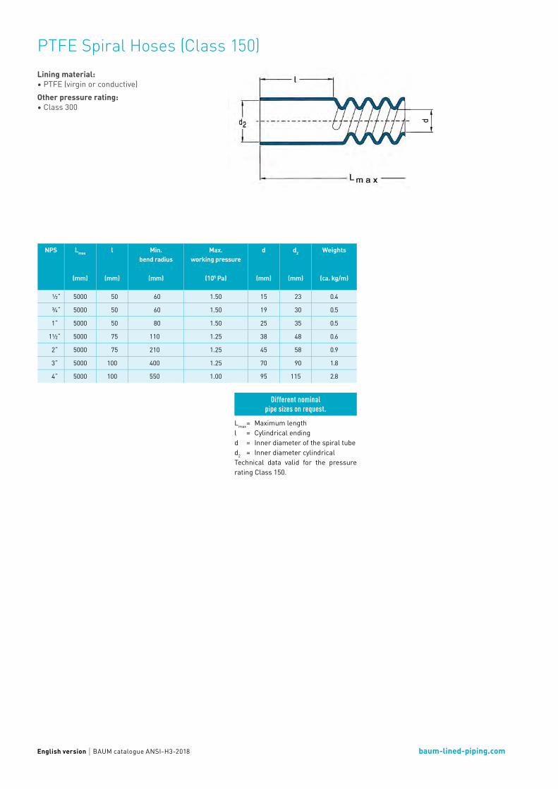
baum-lined-piping.comEnglish version BAUM catalogue ANSI-H3-2018
PTFE Spiral Hoses (Class 150)Lining material:• PTFE (virgin or conductive)Other pressure rating:• Class 300
Lmax = Maximum lengthl = Cylindrical endingd = Inner diameter of the spiral tubed2 = Inner diameter cylindricalTechnical data valid for the pressure rating Class 150.
Different nominal pipe sizes on request.
NPS Lmax
(mm)
l
(mm)
Min.bend radius
(mm)
Max.working pressure
(105 Pa)
d
(mm)
d2
(mm)
Weights
(ca. kg/m)
½“ 5000 50 60 1.50 15 23 0.4
¾“ 5000 50 60 1.50 19 30 0.5
1“ 5000 50 80 1.50 25 35 0.5
1½“ 5000 75 110 1.25 38 48 0.6
2“ 5000 75 210 1.25 45 58 0.9
3“ 5000 100 400 1.25 70 90 1.8
4“ 5000 100 550 1.00 95 115 2.8

PTFE Spiral Hoses (Class 150) with flangesThe spiral-convoluted PTFE hose offers a high flexibility, but shows a low pressure resistance. For connection with PTFE flared flanges.
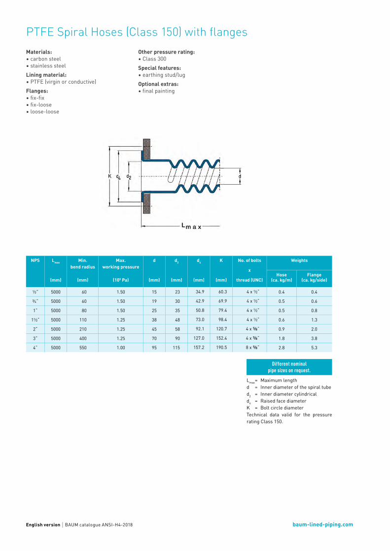
baum-lined-piping.comEnglish version BAUM catalogue ANSI-H4-2018
PTFE Spiral Hoses (Class 150) with flangesMaterials:• carbon steel• stainless steelLining material:• PTFE (virgin or conductive)Flanges:• fix-fix• fix-loose• loose-loose
Other pressure rating:• Class 300Special features: • earthing stud/lugOptional extras: • final painting
Lmax = Maximum lengthd = Inner diameter of the spiral tubed2 = Inner diameter cylindricald4 = Raised face diameterK = Bolt circle diameterTechnical data valid for the pressure rating Class 150.
Different nominal pipe sizes on request.
NPS Lmax
(mm)
Min.bend radius
(mm)
Max.working pressure
(105 Pa)
d
(mm)
d2
(mm)
d4
(mm)
K
(mm)
No. of bolts
x
thread (UNC)
Weights
Hose(ca. kg/m)
Flange(ca. kg/side)
½“ 5000 60 1.50 15 23 34.9 60.3 4 x ½“ 0.4 0.4
¾“ 5000 60 1.50 19 30 42.9 69.9 4 x ½“ 0.5 0.6
1“ 5000 80 1.50 25 35 50.8 79.4 4 x ½“ 0.5 0.8
1½“ 5000 110 1.25 38 48 73.0 98.4 4 x ½“ 0.6 1.3
2“ 5000 210 1.25 45 58 92.1 120.7 4 x ⅝“ 0.9 2.0
3“ 5000 400 1.25 70 90 127.0 152.4 4 x ⅝“ 1.8 3.8
4“ 5000 550 1.00 95 115 157.2 190.5 8 x ⅝“ 2.8 5.3
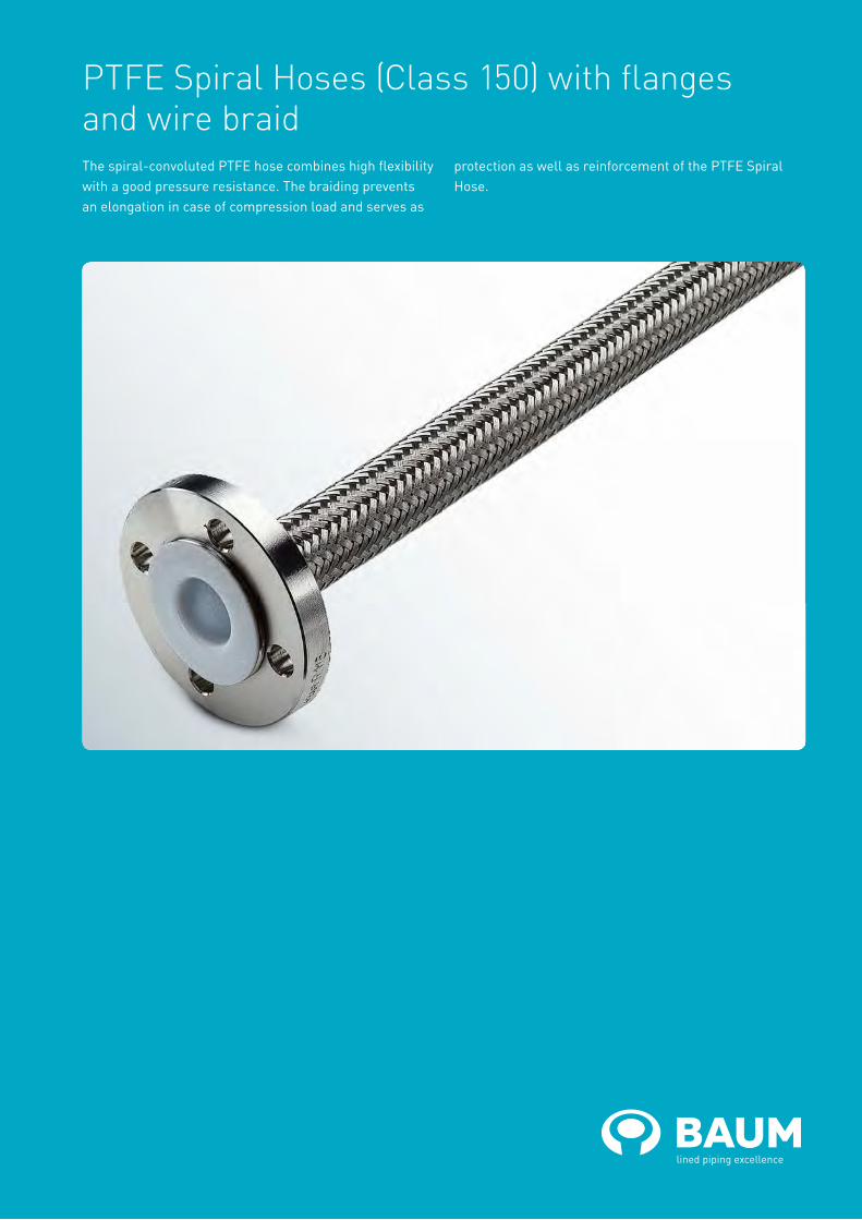
PTFE Spiral Hoses (Class 150) with flanges and wire braidThe spiral-convoluted PTFE hose combines high flexibility with a good pressure resistance. The braiding prevents an elongation in case of compression load and serves as
protection as well as reinforcement of the PTFE Spiral Hose.

baum-lined-piping.comEnglish version BAUM catalogue ANSI-H5-2018
PTFE Spiral Hoses (Class 150) with flanges and wire braidMaterials Flanges:• carbon steel• stainless steelMaterial Hoses:• stainless steelLining material:• PTFE (virgin or conductive)Flanges:• fix-fix• fix-loose• loose-loose
Other pressure rating:• Class 300Special features: • earthing stud/lug• flange stopperOptional extras: • final painting (flanges)
Lmax = Maximum lengthd = Inner diameter of the spriral tubed4 = Raised face diameterK = Bolt circle diameterTechnical data valid for the pressure rating Class 150.
Different nominal pipe sizes on request.
NPS Lmax
(mm)
Min.bend radius
(mm)
Max.working pressure
(105 Pa)
d
(mm)
d4
(mm)
K
(mm)
No. of bolts
x
thread (UNC)
Weights
Hose(ca. kg/m)
Flange(ca. kg/side)
½“ 5000 80 10 15 34.9 60.3 4 x ½“ 0.6 0.4
¾“ 5000 80 10 19 42.9 69.9 4 x ½“ 0.9 0.6
1“ 5000 115 10 25 50.8 79.4 4 x ½“ 1.0 0.8
1½“ 5000 150 10 38 73.0 98.4 4 x ½“ 1.3 1.3
2“ 5000 200 10 45 92.1 120.7 4 x ⅝“ 1.8 2.0
3“ 5000 400 5 70 127.0 152.4 4 x ⅝“ 3.5 3.8
4“ 5000 600 5 95 157.2 190.5 8 x ⅝“ 4.6 5.3
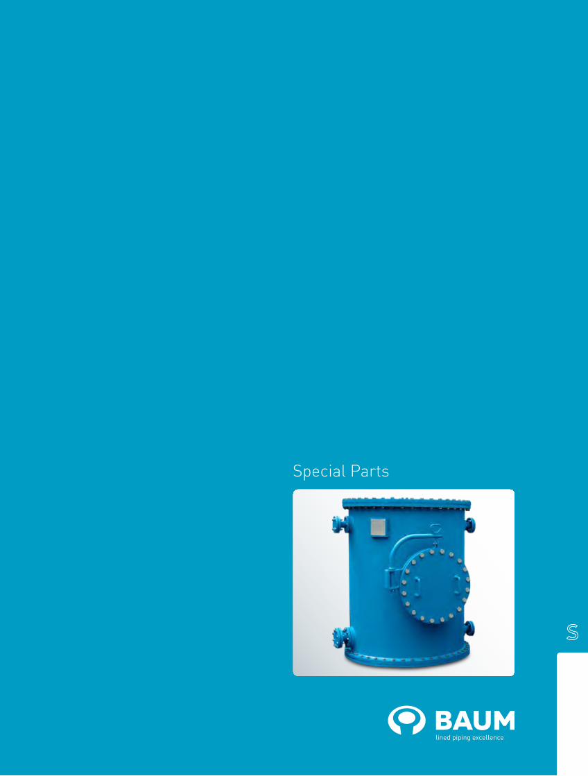
Special Parts

Special partsIf you did not find the piping part you need in this cata-logue, please contact us. We also manufacture special forms or dimensions according to your requirements.
Simply send us your technical drawing or a sketch and we will suggest a possible solution.

baum-lined-piping.comEnglish version BAUM catalogue ANSI-SP-2018
Special parts

Accessories
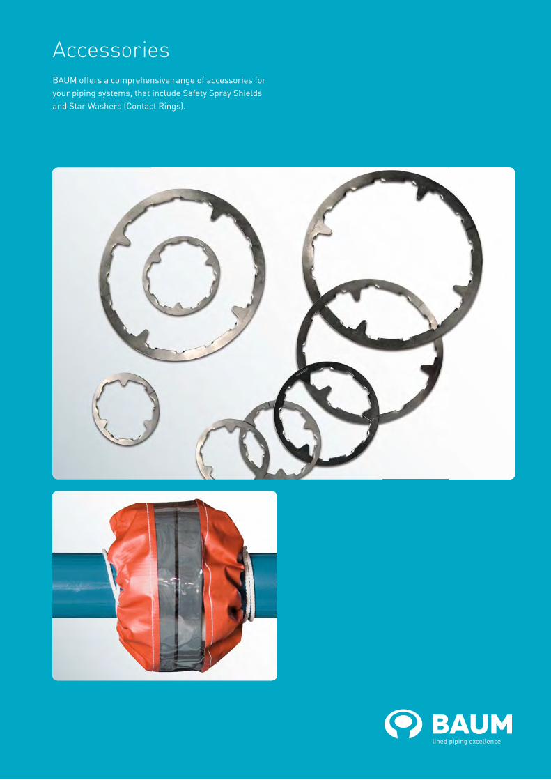
AccessoriesBAUM offers a comprehensive range of accessories for your piping systems, that include Safety Spray Shields and Star Washers (Contact Rings).

baum-lined-piping.comEnglish version BAUM catalogue ANSI-ADD-2018
AccessoriesStar Washer (Contact Rings)Contact Rings ensure electric contact and conductivi-ty between the lap-joint flange and the stub-end, even though the surface of your piping parts have a final painting. Thus secure earthing is possible with protective finishing. The Contact Rings are gripped between lap-joint flange and loose flange. The contacts of the rings
breach the painting. The Contact Rings are manufactured from spring steel and can be applied to the following nominal pipe sizes (NPS):
NPS
DIN ANSI
25 1“
32 1 1/4“
40 1 1/2“
50 2“
65 2 1/2“
80 3“
100 4“
Safety Spray ShieldsMany chemical plants are operated with highly-aggres-sive media which can cause environmental pollution or even injury as a result of personal contact. Our Safety Spray Shields offer complete security. We recommend that you consider Safety Spray Shields for flange connec-tions, expansion joints and valves.
Technical Specifications
baum-lined-piping.comEnglish version BAUM catalogue DIN-Technische Angaben-2018
Technical Specifications
Contents
These specifications define the material, technical data, fitting instructions and quality checks for our PTFE-, PFA- or
PP-lined pipes and fittings according to ASTM F1545 and ASME B16.5.
1. Materials
1.1 Steel parts
1.2 Lining
1.3 External coating
2. General technical data
2.1 Pressure Equipment Directive (PED) 2014/68/EU
2.2 Steel pipe dimensions
2.3 Flange connections
2.4 Weights
2.5 Vent holes
2.6 Protective covers
2.7 Lining thickness
2.8 Operating temperatures
2.9 Temperature ratings
2.10 Operating pressures
2.11 Vacuum resistance
2.12 Tolerances
3. Quality management
3.1 Welding
3.2 Material quality certificates
BAUMCert®
3.3 Raw material checks
3.4 Visual and dimensional checks
3.5 Spark tests
3.6 Hydrostatic tests
3.7 Marking
3.8 Certificates
4. Fitting instructions
4.1 Protective covers
4.2 Gaskets
4.3 Tightening torques
4.4 Welding operations
4.5 Vent holes
4.6 Permeation und diffusion
5. Chemical resistance
5.1 PTFE
5.2 PFA
5.3 PP
6. Notes on development
English version BAUM catalogue ANSI-Technical Specifications-2018 baum-lined-piping.com
1. Materials1.1 Steel parts
1.1.1 All steel pipes meet:
ASTM-A 106 Gr. B 1.1.2 Flanges and stub-ends comply with:
ASTM-A 105
1.1.3 Fittings comply with:
ASTM-A 234 Gr. WPB
1.2 Lining
1.2.1 Polytetrafluoroethylene (PTFE)
The lining is made from virgin PTFE without any pigments. The minimal material characteristics according to ASTM F1545 are:
Tensile strength 20.7 N/mm² Elogation 250%
Specific gravity 2.13 - 2.21 g/cm³
Colour white
1.2.2 Perfluoroalkoxy (PFA)
The injected material is pure PFA without any pigments. The minimal material characteristics according to ASTM F1545 are:
Tensile strength 26.2 N/mm² Elogation 300% Specific gravity 2.12 - 2.16 g/cm³
Colour white opaque
1.2.3 Polypropylen (PP)
All PP lining is made according to DIN 8078 Type 2. The material characteristics are:
Tensile strength 26 N/mm² Elogation 120% Specific gravity 0.91 g/cm³
Colour grey
1.2.4 Conductive lining
Upon request the PTFE and PFA lining can also be manufactured as conductive lining. The colour is deep black. The vertical re-sistance according to DIN EN 62631-3 does not exceed 108 Ohm at any place.
1.2.5 FDA conformity
Upon customer request the lining of our piping parts complies to the regulations of the Food and Drugs Administration (FDA).
1.2.6 Food Regulatory Declaration of Compliance
Upon request, we will prepare for our customers a Food Regulatory Declaration of Compliance for plastic materials intended for use in the food industry.
1.3 External Coating
1.3.1 Sandblasting
All carbon steel parts are sandblasted according to SA 2.5.
1.3.2 Paint coating
All PTFE-lined carbon steel products are painted with an epoxy-zinc-chromate prim-er to protect them from corrosion. Special painting on request.

English version BAUM catalogue ANSI-Technical Specifications-2018 baum-lined-piping.com
2. General technical data2.1 Pressure Equipment Directive
(PED) 2014/68/EU
The piping parts are manufactured within the Pressure Equipment Directive. They fulfill all requirements of construction, manufacturing and testing. We can issue a declaration of conformity for modules A, A2, B+D, (B+C2), and G for the categories I to IV. We are also authorized to use the CE marking..
2.2 Steel pipe dimensions
The outer pipe dimensions comply with ASME B16.5.
2.3 Flange connections
Flange connections comply with ASME B16.5.
2.4 Weights of lined pipes and fittings
Please refer to the corresponding data sheets.
2.5 Vent holes
Vent holes should be kept open at all times. They have a dual function. First, they allow any permeating gas to escape. Second, they serve as leakage indicators to ensure rapid repair.
2.6 Protective covers
Flares are protected with water proof plywood covers or plastic caps. All bolts and nuts are galvanized and can easily be loosened.
2.7 Liner thickness
Various operating conditions require differ-ent liner thickness. In practice, however, thicker linings offer better safety under vacuum, better resistance against abra-sion as well as lower gas permeability. The determination of a suitable lining thickness for a piping part happen in consideration of operating conditions, custom specifications or special requests. In accordance with ASTM F1545 the lining thickness must be at least 3 mm.
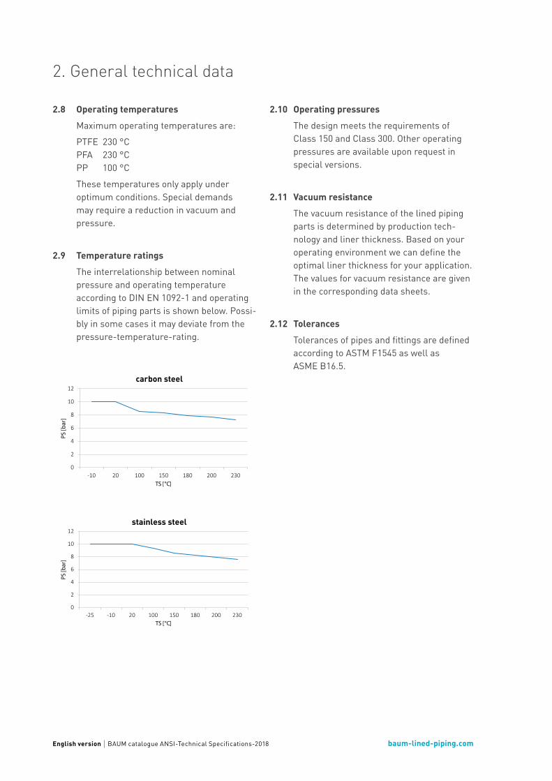
English version BAUM catalogue ANSI-Technical Specifications-2018 baum-lined-piping.com
2. General technical data
2.8 Operating temperatures
Maximum operating temperatures are :
PTFE 230 °C PFA 230 °C PP 100 °C
These temperatures only apply under optimum conditions. Special demands may require a reduction in vacuum and pressure.
2.9 Temperature ratings
The interrelationship between nominal pressure and operating temperature according to DIN EN 1092-1 and operating limits of piping parts is shown below. Possi-bly in some cases it may deviate from the pressure-temperature-rating.
2.10 Operating pressures
The design meets the requirements of Class 150 and Class 300. Other operating pressures are available upon request in special versions.
2.11 Vacuum resistance
The vacuum resistance of the lined piping parts is determined by production tech-nology and liner thickness. Based on your operating environment we can define the optimal liner thickness for your application. The values for vacuum resistance are given in the corresponding data sheets.
2.12 Tolerances
Tolerances of pipes and fittings are defined according to ASTM F1545 as well as ASME B16.5.
0
2
4
6
8
10
12
-10 20 100 150 180 200 230
PS [b
ar]
TS [°C]
Rohrklasse 10GN01B1carbon steel
0
2
4
6
8
10
12
-25 -10 20 100 150 180 200 230
PS [b
ar]
TS [°C]
Rohrklasse 10GN51B1stainless steel

English version BAUM catalogue ANSI-Technical Specifications-2018 baum-lined-piping.com
3. Quality management3.1 Welding
Our welding processes are subject to the following criteria:
1. We are a certified manufacturer in ac-cordance with AD 2000-Merkblatt HP O, HP 100 R / DIN EN ISO 3834-2 / DIN EN 13480.
2. Our processes conform to AD 2000- Merkblatt HP 2 / 1 / DIN EN 13480.
3. Our operations are supervised by a certified welding expert.
4. We only employ welders with a AD 2000- Merkblatt HP 3 / DIN EN 13480 certifi-cate.
3.2 Material quality certificates BAUMCert®
All steel pipes, flanges, stub ends and welded steel fittings are certified according to DIN EN 10204 - 3.1.
3.3 Raw material checks
Lining materials are only procured with material quality certificates WAZ 2.2 from manufacturers certified according to ISO 9001.
3.4 Visual and dimensional checks
In addition, our own laboratory continually checks and records the physical data of semifinished products from the produc-tion line. The dimensions of all pipes and fittings are checked visually.
3.5 Spark tests
All non-conductive lined pipes and fittings subjected a 25kV or 30kV spark test to make sure the lining is not porous.
3.6 Hydrostatic tests
The hydrostatic test is carried out at the 1.43-times of the nominal pressure.
3.7 Marking
In accordance with ASTM F1545, every pipe and fitting is marked on the circumference of the flange as follows:
• Manufacturer's name
• Production lot
• Lining material
• Date of production
• CE marking (if applicable)
Additional markings – for example mate-rial no. etc. – are available upon customer request.

English version BAUM catalogue ANSI-Technical Specifications-2018 baum-lined-piping.com
3. Quality management
3.8 Certificates

English version BAUM catalogue ANSI-Technical Specifications-2018 baum-lined-piping.com
4.1 Protective covers
Protective covers must only be removed immediately before fitting.
4.2 Gaskets
Flared surfaces of identical materials (PTFE/PFA) do not require gaskets. Gaskets are only needed for connections frequently undone or for connections to other materi-als such as metal, glass, enamel, etc.
4.3 Tightening torques (for pressure rating Class 150)
When using smooth-running and greased bolts and nuts we recommend the tighten-ing torques in the table below:
The torque wrench should be used in a cross manner. Tightening torques for other pressure rates available upon request. Details for assembly and operating instruc-tions can be found in our data sheet FB 8.3.5.
4.4 Welding operations
Lined pipes and fittins may not be welded, as the high temperature will destroy the synthetic material.
4.5 Vent holes
Vent holes should at all times be kept open. Not clog them with paint or insulating ma-terial.
4.6 Permeation and diffusion
The term "permeation" defines the particle transport of operating medium in a piping through the lining. Permeation is caused by two physical indidents. First, the diffusion of the operating medium through the spaces between the molecules of the plastic. Sec-ond, the solubility of the operating medium in the polymer (absorption). Diffusion can be decreased by the choice of suitable types of PTFE, by increasing the liner thickness and by using higher levels of crytallinity. However, this increases the risk of cracks caused by strain. To ensure optimal product safety all aspects have to taken into consid-eration. Absorption defines the difussion of operating medium into the liner.
Cyclical stress due to temperature or pres-sure leads to elogation mechanisms which cause aggregations of operating medium and even blisters. Isolation of those piping parts can avoid or reduce those effects considerably.
4. Fitting instructions
NPS Bolts Tightening torques
(Nm)
1/2" 4 x 1/2" 6
3/4" 4 x 1/2" 10
1" 4 x 1/2" 14
1 1/2" 4 x 1/2" 28
2" 4 x 5/8" 53
2 1/2" 4 x 5/8" 66
3" 4 x 5/8" 94
4" 8 x 5/8" 67
5" 8 x 3/4" 101
6" 8 x 3/4" 128
8" 8 x 3/4" 178
10" 12 x 7/8" 175
12" 12 x 7/8" 228
14" 12 x 1" 285
16" 16 x 1" 265
18" 16 x 1 1/8" 389
20" 20 x 1 1/8" 344

English version BAUM catalogue ANSI-Technical Specifications-2018 baum-lined-piping.com
6. Notes on product development
5.1 PTFE
PTFE has a universal chemical resistance against almost all chemicals and solvents within its continuous operating tempera-ture – with the exception of molten alkalis, elementary flourine and certain halogenes.
5.2 PFA
Properties of PFA are comparable to PTFE (see 5.1).
5.3 PP
Please refer to the information specified by the manufacturer.
We reserve the right to vary between the lining materials PTFE and PFA for manufacturing reasons.
This product catalog is based on the experience we have gained up to now, it is intended to provide the user with advice.
All information is to the best of our knowledge and believed to be correct and given without responsibility. Illustrations of products are shown exemplary and do not necessarily represent the actual shape.
Technical changes resulting from the further development of our products may occur without giving prior notice.
Edition 2018
5. Chemical resistance