CONTACTLESS MEASURING METHOD OF BLADE ... Proch´azka P. et al.: Contactless Measuring Method of...
14
Engineering MECHANICS, Vol. 17, 2010, No. 3/4, p. 173–186 173 CONTACTLESS MEASURING METHOD OF BLADE VIBRATION DURING TURBINE SPEED-UP Pavel Proch´azka, Frantiˇ sek Vanˇ ek, Jan Cibulka, V´ ıtˇ ezslav Bula* A novel method of contactless measurement of turbine blade vibration during increas- ing (decreasing) operational speed is presented. The method is based on evaluation of time differences of blade passages along contactless sensors placed on the stator, and substitutional data correction using a numerical model. The method has been verified both numerically and experimentally. For the experimental research on the bladed model wheel of the Institute of Thermomechanics and subsequent applications under operating conditions, two new types of sensors functioning on magnetoresistive and induction principle have been developed. Keywords : rotor blade vibration, contactless measurement, tip-timing 1. Introduction Measurement system VDS-UT (Vibrodiagnostic System UT) has been recently developed in the Institute of Thermomechanics of the Academy of Sciences of the Czech Republic for contacless measurement of turbine blade vibration [1], [4], [5], [6]. This system has been focused on the analysis of vibration of steam turbine blades operating at a constant rotor speed. The aim of presented research work was to design and verify on an experimental model a new method for contactless measurements of transient phenomena, when natural frequencies of blades with large vibration amplitudes may be significantly excited (e.g. by passing critical speed during turbine speed-up). Measurements at irregular rotation of the machine required changes in both sensing and evaluating units of the vibrodiagnostic system. New algorithms based on a comparison of separate blade deflections with an original state (etalon) enable to detect changes in vibration characteristics of blades and thus their possible damage due to an inappropriate operational regime or material defects. 2. The numerical model Information on regimes of turbine speed-up has been obtained from several power plants, and also measurements by means of the storage oscilloscope Yokogawa DL750 were per- formed, to establish the maximal value of a turbine speed acceleration. The measurements evaluated and information received indicate that the turbines accelerate to the operational speed with practically constant angular acceleration, ranging up to 10 rad s −2 . The typical course of turbine speed-up in time can be seen in Fig. 1. Two constant horizontal sec- tions represent warming-up time delays. Turbine rotational speed increases linearly under electronic control. A uniformly accelerated rotational motion has been presumed for the numerical model. * Ing. P. Proch´azka, CSc., Ing. F. Vanˇ ek, CSc., J. Cibulka, Ing. V. Bula, Institute of Thermomechanics AS CR, Dolejˇ skova 5, 182 00 Praha 8, Czech Republic
Transcript of CONTACTLESS MEASURING METHOD OF BLADE ... Proch´azka P. et al.: Contactless Measuring Method of...

Engineering MECHANICS, Vol. 17, 2010, No. 3/4, p. 173–186 173
CONTACTLESS MEASURING METHOD OF BLADEVIBRATION DURING TURBINE SPEED-UP
Pavel Prochazka, Frantisek Vanek, Jan Cibulka, Vıtezslav Bula*
A novel method of contactless measurement of turbine blade vibration during increas-ing (decreasing) operational speed is presented. The method is based on evaluationof time differences of blade passages along contactless sensors placed on the stator,and substitutional data correction using a numerical model. The method has beenverified both numerically and experimentally. For the experimental research on thebladed model wheel of the Institute of Thermomechanics and subsequent applicationsunder operating conditions, two new types of sensors functioning on magnetoresistiveand induction principle have been developed.
Keywords : rotor blade vibration, contactless measurement, tip-timing
1. Introduction
Measurement system VDS-UT (Vibrodiagnostic System UT) has been recently developedin the Institute of Thermomechanics of the Academy of Sciences of the Czech Republic forcontacless measurement of turbine blade vibration [1], [4], [5], [6]. This system has beenfocused on the analysis of vibration of steam turbine blades operating at a constant rotorspeed. The aim of presented research work was to design and verify on an experimentalmodel a new method for contactless measurements of transient phenomena, when naturalfrequencies of blades with large vibration amplitudes may be significantly excited (e.g. bypassing critical speed during turbine speed-up). Measurements at irregular rotation of themachine required changes in both sensing and evaluating units of the vibrodiagnostic system.New algorithms based on a comparison of separate blade deflections with an original state(etalon) enable to detect changes in vibration characteristics of blades and thus their possibledamage due to an inappropriate operational regime or material defects.
2. The numerical model
Information on regimes of turbine speed-up has been obtained from several power plants,and also measurements by means of the storage oscilloscope Yokogawa DL750 were per-formed, to establish the maximal value of a turbine speed acceleration. The measurementsevaluated and information received indicate that the turbines accelerate to the operationalspeed with practically constant angular acceleration, ranging up to 10 rad s−2. The typicalcourse of turbine speed-up in time can be seen in Fig. 1. Two constant horizontal sec-tions represent warming-up time delays. Turbine rotational speed increases linearly underelectronic control. A uniformly accelerated rotational motion has been presumed for thenumerical model.
* Ing. P. Prochazka, CSc., Ing. F.Vanek, CSc., J. Cibulka, Ing. V.Bula, Institute of Thermomechanics ASCR, Dolejskova 5, 182 00 Praha 8, Czech Republic

174 Prochazka P. et al.: Contactless Measuring Method of Blade Vibration During Turbine Speed-Up
Fig.1: A sample record of turbine speed-up acceleration
Fig.2: Block diagram of the contactless vibrodiagnostic system
A block diagram of the 8-channel vibrodiagnostic system can be seen from in Fig. 2. Thecontactless sensors S1 to S8 placed on the stator generate impulse signals by passages ofeach turbine blade tip. The sensor S0 detects the passages of a magnetic reference markattached to the shaft.
Impulse output signals of the sensors S0 to S8 are digitized and connected to the centralmeasuring unit DIO. This unit includes a precise counter and, as the result, a numericalvalue of time is assigned to each generated pulse. The time data complemented by a sensoraddress and auxiliary operational analogue readouts are sent to a local or distant (via modemor net) computer (PC). Time differences of each blade passage are calculated and transferredto circumferential deflections and subsequently to blade bending deflections. Using the algo-rithm of DFT, the amplitudes and frequencies of vibration of all blades can be ascertained.This method is often referred as tip-timing.
A numerical model has been developed to simulate contactless sensing and evaluationprocess of rotor blade vibration, when increasing or decreasing the turbine speed. Thenumerical model was implemented in the program environment TestPoint 6.1. Consideringuniform approaching the operational speed 3000 rpm of real turbines, a uniformly accele-

Engineering MECHANICS 175
rated rotational motion of the rotor with a constant angular acceleration is assumed in themathematical model. The basic equation of the motion can be expressed as
σ = ω0 t+α t2
2, (1)
where σ [rad] is the angular distance, ω0 [rad s−1] is the angular velocity for t = 0, t [s]is time and α [rad s−2] is the angular acceleration. Assuming contacless sensors equallyspaced around the perimeter of the stator, we get for the angular distance of the j-th sensor,j = 1, 2, . . . , ns
σ =2πns
j . (2)
Solving equation (1), we obtain the real root for the time of the blade passage around thej-th sensor
ts =−ω0 +
√ω2
0 +4π αns
j
α. (3)
The numerical model is based on this solution. The interactive control panel of thenumerical model can be seen in Fig. 3. The program allows entering parameters of bladevibration (frequency, amplitude and phase shift of two main components of bending vibrationin the circumferential direction), an instantaneous state of the turbine (initial speed, angularacceleration) and the vibrodiagnostic system (number of contactless sensors on the statorand their angular distance).
The model can take into account failure of a sensor as well. The example in Fig. 3 simu-lates the state of the vibrodiagnostic system with 7 functioning sensors and one sensor out
Fig.3: The control panel and the display of the numerical model

176 Prochazka P. et al.: Contactless Measuring Method of Blade Vibration During Turbine Speed-Up
of order. A uniform distribution of sensors along the perimeter of the stator is assumed.The corresponding sequence of samples of time differences, which is the input for the dis-crete Fourier transform (DFT), is compiled from data generated by the modelled passageof blades along contactless stator sensors (upper graph). The output of the model is thelinear amplitude spectrum of time differences of vibrating blades during uniformly acceler-ated rotational motion of the rotor (lower graph). The numerical values of the frequencyand the amplitude of the main spectral function component are displayed. The result of thecalculation provides further auxiliary information, e.g. range of the spectrum, initial angularvelocity ω0 and the time of the blade passage along a given sensor. Appropriate measuringmethod can be designed and optimised by this numerical model, permitting thus utilizationof this method for precise measurements during turbine speed acceleration.
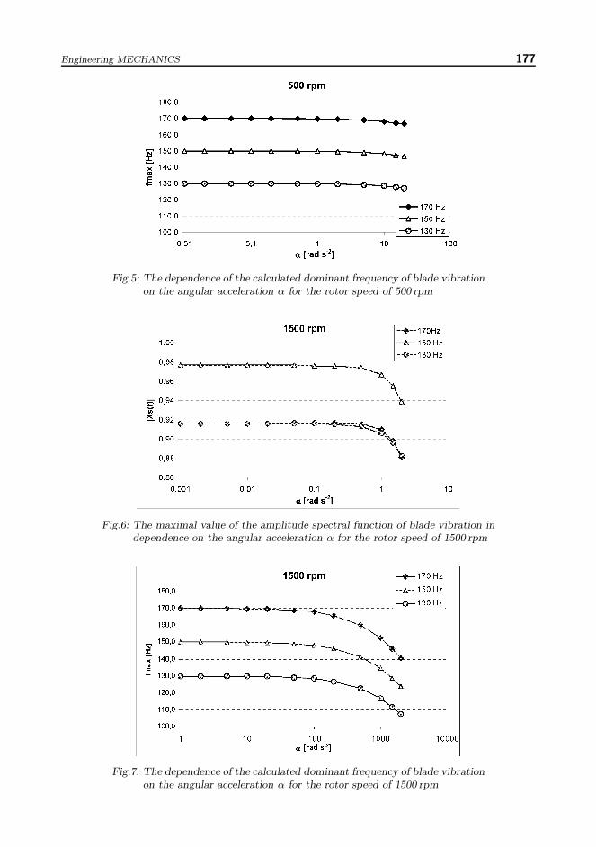
Features of contactless vibrodiagnostic systems based on the method of time differenceswere analysed for a wide range of angular acceleration (from 0.01 to 2000 rad s−2). Forthe rotational speed varying from 100 rpm to 3000 rpm, the impact of angular accelerationon the frequency and amplitude of blade vibrations was examined. For these calculations,natural frequencies of 130, 150 and 170Hz were chosen, as they correspond to the realvalues of natural frequencies of the long blades of low-pressure turbine stages, e.g. in powerstations Prunerov and Temelın. Examples of dependence obtained by the numerical modelcalculations for 500, 1500 and 3000 rpm are shown in Figs. 4 to 10. While the frequency
Fig.4: The maximal value of the amplitude spectral function of blade vibration independence on the angular acceleration α for the rotor speed of 500 rpm
Engineering MECHANICS 177
Fig.5: The dependence of the calculated dominant frequency of blade vibrationon the angular acceleration α for the rotor speed of 500 rpm
Fig.6: The maximal value of the amplitude spectral function of blade vibration independence on the angular acceleration α for the rotor speed of 1500 rpm
Fig.7: The dependence of the calculated dominant frequency of blade vibrationon the angular acceleration α for the rotor speed of 1500 rpm

178 Prochazka P. et al.: Contactless Measuring Method of Blade Vibration During Turbine Speed-Up
Fig.8: The maximal value of the amplitude spectral function of blade vibration independence on the angular acceleration α for the rotor speed of 3000 rpm
Fig.9: The dependence of the calculated dominant frequency of blade vibrationon the angular acceleration α for the rotor speed of 3000 rpm
Fig.10: The value of angular acceleration α resulting in the decrease d|Xs(f)| = 0.001of the maximum of the amplitude spectrum in dependence on rpm

Engineering MECHANICS 179
error pertains to the values of angular acceleration α > 10 rad s−2, the amplitude error isalready discernible at α > 0.01 rad s−2. For higher values of α > 1 rad s−2, we can observea decreasing character of the amplitude spectral function verging to a chaotic character.This effect is caused by the properties of DFT.
The dependence of the angular acceleration α resulting in the decrease d|Xs(f)| = 0.001of the amplitude spectrum maximum on rpm can be seen from Fig. 10. Sensitivity to thevalue of acceleration depends on the instantaneous rotor speed. For low values of the ro-tor speed, already small values of acceleration α can cause relatively large changes of themaximum of the amplitude spectral function of blade vibration. The amplitude error dueto these changes decreases with the rotor speed. Hence, the limit for a fixed amplitudedecrease (d|Xs(f)| = 0.001 for example in Fig. 10) increases with increasing rotor speed.Similar curves can be observed for the frequencies 130, 150 and 170Hz. The dashed lineshows an average curve.
Fig.11: Emergence of the side bands by 200 rpm and α = 1 [rad s−2]
Based on the knowledge obtained from the numerical modelling, a substitutional methodfor correcting measurement errors caused by acceleration of the machine has been proposed.At first, initial rotor speed is ascertained by a precise time measurement of passages ofmagnetic marks placed on the rotor. Similar method is used to determine acceleration ofthe rotor. Subsequently, the value of acceleration is put to zero and primary approximatecharacteristics of blade vibration are calculated. Then, assuming a constant average valueof real acceleration, the obtained values are entered to the numerical model, which yieldscorrect data. This method enables measuring even at high angular acceleration values, whenthe results would be greatly distorted by large amplitude and frequency errors.
Increasing the angular acceleration at high rotational speed or decreasing rotational speedat higher values of a constant angular acceleration, we can observe phenomena of formation
180 Prochazka P. et al.: Contactless Measuring Method of Blade Vibration During Turbine Speed-Up
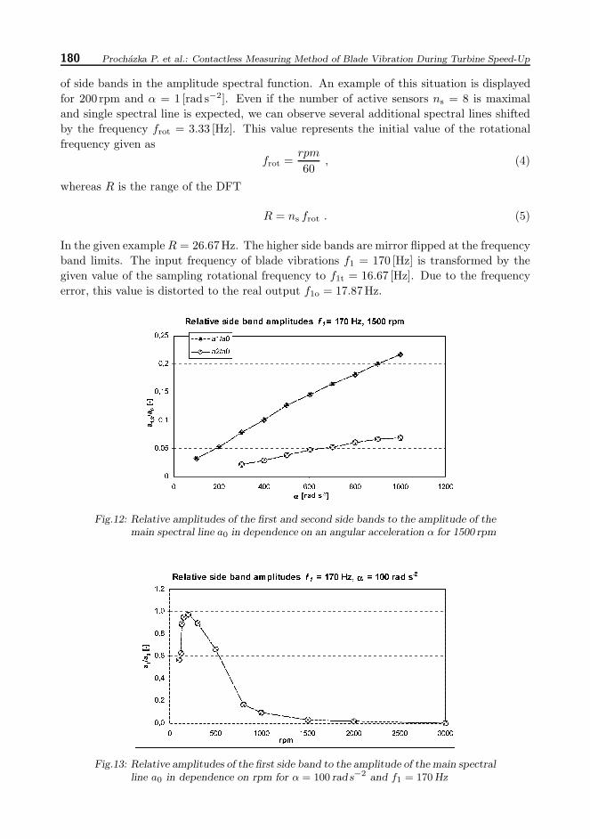
of side bands in the amplitude spectral function. An example of this situation is displayedfor 200 rpm and α = 1 [rad s−2]. Even if the number of active sensors ns = 8 is maximaland single spectral line is expected, we can observe several additional spectral lines shiftedby the frequency frot = 3.33 [Hz]. This value represents the initial value of the rotationalfrequency given as
frot =rpm
60, (4)
whereas R is the range of the DFT
R = ns frot . (5)
In the given example R = 26.67Hz. The higher side bands are mirror flipped at the frequencyband limits. The input frequency of blade vibrations f1 = 170 [Hz] is transformed by thegiven value of the sampling rotational frequency to f1t = 16.67 [Hz]. Due to the frequencyerror, this value is distorted to the real output f1o = 17.87Hz.
Fig.12: Relative amplitudes of the first and second side bands to the amplitude of themain spectral line a0 in dependence on an angular acceleration α for 1500 rpm
Fig.13: Relative amplitudes of the first side band to the amplitude of the main spectralline a0 in dependence on rpm for α = 100 rad s−2 and f1 = 170 Hz

Engineering MECHANICS 181
Occurrence of side bands has been studied for a wide range of rotational speed from 100to 3000 rpm. The dependence of the relative amplitude of the first and second side bandsa1/a0 and a2/a0, respectively, for the speed 1500 rpm and the vibration frequency 170Hzcan be seen in the example in Fig. 12.
Assuming a fixed angular acceleration α we can study the dependence of the ratio of theside band amplitude and of the appropriate maximum of the spectral amplitude function.An example of the dependence of the relative side band amplitude on the rotor speed isshown in Fig. 13. The curve is characterized by a maximum around 200 rpm and a fallingcourse with increasing speed.
3. Experimental verification of the method
For the experimental verification of the method, two new types of blade passage sensorshave been developed and both static and dynamic characteristics of these sensors have beenverified. Special emphasis was placed on the resilience and endurance of these sensors, sothat they could be utilized under real operational conditions. The sensors were used in thecontacless vibrodiagnostic system VDS-UT at the power station Temelın. For protectionof intellectual property associated with the development of new types of sensors, patentapplications [2], [3] have been submitted for registration.
Both inductive and magnetoresistive sensors developed for sensing a position of rotatingmachine parts operate as contactless sensors located on the machine stator. The magne-toresistive sensors provide increased linearity and accuracy, and feature optimum directionof magnetization and the symmetry of the output signal. Current supplied sensors canmeasure their own internal temperature as well. Magnetoresistive sensors can be used formeasurements by the circumferential speeds up to 700m/s and ambient temperatures upto 200 ◦C. The construction of the sensor prevents water erosion. The photograph of themagnetoresistive sensor is shown in Fig. 14.
Fig.14: A contactless magnetoresistive sensor
The function of the modified arrangement of the vibrodiagnostic system for measuringduring wheel speed-up and slow-down has been verified. Experiments were carried out onthe experimental model of the bladed wheel fitted with 47 prismatic blades in the dynamiclaboratory of the Institute of Thermomechanics. Necessary adjustments of regulation circuitsof the wheel had been performed, which allowed uniform increase of the wheel speed in therange from 0 to 720 rpm with an angular acceleration from 0.01 to 1 [rad s−2]. To calibrate theproposed measuring method, existing strain gauge system of the model wheel was utilized.The arrangement of the model wheel can be seen in Fig. 15.

182 Prochazka P. et al.: Contactless Measuring Method of Blade Vibration During Turbine Speed-Up
Examples of measurements performed on the model wheel during its uniformly accele-rating speed from 0 rpm to 720 rpm are presented in Figs. 16 and 17 showing the recordstaken by the memory oscilloscope Yokogawa DL750. Channel 1 FZ shows the signal of thereference phase mark, channel 2 TL1 shows voltage output of a strain gauge located on theblade No. 1, channel 4 MR shows voltage output of the contacless magnetoresistive sensorMR1 and channel 6 60l shows the output of an auxiliary reference blade signal. The diskof the wheel was excited by a magnetic field of an alternating electromagnet with constantfrequency of 60Hz.
Fig.15: The experimental model of the bladed wheel in the dynamic laboratory
It can be observed from the signal envelope of the strain gauge in channel 2 TL1 thatby increasing the speed, initially the first mode shape and in the following section also thesecond mode shape are subsequently excited. While blade vibration is apparent from theamplitudes of the strain gauge signal, the corresponding information can be obtained fromthe output signal of the contactless magnetoresistive sensor using data processing methodof time or amplitude differences.
A more detailed record involving one revolution of 627 rpm can be seen in Fig. 17. Thestrain gauge resonant signal is apparently modulated by a close harmonic signal. The trace4 MR shows impulses generated by passages of single blades. From amplitude and timechanges of these impulse signals, the static and dynamic characteristics of blade vibrationcan be evaluated.
Calculating the linear amplitude spectra of the strain gauge signal and the magnetoresis-tive sensor signal by the software Viewer by Yokogawa, we can draw conclusions regardingcharacter of vibration of the examined bladed wheel. Results of FFT calculations for 420 rpmin Fig. 18 show the dominant frequency of the amplitude spectrum of the magnetoresitivesensor 61Hz, which corresponds to the frequency of the exciting signal of the electromagnet.The dominant frequency of the amplitude spectrum of the strain gauge signal is shifteddown by the frequency of rotation frot = 7Hz, which indicates excitation of a forward wave.

Engineering MECHANICS 183
Fig.16: Measurements of uniformly accelerated rotation from 0 rpm to 720 rpmon the experimental model wheel recorded by a storage oscilloscope
Fig.17: Measurement of uniformly accelerated rotation from 0 rpm to 720 rpmon the experimental model wheel recorded by the storage oscilloscopeYokogawa DL750. More detailed record of one revolution by 627 rpm
Fig.18: Linear amplitude spectra by 420 rpm (7Hz) with dominant frequenciesof LS(TL1) : 54 Hz, 68Hz, 74Hz and LS(MR1) : 61 Hz

184 Prochazka P. et al.: Contactless Measuring Method of Blade Vibration During Turbine Speed-Up
Fig.19: Linear amplitude spectra by 590 rpm (9.8 Hz) with dominant frequenciesof LS(TL1) : 51Hz, 61 Hz, 79 Hz and LS(MR1) : 61 Hz
In the second resonant range with higher rotational speed, the reverse frequency shift,leading to the higher value of the strain gauge dominant frequency compared to the excitationfrequency, proves excitation of a backward wave (Fig. 19).
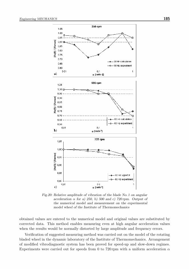
As results from the numerical modeling, negligible frequency errors occurred in the in-terval α = 〈0.01, 1〉 of the values of the angular acceleration adjustable on the experimentalmodel. Consequently, only amplitude errors are measurable. Measured values were com-pared with the values calculated by means of the numerical model for speed ranging from250 to 720 rpm. Examples of measured a calculated dependence of the relative amplitude ofvibration on an angular acceleration α for 250, 500 and 720 rpm can be seen in Figs. 20a),20b) and 20c), respectively. The axial deflections of prismatic blades of the wheel model wereconverted into the radial direction by the angle edges of the blades (see Fig. 15). The am-plitudes are related to the maximum values of the amplitude spectral function. From thesediagrams, a good agreement of the experiment with the numerical modeling is apparent.
4. Conclusion
Possibilities and restrictions of contactless measurements of vibration characteristics ofturbine blades during increasing or decreasing operational turbine speed have been deter-mined.
Modelling numerically contactless vibrodiagnostic process and assuming uniformly acce-lerated rotational movement, characteristics of a contactless measurement system based onthe method of time differences were analysed for a wide range of values of angular accelera-tion α from 0.001 to 2000 rad s−2. The influence of variation of the angular acceleration onthe resulting values of frequency and amplitude of blade vibration was investigated for thespeed range of 100 rpm to 3000 rpm.
Based on the numerical modelling, a substitution method for correcting errors causedby a non-zero rotor angular acceleration has been suggested. First, the initial rotationalspeed is ascertained by a precise time measurement of passages of magnetic marks placedon the rotor. Then, the same procedure is used to determine an instantaneous accelerationof the rotor. Subsequently, characteristics of blade vibrations are calculated for the rotationwithout acceleration. Then, assuming a constant average value of real acceleration, the
Engineering MECHANICS 185
Fig.20: Relative amplitude of vibration of the blade No. 1 on angularacceleration α for a) 250, b) 500 and c) 720 rpm. Output ofthe numerical model and measurement on the experimentalmodel wheel of the Institute of Thermomechanics
obtained values are entered to the numerical model and original values are substituted bycorrected data. This method enables measuring even at high angular acceleration valueswhen the results would be normally distorted by large amplitude and frequency errors.
Verification of suggested measuring method was carried out on the model of the rotatingbladed wheel in the dynamic laboratory of the Institute of Thermomechanics. Arrangementof modified vibrodiagnostic system has been proved for speed-up and slow-down regimes.Experiments were carried out for speeds from 0 to 720 rpm with a uniform acceleration α

186 Prochazka P. et al.: Contactless Measuring Method of Blade Vibration During Turbine Speed-Up
ranging from 0.01 to 1 [rad s−2]. For the experiments, two new types of blade passagesensors have been developed and their static and dynamic characteristics have been verified.Magnetoresistive sensors feature extremely rapid dynamic response, which allows precisemeasurements even by peripheral speeds up to 700 [m/s]. High resilience and endurance ofthese sensors enables their usage in operational conditions at real power plants. The sensorswere applied in the contacless vibrodiagnostic system VDS-UT installed at the power stationTemelın.
Acknowledgement
The research was supported and carried out within the pilot project of the research planNo. AV0Z20760514 of the Institute of Thermomechanics.
References[1] Prochazka P., Vanek F., Pesek L., Cibulka J., Vanek P.: An improvement of the vibrodiagnostic
system for research of rotating machine parts vibration (in Czech), Dynamika stroju 2009,
Praha : Ustav termomechaniky AV CR, v.v.i., 2009, p. 97–106[2] Prochazka P., Vanek F., Pesek L., Cibulka J., Vanek P.: Inductive sensor for sensing position
of rotating machine parts (in Czech), Utility model application: PUV 2009-21775.[3] Prochazka P., Vanek F., Pesek L., Cibulka J., Vanek P.: Magnetoresistive sensor for sensing
position of rotating machine parts (in Czech), Utility model application: PUV 2009-21776[4] Prochazka P., Vanek F., Pesek L., Cibulka J., Vanek P. : A technology of contactless vibro-
diagnostics of blades of steam turbines low-pressure parts (in Czech), Knowledge of researchand development RIV/61388998 /07: 00309252, 2008
[5] Vanek F., Pesek L., Prochazka P., Vanek P., Cibulka J.: Vibrodiagnostic systems for dynamicparameter measurement of rotating parts in power industry (in Czech), Proc. of the conferenceParnı turbıny a jine turbostroje 2007, Plzen : A.S.I-Turbostroje Plzen, Skoda Power a.s.,Zapadoceska univerzita v Plzni, FST, KKE, 2007 p. 23/1–23/8
[6] Danek O., Vanek F., Prochazka P., Kozanek J., Pesek L.: Diagnostic Magneto-Kinetic Equip-ment MK3, Book of Abstracts – Identification and Updating Methods of Mechanical Structures
– EUROMECH 437, Praha : Ustav termomechaniky AV CR, 2002, p. 12, ISBN 80-85918-73-0
Received in editor’s office : March 23, 2010Approved for publishing : June 4, 2010
Note : This paper is an extended version of the contribution presented at the nationalcolloquium with international participation Dynamics of Machines 2010 in Prague.